US7158046B2 - System and method for radio frequency tag group select - Google Patents
System and method for radio frequency tag group select Download PDFInfo
- Publication number
- US7158046B2 US7158046B2 US10/979,866 US97986604A US7158046B2 US 7158046 B2 US7158046 B2 US 7158046B2 US 97986604 A US97986604 A US 97986604A US 7158046 B2 US7158046 B2 US 7158046B2
- Authority
- US
- United States
- Prior art keywords
- slaves
- state
- command
- condition
- slave
- Prior art date
- Legal status (The legal status is an assumption and is not a legal conclusion. Google has not performed a legal analysis and makes no representation as to the accuracy of the status listed.)
- Expired - Fee Related
Links
Images


Classifications
-
- G—PHYSICS
- G06—COMPUTING; CALCULATING OR COUNTING
- G06K—GRAPHICAL DATA READING; PRESENTATION OF DATA; RECORD CARRIERS; HANDLING RECORD CARRIERS
- G06K7/00—Methods or arrangements for sensing record carriers, e.g. for reading patterns
- G06K7/10—Methods or arrangements for sensing record carriers, e.g. for reading patterns by electromagnetic radiation, e.g. optical sensing; by corpuscular radiation
- G06K7/10009—Methods or arrangements for sensing record carriers, e.g. for reading patterns by electromagnetic radiation, e.g. optical sensing; by corpuscular radiation sensing by radiation using wavelengths larger than 0.1 mm, e.g. radio-waves or microwaves
- G06K7/10019—Methods or arrangements for sensing record carriers, e.g. for reading patterns by electromagnetic radiation, e.g. optical sensing; by corpuscular radiation sensing by radiation using wavelengths larger than 0.1 mm, e.g. radio-waves or microwaves resolving collision on the communication channels between simultaneously or concurrently interrogated record carriers.
- G06K7/10108—Methods or arrangements for sensing record carriers, e.g. for reading patterns by electromagnetic radiation, e.g. optical sensing; by corpuscular radiation sensing by radiation using wavelengths larger than 0.1 mm, e.g. radio-waves or microwaves resolving collision on the communication channels between simultaneously or concurrently interrogated record carriers. interrogating only those RFIDs that fulfill a predetermined requirement, e.g. selecting all RFIDs having the same speed and moving in a cloud like fashion, e.g. on the same train; interrogating only RFIDs having a certain predetermined temperature, e.g. in the same fridge, another possibility being the active ignoring of a group of tags that fulfill a predetermined requirement, equivalent to the Boolean NOT operation
-
- G—PHYSICS
- G05—CONTROLLING; REGULATING
- G05B—CONTROL OR REGULATING SYSTEMS IN GENERAL; FUNCTIONAL ELEMENTS OF SUCH SYSTEMS; MONITORING OR TESTING ARRANGEMENTS FOR SUCH SYSTEMS OR ELEMENTS
- G05B19/00—Programme-control systems
- G05B19/02—Programme-control systems electric
- G05B19/04—Programme control other than numerical control, i.e. in sequence controllers or logic controllers
- G05B19/042—Programme control other than numerical control, i.e. in sequence controllers or logic controllers using digital processors
- G05B19/0421—Multiprocessor system
-
- G—PHYSICS
- G06—COMPUTING; CALCULATING OR COUNTING
- G06K—GRAPHICAL DATA READING; PRESENTATION OF DATA; RECORD CARRIERS; HANDLING RECORD CARRIERS
- G06K7/00—Methods or arrangements for sensing record carriers, e.g. for reading patterns
- G06K7/0008—General problems related to the reading of electronic memory record carriers, independent of its reading method, e.g. power transfer
-
- G—PHYSICS
- G06—COMPUTING; CALCULATING OR COUNTING
- G06K—GRAPHICAL DATA READING; PRESENTATION OF DATA; RECORD CARRIERS; HANDLING RECORD CARRIERS
- G06K7/00—Methods or arrangements for sensing record carriers, e.g. for reading patterns
- G06K7/10—Methods or arrangements for sensing record carriers, e.g. for reading patterns by electromagnetic radiation, e.g. optical sensing; by corpuscular radiation
- G06K7/10009—Methods or arrangements for sensing record carriers, e.g. for reading patterns by electromagnetic radiation, e.g. optical sensing; by corpuscular radiation sensing by radiation using wavelengths larger than 0.1 mm, e.g. radio-waves or microwaves
- G06K7/10019—Methods or arrangements for sensing record carriers, e.g. for reading patterns by electromagnetic radiation, e.g. optical sensing; by corpuscular radiation sensing by radiation using wavelengths larger than 0.1 mm, e.g. radio-waves or microwaves resolving collision on the communication channels between simultaneously or concurrently interrogated record carriers.
- G06K7/10029—Methods or arrangements for sensing record carriers, e.g. for reading patterns by electromagnetic radiation, e.g. optical sensing; by corpuscular radiation sensing by radiation using wavelengths larger than 0.1 mm, e.g. radio-waves or microwaves resolving collision on the communication channels between simultaneously or concurrently interrogated record carriers. the collision being resolved in the time domain, e.g. using binary tree search or RFID responses allocated to a random time slot
- G06K7/10039—Methods or arrangements for sensing record carriers, e.g. for reading patterns by electromagnetic radiation, e.g. optical sensing; by corpuscular radiation sensing by radiation using wavelengths larger than 0.1 mm, e.g. radio-waves or microwaves resolving collision on the communication channels between simultaneously or concurrently interrogated record carriers. the collision being resolved in the time domain, e.g. using binary tree search or RFID responses allocated to a random time slot interrogator driven, i.e. synchronous
-
- G—PHYSICS
- G07—CHECKING-DEVICES
- G07C—TIME OR ATTENDANCE REGISTERS; REGISTERING OR INDICATING THE WORKING OF MACHINES; GENERATING RANDOM NUMBERS; VOTING OR LOTTERY APPARATUS; ARRANGEMENTS, SYSTEMS OR APPARATUS FOR CHECKING NOT PROVIDED FOR ELSEWHERE
- G07C9/00—Individual registration on entry or exit
- G07C9/20—Individual registration on entry or exit involving the use of a pass
- G07C9/28—Individual registration on entry or exit involving the use of a pass the pass enabling tracking or indicating presence
-
- G—PHYSICS
- G08—SIGNALLING
- G08C—TRANSMISSION SYSTEMS FOR MEASURED VALUES, CONTROL OR SIMILAR SIGNALS
- G08C17/00—Arrangements for transmitting signals characterised by the use of a wireless electrical link
- G08C17/02—Arrangements for transmitting signals characterised by the use of a wireless electrical link using a radio link
-
- G—PHYSICS
- G05—CONTROLLING; REGULATING
- G05B—CONTROL OR REGULATING SYSTEMS IN GENERAL; FUNCTIONAL ELEMENTS OF SUCH SYSTEMS; MONITORING OR TESTING ARRANGEMENTS FOR SUCH SYSTEMS OR ELEMENTS
- G05B2219/00—Program-control systems
- G05B2219/20—Pc systems
- G05B2219/22—Pc multi processor system
- G05B2219/2231—Master slave
-
- G—PHYSICS
- G05—CONTROLLING; REGULATING
- G05B—CONTROL OR REGULATING SYSTEMS IN GENERAL; FUNCTIONAL ELEMENTS OF SUCH SYSTEMS; MONITORING OR TESTING ARRANGEMENTS FOR SUCH SYSTEMS OR ELEMENTS
- G05B2219/00—Program-control systems
- G05B2219/20—Pc systems
- G05B2219/25—Pc structure of the system
- G05B2219/25277—Tristate
-
- G—PHYSICS
- G08—SIGNALLING
- G08C—TRANSMISSION SYSTEMS FOR MEASURED VALUES, CONTROL OR SIMILAR SIGNALS
- G08C2201/00—Transmission systems of control signals via wireless link
- G08C2201/20—Binding and programming of remote control devices
Definitions
- the invention relates to communications between a master station and one or more slave stations. More specifically, the invention relates to a master station selecting subset(s) of the slave stations by broadcasting commands with conditions that the selected slaves meet.
- a master control unit is to communicate with a plurality of autonomous and independent slaves
- the number of slaves is often not known a priori. There may in fact be no slaves with which the master can communicate.
- the master may have to communicate with the slaves are (a) the need to acknowledge their presence, (b) identify and count them and/or (c) order them to perform tasks.
- This kind of computational environment falls under the broader category of broadcasting sequential processes, which is defined by Narain Gehani in Chapter 9 of the book co-edited with Andrew McGettrick, “Concurrent Programming” (Addison-Wesley, 1988), which is herein incorporated by reference in its entirety.
- Finite state-machines are a well-known modeling tool. The set theory that often accompanies the definition of finite state-machines is also well known. Both subjects are amply covered in any of many books on discrete or finite mathematics that are available today. The book by Ralph Grimaldi, “Discrete and Combinatorial Mathematics: An Applied Introduction” (Addison-Wesley, 1985), is a fine example of its kind.
- the master Because the master often does not know ahead of time the number of slaves present and because that number may be very large and possibly unwieldy, it is advantageous for the master to be able to select a subset of the slaves with which to communicate further. Such a selection must of course be done by a conditional. Those slaves that meet the condition are thus considered selected, while those that do not meet the condition are considered not selected. The selection is performed by broadcasting to all slaves the condition that must be met. This is akin to asking those among a large crowd of people whose last name is Lowell to raise their hand. Each slave is defined as having at least the capability to listen to The master's broadcasts, to receive the broadcast condition and to self-test so as to determine whether it meets the condition. See U.S.
- U.S. Pat. No. 5,673,037 in turn incorporates U.S. Pat. No. 5,550,547 by reference in its entirety, and accordingly, U.S. Pat. No. 5,550,547 is hereby incorporated herein by reference in its entirety.
- U.S. Pat. No. 5,550,547 discloses a base station with a base memory ( 220 , the second figure of 5,550,547) which stores a special command structure that is used to communicate with the RFID tags.
- the base memory includes a novel command structure for tag group selection also.
- U.S. Pat. No. 5,550,547 states that group select structures are described in the U.S. patent application Ser. No. 08/303,965 entitled “SYSTEM AND METHOD FOR RADIO FREQUENCY TAG GROUP SELECT” to C. Cesar et al. filed Sep. 9, 1994 (now U.S. Pat. No. 5,673,037), which is incorporated by reference in its entirety in U.S. Pat. No. 5,550,547.
- the fifth figure of the incorporated U.S. Pat. No. 5,550,547 shows an algorithm being executed by each of a plurality of RF tags which includes processing of an identification command which in a preferred embodiment is the group select command.
- the incorporated U.S. Pat. No. 5,673,037 allows slaves to move between two selection states according to successive comparisons. That allows some complex conditions to be effected. However not all complex conditions can be effected with such two-selection-state machine.
- the complex condition “is-red and is-not-tall or is-not-red and is-tall”, that is, the EXCLUSIVE-OR of the two simple comparisons “is-red” and “is-tall” can not be performed such that the subset of slaves that satisfy the EXCLUSIVE-OR are in the first state and those that do not satisfy the EXCLUSIVE-OR are in the second state.
- the two-selection-state machine can not perform the EXCLUSIVE-OR and the EQUIVALENCE logical operators. In the case of complex conditions involving more than two comparisons and their negation, the two-selection-state machine cannot perform an increasingly large number of logical equations. Conditions such as the EXCLUSIVE-OR must be broken up into two independent processing steps. First, slaves satisfying the first AND term are selected and all necessary processing sequence is performed over them. Second, after a general reset, slaves satisfying the second AND term are selected and the same necessary processing sequence is repeated over those. That means that the processing sequence must be broadcast twice. In the case of more complicated conditions, rebroadcasting of such sequence may happen more than twice. For example, the condition (A* ⁇ B* ⁇ C)+( ⁇ A*B* ⁇ C)+( ⁇ A* ⁇ B+C) would need three rebroadcasts.
- the only conditions that can be executed in a single round of broadcasting by a two-selection-state logic are those conditions that can be expressed by a left-nested expression, such as ((A+B+C)*D*E)+F).
- AND conditions, such as (A*B*C) are particular cases of left-nested expressions.
- EXCLUSIVE-OR type conditions such as (A*B* ⁇ C)+(A* ⁇ B*C)*( ⁇ A*B*C)
- a further object of this invention is a system and method for using arbitrarily complex logical conditions to select slave stations that satisfy those conditions transmitted by a master station through a series one or more commands.
- Another object of this invention is a system and method for using arbitrarily complex logical conditions to select RF transponders that satisfy those conditions transmitted by a base station through a series one or more commands.
- the present invention also comprises a system and method for selecting a subset of a plurality of autonomous and independent slaves, wherein each slave comprises (i) a three-state machine dedicated to selection, (ii) some other stored information, and (iii) a logic to execute externally provided commands in a command sequence that exercise the three-state machine.
- the primary purpose of the commands is to effect state transitions.
- the slave receives the command, which causes a comparison to be performed against the slave's stored information, the results of which possibly causing a state transition in the slave.
- the commands in a sequence called a command sequence, are broadcast from at least one master control unit to zero or more slaves.
- the exact number of slaves may not be known by the master.
- the master executes a method by which a sequence of discrete commands is broadcast to all slaves. The overall purpose of the method is to bring a subset of the slaves to be at the same state of their three-state machine, while all other slaves are at any one of the two other remaining states.
- a three-state machine dedicated to selection is present in every slave.
- Each slave is at one of those three states, therefore, at any one time, the slaves can be sub-divided into three subsets: those slaves that have their selection three-state machine at the first state, those at the second state, and those at the third state.
- transitions are possible between any two states of the three-state machine.
- Transitions are requested by command (sequence) broadcast from the master.
- a command specifies a desired transition, say from the second state to the first state. Only slaves that are at the second state may be affected.
- the command also specifies a condition under which the transition will occur. If the condition is met, the transition is effected; if not, the slave remains in its previous state.
- slaves can be moved from a first state to a second state and visa versa. Only slaves in the second state can be moved to a third state. The slaves in the third state ignore the remaining commands in the command sequence.
- the first and second states reverse roles after an end of one or more subsequences in the sequences of commands. Also, the second and third states can reverse roles after an end of one or more subsequences. Further, the states of the slaves can cycle their roles at the end of one or more of the subsequences.
- FIG. 1 is a block diagram of a master control unit broadcasting commands to a plurality of slaves.
- FIG. 2 is a block diagram of the components of a master control unit.
- FIG. 3 is a block diagram of the components of a slave.
- FIG. 4 shows a state diagram showing a three-state machine that allows all six possible transitions between any two different states.
- FIG. 5 shows a state diagram showing a three-state machine that allows five possible transitions between any two different states.
- FIG. 6 shows a state diagram showing a three-state machine that allows four possible transitions between any two different states, such that any state is reachable from any other state.
- FIG. 7 shows a state diagram showing a three-state machine that allows four possible transitions between any two different states, such that any state is reachable from any other state and two of the states have no transitions between them.
- FIG. 8 shows a state diagram showing a three-state machine that allows three possible transitions between any two different states, such that any state is reachable from any other state.
- FIG. 9 lists all possible three-state machines that can be used for the purposes of this invention.
- FIG. 10 is a set theoretic representation of how the plurality of slaves is subdivided into at most three sets.
- FIG. 11 describes what happens when a command to transfer slaves that satisfy some condition from one state to another is broadcast.
- FIGS. 12 , 13 , 14 , 15 , 16 and 17 exemplifies by means of Venn diagrams how a command transfers elements from one set to another.
- FIGS. 18 , 19 and 20 show sequences of commands for selecting a subset of slaves that satisfy an EXCLUSIVE-OR condition and such that those slaves end up in a first, second and third set, respectively.
- FIG. 21 describes a method that computes a product (AND) condition.
- FIG. 22 describes a method that computes a negated product (NAND) condition.
- FIG. 23 describes a method that computes a sum (OR) condition.
- FIG. 24 describes a method that computes a negated sum (NOR) condition.
- FIG. 25 describes a method that computes a condition written in sum-of-products form whereby the product terms are built in a second state and the sum is accumulated in a third state.
- FIGS. 26 and 27 exemplify the use of the method described in FIG. 25 .
- FIG. 28 describes a method that computes a condition written in sum-of-products form whereby the product terms are built alternatively in a first and second states and the sum is accumulated in a third state.
- FIGS. 29 and 30 exemplify the use of the method described in FIG. 28 .
- FIG. 31 describes a method that computes a condition written in sum-of-products form whereby the product terms are built alternatively in a second and third states and the sum is accumulated in that second and third state, respectively.
- FIGS. 32 and 33 exemplify the use of the method described in FIG. 31 .
- FIG. 34 describes a method that computes a condition written in sum-of-products form whereby the product terms are built alternatively in a first, second and third states and the sum is accumulated in that first, second and third state, respectively.
- FIGS. 35 and 36 exemplify the use of the method described in FIG. 31 .
- FIG. 37 describes a method that computes a single left-nested expression using only two states.
- FIG. 38 describes a method that computes the negation of a single left-nested expression using only two states.
- FIG. 39 exemplifies the use of the method described in FIG. 37 .
- FIG. 40 exemplifies the use of the method described in FIG. 38 .
- FIG. 41 describes a method that computes a condition written in sum-of-left-nested-expressions form whereby the left-nested expressions are built in a second state and the sum is accumulated in a third state.
- FIG. 42 describes a method that computes a condition written in sum-of-left-nested-expressions form whereby the left-nested expressions are built alternatively in a first and second states and the sum is accumulated in a third state.
- FIG. 43 describes a method that computes a condition written in sum-of-left-nested-expressions form whereby the left-nested expressions are built alternatively in a second and third states and the sum is accumulated in that second and third states, respectively.
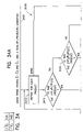
- FIG. 44 describes a method that computes a condition written in sum-of-left-nested-expressions form whereby the left-nested expressions are built in a first, second and third states and the sum is accumulated in that first, second and third states, respectively.
- FIG. 1 shows least one master control unit 101 communicating with a plurality of autonomous and independent slaves 102 .
- the communication medium 103 can be in terms of either direct electric contact means or electromagnetic radiation means, e.g., radio frequency (RF) embodiments. However, it also encompasses light, sound and other frequencies utilized for signalling purposes.
- Master unit 101 is capable of broadcasting commands at the plurality of slaves 102 via communication medium 103 .
- Each slave is capable of receiving the broadcast commands which are processed by logic 150 .
- logic 150 For example, U.S. Pat. No. 4,656,463 to Anders et al.
- FIG. 1 shows an RF tag systems where for our purposes the active transceiver (AT) would be the master control unit 101 , the passive transceivers (PT) would be the independent slaves 102 , and the communication medium 103 would be RF over free space.
- AT active transceiver
- PT passive transceivers
- U.S. Pat. No. 5,371,852 to Attanasio et al. shows a cluster of computers where for our purposes the gateway would be the master unit 101 , the nodes in the cluster would be the slaves 102 , and the communication medium 103 would be the interconnect.
- FIG. 2 shows that a master unit 200 comprises (a) means 201 for broadcasting commands from a command set 250 to a plurality of slaves, and (b) processing means 202 for determining the correct sequence of commands to be broadcast.
- processing means 202 are proximate to broadcast means 201 .
- Other embodiments are possible where processing means 202 and broadcast means 201 are remote from each other.
- FIG. 3 shows that a slave 300 comprises (a) a receiver 301 for receiving commands from a master, (b) a three-state machine 304 , (c) a memory with stored information 303 (d) processor or logic 302 for executing any received command, performing any condition testing over the stored information 303 as specified by the command, and effecting a state transition on three-state machine 304 conditional to the result of the condition testing.
- Receiving means 301 and broadcasting means 201 must be necessity be compatible.
- the receiving means 301 are well known. For example in RF tagging, radio frequency receivers/transmitters are used. In the networking arts standard connections to networks and/or information buses are used.
- Stored information 303 is typically embodied in the form of registers and/or memory.
- the three-state machine 304 comprises a select state, a first unselect state, and a second unselect state state. All three of these states can be used in the selection and unselection of sets of slaves.
- the logic 302 is further described below.
- the significant difference between a two and a three-selection-state machine is that, using any sequence of commands, the former can only isolate or select slaves that satisfy a condition expressed by a left-nested expression.
- the former can only isolate or select slaves that satisfy a condition expressed by a left-nested expression.
- a three-selection-state machine can select slaves that satisfy a condition expressed by a sum-of-left-nested-expression. Further, a three-selection-state machine is also sufficient to select a set of slaves that satisfy any arbitrary condition, even though those conditions are expressed by a sum-of-left-nested-expression. Therefore adding a fourth, fifth, etc. state does not add any new capability to the selection logic. In addition, since any condition can be expressed by a sum-of-left-nested expression, a three-selection-state machine can select a set of slave satisfying any possible condition. This capability is undisclosed and unrecognized in the prior art.
- the invention enables this capability because a separate condition (or set of conditions), each corresponding to a set of slaves, can be isolated in any one of the three states at any given time. Therefore, operations on two sets of conditions, in two of the respective states, can be performed without affecting or being affected by the conditions held in the third state.
- receiving means 301 processing means 302 , stored information 303 , and three-state machine 304 are proximate.
- processing means 302 processing means 302 , stored information 303 , and three-state machine 304 are proximate.
- the components 301 , 302 , 303 and 304 are remote from each other, in part or completely.
- the three states are dedicated to the process of determining whether a slave satisfies an arbitrarily complex condition. During the process of determining whether the slave satisfies the condition, the slave may be in any of the three states as dictated by the process. If the slave does not satisfy the condition, the process assures that the slave will end up at a state that enables the slave to communicate further with the master.
- Three-state machine 304 is part of every slave.
- a preferred three-state machine is shown in FIG. 4 .
- Three-state machine 400 includes the three states 401 , 402 and 403 , and all six possible state-to-state transitions 412 , 413 , 421 , 423 , 431 and 432 , where the transitions are between two different states.
- the three states 401 , 402 and 403 are named S 1 , S 2 and S 3 , respectively.
- a transition from a state to itself is not helpful for the methodology described herein.
- three-state machine 500 has only five of the six state-to-state transitions present in three-state machine 400 .
- Three-state machine 500 represents a class of six possible three-state machines where one of the six possible state-to-state transitions is inoperative. In the particular case of FIG. 5 , transition 413 is inoperative.
- three-state machine 600 has only four of the six state-to-state transitions of three-state machine 400 .
- the four operative transitions are such that any state can be reached from another state by means of one or two transitions. Moreover there is at least one possible transition between any two states.
- Three-state machine 600 represents a class of six possible three-state machines were two of the six possible state-to-state transitions are inoperative, while still providing access to any state from any other state. In the particular case of FIG. 6 , transitions 413 and 432 are inoperative.
- three-state machine 700 has only four of the six state-to-state transitions of three-state machine 400 .
- the four operative transitions are such that any state can be reached from another state by means of one or two transitions. Moreover there are two states between which there is no possible transition.
- Three-state machine 700 represents a class of three possible three-state machines where one of the pairs of transitions between two states is inoperative. In the particular case of FIG. 7 , the pair of transitions 413 and 431 between states 401 and 403 is inoperative.
- three-state machine 800 has only three of the six state-to-state transitions of three-state machine 400 .
- the three operative transitions are such that any state can be reached from another state by means of one or two transitions. Therefore each pair of states is connected by one and only one transition, in such a way that all transitions move either clockwise or anticlockwise.
- Three-state machine 800 represents a class of two possible three-state machines that have only three of the six state-to-state transitions.
- the three operative transitions 412 , 423 and 431 define an anticlockwise cycle.
- the six state-to-state transitions 412 , 421 , 423 , 432 , 431 and 413 are named T 12 , T 21 , T 23 , T 32 , T 31 and T 13 , respectively.
- Each row defines one possible three-state machine. For each state-to-state transition, the existence or not of that transition is indicated.
- the three-state machine defined by row 900 is a preferred embodiment that corresponds to three-state machine 400 of FIG. 4 .
- the three-state machines defined by rows 901 , 902 , 903 , 904 , 905 , and 906 belong to the class of three-state machine 500 of FIG. 5 .
- the three-state machines defined by rows 907 , 908 , 909 , 910 , 911 , and 912 belong to the class of three-state machine 600 of FIG. 6 .
- the three-state machines defined by rows 913 , 914 , and 915 belong to the class of three-state machine 700 of FIG. 7 .
- the three-state machines defined by rows 916 and 917 belong to the class of three-state machine 800 of FIG. 8 .
- each slave is at one and only one of the three states 401 , 402 , or 403 . Accordingly, there are three sets of slaves; those are state 401 , those are state 402 , and those at state 403 . State transitions are equivalent to movement between those three sets.
- This view of operating over sets is illustrated in FIG. 10 .
- Set 1001 named E 1
- Set 1002 named E 2
- Set 1003 contains as elements all slaves 1030 that are at state 403 .
- Command 1012 moves elements from set 1001 to set 1002 .
- Command 1021 moves elements from set 1002 to set 1001 .
- Command 1023 moves elements from set 1002 to set 1003 .
- Command 1032 moves elements from set 1003 to set 1002 .
- Command 1031 moves elements from set 1003 to set 1001 .
- Command 1013 moves elements from set 1001 to set 1003 .
- Command 1110 comprises three parameters. First, the “from” state 1101 ; second, the “to” state 1102 ; and third, the primitive condition 1112 which must be satisfied for the transition to happen. Those three parameters are named Si, Sj, and s, respectively in the figure. Si, the “from” state 1101 , and Sj, the “to” state 1102 , can be any of the three states 401 , 402 or 403 , except that Si and Sj are not equal.
- the primitive condition may take many forms depending on the overall capabilities of the slaves and the purposes that underlie the need for selecting subsets of slaves. Such primitive conditions could take the form of equality testing or numerical comparisons. Even though a single command broadcast from the master to the slave can only specify a single primitive condition, arbitrarily complex conditions are realized by a sequence of these primitive commands. In a preferred embodiment, an arbitrarily complex condition is described by a logical equation over primitive conditions. For example, the complex condition A*B+ ⁇ A* ⁇ B, where A and B are primitive conditions, “*” is the binary logical operator AND, “+” the binary logical operator OR, and “ ⁇ ” the unary logical operator NOT. Negated primitive conditions, such as ⁇ A, are assumed to be primitive conditions.
- command 1110 It is convenient for expositional purposes to textually represent command 1110 .
- a simple syntax used herein is to write the command as Tij(s), where i and j are 1, 2, or 3, corresponding to states 401 , 402 , 403 , respectively, and s is the condition to be satisfied.
- T for transition, is purely cosmetic.
- T 31 ( ⁇ A) represents a command to move all slaves that are at the third state and which do not satisfy A, to the first state
- T 23 ( 1 ) represents a command to move all slaves that are at the second state to the third state unconditionally.
- the six possible transitions 412 , 413 , 421 , 423 , 431 and 432 for some condition s, can thus be written has T 12 (s), T 13 (s), T 21 (s), T 23 (s), T 31 (s) and T 32 (s), respectively.
- Any command thus involves only two of the three states of a three-state machine and only one of the six possible transitions.
- the pair of states 1100 in FIG. 11 and the single transition between them defines the scope of a single command. Only slaves that are at state Si, that is the “from” state 1101 , of the pair of states 1100 are allowed to transition, and those that do transition will do it to state Sj, that is the “to” state 1102 .
- Condition s is tested by each slave that is at state Si. Those for which the condition is satisfied will switch to state Sj.
- the first expression states that the set Ei, of all slaves that are at state Si, is decremented by the number of slaves that move from Si to Sj. That is expressed in the form of a logical AND between the previous value of set Ei and the virtual set of all slaves in Ei that did not satisfy condition s.
- the second expression states that the set Ej, of all slaves that are at state Sj, is augmented by the number of slaves that have moved from Si to Sj. That is expressed in the form of a logical OR between the previous value of set Ej and the virtual set of all slaves in Ei that satisfy condition s, the latter expressed by a logical AND between the previous value of set Ei and the virtual set of all slaves in Ei that satisfy condition s.
- FIG. 12 illustrates by means of Venn diagrams a simple non limiting example of one of such command.
- Sets 1001 , 1002 and 1003 correspond to slaves that are in the first, second and third state, respectively.
- set 1001 initially contains all slaves, while sets 1002 and 1003 are empty.
- Three testable primitive conditions A, B and C are defined. Each one of these three primitive conditions defines a virtual subset 1205 , 1206 and 1207 , respectively.
- the negation of each primitive condition namely ⁇ A, ⁇ B and ⁇ C, defines three complementary virtual subsets to 1205 , 1206 and 1207 , respectively. Those virtual subsets may or may not have slaves in common.
- FIG. 13 Another example is shown in FIG. 13 .
- the starting configuration is the same as in FIG. 12 .
- the command T 12 ( ⁇ A) is broadcast instead.
- set 1001 represents the A condition
- set 1002 the ⁇ A condition
- set 1003 is empty.
- a condition that is the product of two or more primitive conditions is obtained by two or more commands.
- An AND condition A*B for example, can be obtained by broadcasting two or more commands.
- T 12 (A) T 21 ( ⁇ B).
- T 21 ( ⁇ B) execution of T 12 (A) is shown in FIG. 12 .
- Execution of command T 21 ( ⁇ B) on that resulting configuration is shown in FIG. 14 .
- set 1001 represents the ⁇ (A*B) condition
- set 1002 the A*B condition
- set 1003 is empty. Therefore, set 1002 represents an AND condition, while set 1001 represents the complementary NAND condition.
- a condition that is the sum of two or more primitive conditions is obtained by two or more commands.
- An OR condition A+B for example, can be obtained by broadcasting two commands.
- T 12 (A) T 12 (B).
- T 12 (B) T 12 (B)
- execution of T 12 (A) is shown in FIG. 12 .
- Execution of command T 12 (B) on that resulting configuration is shown in FIG. 15 .
- set 1001 represents the .about.(A+B) condition
- set 1002 the A+B condition
- set 1003 is empty. Therefore, set 1002 represents an OR condition, while set 1001 represents the complementary NOR condition.
- the previous two examples involve only two of the possible three sets. Some conditions require the use of all three sets. The only two conditions involving two primitive conditions A and B that require all three sets are the EXCLUSIVE-OR, A* ⁇ B+ ⁇ A*B, and its complement the EQUIVALENCE, A*B+ ⁇ A* ⁇ B, (See discussion of left nested expressions below.)
- the EXCLUSIVE-OR can be obtained by broadcasting a sequence of three commands. T 12 ( ⁇ A), T 13 (B) and T 21 (B). Execution of the three commands is shown in FIGS. 13 , 16 , and 17 . This sequence is more compactly represented in tabular form as done in FIG. 18 . Row 1800 of the table is the initial state of the three sets.
- set 1001 has all slaves and sets 1002 and 1003 are empty.
- Rows 1801 , 1802 and 1803 show the result of executing commands T 12 ( ⁇ A), T 13 (B) and T 21 (B), respectively, and the resulting conditions expressed by each of the three sets after each command is executed.
- FIG. 18 shows, after the three commands are executed in succession by all slaves in this situation, set 1001 represents the A* ⁇ B+ ⁇ A*B condition, set 1002 , the ⁇ A* ⁇ B condition, and set 1003 , the A*B condition.
- the slaves that satisfy the EXCLUSIVE-OR condition ended up in set 1001 .
- FIG. 19 Rows 1900 , 1901 , 1902 and 1903 of the table show the initial and succeeding conditions obtained in each set during the execution of the sequence of commands T 12 (A), T 23 (B) and T 12 (B). If the goal had been to place the EXCLUSIVE-OR in set 1003 instead, a different sequence of commands would be broadcast. That sequence is shown in FIG. 20 . Rows 2000 , 2001 , 2002 and 2003 of the table show the initial and succeeding conditions obtained in each set during the execution of the sequence of commands T 13 (A), T 32 (B) and T 13 (B).
- the present invention teaches several methods for generating a command sequence necessary to select slaves that satisfy an arbitrarily complex condition involving any number of primitive conditions. Before describing the most general methods, the invention first teaches a few important methods aimed at certain types of complex conditions.
- Non limiting examples of command sequences are given in the columns numbered 1810 (in FIG. 18 ), 1910 (in FIG. 19 ), 2010 (in FIG. 20 ), 2610 (in FIG. 26 ), 2710 (in FIG. 27 ), 2910 (in FIG. 29 ), 3010 (in FIG. 30 ), 3210 (in FIG. 32 ), 3310 (in FIG. 33 ), 3510 (in FIG. 35 ), 3610 (in FIG. 36 ), 3910 (in FIG. 39 ), and 4010 (in FIG. 40 ).
- Each command, T, sent from the master to one or more slaves, has a single primitive condition, ci, that is one of any number of arbitrary primitive conditions.
- the command, T addresses some information stored on each of the slaves and causes the respective slave to compare its stored information with the primitive condition.
- Method 2100 takes as input 2101 two different sets Ej and Ek of the possible three sets E 1 , E 2 and E 3 , and an AND of N primitive conditions, that is c 1 *c 2 * . . . *cN.
- Method 2100 outputs a configuration 2102 whereby all slaves in set Ej that satisfied the aforementioned AND condition have moved to set Ek. If set Ek was not empty to start with, a side effect of the method is that all slaves originally in Ek that did not satisfy the reduced condition c 2 * . . . *cN have moved to set Ej.
- Ej Ej* ⁇ ( c 1* c 2* . . . * cN )+ Ek* ⁇ ( c 2* c 3* . . . * cN )
- Ek Ej* ( c 1* c 2* . . . * cN )+ Ek *( c 2* c 3* . . . * cN )
- Method 2100 accomplishes this by generating a sequence of N commands.
- a command is issued that causes all slaves in set Ej that satisfy first primitive condition c 1 to move to set Ek.
- This command is written as Tjk(c 1 ).
- Step 2120 controls the iteration over all remaining primitive conditions that make up the input AND condition 2101 .
- step 2121 issues a command that causes all slaves in set Ek that do not satisfy primitive condition ci to move to set Ej.
- This command is written as Tkj( ⁇ ci).
- Ek begins as a null set so that the slaves that are found in Ek at the end of method 2100 are exactly those that satisfy the AND condition.
- the second is a condition expressed by the negation of a product of two or more primitive conditions.
- This is the general NAND condition and the method for handling that kind of condition is shown in FIG. 22 .
- Method 2200 takes an input 2201 two different sets Ej and Ek of the possible three sets E 1 , E 2 and E 3 , and a NAND of N primitive conditions, that is, ⁇ (c 1 *c 2 * . . . *cN).
- Method 2200 accomplishes this by generating a sequence of N commands.
- the main step 2220 controls the iteration over all the primitive conditions that make up the input NAND condition.
- step 2221 issues a command that causes all slaves in set Ej that do not satisfy primitive condition ci to move to set Ek.
- This command is written as Tjk( ⁇ ci).
- Ek begins as a null set so that the slaves that are found in Ek at the end of method 2200 are exactly those that satisfy the NAND condition.
- the third is a condition expressed by the sum of two or more primitive conditions.
- This is the general OR condition and the method for handling that kind of condition is shown in FIG. 23 .
- Method 2300 takes as input 2301 two different sets Ej and Ek of the possible three sets E 1 , E 2 and E 3 , and an OR of N primitive conditions, that is, c 1 +c 2 + . . . +cN.
- Method 2300 accomplishes this by generating a sequence of N commands.
- the main step 2320 controls the iteration over all the primitive conditions that make up the input OR condition.
- step 2321 issues a command that causes all slaves in set Ej that satisfy primitive condition ci to move to set Ek.
- This command is written as Tjk(ci).
- Ek begins as a null set so that the slaves that are found in Ek at the end of method 2300 are exactly those that satisfy the OR condition.
- the fourth is a condition expressed by the negation of the sum of two or more primitive conditions.
- This is the general NOR condition and the method for handling that kind of condition is shown in FIG. 24 .
- Method 2400 takes as input 2401 two different sets Ej and Ek of the possible three sets E 1 , E 2 and E 3 , and a NOR of N primitive conditions, that is, .about.(c 1 +c 2 + . . . +cN).
- Method 2400 outputs a configuration 2402 whereby all slaves in set Ej that satisfy the aforementioned NOR condition are moved to set Ek. If set Ek was not empty to start with, a side effect of the method is that all slaves originally in Ek that satisfied the reduced condition c 2 + . . .
- Ej Ej *( c 1+ c 2+ . . . + cN )+ Ek *( c 2+ c 3+ . . . + cN )
- Ek Ej* ⁇ ( c 1+ c 2+ . . . + cN )+ Ek *( c 2+ c 3+ . . . + cN )
- Method 2400 accomplishes this by generating a sequence of N commands.
- a command is issued that causes all slaves in set Ej that do not satisfy first primitive condition c 1 to move to set Ek.
- This command is written as Tjk( ⁇ c 1 ).
- Step 2420 then controls the iteration over all the remaining primitive conditions that make up the input NOR condition.
- the iterative step 2420 ends after the last primitive condition, cN, has been processed by step 2421 . That terminates the method.
- Ek begins as a null set so that the slaves that are found in Ek at the end of method 2400 are exactly those that satisfy the NOR condition.
- Methods 2100 , 2200 , 2300 and 2400 can be combined to handle arbitrarily complex conditions.
- the simplest such combination is called canonical, because it is based on the well-known technique of expressing an arbitrarily complex condition in the form of sum-of-products, i.e., one or more ANDed primitive conditions that are ORed together.
- the canonical method works by computing each product term of the condition using two sets and accumulating, that is summing, the product terms into a third set.
- FIG. 25 shows a method 2500 that moves slaves from the first to the second state and visa versa.
- Method 2500 takes as input 2501 three different sets Ej, Ek, and El, that is, some permutation of sets E 1 , E 2 and E 3 , and a condition that is a sum of P product terms, that is, p 1 +p 2 + . . . +pP. Assuming, for simplicity, that set Ek is empty at the start of the method.
- Method 2500 outputs a configuration 2502 whereby all slaves in set Ej that satisfy the aforementioned sum-of-products condition are moved to set E 1 .
- Method 2500 accomplishes this by generating a sequence of commands.
- the main step 2520 controls the iteration over all the product terms that make up the input sum-of-products condition 2501 .
- first step 2421 issues a sequence of commands as defined by method 2100 that causes all slaves in set Ej that satisfy the product term pi to move to set Ek.
- Second step 2522 issues a command that causes all slaves in set Ek to move to set El.
- the iteration ends after the last product term, pP, has been processed by steps 2521 and 2522 . That terminates the method.
- the method 2500 creates each of the product terms in 2521 and in set Ek. After each product term, pi, is created, it is ORed with the previously accumulated product terms in set E 1 . That frees up set Ek in preparation for the next product term.
- commands T 12 (A), T 21 (B) and T 23 ( 1 ) repeat the cycle to move slaves that satisfy the next product term A* ⁇ B first from set E 1 to set E 2 and second from set E 2 to set E 3 , as shown by rows 2604 , 2605 and 2606 .
- Six commands are generated by method 2500 for the EXCLUSIVE-OR condition, two of those on account of two product terms and the other four on account of four primitive conditions present over all product terms. Contrast this with the three commands generated by any the hand crafted solution of FIGS. 18 , 19 and 20 . While the canonical method is easy to compute, the command sequences it generates are not minimal in general.
- a canonical method for generating a command sequence for a sum-of-products is to use first and second states to calculate product terms and to use the third state to accumulate the product terms.
- the canonical method does not yield the shortest command sequence but is easy to compute.
- the six commands solution 2710 is shown in FIG. 27 and not surprisingly mimics the command sequence 2610 of FIG. 26 .
- a default initial configuration 2700 where all slaves are in set E 1 is used.
- Command T 12 (A) transfers from set E 1 to set E 2 the slaves in set E 1 that satisfy primitive condition A.
- Row 2701 indicates that set E 1 contains the slaves that satisfy condition ⁇ A; set E 2 , condition A; and set E 3 is empty.
- Command T 21 ( ⁇ C) transfers from set E 2 to set E 1 the slaves in set E 2 that do not satisfy primitive condition C.
- Row 2702 indicates that set E 1 represents condition ⁇ A+A* ⁇ C, which is equivalent to ⁇ A+ ⁇ C; set E 2 , condition A*C; and set E 3 is empty.
- Command T 23 ( 1 ) transfers from set E 2 to set E 3 all slaves in set E 2 .
- Row 2703 indicates the accumulation of product term A*C into set E 3 .
- Command T 12 (B) transfers from set E 1 to set E 23 the slaves in set E 1 that satisfy primitive condition B.
- Row 2704 indicates that set E 1 represents the condition ( ⁇ A+ ⁇ C)* ⁇ B, which is equivalent to condition ⁇ A* ⁇ B+ ⁇ B* ⁇ C; and set E 2 , condition ( ⁇ A+ ⁇ C)*B, which is equivalent to ⁇ A*B+B* ⁇ C.
- Command T 21 ( ⁇ C) transfers from set E 2 to set E 1 the slaves in set E 2 that do not satisfy primitive condition C.
- Row 2705 indicates that set E 1 represents condition ⁇ A* ⁇ B+ ⁇ B* ⁇ C+( ⁇ A*B+B* ⁇ C)* ⁇ C, which reduces to ⁇ A* ⁇ B+ ⁇ B* ⁇ C+ ⁇ A*B* ⁇ C+B* ⁇ C, then to ⁇ A* ⁇ B+ ⁇ B* ⁇ C+B* ⁇ C, then to ⁇ A* ⁇ B+ ⁇ C; and set E 2 represents condition ( ⁇ A*B+B* ⁇ C)*C, which is equivalent to ⁇ A*B*C.
- Command T 23 ( 1 ) transfers from set E 2 to set E 3 all slaves in set E 2 .
- Row 2706 indicates that set E 3 represents the condition A*C+ ⁇ A*B*C, which reduces to (A+ ⁇ A*B)*C, then to (A+B)*C, then to A*C+B*C, which is the sum-of-product condition that needed to be satisfied.
- Applying method 2500 to a minimized sum-of-products, as in this example, will generate a command sequence that is certainly shorter than a full-expanded sum-of-products, but is still not necessarily minimal.
- Characteristic of method 2500 is that the first set Ej serves as the main repository of slaves and will end up containing the slaves originally in set Ej that do not satisfy the sum-of-products condition. Second set Ek serves to build each product term. Third set E 1 serves to sum the product terms and will end up containing the slaves originally in set Ej that satisfy the sum-of-products condition. Therefore, for method 2500 , each of the three sets has a uniquely defined role.
- Method 2800 differs from method 2500 in that the roles of states Ej (state 1 ) and Ek (state 2 ) alternate, i.e. states 1 and 2 reverse roles.
- Product terms are build alternatively in states Ek and Ej: first in Ek, then in Ej, then back in Ek, and so on; in other words, odd product terms—first, third, fifth, etc.—are built in set Ek, while even product terns—second, fourth, sixth, etc.—are built in set Ej.
- Method 2800 is similar to method 2500 in that the role of state El remains the same.
- Method 2800 takes as input 2801 the same input as does method 2500 .
- Method 2800 takes as input 2801 the same input as does method 2500 .
- the main step 2820 controls the iteration over all the product terms that make up the sum-of-products condition 2801 .
- step 2830 tests whether i is odd or even. If i is odd, steps 2831 and 2833 are executed for product term pi. If i is even, steps 2832 and 2834 are executed for product term pi.
- Step 2831 issues a sequences of commands defined by NAND method 2200 that causes all slaves in set Ej that do not satisfy product term pi to move to set Ek.
- Step 2833 issues a command that causes all slaves in set Ej to move to set El.
- step 2832 issues a sequence of commands defined by NAND method 2200 that causes all slaves in set Ek that do not satisfy product term pi to move to set Ej.
- step 2834 issues a command that causes all slaves in set Ek to move to set El.
- a similar sequence of commands results if method 2800 is used on the condition A*C+B*C.
- the sequence of commands 3010 is shown in FIG. 30 .
- Rows 3001 and 3002 correspond to the application of method 2200 from E 1 to E 2 to the product term A*C.
- Row 3003 is the accumulation of that product term in E 3 .
- Rows 3004 and 3005 correspond to the application of method 2200 from E 2 to E 1 to the product term B*C.
- Row 3006 is the accumulation of that product term in E 3 . Because the number of product term is even in this case, E 2 is empty at the end.
- the method shown in FIG. 31 differs from methods 2500 and 2800 in that both the building of product terms and the accumulation of product terms alternates between two sets. Specifically, the roles of set Ek (state 2 ) and El (state 3 ) reverse. With method 3100 product terms are either computed from set Ej to set Ek or from set Ej to set El. While for methods 2500 and 2800 summing was done by adding the latest product term into the previous accumulation, with method 3100 the previous accumulation is added to the latest product term. Accordingly, when the latest product term is built in set Ek, accumulation is from El to Ek, and when the latest product term is built in set El, accumulation is from Ek to El. Method 3100 takes as input 3101 the same input as do methods 2500 and 2800 .
- step 3120 controls the iteration over all the product terms that make up the sum-of-products condition 3101 .
- step 3130 tests whether i is odd or even. If i is odd, steps 3131 and 3133 are executed for product term pi. If i is even, steps 3132 and 3134 are executed for product term pi.
- Step 3131 issues a sequence of commands defined by AND method 2100 that causes all slaves in set Ej that satisfy product term pi to move to set Ek.
- step 3133 issues a command that causes all slaves in set El to move to set Ek.
- step 3132 issues a sequence of commands defined by AND method 2100 that causes all slaves in set Ej that satisfy product term pi to move to set El.
- Step 3134 issues a command that causes all slaves in set Ek to move to set El.
- the iterative step 3120 ends after the last product term, pP, has been processed by either steps 3131 and 3133 (odd P case), or steps 3132 and 3134 (even P case). That terminates the method.
- a similar sequence of commands results if method 3100 is used on the condition A*C+B*C.
- the sequence of commands 3310 is shown in FIG. 33 .
- Rows 3301 and 3302 correspond to the application of method 2100 from E 1 to E 2 to the product term A*C.
- Row 3303 is the accumulation of E 3 into that product term. Because E 3 is empty, this command is unnecessary but is included as part of the normal cycle.
- Rows 3304 and 3305 correspond to the application of method 2100 from E 1 to E 3 to the product term B*C.
- Row 3306 is the accumulation of E 2 into that product term. Because the number of product term is even in this case, E 3 contains the desired set of slaves.
- the method shown in FIG. 34 differs from methods 2500 , 2800 and 3100 in that the building of product terms and the accumulation of those products terms rotates among three sets, i.e., the states cycle roles.
- Method 3400 takes as input 3401 the same input as do methods 2500 , 2800 and 3100 .
- Method 3400 outputs a configuration whereby all slaves in set Ej that satisfy the sum-of-products condition are moved to set Ej, Ek or El depending on the number of product terms. If the number of product terms modulo 3 is one, that is, 1, 4, 7, etc., set Ej will end up containing the desired set of slaves.
- step 3410 controls the iteration over all product terms that make up the sum-of-products condition 3401 .
- step 3420 tests whether i mod 3 is one, two or zero. If one, steps 3421 and 3424 are executed for product term pi. If two, steps 3422 and 3425 are executed for product term pi. If zero, steps 3423 and 3426 are executed for product term pi.
- Step 3421 issues a sequence of commands defined by NAND method 2200 that causes all slaves in set Ej that do not satisfy product term pi to move to set Ek.
- Step 3424 issues a command that causes all slaves in set El to move to set Ej.
- step 3422 issues a sequence of commands defined by NAND method 2200 that causes all slaves in set Ek that do not satisfy product term pi to move to set El.
- step 3425 issues a command that causes all slaves in set Ej to move to set Ek.
- step 3423 issues a sequence of commands defined by NAND method 2200 that causes all slaves in set El that do not satisfy product term pi to move to set Ej.
- step 3426 issues a command that causes all slaves in set Ek to move to set El.
- the iterative step 3410 ends after the last product term, pP, has been processed. That terminates the method.
- a similar sequence of commands results if method 3500 is used on the condition A*C+B*C.
- the sequence of commands 3610 is shown in FIG. 36 .
- Rows 3601 and 3602 correspond to the application of method 2200 from E 1 to E 2 to the negated product term .about.(A*C).
- Row 3603 is the accumulation of E 3 into E 1 . Because E 3 is empty, this command is unnecessary but is included as part of the normal cycle.
- Rows 3604 and 3605 correspond to the application of method 2200 from E 2 to E 3 to the negated product term .about.(B*C).
- Row 3606 is the accumulation of E 1 into E 2 . Because the number of product terms modulo three is two in this case, E 2 contains the desired set of slaves.
- Methods 2500 , 2800 , 3100 and 3400 do not in general generate a minimal sequence of commands for a given arbitrarily complex condition expressed in sum-of-products form.
- a shorter command sequence can be obtained when an arbitrarily complex condition can be written by an expression that can be generated by the following grammar: ln-expression: (ln-expression)*primitive_condition In-expression: ln-expression+primitive_condition ln-expression: primitive_condition
- ln-expression is the name given to this kind of expression, namely, left-nesting expression.
- a ln-expression can be written as, (( . . . (((c 1 ) op 2 c 2 ) op 3 c 3 ) . . . ) opN cN), where c 1 , c 2 , . . ., cN are primitive conditions and op 2 , op 3 , . . . , opN are either * (AND) or +(OR) binary operators.
- the ln-expression as written above is more heavily parenthetically bracketed than necessary and some parenthesis may be deleted as long as the logic is preserved.
- Left-nesting expressions can be executed using only two of the three states of the three ⁇ state machine.
- An arbitrarily complex condition such as A*B+A*C can be expressed according to the grammar as (B+C)*A.
- the aforementioned canonical method over the former, sum-of-products, expression requires six commands to execute and uses three states.
- the latter, left-nesting, expression can be computed with only three commands and uses only two states.
- any complex condition can be expressed by a sum of left-nested expressions, which requires fewer commands than the canonical sum-of-products form.
- condition A*B+A*C+ ⁇ A* ⁇ B+ ⁇ A* ⁇ C can be written as a sum of two left-nested expressions: (B+C)*A+( ⁇ B+ ⁇ C)* ⁇ A; the former requires twelve commands, while the latter only eight.
- the method for executing sum-of-left-nested-expressions uses the third state to accumulate left-nested expressions.
- the present three-selection-state machine is capable of isolating or selecting slaves that satisfy any possible condition expressed by a left-nested expression.
- the invention is necessary and sufficient to isolate and select slaves satisfying those conditions that are expressed by a sum-of-left-nested-expressions.
- the invention enables this capability because a separate condition (or set of conditions), each corresponding to a set of slaves, can be isolated in any one of the three states at any given time. Therefore, operations on two sets of conditions, in two of the respective states, can be performed without affecting or being affected by the conditions held in the third state. Specific instances of left-nested-expressions handled by the invention are now presented.
- Method 3700 takes as input 3701 two different sets Ej and Ek of the possible three sets E 1 , E 2 and E 3 , and a ln-expression, (( . . . (((c 1 ) op 2 c 2 ) op 3 c 3 ) . . . ) opN cN).
- Method 3700 outputs a configuration 3702 whereby all slaves in set Ej that satisfy the ln-expression of input 3701 are moved to set Ek.
- Method 3700 begins with step 3710 , which issues a command that causes all slaves in set Ej that satisfy the leftmost (first) primitive condition c 1 to move to set Ek.
- Step 3720 controls the iteration over the binary operators and attendant right operands, from the leftmost to the rightmost, that is, from op 2 to opN and their attendant c 2 to cN.
- step 3730 tests which binary operator is opi. If opi is the AND operator *, step 3731 is executed; otherwise, opi is the OR operator+, in which case step 3732 is executed.
- Step 3731 issues a command that causes all slaves in set Ek that do not satisfy primitive condition ci to move to set Ej.
- Step 3732 issues a command that causes all slaves in set Ej that satisfy primitive condition ci to move to set Ek.
- step 3720 terminates the iteration. That terminates the method.
- Method 3800 computes the sequence of commands necessary to transfer from a set Ej to a set Ek slaves in set Ej that satisfy a condition given as the negation of a ln-expression.
- Method 3800 takes an input 3801 two different sets Ej and Ek of the possible three sets E 1 , E 2 and E 3 , and a condition in the form of a negated ln-expression, .about.(( . . . (((c 1 ) op 2 c 2 ) op 3 c 3 ) . . . ) opN cN).
- Method 3800 begins with step 3810 , which issues a command that causes all slaves in set Ej that do not satisfy the leftmost (first) primitive condition c 1 to move to set Ek.
- Step 3820 controls the iteration over the binary operators and attendant right operands, from the leftmost to the rightmost, that is, from op 2 to opN and their attendant c 2 to cN.
- step 3830 tests which binary operator is opi. If opi is the OR operator+, step 3831 is executed; otherwise, opi is the AND operator*, in which case step 3832 is executed.
- Step 3831 issues a command that causes all slaves in set Ek that satisfy primitive condition ci to move to set Ej.
- Step 3832 issues a command that causes all slaves in set Ej that do not satisfy primitive condition ci to move to set Ek.
- step 3820 terminates. That terminates the method.
- either method 3700 or 3800 can be used to generate a sequence of commands that is shorter than the sequence generated by method 2500 , 2800 , 3100 or 3400 .
- the latter sequence is six commands long, as shown in FIGS. 27 , 30 , 33 , and 36 .
- Both methods 3700 and 3800 generate a sequence that is three commands long.
- the example sequence 3910 generated by method 3700 is shown in FIG. 39 .
- the example sequence 4010 generated by method 3800 is shown in FIG. 40 . They both start with the default initial configuration where all slaves are in set El, as shown in rows 3900 and 4000 .
- Method 3700 generates the sequence T 12 (A), T 12 (B) and T 21 ( ⁇ C). Commands T 12 (A) and T 12 (B) put the partial condition (A+B) in set E 2 as shown in rows 3901 and 3902 . Command T 21 ( ⁇ C) results in the desired condition (A+B)*C in set E 2 as shown in row 3903 . Method 3800 generates the sequence T 12 ( ⁇ A), T 21 (B) and T 12 ( ⁇ C). Commands T 12 ( ⁇ A) and T 21 (B) put the partial condition (A+B) in set E 1 as shown in rows 4001 and 4002 . Command T 12 ( ⁇ C) results in the desired condition (A+B)*C in set E 1 as shown in row 4003 .
- the third set E 3 is not used. It is an important property of conditions written as a single ln-expression, that they require only two of the three states of a three-state machine. This property permits the use of the third state, that is, of set E 3 , as an accumulator of ln-expressions. While not all arbitrarily complex conditions can be expressed by a single ln-expression, any arbitrary complex condition can be expressed by a sum-of-ln-expressions. It is possible therefore to recode methods 2500 , 2800 , 3100 and 3400 to work on sum-on-ln-expressions.
- Method 2500 is recoded in FIG. 41 for sum-of-ln-expressions.
- Method 4100 takes an input 4101 three sets Ej, Ek and El, that is, some permutation of sets E 1 , E 2 and E 3 , and a condition written as a sum-of-ln-expressions, n 1 +n 2 + . . . +nN. Assuming, for simplicity, that set Ek is empty at the start of the method.
- the main step 4120 controls the iteration over all ln-expressions of condition 4101 .
- steps 4121 and 4122 are executed in that order.
- Step 4121 issues a sequence of commands defined by method 3700 that causes all slaves in set Ej that satisfy the ln-expression ni to move to set Ek.
- Step 4122 issues a command that causes all slaves in set Ek to move to set El. Iteration ends after the last ln-expression, nN, has been processed. That terminates the method.
- Method 2800 is recoded in FIG. 42 for sum-of-ln-expressions.
- Method 4200 takes as input 4201 the same input as does method 4100 .
- the main step 4220 controls the iteration over all ln-expressions of condition 4201 .
- step 4230 tests whether i is odd or even. If i is odd, steps 4231 and 4233 are executed for ln-expression ni. If i is even, steps 4232 and 4234 are executed for In-expression ni.
- Step 4231 issues a sequence of commands defined by method 3800 that causes all slaves in set Ej that do not satisfy ln-expression ni to move to set Ek.
- Step 4233 issues a command that causes all slaves in set Ej to move to set El.
- step 4232 issues a sequence of commands defined by method 3800 that causes all slaves in set Ek that do not satisfy ln-expression ni to move to set Ej.
- step 4234 issues a command that causes all slaves in set Ek to move to set El. The iteration ends after the last ln-expression, nP, has been processed by either steps 4231 and 4233 , or steps 4232 and 4234 . That terminates the method.
- Method 3100 is recoded in FIG. 43 for sum-of-ln-expressions.
- Method 4300 takes as input 4301 the same input as do methods 4100 and 4200 .
- the main step 4320 controls the iteration over all ln-expressions of condition 4301 .
- step 4330 tests whether i is odd or even. If i is odd, steps 4331 and 4333 are executed for ln-expression ni. If i is even, steps 4332 and 4334 are executed for ln-expression ni.
- Step 4331 issues a sequence of commands defined by method 3700 that causes all slaves in set Ej that satisfy ln-expression ni to move to set Ek.
- Step 4333 issues a command that causes all slaves in set El to move to set Ek.
- step 4332 issues a sequence of commands defined by method 3700 that causes all slaves in set Ej that satisfy ln-expression ni to move to set El.
- step 4334 issues a command that causes all slaves in set Ek to move to set El. The iteration ends after the last ln-expression, nN, is processed. That terminates the method.
- Method 3400 is recoded in FIG. 44 for sum-of-ln-expressions.
- Method 4400 takes as input 4401 the same input as do methods 4100 , 4200 and 4300 .
- Method 4400 outputs a configuration 4402 whereby all slaves in set Ej that satisfy the sum-of-ln-expressions condition 4401 are moved to set Ej, Ek or El depending on the number of ln-expressions. If the number of ln-expressions modulo three is one, that is, 1, 4, 7, etc., set Ej will end up containing the desired set of slaves. If the number of ln-expressions modulo three is two, that, 2, 5, 8, etc., set Ek will end up containing the desired set of slaves.
- the main step 4410 controls the iteration over all ln-expressions of condition 4401 .
- steps 4419 and 4420 test whether i mod 3 is one, two or zero. If one, steps 4421 and 4424 are executed for ln-expression ni. If two, steps 4422 and 4425 are executed for ln-expression ni. If zero, steps 4423 and 4426 are executed for ln-expression ni.
- Step 4421 issues a sequence of commands defined by method 3800 that causes all slaves in set Ej that do not satisfy ln-expression ni to move to set Ek.
- Step 4424 issues a command that causes all slaves in set El to move to set Ej.
- step 4422 issues a sequence of commands defined by method 3800 that causes all slaves in set Ek that do not satisfy ln-expression ni to move to set El.
- step 4425 issues a command that causes all slaves in set Ej to move to set Ek.
- step 4423 issues a sequence of commands defined by method 3800 that causes all slaves in set El that do not satisfy ln-expression ni to move to set Ej.
- step 4426 issues a command that causes all slaves in set Ek to move to set El. The iteration ends after the last ln-expression, nN, is processed. That terminates the method.
- the condition A*B+A*C+ ⁇ A* ⁇ C which would require ten commands if handled by any of methods 2500 , 2800 , 3100 or 3400 , can be rewritten as (B+C)*A+ ⁇ A* ⁇ B* ⁇ C and handled by any of methods 4100 , 4200 , 4300 and 4400 , in which case only eight commands are necessary.
- the eight commands are T 12 (B), T 12 (C), T 21 ( ⁇ A), T 23 ( 1 ), T 12 ( ⁇ A), T 21 (B), T 21 (C), and T 23 (l).
- Methods 2500 and 4100 can be executed on any of three-state machines 400 , 500 , 600 , or 700 .
- Methods 2800 and 4200 can be executed on any of three-state machines 400 or 500 .
- Methods 3100 and 4300 can be executed on any of three-state machines 400 or 500 .
- Methods 3400 and 4400 can be executed on any of three-state machines 400 , 500 , 600 and 800 . Therefore for three-state machines 400 and 500 , methods 2500 , 2800 , 3100 , 3400 , 4100 , 4200 , 4300 and 4400 can be used singly or in combination.
- methods 2500 , 3400 , 4100 and 4400 can be used singly or in combination.
- methods 2500 and 4100 can be used singly or in combination.
- methods 2500 and 4100 can be used singly or in combination.
- methods 3400 and 4400 can be used singly or in combination.
- state machines are possible as long as any of three-state machines 400 , 500 , 600 , 700 or 800 remains a corner-stone of the architecture. More states may be added and different transition combinations can be used, any of which could be realized by those skilled in the art given the disclosure presented herein, and depending upon the particular specifications desired. Moreover concomitant variations in the methods herein described and the form by which conditions are expressed and input to the methods will immediately become apparent to those skilled in the art. For example, iteration over elements of an ln-expression could be handled through recursion instead. They can utilize the teachings of this disclosure to create efficient operative embodiments of the system and methods described and claimed. These embodiments are also within the contemplation of the inventor Christian Lenz Cesar.
Abstract
Description
Ei=Ei*˜s
Ej=Ej+Ei*s
Ej=Ej*˜(c1*c2* . . . *cN)+Ek*˜(c2*c3* . . . *cN)
Ek=Ej*(c1*c2* . . . *cN)+Ek*(c2*c3* . . . *cN)
Ej=Ej*˜C1
Ek=Ek+Ej*c1
Ej=Ej+Ek*˜c1
Ek=Ek*c1
Ej=Ej*(c1*c2* . . . *cN)
Ek=Ek+Ej*˜(c1*c2* . . . *cN)
Ej=Ej*c1
Ek=Ek+Ej*˜c1
Ej=Ej*˜(c1+c2+ . . . +cN)
Ej=Ek+Ej*(c1+c2+ . . . +cN)
Ej=Ej*˜c1
Ek=Ek+Ej*c1
Ej=Ej*(c1+c2+ . . . +cN)+Ek*(c2+c3+ . . . +cN)
Ek=Ej*˜(c1+c2+ . . . +cN)+Ek*(c2+c3+ . . . +cN)
Ej=Ej*c1
Ek=Ek+Ej*˜c1
Ej=Ej+Ek*ci
Ek=Ek*˜ci
Ej=Ej*˜(p1+p2+ . . . +pP)
Ek=0
El=El+Ej*(p1+p2+ . . . +pP)
El=El+Ej*(p1+p2+ . . . +pP)
(if P is even) Ej=Ej*˜(p1+p2+ . . . +pP)
(if P is odd) Ej=0
(if P is even) Ek=0
(if P is odd) Ek=Ej*˜(p1+p2+ . . . +pP)
Ej=Ej*˜(p1+p2+ . . . +pP)
(if P is odd) Ek=El+Ej*(p1+p2+ . . . +pP)
(if P is even) Ek=0
(if P is odd) El=0
(if P is even) El=El+Ej*(p1+p2+ . . . +pP)
(if (P mod 3)=1) Ej=El+p1+p2+ . . . +pP, El=0
(if (P mod 3)=2) Ek=El+p1+p2+ . . . +pP, Ej=0
(if (P mod 3)=0) El=El+p1+p2+ . . . +pP, Ek=0
ln-expression: (ln-expression)*primitive_condition
In-expression: ln-expression+primitive_condition
ln-expression: primitive_condition
Ej=Ek*˜((cm op . . . )opN cN)+Ej*˜(c1op . . . )opN cN)
Ek=Ek*((cm op . . . )opN cN)+Ej*((c1op . . . )opN cN)
where m such that op2, op3, . . . , opm−1=AND and opm=AND
Ej=Ek*((cm op . . . )opN cN)+Ej*((c1op . . . )opN cN)
Ek=Ek*˜((cm op . . . )opN cN)+Ej*˜((c1op . . . )opN cN)
where m such that op2, op3, . . . , opm−1=AND and opm=OR
Ej=Ej*˜(n1+n2+ . . . +nN)
Ek=0
El=El+Ej*(n1+n2+ . . . +nN)
El=El+Ej*(n1+n2+ . . . +nN)
(if N is even) Ej=Ej*˜(n1+n2+ . . . +nN), Ek=0
(if N is odd) Ek=Ej*˜(n1+n2+ . . . +nN), Ej=0
Ej=Ej*˜(n1+n2+ . . . +nN)
(if N is odd) Ek=El+Ej*(n1+n2+ . . . +nN), El=0
(if N is even) El=El+Ej*(n1+n2+ . . . +nN), Ek=0
(if (N mod 3)=1) Ej=El+Ej*(n1+n2+ . . . +nN), El=0
(if (N mod 3)=2) Ek=El+Ej*(n1+n2+ . . . +nN), Ej=0
(if (N mod 3)=0) El=El+Ej*(n1+n2+ . . . +nN), Ek=0
Claims (6)
Priority Applications (3)
| Application Number | Priority Date | Filing Date | Title |
|---|---|---|---|
| US10/979,866 US7158046B2 (en) | 1994-09-09 | 2004-11-02 | System and method for radio frequency tag group select |
| US11/619,131 US20070176751A1 (en) | 1994-09-09 | 2007-01-02 | Multiple Item Radio Frequency Tag Identification Protocol |
| US11/619,051 US20070159305A1 (en) | 1994-09-09 | 2007-01-02 | System and Method for Radio Frequency Tag Group Select |
Applications Claiming Priority (5)
| Application Number | Priority Date | Filing Date | Title |
|---|---|---|---|
| US08/303,965 US5673037A (en) | 1994-09-09 | 1994-09-09 | System and method for radio frequency tag group select |
| US08/646,539 US5828318A (en) | 1996-05-08 | 1996-05-08 | System and method for selecting a subset of autonomous and independent slave entities |
| US08/694,606 US5942987A (en) | 1994-09-09 | 1996-08-09 | Radio frequency identification system with write broadcast capability |
| US09/179,481 US6812852B1 (en) | 1994-09-09 | 1998-10-27 | System and method for selecting a subset of autonomous and independent slave entities |
| US10/979,866 US7158046B2 (en) | 1994-09-09 | 2004-11-02 | System and method for radio frequency tag group select |
Related Parent Applications (1)
| Application Number | Title | Priority Date | Filing Date |
|---|---|---|---|
| US09/179,481 Continuation US6812852B1 (en) | 1994-09-09 | 1998-10-27 | System and method for selecting a subset of autonomous and independent slave entities |
Related Child Applications (2)
| Application Number | Title | Priority Date | Filing Date |
|---|---|---|---|
| US11/619,131 Division US20070176751A1 (en) | 1994-09-09 | 2007-01-02 | Multiple Item Radio Frequency Tag Identification Protocol |
| US11/619,051 Division US20070159305A1 (en) | 1994-09-09 | 2007-01-02 | System and Method for Radio Frequency Tag Group Select |
Publications (2)
| Publication Number | Publication Date |
|---|---|
| US20050168348A1 US20050168348A1 (en) | 2005-08-04 |
| US7158046B2 true US7158046B2 (en) | 2007-01-02 |
Family
ID=33303827
Family Applications (4)
| Application Number | Title | Priority Date | Filing Date |
|---|---|---|---|
| US09/179,481 Expired - Fee Related US6812852B1 (en) | 1994-09-09 | 1998-10-27 | System and method for selecting a subset of autonomous and independent slave entities |
| US10/979,866 Expired - Fee Related US7158046B2 (en) | 1994-09-09 | 2004-11-02 | System and method for radio frequency tag group select |
| US11/619,131 Abandoned US20070176751A1 (en) | 1994-09-09 | 2007-01-02 | Multiple Item Radio Frequency Tag Identification Protocol |
| US11/619,051 Abandoned US20070159305A1 (en) | 1994-09-09 | 2007-01-02 | System and Method for Radio Frequency Tag Group Select |
Family Applications Before (1)
| Application Number | Title | Priority Date | Filing Date |
|---|---|---|---|
| US09/179,481 Expired - Fee Related US6812852B1 (en) | 1994-09-09 | 1998-10-27 | System and method for selecting a subset of autonomous and independent slave entities |
Family Applications After (2)
| Application Number | Title | Priority Date | Filing Date |
|---|---|---|---|
| US11/619,131 Abandoned US20070176751A1 (en) | 1994-09-09 | 2007-01-02 | Multiple Item Radio Frequency Tag Identification Protocol |
| US11/619,051 Abandoned US20070159305A1 (en) | 1994-09-09 | 2007-01-02 | System and Method for Radio Frequency Tag Group Select |
Country Status (1)
| Country | Link |
|---|---|
| US (4) | US6812852B1 (en) |
Cited By (11)
| Publication number | Priority date | Publication date | Assignee | Title |
|---|---|---|---|---|
| US20050075929A1 (en) * | 2002-10-17 | 2005-04-07 | Wolinsky Robert I. | System and method for partitioning airtime for distribution and display of content |
| US20050088286A1 (en) * | 1994-09-09 | 2005-04-28 | Heinrich Harley K. | Radio frequency identification system with write broadcast capability |
| US20060252374A1 (en) * | 2005-05-03 | 2006-11-09 | Ban Oliver K | Radio frequency identification (RFID) system for dynamically and automatically establishing communication between a mobile wireless communicating device and a data processing system |
| US20070159305A1 (en) * | 1994-09-09 | 2007-07-12 | Cesar Christian L | System and Method for Radio Frequency Tag Group Select |
| US20080147551A1 (en) * | 2006-12-13 | 2008-06-19 | Bea Systems, Inc. | System and Method for a SIP Server with Online Charging |
| US20090204479A1 (en) * | 2008-02-08 | 2009-08-13 | Automated Media Services, Inc. | System and method for creating an in-store media network using traditional media metrics |
| US20100045681A1 (en) * | 2001-12-17 | 2010-02-25 | Automated Media Services, Inc. | System and method for verifying content displayed on an electronic visual display |
| US20100148933A1 (en) * | 2008-12-11 | 2010-06-17 | Farron Dacus | Inclusive or Exclusive RFID Tag Interrogation and Query Round |
| US7742950B2 (en) | 2001-10-17 | 2010-06-22 | Automated Media Services, Inc. | System and method for providing for out-of-home advertising utilizing a satellite network |
| US20110050400A1 (en) * | 2009-08-25 | 2011-03-03 | Sensormatic Electronics Corporation | Rfid portal system with rfid tags having various read ranges |
| US9031872B1 (en) | 2013-03-12 | 2015-05-12 | Target Brands, Inc. | Digital sign with incorrectly stocked item identification |
Families Citing this family (41)
| Publication number | Priority date | Publication date | Assignee | Title |
|---|---|---|---|---|
| JP4172727B2 (en) | 1997-05-14 | 2008-10-29 | ズィーアイエイチ・コーポレーション | Improvement of identification system |
| US6118789A (en) | 1998-02-19 | 2000-09-12 | Micron Technology, Inc. | Method of addressing messages and communications system |
| US6072801A (en) | 1998-02-19 | 2000-06-06 | Micron Technology, Inc. | Method of addressing messages, method of establishing wireless communications, and communications system |
| USRE43382E1 (en) | 1998-02-19 | 2012-05-15 | Round Rock Research, Llc | Method of addressing messages and communications systems |
| US6061344A (en) * | 1998-02-19 | 2000-05-09 | Micron Technology, Inc. | Method of addressing messages and communications system |
| US6275476B1 (en) * | 1998-02-19 | 2001-08-14 | Micron Technology, Inc. | Method of addressing messages and communications system |
| US6836840B2 (en) * | 2001-07-30 | 2004-12-28 | International Business Machines Corporation | Slaves with identification and selection stages for group write |
| TW535390B (en) * | 2001-08-03 | 2003-06-01 | Wistron Corp | Control method and apparatus of IP phone |
| US6910911B2 (en) | 2002-06-27 | 2005-06-28 | Vocollect, Inc. | Break-away electrical connector |
| GB2410867B (en) * | 2004-02-06 | 2009-04-08 | Btg Int Ltd | Selection and arbitration method and system |
| US7362212B2 (en) * | 2004-09-24 | 2008-04-22 | Battelle Memorial Institute | Communication methods, systems, apparatus, and devices involving RF tag registration |
| US20080198035A1 (en) * | 2005-07-04 | 2008-08-21 | Vkr Holding A/S | System Comprising a Master Unit and a Plurality of Slave Units for Operating a Plurality of Devices |
| ATE546917T1 (en) * | 2005-07-04 | 2012-03-15 | Vkr Holding As | SYSTEM AND METHOD FOR OPERATING A MASTER UNIT AND SEVERAL SLAVE UNITS |
| EP1900151B1 (en) * | 2005-07-04 | 2008-12-17 | VKR Holding A/S | System comprising at least a master unit and a plurality of slave units |
| JP5027398B2 (en) | 2005-09-27 | 2012-09-19 | ルネサスエレクトロニクス株式会社 | IC tag identification method |
| US7667603B2 (en) * | 2006-04-13 | 2010-02-23 | Tagent Corporation | Embedding items with RFID tags for tracking and calibration |
| US7755505B2 (en) * | 2006-09-06 | 2010-07-13 | Lutron Electronics Co., Inc. | Procedure for addressing remotely-located radio frequency components of a control system |
| US7880639B2 (en) * | 2006-09-06 | 2011-02-01 | Lutron Electronics Co., Inc. | Method of establishing communication with wireless control devices |
| US20080055073A1 (en) * | 2006-09-06 | 2008-03-06 | Lutron Electronics Co., Inc. | Method of discovering a remotely-located wireless control device |
| US7768422B2 (en) * | 2006-09-06 | 2010-08-03 | Carmen Jr Lawrence R | Method of restoring a remote wireless control device to a known state |
| US7973644B2 (en) | 2007-01-30 | 2011-07-05 | Round Rock Research, Llc | Systems and methods for RFID tag arbitration where RFID tags generate multiple random numbers for different arbitration sessions |
| US8446258B2 (en) * | 2007-02-21 | 2013-05-21 | Impinj, Inc. | Causing RFID tag to change how many remaining commands it will comply with |
| TWI355164B (en) * | 2007-02-27 | 2011-12-21 | Quanta Comp Inc | Data transmitting method for wireless communicatio |
| JP2008242857A (en) * | 2007-03-27 | 2008-10-09 | Brother Ind Ltd | Radio tag information reading device |
| US8279045B2 (en) * | 2007-03-29 | 2012-10-02 | Impinj, Inc. | RFID tag chips and tags refraining from participating in a subsequent inventorying attempt and methods |
| US8134452B2 (en) | 2007-05-30 | 2012-03-13 | Round Rock Research, Llc | Methods and systems of receiving data payload of RFID tags |
| JP5490016B2 (en) * | 2007-12-20 | 2014-05-14 | インターナショナル・ビジネス・マシーンズ・コーポレーション | Systems, methods, and computer programs (systems and methods) for determining RFID-tagged items contained within a given area |
| USD626949S1 (en) | 2008-02-20 | 2010-11-09 | Vocollect Healthcare Systems, Inc. | Body-worn mobile device |
| US8386261B2 (en) | 2008-11-14 | 2013-02-26 | Vocollect Healthcare Systems, Inc. | Training/coaching system for a voice-enabled work environment |
| US10049317B1 (en) | 2010-02-01 | 2018-08-14 | Impinj, Inc. | RFID tags with public and private inventory states |
| US10402710B1 (en) | 2009-02-03 | 2019-09-03 | Impinj, Inc. | RFID tags with public and private inventory states |
| US20110050412A1 (en) * | 2009-08-18 | 2011-03-03 | Cynthia Wittman | Voice activated finding device |
| US8659397B2 (en) | 2010-07-22 | 2014-02-25 | Vocollect, Inc. | Method and system for correctly identifying specific RFID tags |
| USD643400S1 (en) | 2010-08-19 | 2011-08-16 | Vocollect Healthcare Systems, Inc. | Body-worn mobile device |
| USD643013S1 (en) | 2010-08-20 | 2011-08-09 | Vocollect Healthcare Systems, Inc. | Body-worn mobile device |
| US9330284B1 (en) * | 2011-04-18 | 2016-05-03 | Impinj, Inc. | Broadcast refresh of RFID tag persistence |
| US9342810B2 (en) * | 2012-05-01 | 2016-05-17 | Hand Held Products, Inc. | Dynamic scan context determination for asset reconciliation |
| US20140210692A1 (en) * | 2013-01-25 | 2014-07-31 | Opticon, Inc. | System for remote management of electronic shelf display modules |
| US10779147B2 (en) * | 2014-11-18 | 2020-09-15 | Micron Technology, Inc. | Wireless memory interface |
| CN106650535A (en) * | 2016-12-21 | 2017-05-10 | 武汉市龙腾创科技有限公司 | Multi-object data exchange method based on radio frequency identification |
| US10757870B2 (en) * | 2017-06-14 | 2020-09-01 | Grow Solutions Tech Llc | Devices, systems, and methods for providing and using crop control hardware in a master controller in an assembly line grow pod |
Citations (26)
| Publication number | Priority date | Publication date | Assignee | Title |
|---|---|---|---|---|
| US3970824A (en) * | 1975-01-13 | 1976-07-20 | Schlage Electronics, Inc. | Electronic recognition and identification system for identifying a family of codes |
| US4636950A (en) * | 1982-09-30 | 1987-01-13 | Caswell Robert L | Inventory management system using transponders associated with specific products |
| US4656463A (en) * | 1983-04-21 | 1987-04-07 | Intelli-Tech Corporation | LIMIS systems, devices and methods |
| US4673932A (en) * | 1983-12-29 | 1987-06-16 | Revlon, Inc. | Rapid inventory data acquistion system |
| US4691202A (en) * | 1984-04-03 | 1987-09-01 | Denne Phillip R M | Identification systems |
| US5008661A (en) * | 1985-09-27 | 1991-04-16 | Raj Phani K | Electronic remote chemical identification system |
| US5124699A (en) * | 1989-06-30 | 1992-06-23 | N.V. Netherlandsche Apparatenfabriek Nedap | Electromagnetic identification system for identifying a plurality of coded responders simultaneously present in an interrogation field |
| US5151684A (en) * | 1991-04-12 | 1992-09-29 | Johnsen Edward L | Electronic inventory label and security apparatus |
| US5231273A (en) * | 1991-04-09 | 1993-07-27 | Comtec Industries | Inventory management system |
| US5245534A (en) * | 1991-09-10 | 1993-09-14 | Ers Associates Limited Partnership | Electronic tag location systems |
| US5268668A (en) * | 1992-01-07 | 1993-12-07 | Detection Systems, Inc. | Security/fire alarm system with group-addressing remote sensors |
| US5294931A (en) * | 1992-04-29 | 1994-03-15 | Texas Instruments Deutschland Gmbh | Method of interrogating a plurality of transponders arranged in the transmission range of an interrogating device and transponders for use in the said method |
| US5365551A (en) * | 1992-12-15 | 1994-11-15 | Micron Technology, Inc. | Data communication transceiver using identification protocol |
| US5374930A (en) * | 1993-04-14 | 1994-12-20 | Texas Instruments Deutschland Gmbh | High speed read/write AVI system |
| US5407050A (en) * | 1991-03-14 | 1995-04-18 | Kabushiki Kaisha Ace Denken | Article control system |
| US5410315A (en) * | 1992-12-08 | 1995-04-25 | Texas Instruments Incorporated | Group-addressable transponder arrangement |
| US5434572A (en) * | 1994-06-07 | 1995-07-18 | Ramtron International Corporation | System and method for initiating communications between a controller and a selected subset of multiple transponders in a common RF field |
| US5450492A (en) * | 1990-05-01 | 1995-09-12 | Disys Corporation | Transponder system with variable frequency transmission |
| US5489908A (en) * | 1994-07-27 | 1996-02-06 | Texas Instruments Deutschland Gmbh | Apparatus and method for identifying multiple transponders |
| US5550548A (en) * | 1988-07-08 | 1996-08-27 | Texas Instruments Deutschland Gmbh | Interrogator for detecting adjacent transponders |
| US5550547A (en) * | 1994-09-12 | 1996-08-27 | International Business Machines Corporation | Multiple item radio frequency tag identification protocol |
| US5590339A (en) * | 1993-08-23 | 1996-12-31 | Macronix International Co., Ltd. | Input device interface with power connect state and serial data channel enabling power to the device from time to time |
| US5673037A (en) * | 1994-09-09 | 1997-09-30 | International Business Machines Corporation | System and method for radio frequency tag group select |
| US5828318A (en) * | 1996-05-08 | 1998-10-27 | International Business Machines Corporation | System and method for selecting a subset of autonomous and independent slave entities |
| US5942987A (en) * | 1994-09-09 | 1999-08-24 | Intermec Ip Corp. | Radio frequency identification system with write broadcast capability |
| US6812852B1 (en) * | 1994-09-09 | 2004-11-02 | Intermac Ip Corp. | System and method for selecting a subset of autonomous and independent slave entities |
Family Cites Families (8)
| Publication number | Priority date | Publication date | Assignee | Title |
|---|---|---|---|---|
| EP0285419B1 (en) | 1987-03-31 | 1994-08-24 | Identec Limited | Access control equipment |
| NL8802718A (en) | 1988-11-04 | 1990-06-01 | Nedap Nv | Consecutive read=out system for multiple RF detection labels - uses transceiver, with group of labels switched on or off vby algorithmic selection procedure |
| US5245346A (en) * | 1989-12-28 | 1993-09-14 | Kabushiki Kaisha Toyota Chuo Kenyusho | Interrogator/transponder system and mobile transponder device |
| DE4003410A1 (en) * | 1990-02-05 | 1991-08-08 | Anatoli Stobbe | PORTABLE FIELD PROGRAMMABLE DETECTOR TAG |
| US5266925A (en) * | 1991-09-30 | 1993-11-30 | Westinghouse Electric Corp. | Electronic identification tag interrogation method |
| US5557280A (en) | 1992-08-26 | 1996-09-17 | British Technology Group Limited | Synchronized electronic identification system |
| US5517194A (en) * | 1994-02-10 | 1996-05-14 | Racom Systems, Inc. | Passive RF transponder and method |
| US5539394A (en) * | 1994-03-16 | 1996-07-23 | International Business Machines Corporation | Time division multiplexed batch mode item identification system |
-
1998
- 1998-10-27 US US09/179,481 patent/US6812852B1/en not_active Expired - Fee Related
-
2004
- 2004-11-02 US US10/979,866 patent/US7158046B2/en not_active Expired - Fee Related
-
2007
- 2007-01-02 US US11/619,131 patent/US20070176751A1/en not_active Abandoned
- 2007-01-02 US US11/619,051 patent/US20070159305A1/en not_active Abandoned
Patent Citations (26)
| Publication number | Priority date | Publication date | Assignee | Title |
|---|---|---|---|---|
| US3970824A (en) * | 1975-01-13 | 1976-07-20 | Schlage Electronics, Inc. | Electronic recognition and identification system for identifying a family of codes |
| US4636950A (en) * | 1982-09-30 | 1987-01-13 | Caswell Robert L | Inventory management system using transponders associated with specific products |
| US4656463A (en) * | 1983-04-21 | 1987-04-07 | Intelli-Tech Corporation | LIMIS systems, devices and methods |
| US4673932A (en) * | 1983-12-29 | 1987-06-16 | Revlon, Inc. | Rapid inventory data acquistion system |
| US4691202A (en) * | 1984-04-03 | 1987-09-01 | Denne Phillip R M | Identification systems |
| US5008661A (en) * | 1985-09-27 | 1991-04-16 | Raj Phani K | Electronic remote chemical identification system |
| US5550548A (en) * | 1988-07-08 | 1996-08-27 | Texas Instruments Deutschland Gmbh | Interrogator for detecting adjacent transponders |
| US5124699A (en) * | 1989-06-30 | 1992-06-23 | N.V. Netherlandsche Apparatenfabriek Nedap | Electromagnetic identification system for identifying a plurality of coded responders simultaneously present in an interrogation field |
| US5450492A (en) * | 1990-05-01 | 1995-09-12 | Disys Corporation | Transponder system with variable frequency transmission |
| US5407050A (en) * | 1991-03-14 | 1995-04-18 | Kabushiki Kaisha Ace Denken | Article control system |
| US5231273A (en) * | 1991-04-09 | 1993-07-27 | Comtec Industries | Inventory management system |
| US5151684A (en) * | 1991-04-12 | 1992-09-29 | Johnsen Edward L | Electronic inventory label and security apparatus |
| US5245534A (en) * | 1991-09-10 | 1993-09-14 | Ers Associates Limited Partnership | Electronic tag location systems |
| US5268668A (en) * | 1992-01-07 | 1993-12-07 | Detection Systems, Inc. | Security/fire alarm system with group-addressing remote sensors |
| US5294931A (en) * | 1992-04-29 | 1994-03-15 | Texas Instruments Deutschland Gmbh | Method of interrogating a plurality of transponders arranged in the transmission range of an interrogating device and transponders for use in the said method |
| US5410315A (en) * | 1992-12-08 | 1995-04-25 | Texas Instruments Incorporated | Group-addressable transponder arrangement |
| US5365551A (en) * | 1992-12-15 | 1994-11-15 | Micron Technology, Inc. | Data communication transceiver using identification protocol |
| US5374930A (en) * | 1993-04-14 | 1994-12-20 | Texas Instruments Deutschland Gmbh | High speed read/write AVI system |
| US5590339A (en) * | 1993-08-23 | 1996-12-31 | Macronix International Co., Ltd. | Input device interface with power connect state and serial data channel enabling power to the device from time to time |
| US5434572A (en) * | 1994-06-07 | 1995-07-18 | Ramtron International Corporation | System and method for initiating communications between a controller and a selected subset of multiple transponders in a common RF field |
| US5489908A (en) * | 1994-07-27 | 1996-02-06 | Texas Instruments Deutschland Gmbh | Apparatus and method for identifying multiple transponders |
| US5673037A (en) * | 1994-09-09 | 1997-09-30 | International Business Machines Corporation | System and method for radio frequency tag group select |
| US5942987A (en) * | 1994-09-09 | 1999-08-24 | Intermec Ip Corp. | Radio frequency identification system with write broadcast capability |
| US6812852B1 (en) * | 1994-09-09 | 2004-11-02 | Intermac Ip Corp. | System and method for selecting a subset of autonomous and independent slave entities |
| US5550547A (en) * | 1994-09-12 | 1996-08-27 | International Business Machines Corporation | Multiple item radio frequency tag identification protocol |
| US5828318A (en) * | 1996-05-08 | 1998-10-27 | International Business Machines Corporation | System and method for selecting a subset of autonomous and independent slave entities |
Cited By (21)
| Publication number | Priority date | Publication date | Assignee | Title |
|---|---|---|---|---|
| US20050088286A1 (en) * | 1994-09-09 | 2005-04-28 | Heinrich Harley K. | Radio frequency identification system with write broadcast capability |
| US20070159305A1 (en) * | 1994-09-09 | 2007-07-12 | Cesar Christian L | System and Method for Radio Frequency Tag Group Select |
| US7616094B2 (en) | 1994-09-09 | 2009-11-10 | Intermec Ip Corp. | Radio frequency identification system with write broadcast capability |
| US20100023402A1 (en) * | 2001-10-17 | 2010-01-28 | Wolinsky Robert I | System and method for establishing a media network |
| US8315913B2 (en) | 2001-10-17 | 2012-11-20 | Automated Media Services, Inc. | System and method for determining physical location of electronic display devices in a retail establishment |
| US7912759B2 (en) | 2001-10-17 | 2011-03-22 | Automated Media Services, Inc. | Method for providing a retailer with out-of-home advertising capabilities |
| US20100280907A1 (en) * | 2001-10-17 | 2010-11-04 | Automated Media Services, Inc. | System and method for providing a retailer with out-of-home advertising capabilities |
| US7742950B2 (en) | 2001-10-17 | 2010-06-22 | Automated Media Services, Inc. | System and method for providing for out-of-home advertising utilizing a satellite network |
| US20100023403A1 (en) * | 2001-10-17 | 2010-01-28 | Wolinsky Robert I | Method for selling airtime for a retail media network |
| US20100045681A1 (en) * | 2001-12-17 | 2010-02-25 | Automated Media Services, Inc. | System and method for verifying content displayed on an electronic visual display |
| US7937723B2 (en) | 2001-12-17 | 2011-05-03 | Automated Media Services, Inc. | System and method for verifying content displayed on an electronic visual display by measuring an operational parameter of the electronic visual display while displaying the content |
| US20050075929A1 (en) * | 2002-10-17 | 2005-04-07 | Wolinsky Robert I. | System and method for partitioning airtime for distribution and display of content |
| US7430398B2 (en) * | 2005-05-03 | 2008-09-30 | International Business Machines Corporation | Radio frequency identification (RFID) system for dynamically and automatically establishing communication between a mobile wireless communicating device and a data processing system |
| US20060252374A1 (en) * | 2005-05-03 | 2006-11-09 | Ban Oliver K | Radio frequency identification (RFID) system for dynamically and automatically establishing communication between a mobile wireless communicating device and a data processing system |
| US20080147551A1 (en) * | 2006-12-13 | 2008-06-19 | Bea Systems, Inc. | System and Method for a SIP Server with Online Charging |
| US20090204479A1 (en) * | 2008-02-08 | 2009-08-13 | Automated Media Services, Inc. | System and method for creating an in-store media network using traditional media metrics |
| US20100148933A1 (en) * | 2008-12-11 | 2010-06-17 | Farron Dacus | Inclusive or Exclusive RFID Tag Interrogation and Query Round |
| US8994508B2 (en) * | 2008-12-11 | 2015-03-31 | Intelleflex Corporation | Inclusive or exclusive RFID tag interrogation and query round |
| US20110050400A1 (en) * | 2009-08-25 | 2011-03-03 | Sensormatic Electronics Corporation | Rfid portal system with rfid tags having various read ranges |
| US8717145B2 (en) * | 2009-08-25 | 2014-05-06 | Tyco Fire & Security Services GmbH | RFID portal system with RFID tags having various read ranges |
| US9031872B1 (en) | 2013-03-12 | 2015-05-12 | Target Brands, Inc. | Digital sign with incorrectly stocked item identification |
Also Published As
| Publication number | Publication date |
|---|---|
| US20070159305A1 (en) | 2007-07-12 |
| US20070176751A1 (en) | 2007-08-02 |
| US6812852B1 (en) | 2004-11-02 |
| US20050168348A1 (en) | 2005-08-04 |
Similar Documents
| Publication | Publication Date | Title |
|---|---|---|
| US7158046B2 (en) | System and method for radio frequency tag group select | |
| US5828318A (en) | System and method for selecting a subset of autonomous and independent slave entities | |
| EP3579152B1 (en) | Computing apparatus and related product | |
| US11325780B2 (en) | Method and device for sorting cargo | |
| CN110689138B (en) | Operation method, device and related product | |
| JP2020533254A (en) | Methods and equipment for sorting cargo | |
| EP0702323A2 (en) | System and method for radio frequency tag group select | |
| US20110295862A1 (en) | Early return of partial sort results in a database system | |
| US10262077B2 (en) | Systems and methods for pattern matching and relationship discovery | |
| US20170039149A1 (en) | Systems and methods for transmitting interrupts between nodes | |
| Zhu et al. | PLAT: A physical-layer tag searching protocol in large RFID systems | |
| CN106528575B (en) | Data interconnection method and device | |
| JP3581419B2 (en) | Data driven information processor | |
| KR20010085985A (en) | Method and apparatus for evaluating a data processing request performed by distributed processes | |
| CN109993526A (en) | Block chain method of calibration, processing node and storage medium | |
| JP2000181933A (en) | Hierarchical structure preparation method and device | |
| TWI779435B (en) | Device and system for transmitting node instructions and non-transitory machine readable medium storing instructions | |
| Aziz et al. | Reduction of computations in enumeration of terminal and multiterminal pathsets by the method of indexing | |
| CN108564170B (en) | Reconfigurable neural network operation method and circuit based on NOC | |
| US20200133749A1 (en) | Method and apparatus for transformation of mpi programs for memory centric computers | |
| CN115545352B (en) | Data processing method and system based on water resource partition management | |
| CN113743598B (en) | Method and device for determining operation mode of AI chip | |
| CN112261582B (en) | Electronic price tag moving position determining method, device and system | |
| CN116405982A (en) | Path searching method, device, terminal equipment and readable storage medium | |
| CN113947067A (en) | Standard question determining method, device, equipment and computer readable storage medium |
Legal Events
| Date | Code | Title | Description |
|---|---|---|---|
| AS | Assignment |
Owner name: UNOVA, INC., WASHINGTON Free format text: ASSIGNMENT OF ASSIGNORS INTEREST;ASSIGNOR:INTERNATIONAL BUSINESS MACHINES CORPORATION;REEL/FRAME:017297/0511 Effective date: 19971218 Owner name: INTERNATIONAL BUSINESS MACHINES CORPORATION, NEW Y Free format text: ASSIGNMENT OF ASSIGNORS INTEREST;ASSIGNOR:CESAR, CHRISTIAN L.;REEL/FRAME:017297/0505 Effective date: 19960507 Owner name: INTERMEC IP CORP., WASHINGTON Free format text: ASSIGNMENT OF ASSIGNORS INTEREST;ASSIGNOR:UNOVA, INC.;REEL/FRAME:017297/0516 Effective date: 19990126 |
|
| AS | Assignment |
Owner name: INTERMEC IP CORP., WASHINGTON Free format text: ASSIGNMENT OF ASSIGNORS INTEREST;ASSIGNOR:UNOVA, INC.;REEL/FRAME:017351/0044 Effective date: 19990126 Owner name: INTERNATIONAL BUSINESS MACHINES CORPORATION, NEW Y Free format text: ASSIGNMENT OF ASSIGNORS INTEREST;ASSIGNORS:CESAR, CHRISTIAN L.;CHAN, SHUN S.;COFINO, THOMAS A.;AND OTHERS;REEL/FRAME:017351/0049;SIGNING DATES FROM 19940909 TO 19941201 Owner name: UNOVA, INC., WASHINGTON Free format text: ASSIGNMENT OF ASSIGNORS INTEREST;ASSIGNOR:INTERNATIONAL BUSINESS MACHINES CORPORATION;REEL/FRAME:017351/0033 Effective date: 19971218 |
|
| FPAY | Fee payment |
Year of fee payment: 4 |
|
| FPAY | Fee payment |
Year of fee payment: 8 |
|
| FEPP | Fee payment procedure |
Free format text: MAINTENANCE FEE REMINDER MAILED (ORIGINAL EVENT CODE: REM.); ENTITY STATUS OF PATENT OWNER: LARGE ENTITY |
|
| LAPS | Lapse for failure to pay maintenance fees |
Free format text: PATENT EXPIRED FOR FAILURE TO PAY MAINTENANCE FEES (ORIGINAL EVENT CODE: EXP.); ENTITY STATUS OF PATENT OWNER: LARGE ENTITY |
|
| STCH | Information on status: patent discontinuation |
Free format text: PATENT EXPIRED DUE TO NONPAYMENT OF MAINTENANCE FEES UNDER 37 CFR 1.362 |
|
| FP | Lapsed due to failure to pay maintenance fee |
Effective date: 20190102 |