US7160272B1 - Y-site medical valve - Google Patents
Y-site medical valve Download PDFInfo
- Publication number
- US7160272B1 US7160272B1 US10/453,677 US45367703A US7160272B1 US 7160272 B1 US7160272 B1 US 7160272B1 US 45367703 A US45367703 A US 45367703A US 7160272 B1 US7160272 B1 US 7160272B1
- Authority
- US
- United States
- Prior art keywords
- seal
- valve
- movable piston
- piston
- valve body
- Prior art date
- Legal status (The legal status is an assumption and is not a legal conclusion. Google has not performed a legal analysis and makes no representation as to the accuracy of the status listed.)
- Expired - Fee Related, expires
Links
Images


Classifications
-
- A—HUMAN NECESSITIES
- A61—MEDICAL OR VETERINARY SCIENCE; HYGIENE
- A61M—DEVICES FOR INTRODUCING MEDIA INTO, OR ONTO, THE BODY; DEVICES FOR TRANSDUCING BODY MEDIA OR FOR TAKING MEDIA FROM THE BODY; DEVICES FOR PRODUCING OR ENDING SLEEP OR STUPOR
- A61M39/00—Tubes, tube connectors, tube couplings, valves, access sites or the like, specially adapted for medical use
- A61M39/02—Access sites
-
- A—HUMAN NECESSITIES
- A61—MEDICAL OR VETERINARY SCIENCE; HYGIENE
- A61M—DEVICES FOR INTRODUCING MEDIA INTO, OR ONTO, THE BODY; DEVICES FOR TRANSDUCING BODY MEDIA OR FOR TAKING MEDIA FROM THE BODY; DEVICES FOR PRODUCING OR ENDING SLEEP OR STUPOR
- A61M39/00—Tubes, tube connectors, tube couplings, valves, access sites or the like, specially adapted for medical use
- A61M39/22—Valves or arrangement of valves
- A61M39/26—Valves closing automatically on disconnecting the line and opening on reconnection thereof
- A61M2039/261—Valves closing automatically on disconnecting the line and opening on reconnection thereof where the fluid space within the valve is increasing upon disconnection
Definitions
- This invention pertains to a novel way of creating an anti-bacterial barrier at the female opening of a needleless valve when it is in its closed condition.
- Prior art designs have provided for an elastomeric seal attached to, or integral with, the movable piston. As the piston is urged toward the inside of the valve body by the luer tip of a syringe or IV connector, this seal acts as a wiper seal against the inside surface of the female luer in the body.
- An exemplary prior art valve system is depicted in FIG. 1 . It includes movable wiper seal 13 and return spring 15 .
- the wiper seal would prevent any fluid flow into the valve.
- the inside surface of the female luer is generally grooved. If the wiper seal remains in contact with this grooved surface for an extended period of time, the elastomer can take a set, assume a dimpled configuration and, at least temporarily, provide a less effective bacterial seal when the valve is allowed to close again.
- valve mechanisms with static seals, attached or integrally molded to the body of the valve, to perform a function otherwise performed by moving seals attached to the piston.
- FIG. 1 is a simplified cross-section view of a prior art medical valve
- FIGS. 2 and 3 depict in exploded and fragmentary longitudinal views one embodiment of the present invention
- FIGS. 4 through 7 depict two alternative construction techniques for manufacturing a valve in accordance with the present invention
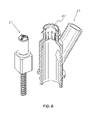
- FIGS. 8 through 10 depict one embodiment of the present invention in which three sealing functions are performed by two seal structures which are carried by the valve body of the valve-device, as opposed to being carried by a movable piston member of the valve device;
- FIGS. 11 through 12 depict one feature of the preferred piston tip end of the valve device of the present invention.
- FIGS. 13 through 23 depict an alternative embodiment of the present invention in which one seal member is carried by the vale body and another valve member is carried by the piston member;
- FIGS. 24 through 28 depict one process for constructing a valve in accordance with the present invention
- FIGS. 29–32 depict a second process for constructing a valve in accodance with the present invention.
- One concept of the present invention is to attach a static elastomeric circular seal to the top inside surface of the female luer in the valve body.
- the piston head can now be completely rigid. As soon as the piston head is depressed downward by a male luer, it disengages from the anti-bacterial static seal.
- This principle can be used in a variety of valve configurations (such as, without limitation, in-line valves, Y valves, etc.) and with a variety of valve mechanisms.
- FIG. 2 is perspective view of the valve in a disassembled, or exploded, and partial fragmentary form.
- valve body 21 includes a y-branch, making it a y-site valve.
- a central cavity 25 is defined therein. It is adapted in size and shape to carry piston 27 .
- Piston 27 includes a radially-reduced upper end 29 and a radially enlarged lower end 31 . It includes a tapered shoulder at the transition between he two portions. Piston 27 is biased upward by spring 33 .
- a seal, such as O-ring 35 is carried at the top of radially enlarged portion 31 , and it is adapted to mate with shoulder 37 of central cavity 25 .
- Female luer 39 is carried at the top of valve body 21 . It includes grooves 41 to allow fluid to pass into the central cavity when the luer valve is opened.
- a seal cavity 43 is formed in the upper portion of valve body 2 . It is adapted to receive a seal such as O-ring seal 45 .
- FIG. 3 depicts the valve in a closed condition.
- FIGS. 4 and 5 depict one alternative construction technique for the valve of the present invention.
- a uniform diameter opening 61 is provided at the upper end of valve body 21 .
- Elastomeric barrier seal 63 is provided.
- the elastomeric barrier seal is lowered into the upper end of valve body 21 .
- Heat or ultrasound may then be applied to create a heat or ultrasound deformation 65 of the upper end of valve body 21 to secure elastomeric barrier seal 63 .
- FIG. 5 This manufacturing process is depicted as a series of steps in FIGS. 24–28 .
- elastomeric barrier seal 63 is lowered into position relative to uniform diameter opening 61 .
- FIG. 24 elastomeric barrier seal 63 is lowered into position relative to uniform diameter opening 61 .
- FIG. 25 shows the elastomeric barrier seal 63 in place.
- a heater 75 is located adjacent the top of the valve housing 21 , in order to heat up the material.
- a forming tool 77 is pressed into the heated part. The forming tool 77 shapes and cools the part into its final from which is shown in FIG. 28 .
- FIGS. 6 and 7 depict another alternative construction technique for the valve of the present invention. As is shown in FIG. 6 , a double wall molding 67 may be utilized to secure elastomeric barrier in position. FIG. 7 depicts the valve in final assembled form.
- FIGS. 8 through 10 depict one embodiment of the present invention, in which an upper annular seal member is integral with the valve body and a second annular seal member is also integral with the valve body. Additionally, a third face seal is provided which is formed at the interface of a shoulder defined within the central fluid passageway and a shoulder which is formed on the piston member.
- the upper seal provides a primary seal
- the lower seal provides a backup sea, to prevent blood or fluid leakage when the piston is accidentally partially depressed.
- a face seal provides a “pressure seal”.
- the lower seal it is possible for the lower seal to be configured in a way so that it acts as a face seal and as the lower, backup seal.
- both seals can be integrally molded with the body in the same operation, the cost of assembling the moving seal to the piston is eliminated thus reducing manufacturing costs.
- FIG. 8 depicts a valve 101 , which composed of a valve body 103 and a piston 105 .
- the valve defines a female luer 109 which is adapted to mate with a male luer connector 111 .
- a central fluid passageway 104 is defined within valve body 103 .
- a y-branch passage is connected to the central fluid passageway 104 . This allows the mixing of fluids within the valve, and it is conventional.
- the upper-most seal, or “top” seal is seal 113 which is integral with the valve body 103 .
- seal 113 is an O-ring type seal which is formed from an elastomeric material, but which may be formed from other materials. It is carried in an annular cavity formed in the valve body 103 in the region of the valve 101 in which the male luer 111 first comes into contact with the female luer 109 .
- a second, lower seal 117 is provided at a lower location relative to the upper seal 113 .
- the lower seal 117 includes an annular seal 115 which is carried by the valve body 103 in position proximate the change in diameter of the central fluid passageway 104 of the valve body 103 . At this location a shoulder is defined by both the central fluid passageway 104 and the piston 105 .
- a third, face seal is defined by the engagement of the piston shoulder and the cavity shoulder.
- FIG. 8 shows the valve 101 in a fully closed condition.
- FIG. 9 depicts the same valve 101 in a partially open condition. In this condition, the upper seal 113 is open, the lower seal 117 is still effective, and the face seal 119 is not providing a strong pressure seal at this time.
- FIG. 10 depicts the same valve 101 in a fully open condition, with all three seals open.
- FIGS. 11 and 12 another embodiment of the present invention in which the lower valve is carried by the piston 105 .
- the face valve and the lower valve are separate structures. It also depicts another feature of the present invention which is carried at the tip 151 of the piston 105 . This feature may be utilized with any embodiment of the present invention.
- the valve body 105 includes seal cavity 112 which carries upper or “top” seal 113 , and seal cavity 118 which carries lower seal 117 .
- Tip 151 is a slightly conical, domed-shaped surface 153 , and it carries a plurality of raised ridges or “ribs”, such as ribs 155 , 157 , 159 . These ribs 155 , 157 , 159 extend along the direction of the conical surface and together form an apex which is generally centrally located relative to a centerline. The apex is adapted in size and shape to engage the central bore 108 of male luer 111 .
- FIG. 12 depicts how fluid flows from the male luer over the tip 151 of piston 105 .
- the ribs on the conical surface at the top of the piston contact the tip of the male luer and keep it a suitable distance from the surface to allow adequate flow between them.
- the conical tip ensures that, no matter which side the nurse approached the valve entrance, the tip of the male luer will not slide off, since it is meeting the rising conical surface of the top of the piston.
- FIG. 13 depicts an alternative embodiment of the valve of the present invention in which the top seal 203 is carried by the valve body 209 , the lower seal is carried by the piston 211 , and the face seal 207 is formed at the shoulder-to-shoulder interface of the piston and the central fluid passageway 215 which is formed in the valve body 209 .
- FIG. 14 depicts the valve 201 prior to opening. In this condition, the face seal 207 is now open, but lower seal 205 is still effective and preventing blood leakage.
- FIG. 15 depicts the valve 201 fully open.
- top a of piston may be depressed by accident, either by the patient or medical staff. Since the medical valve is connected to the patient's bloodstream, it is a very undesirable outcome. Such an occurrence can cause blood loss or the entry of bacteria into the patient.
- the valve of the present invention is designed to include a face seal which in the closed condition resists high pressures. As soon as the piston is depressed, this seal is no longer effective. This is useful because many medical procedures require that pressure be applied to the patient's vascular system. This can occur in the injection of dyes or medicines.
- the seal element is an O-ring seal which serves as the lower backup seal and the face seal. The backup seal remains in contact with the inner diameter of the valve housing for a brief interval after the upper seal is opened; this ensures that the valve is not opened inadvertently due to accidental contact.
- FIGS. 16 through 23 provide more detail about this embodiment.
- FIGS. 16 through 18 are exploded and partial longitudinal section views of valve 201 .
- FIGS. 19 through 23 are longitudinal section views of the same valve.
- FIG. 19 depicts the male luer 213 , the valve 201 , the piston 217 , the body 211 , the spring 219 , the central fluid passageway 215 , the top seal 203 and the lower seal 205 .
- FIGS. 19 through 21 depict the valve 201 in three operating conditions: fully closed, partially open, and fully open.
- FIG. 19 depicts the valve fully closed. Note that O-ring seal cavity is formed in the upper portion of valve body 211 , and an O-ring seal is disposed therein. Together this forms upper or “top” seal 203 . Additionally, an O-ring seal cavity is formed on piston 205 and an O-ring is disposed therein. Together these form lower seal 205 . When the valve 201 is fully closed, both O-rings make sealing contact with the inner surface of the valve body, so two seals are formed. Additionally, there is a face seal formed between the piston and the valve body.
- FIG. 20 depicts the valve 201 in a partially open condition.
- top seal 203 is “broken” but the lower seal 205 is still intact.
- the face seal is now less effective.
- the valve 210 is in a fully open condition, as top seal 203 and lower seal 205 are broken, and there is no face seal in place.
- FIGS. 22 and 23 depict details concerning the dimensions of the piston and location of the seals necessary to accomplish the present invention.
- the distance from the top of ribs 251 , 253 is “h”; accordingly, the distance from the middle of O-ring 261 and shoulder 263 is less than “h”. This ensures that the lower seal is still intact until after the first seal is broken.
- the piston for proper flow to occur, the piston must be depressed a minimum of “h” plus “Ma”, wherein Ma is the annular, desired flow area.
- the piston must be depressed an minimum of “Ma” plus “Mz”, wherein Mz is the minimum male luer depth in accordance with the specifications.
- FIG. 23 can be utilized to disclose the face seal of the present invention.
- two shoulders are formed in the inner surface of the valve body.
- One is shoulder 271 which is a transition between surface 283 and surface 273 .
- the second is shoulder 263 which is the transition between surface 273 and surface 293 .
- O-ring is adapted to engage surface 273 and form a seal with it.
- O-ring 261 will engage shoulder 271 and form a face seal with it.
Abstract
Description
- 1. The increased resistance problem mentioned in the case of a moving wiper seal disappears and, correspondingly, the return spring can be made lighter, thereby reducing the risk of accidental disconnection.
- 2. The tapered male luer experiences an increased interference with the static elastomeric seal as it penetrates inside the valve. This frictional force further reduces the risk of accidental disconnection.
- 3. Because the static seal contacts smooth surfaces at all times (the piston head when the valve is closed and the male luer when it is open) there is no risk of permanently or temporarily assuming a dimpled shape and thereby losing some of its effectiveness as an antibacterial barrier.
Claims (5)
Priority Applications (1)
| Application Number | Priority Date | Filing Date | Title |
|---|---|---|---|
| US10/453,677 US7160272B1 (en) | 2002-05-31 | 2003-06-02 | Y-site medical valve |
Applications Claiming Priority (2)
| Application Number | Priority Date | Filing Date | Title |
|---|---|---|---|
| US38516702P | 2002-05-31 | 2002-05-31 | |
| US10/453,677 US7160272B1 (en) | 2002-05-31 | 2003-06-02 | Y-site medical valve |
Publications (1)
| Publication Number | Publication Date |
|---|---|
| US7160272B1 true US7160272B1 (en) | 2007-01-09 |
Family
ID=37633420
Family Applications (1)
| Application Number | Title | Priority Date | Filing Date |
|---|---|---|---|
| US10/453,677 Expired - Fee Related US7160272B1 (en) | 2002-05-31 | 2003-06-02 | Y-site medical valve |
Country Status (1)
| Country | Link |
|---|---|
| US (1) | US7160272B1 (en) |
Cited By (64)
| Publication number | Priority date | Publication date | Assignee | Title |
|---|---|---|---|---|
| US20060027270A1 (en) * | 2004-08-09 | 2006-02-09 | Truitt Tim L | Connector with check valve and method of use |
| US20060293629A1 (en) * | 2001-11-13 | 2006-12-28 | Cote Andrew L Sr | Anti-drawback medical valve |
| US20080097407A1 (en) * | 2006-10-18 | 2008-04-24 | Michael Plishka | Luer activated device with compressible valve element |
| US20080116647A1 (en) * | 2006-10-18 | 2008-05-22 | Insulet Corporation | Environmental seal for fluid delivery device |
| US20080172003A1 (en) * | 2006-10-18 | 2008-07-17 | Michael Plishka | Luer activated device |
| US20080172005A1 (en) * | 2006-10-18 | 2008-07-17 | Jepson Steven C | Luer activated device with valve element under tension |
| US20080228172A1 (en) * | 2007-03-15 | 2008-09-18 | Petry Thomas S | Intravenous access safety device |
| US20090057589A1 (en) * | 2007-09-05 | 2009-03-05 | Thorne Consulting And Intellectual Property, Llc | Needle-free medical connector |
| US20090204080A1 (en) * | 2008-02-12 | 2009-08-13 | Baxter International Inc. | Two-way valve connector |
| US7753338B2 (en) | 2006-10-23 | 2010-07-13 | Baxter International Inc. | Luer activated device with minimal fluid displacement |
| EP2712653A3 (en) * | 2012-09-27 | 2015-08-26 | B. Braun Avitum AG | Fluid coupling |
| US20160235961A1 (en) * | 2013-09-25 | 2016-08-18 | Giuseppe Maffei | Needle-free connector |
| US9775981B2 (en) | 2013-03-15 | 2017-10-03 | Icu Medical, Inc. | Medical connector |
| US20180021560A1 (en) * | 2015-03-30 | 2018-01-25 | Terumo Kabushiki Kaisha | Medical connector |
| USD829897S1 (en) * | 2017-03-22 | 2018-10-02 | Asahi Intecc Co., Ltd. | Medical connector |
| US10105492B2 (en) | 2003-12-30 | 2018-10-23 | Icu Medical, Inc. | Medical connector with internal valve member movable within male luer projection |
| US10156306B2 (en) * | 2011-09-09 | 2018-12-18 | Icu Medical, Inc. | Axially engaging medical connector system with fluid-resistant mating interfaces |
| US10328207B2 (en) | 2006-06-22 | 2019-06-25 | Excelsior Medical Corporation | Antiseptic cap |
| US10342926B2 (en) | 2016-05-26 | 2019-07-09 | Insulet Corporation | Single dose drug delivery device |
| US10363372B2 (en) | 2016-08-12 | 2019-07-30 | Insulet Corporation | Plunger for drug delivery device |
| US10398887B2 (en) | 2007-05-16 | 2019-09-03 | Icu Medical, Inc. | Medical connector |
| US10441723B2 (en) | 2016-08-14 | 2019-10-15 | Insulet Corporation | Variable fill drug delivery device |
| US10478607B2 (en) | 2004-08-09 | 2019-11-19 | Carefusion 303, Inc. | Connector for transferring fluid and method of use |
| US10603440B2 (en) | 2017-01-19 | 2020-03-31 | Insulet Corporation | Cartridge hold-up volume reduction |
| CN111097085A (en) * | 2018-10-25 | 2020-05-05 | 陈戴毅 | Needle-free connector |
| US10695550B2 (en) | 2011-05-20 | 2020-06-30 | Excelsior Medical Corporation | Caps for needleless connectors |
| US10695485B2 (en) | 2017-03-07 | 2020-06-30 | Insulet Corporation | Very high volume user filled drug delivery device |
| US10716928B2 (en) | 2008-12-19 | 2020-07-21 | Icu Medical, Inc. | Medical connector with closeable luer connector |
| US10744316B2 (en) | 2016-10-14 | 2020-08-18 | Icu Medical, Inc. | Sanitizing caps for medical connectors |
| US10751478B2 (en) | 2016-10-07 | 2020-08-25 | Insulet Corporation | Multi-stage delivery system |
| US10780217B2 (en) | 2016-11-10 | 2020-09-22 | Insulet Corporation | Ratchet drive for on body delivery system |
| US10806919B2 (en) | 2011-05-23 | 2020-10-20 | Excelsior Medical Corporation | Antiseptic cap |
| US10821278B2 (en) | 2014-05-02 | 2020-11-03 | Excelsior Medical Corporation | Strip package for antiseptic cap |
| US10842982B2 (en) | 2005-07-06 | 2020-11-24 | Icu Medical, Inc. | Medical connector |
| US10874803B2 (en) | 2018-05-31 | 2020-12-29 | Insulet Corporation | Drug cartridge with drive system |
| US10898656B2 (en) | 2017-09-26 | 2021-01-26 | Insulet Corporation | Needle mechanism module for drug delivery device |
| US10973978B2 (en) | 2017-08-03 | 2021-04-13 | Insulet Corporation | Fluid flow regulation arrangements for drug delivery devices |
| US11045603B2 (en) | 2017-02-22 | 2021-06-29 | Insulet Corporation | Needle insertion mechanisms for drug containers |
| US11147931B2 (en) | 2017-11-17 | 2021-10-19 | Insulet Corporation | Drug delivery device with air and backflow elimination |
| US11229736B2 (en) | 2018-06-06 | 2022-01-25 | Insulet Corporation | Linear shuttle pump for drug delivery |
| US11229746B2 (en) | 2006-06-22 | 2022-01-25 | Excelsior Medical Corporation | Antiseptic cap |
| US11229741B2 (en) | 2012-03-30 | 2022-01-25 | Insulet Corporation | Fluid delivery device, transcutaneous access tool and fluid drive mechanism for use therewith |
| US11280327B2 (en) | 2017-08-03 | 2022-03-22 | Insulet Corporation | Micro piston pump |
| US11351353B2 (en) | 2008-10-27 | 2022-06-07 | Icu Medical, Inc. | Packaging container for antimicrobial caps |
| US11364341B2 (en) | 2015-11-25 | 2022-06-21 | Insulet Corporation | Wearable medication delivery device |
| US11369735B2 (en) | 2019-11-05 | 2022-06-28 | Insulet Corporation | Component positioning of a linear shuttle pump |
| US11389634B2 (en) | 2011-07-12 | 2022-07-19 | Icu Medical, Inc. | Device for delivery of antimicrobial agent into trans-dermal catheter |
| US11400195B2 (en) | 2018-11-07 | 2022-08-02 | Icu Medical, Inc. | Peritoneal dialysis transfer set with antimicrobial properties |
| US11433215B2 (en) | 2018-11-21 | 2022-09-06 | Icu Medical, Inc. | Antimicrobial device comprising a cap with ring and insert |
| US11446435B2 (en) | 2018-11-28 | 2022-09-20 | Insulet Corporation | Drug delivery shuttle pump system and valve assembly |
| US11517732B2 (en) | 2018-11-07 | 2022-12-06 | Icu Medical, Inc. | Syringe with antimicrobial properties |
| US11517733B2 (en) | 2017-05-01 | 2022-12-06 | Icu Medical, Inc. | Medical fluid connectors and methods for providing additives in medical fluid lines |
| US11534595B2 (en) | 2018-11-07 | 2022-12-27 | Icu Medical, Inc. | Device for delivering an antimicrobial composition into an infusion device |
| US11541220B2 (en) | 2018-11-07 | 2023-01-03 | Icu Medical, Inc. | Needleless connector with antimicrobial properties |
| US11541221B2 (en) | 2018-11-07 | 2023-01-03 | Icu Medical, Inc. | Tubing set with antimicrobial properties |
| US11559467B2 (en) | 2015-05-08 | 2023-01-24 | Icu Medical, Inc. | Medical connectors configured to receive emitters of therapeutic agents |
| US11786668B2 (en) | 2017-09-25 | 2023-10-17 | Insulet Corporation | Drug delivery devices, systems, and methods with force transfer elements |
| US11857763B2 (en) | 2016-01-14 | 2024-01-02 | Insulet Corporation | Adjusting insulin delivery rates |
| US11865299B2 (en) | 2008-08-20 | 2024-01-09 | Insulet Corporation | Infusion pump systems and methods |
| US11929158B2 (en) | 2016-01-13 | 2024-03-12 | Insulet Corporation | User interface for diabetes management system |
| USD1020794S1 (en) | 2018-04-02 | 2024-04-02 | Bigfoot Biomedical, Inc. | Medication delivery device with icons |
| US11944776B2 (en) | 2020-12-07 | 2024-04-02 | Icu Medical, Inc. | Peritoneal dialysis caps, systems and methods |
| USD1024090S1 (en) | 2019-01-09 | 2024-04-23 | Bigfoot Biomedical, Inc. | Display screen or portion thereof with graphical user interface associated with insulin delivery |
| US11969579B2 (en) | 2021-06-11 | 2024-04-30 | Insulet Corporation | Insulin delivery methods, systems and devices |
Citations (91)
| Publication number | Priority date | Publication date | Assignee | Title |
|---|---|---|---|---|
| US3566874A (en) | 1968-08-13 | 1971-03-02 | Nat Patent Dev Corp | Catheter |
| US3782382A (en) | 1972-02-03 | 1974-01-01 | K N Enterprises Inc | Means for blood administration and the like |
| US3889710A (en) | 1972-11-07 | 1975-06-17 | Julien H Brost | Check valve with elastomeric valve element |
| US3954121A (en) | 1975-03-17 | 1976-05-04 | The Weatherhead Company | Vent check valve |
| US4031891A (en) | 1975-11-03 | 1977-06-28 | Baxter Travenol Laboratories, Inc. | Air eliminating filter |
| US4063555A (en) | 1975-01-24 | 1977-12-20 | Aktiebolaget Stille-Werner | Cannula assembly |
| US4141379A (en) | 1977-05-16 | 1979-02-27 | Cutter Laboratories, Inc. | Check valve |
| US4222407A (en) | 1978-09-13 | 1980-09-16 | Baxter Travenol Laboratories, Inc. | One-way flex valve |
| US4236517A (en) | 1979-09-24 | 1980-12-02 | Alza Corporation | Patient-care apparatus with chemoprophylactic system |
| US4333457A (en) | 1981-02-09 | 1982-06-08 | Sterling Drug Inc. | Self-aspirating syringe with frictionally engaged locking collet |
| US4369812A (en) | 1981-02-18 | 1983-01-25 | Nypro Inc. | Control of fluid flow using precisely positioned disc |
| US4387879A (en) | 1978-04-19 | 1983-06-14 | Eduard Fresenius Chemisch Pharmazeutische Industrie Kg | Self-sealing connector for use with plastic cannulas and vessel catheters |
| US4447230A (en) | 1981-08-05 | 1984-05-08 | Quest Medical, Inc. | Intravenous administration set assembly |
| US4460367A (en) | 1977-06-09 | 1984-07-17 | Alza Corporation | Device containing biocide producing paraformalde and an acid |
| US4483287A (en) | 1982-05-10 | 1984-11-20 | Kysor Industrial Corporation | Mechanical engine protection system |
| US4512764A (en) | 1982-09-27 | 1985-04-23 | Wunsch Richard E | Manifold for controlling administration of multiple intravenous solutions and medications |
| US4515593A (en) | 1981-12-31 | 1985-05-07 | C. R. Bard, Inc. | Medical tubing having exterior hydrophilic coating for microbiocide absorption therein and method for using same |
| US4526140A (en) | 1982-05-10 | 1985-07-02 | Kysor Industrial Corporation | Mechanical engine protection system |
| US4529398A (en) | 1977-06-09 | 1985-07-16 | Wong Patrick S | Method for preventing contamination of catheter and drainage receptacle |
| US4556086A (en) | 1984-09-26 | 1985-12-03 | Burron Medical Inc. | Dual disc low pressure back-check valve |
| US4559036A (en) | 1983-12-14 | 1985-12-17 | Wunsch Richard E | Apparatus for controlling administration of multiple intravenous solutions and medications |
| US4581028A (en) | 1984-04-30 | 1986-04-08 | The Trustees Of Columbia University In The City Of New York | Infection-resistant materials and method of making same through use of sulfonamides |
| US4592920A (en) | 1983-05-20 | 1986-06-03 | Baxter Travenol Laboratories, Inc. | Method for the production of an antimicrobial catheter |
| US4601880A (en) | 1977-06-09 | 1986-07-22 | Alza Corporation | Urine container with biocidal activity |
| US4603152A (en) | 1982-11-05 | 1986-07-29 | Baxter Travenol Laboratories, Inc. | Antimicrobial compositions |
| US4610665A (en) | 1983-01-18 | 1986-09-09 | Terumo Kabushiki Kaisha | Medical instrument |
| US4626245A (en) | 1985-08-30 | 1986-12-02 | Cordis Corporation | Hemostatis valve comprising an elastomeric partition having opposed intersecting slits |
| US4673393A (en) | 1984-12-28 | 1987-06-16 | Terumo Kabushiki Kaisha | Medical instrument |
| US4677143A (en) | 1984-10-01 | 1987-06-30 | Baxter Travenol Laboratories, Inc. | Antimicrobial compositions |
| US4708870A (en) | 1985-06-03 | 1987-11-24 | E. I. Du Pont De Nemours And Company | Method for imparting antimicrobial activity from acrylics |
| US4758609A (en) | 1984-06-11 | 1988-07-19 | Morton Thiokol, Inc. | Microbiocidal compositions comprising an aryl alkanol and a microbiocidal compound dissolved therein |
| US4768518A (en) | 1985-10-01 | 1988-09-06 | Instrumentarium Corp. | Pressure control system and apparatus for the cuff of an automatic non-invasive blood pressure meter |
| US4795441A (en) | 1987-04-16 | 1989-01-03 | Bhatt Kunjlata M | Medication administration system |
| US4915688A (en) | 1987-12-03 | 1990-04-10 | Baxter International Inc. | Apparatus for administering solution to a patient |
| US4922954A (en) | 1988-03-04 | 1990-05-08 | Kelch Corp. | Bi-directional pressure relief vent for a fuel tank |
| US4933178A (en) | 1988-10-07 | 1990-06-12 | Biointerface Technologies, Inc. | Metal-based antimicrobial coating |
| US4946448A (en) | 1989-10-23 | 1990-08-07 | Kendall Mcgaw Laboratories, Inc. | Check valve for use with intravenous pump |
| US4988062A (en) | 1988-03-10 | 1991-01-29 | London Robert A | Apparatus, system and method for organizing and maintaining a plurality of medical catheters and the like |
| US5019096A (en) | 1988-02-11 | 1991-05-28 | Trustees Of Columbia University In The City Of New York | Infection-resistant compositions, medical devices and surfaces and methods for preparing and using same |
| US5020562A (en) | 1989-11-28 | 1991-06-04 | Imed Corporation | Multiline check valve assembly |
| US5049140A (en) | 1989-05-22 | 1991-09-17 | Firma Carl Freudenberg | Antimicrobial fitting for medical catheters and method for their application |
| US5057084A (en) | 1990-03-01 | 1991-10-15 | The Regents Of The University Of Michigan | Implantable infusion device |
| US5074334A (en) * | 1989-07-27 | 1991-12-24 | Terumo Kabushiki Kaisha | Multi-way cock |
| US5092842A (en) | 1987-05-08 | 1992-03-03 | Wilhelm Haselmeier Gmbh & Co. | Injection device with a cocking element and a second setting element |
| US5188591A (en) * | 1990-01-26 | 1993-02-23 | Dorsey Iii James H | Irrigation control valve for endoscopic instrument |
| US5190525A (en) | 1990-12-21 | 1993-03-02 | Abbott Laboratories | Drug infusion manifold |
| US5205834A (en) | 1990-09-04 | 1993-04-27 | Moorehead H Robert | Two-way outdwelling slit valving of medical liquid flow through a cannula and methods |
| US5288290A (en) * | 1991-09-25 | 1994-02-22 | Alcon Surgical, Inc. | Multi-ported valve assembly |
| US5308322A (en) | 1993-04-19 | 1994-05-03 | Tennican Patrick O | Central venous catheter access system |
| US5336192A (en) | 1991-11-27 | 1994-08-09 | Palestrant Aubrey M | Self-sealing valve device for angiographic catheters |
| US5353837A (en) * | 1986-03-04 | 1994-10-11 | Deka Products Limited Partnership | Quick-disconnect valve |
| WO1994022522A1 (en) | 1993-03-30 | 1994-10-13 | Medex, Inc. | Medical devices having antimicrobial properties and methods of making and using |
| US5356375A (en) | 1992-04-06 | 1994-10-18 | Namic U.S.A. Corporation | Positive pressure fluid delivery and waste removal system |
| US5429485A (en) | 1992-12-18 | 1995-07-04 | Minnesota Mining And Manufacturing Company | Plural inlet pumping cassette with integral manifold |
| US5431185A (en) | 1992-08-21 | 1995-07-11 | Pacific Device Inc. | Manifold for infusing medical fluids |
| US5439451A (en) * | 1994-03-22 | 1995-08-08 | B. Braun Medical, Inc. | Capless medical backcheck valve |
| US5535771A (en) * | 1994-08-10 | 1996-07-16 | Becton, Dickinson And Company | Valved PRN adapter for infusion devices |
| US5549651A (en) | 1994-05-25 | 1996-08-27 | Lynn; Lawrence A. | Luer-receiving medical valve and fluid transfer method |
| US5554373A (en) | 1993-11-05 | 1996-09-10 | Seabrook; Samuel G. | Compositions containing anti-microbial agents and methods for making and using same |
| US5567495A (en) | 1993-08-06 | 1996-10-22 | The Trustees Of Columbia University In The City Of New York | Infection resistant medical devices |
| US5618268A (en) | 1995-06-06 | 1997-04-08 | B. Braun Medical Inc. | Medical infusion devices and medicine delivery systems employing the same |
| US5676346A (en) * | 1995-05-16 | 1997-10-14 | Ivac Holdings, Inc. | Needleless connector valve |
| US5681468A (en) | 1993-12-20 | 1997-10-28 | Biopolymerix, Inc. | Filter coated with antimicrobial material |
| US5707366A (en) | 1989-01-18 | 1998-01-13 | Becton Dickinson And Company | Anti-infective and antithrombogenic medical articles and method for their preparation |
| US5738662A (en) | 1996-02-21 | 1998-04-14 | Pacific Device/Avail Medical Products, Inc. | Retrograde flow checked manifold for infusing medical fluids |
| US5744151A (en) | 1995-06-30 | 1998-04-28 | Capelli; Christopher C. | Silver-based pharmaceutical compositions |
| US5788215A (en) | 1995-12-29 | 1998-08-04 | Rymed Technologies | Medical intravenous administration line connectors having a luer or pressure activated valve |
| US5806551A (en) * | 1993-11-19 | 1998-09-15 | Novoste Corporation | Automatic fluid control valve |
| US5817325A (en) | 1996-10-28 | 1998-10-06 | Biopolymerix, Inc. | Contact-killing antimicrobial devices |
| US5848995A (en) | 1993-04-09 | 1998-12-15 | Walder; Anthony J. | Anti-infective medical article and method for its preparation |
| US5849311A (en) | 1996-10-28 | 1998-12-15 | Biopolymerix, Inc. | Contact-killing non-leaching antimicrobial materials |
| US5873731A (en) | 1995-10-20 | 1999-02-23 | Eagle Simulation, Inc. | Patient drug recognition system |
| US5873904A (en) | 1995-06-07 | 1999-02-23 | Cook Incorporated | Silver implantable medical device |
| US5877243A (en) | 1997-05-05 | 1999-03-02 | Icet, Inc. | Encrustation and bacterial resistant coatings for medical applications |
| US6009902A (en) * | 1997-11-12 | 2000-01-04 | Westinghouse Air Brake Company | Dual valve fitting for enabling quick measurement of pressure |
| US6099511A (en) * | 1999-03-19 | 2000-08-08 | Merit Medical Systems, Inc. | Manifold with check valve positioned within manifold body |
| US6117114A (en) * | 1998-05-07 | 2000-09-12 | Paradis; Joseph R. | Swabbable needleless valve adaptations |
| US6171287B1 (en) * | 1998-05-29 | 2001-01-09 | Lawrence A. Lynn | Luer receiver and method for fluid transfer |
| US6224579B1 (en) | 1999-03-31 | 2001-05-01 | The Trustees Of Columbia University In The City Of New York | Triclosan and silver compound containing medical devices |
| US6227413B1 (en) | 1996-10-18 | 2001-05-08 | Ing. Erich Pfeiffer Gmbh | Discharge apparatus with organic component active against microorganisms |
| US6245048B1 (en) * | 1996-12-16 | 2001-06-12 | Icu Medical, Inc. | Medical valve with positive flow characteristics |
| US6261271B1 (en) | 1989-01-18 | 2001-07-17 | Becton Dickinson And Company | Anti-infective and antithrombogenic medical articles and method for their preparation |
| US6273875B1 (en) | 1998-08-17 | 2001-08-14 | Edwards Lifesciences Corporation | Medical devices having improved antimicrobial/antithrombogenic properties |
| US6344035B1 (en) | 1998-04-27 | 2002-02-05 | Surmodics, Inc. | Bioactive agent release coating |
| US6364861B1 (en) | 1998-09-17 | 2002-04-02 | Porex Medical Products, Inc. | Multi-valve injection/aspiration manifold |
| US20020133124A1 (en) | 1999-07-27 | 2002-09-19 | Leinsing Karl R. | Needleless medical connector having antimicrobial agent |
| US20020147431A1 (en) * | 1996-12-16 | 2002-10-10 | Lopez George A. | Positive flow valve |
| US6482188B1 (en) * | 1999-10-01 | 2002-11-19 | Mission Medical Devices, Inc. | Nonvented needle-free injection valve |
| US6575187B2 (en) * | 1999-03-23 | 2003-06-10 | Entergris, Inc. | Three-way plastic valve |
| US6971999B2 (en) | 2001-11-14 | 2005-12-06 | Medical Instill Technologies, Inc. | Intradermal delivery device and method |
| US6991215B2 (en) * | 2001-08-23 | 2006-01-31 | Occupational & Medical Innovations, Ltd. | Valve for use with a syringe and which prevents backflow |
-
2003
- 2003-06-02 US US10/453,677 patent/US7160272B1/en not_active Expired - Fee Related
Patent Citations (93)
| Publication number | Priority date | Publication date | Assignee | Title |
|---|---|---|---|---|
| US3566874A (en) | 1968-08-13 | 1971-03-02 | Nat Patent Dev Corp | Catheter |
| US3782382A (en) | 1972-02-03 | 1974-01-01 | K N Enterprises Inc | Means for blood administration and the like |
| US3889710A (en) | 1972-11-07 | 1975-06-17 | Julien H Brost | Check valve with elastomeric valve element |
| US4063555A (en) | 1975-01-24 | 1977-12-20 | Aktiebolaget Stille-Werner | Cannula assembly |
| US3954121A (en) | 1975-03-17 | 1976-05-04 | The Weatherhead Company | Vent check valve |
| US4031891A (en) | 1975-11-03 | 1977-06-28 | Baxter Travenol Laboratories, Inc. | Air eliminating filter |
| US4141379A (en) | 1977-05-16 | 1979-02-27 | Cutter Laboratories, Inc. | Check valve |
| US4601880A (en) | 1977-06-09 | 1986-07-22 | Alza Corporation | Urine container with biocidal activity |
| US4529398A (en) | 1977-06-09 | 1985-07-16 | Wong Patrick S | Method for preventing contamination of catheter and drainage receptacle |
| US4460367A (en) | 1977-06-09 | 1984-07-17 | Alza Corporation | Device containing biocide producing paraformalde and an acid |
| US4387879A (en) | 1978-04-19 | 1983-06-14 | Eduard Fresenius Chemisch Pharmazeutische Industrie Kg | Self-sealing connector for use with plastic cannulas and vessel catheters |
| US4222407A (en) | 1978-09-13 | 1980-09-16 | Baxter Travenol Laboratories, Inc. | One-way flex valve |
| US4236517A (en) | 1979-09-24 | 1980-12-02 | Alza Corporation | Patient-care apparatus with chemoprophylactic system |
| US4333457A (en) | 1981-02-09 | 1982-06-08 | Sterling Drug Inc. | Self-aspirating syringe with frictionally engaged locking collet |
| US4369812A (en) | 1981-02-18 | 1983-01-25 | Nypro Inc. | Control of fluid flow using precisely positioned disc |
| US4447230A (en) | 1981-08-05 | 1984-05-08 | Quest Medical, Inc. | Intravenous administration set assembly |
| US4515593A (en) | 1981-12-31 | 1985-05-07 | C. R. Bard, Inc. | Medical tubing having exterior hydrophilic coating for microbiocide absorption therein and method for using same |
| US4526140A (en) | 1982-05-10 | 1985-07-02 | Kysor Industrial Corporation | Mechanical engine protection system |
| US4483287A (en) | 1982-05-10 | 1984-11-20 | Kysor Industrial Corporation | Mechanical engine protection system |
| US4512764A (en) | 1982-09-27 | 1985-04-23 | Wunsch Richard E | Manifold for controlling administration of multiple intravenous solutions and medications |
| US4603152A (en) | 1982-11-05 | 1986-07-29 | Baxter Travenol Laboratories, Inc. | Antimicrobial compositions |
| US4610665A (en) | 1983-01-18 | 1986-09-09 | Terumo Kabushiki Kaisha | Medical instrument |
| US4592920A (en) | 1983-05-20 | 1986-06-03 | Baxter Travenol Laboratories, Inc. | Method for the production of an antimicrobial catheter |
| US4559036A (en) | 1983-12-14 | 1985-12-17 | Wunsch Richard E | Apparatus for controlling administration of multiple intravenous solutions and medications |
| US4581028A (en) | 1984-04-30 | 1986-04-08 | The Trustees Of Columbia University In The City Of New York | Infection-resistant materials and method of making same through use of sulfonamides |
| US4758609A (en) | 1984-06-11 | 1988-07-19 | Morton Thiokol, Inc. | Microbiocidal compositions comprising an aryl alkanol and a microbiocidal compound dissolved therein |
| US4556086A (en) | 1984-09-26 | 1985-12-03 | Burron Medical Inc. | Dual disc low pressure back-check valve |
| US4677143A (en) | 1984-10-01 | 1987-06-30 | Baxter Travenol Laboratories, Inc. | Antimicrobial compositions |
| US4673393A (en) | 1984-12-28 | 1987-06-16 | Terumo Kabushiki Kaisha | Medical instrument |
| US4708870A (en) | 1985-06-03 | 1987-11-24 | E. I. Du Pont De Nemours And Company | Method for imparting antimicrobial activity from acrylics |
| US4626245A (en) | 1985-08-30 | 1986-12-02 | Cordis Corporation | Hemostatis valve comprising an elastomeric partition having opposed intersecting slits |
| US4768518A (en) | 1985-10-01 | 1988-09-06 | Instrumentarium Corp. | Pressure control system and apparatus for the cuff of an automatic non-invasive blood pressure meter |
| US5353837A (en) * | 1986-03-04 | 1994-10-11 | Deka Products Limited Partnership | Quick-disconnect valve |
| US4795441A (en) | 1987-04-16 | 1989-01-03 | Bhatt Kunjlata M | Medication administration system |
| US5092842A (en) | 1987-05-08 | 1992-03-03 | Wilhelm Haselmeier Gmbh & Co. | Injection device with a cocking element and a second setting element |
| US4915688A (en) | 1987-12-03 | 1990-04-10 | Baxter International Inc. | Apparatus for administering solution to a patient |
| US5019096A (en) | 1988-02-11 | 1991-05-28 | Trustees Of Columbia University In The City Of New York | Infection-resistant compositions, medical devices and surfaces and methods for preparing and using same |
| US4922954A (en) | 1988-03-04 | 1990-05-08 | Kelch Corp. | Bi-directional pressure relief vent for a fuel tank |
| US4988062A (en) | 1988-03-10 | 1991-01-29 | London Robert A | Apparatus, system and method for organizing and maintaining a plurality of medical catheters and the like |
| US4933178A (en) | 1988-10-07 | 1990-06-12 | Biointerface Technologies, Inc. | Metal-based antimicrobial coating |
| US6261271B1 (en) | 1989-01-18 | 2001-07-17 | Becton Dickinson And Company | Anti-infective and antithrombogenic medical articles and method for their preparation |
| US5707366A (en) | 1989-01-18 | 1998-01-13 | Becton Dickinson And Company | Anti-infective and antithrombogenic medical articles and method for their preparation |
| US5049140A (en) | 1989-05-22 | 1991-09-17 | Firma Carl Freudenberg | Antimicrobial fitting for medical catheters and method for their application |
| US5074334A (en) * | 1989-07-27 | 1991-12-24 | Terumo Kabushiki Kaisha | Multi-way cock |
| US4946448A (en) | 1989-10-23 | 1990-08-07 | Kendall Mcgaw Laboratories, Inc. | Check valve for use with intravenous pump |
| US5020562A (en) | 1989-11-28 | 1991-06-04 | Imed Corporation | Multiline check valve assembly |
| US5188591A (en) * | 1990-01-26 | 1993-02-23 | Dorsey Iii James H | Irrigation control valve for endoscopic instrument |
| US5057084A (en) | 1990-03-01 | 1991-10-15 | The Regents Of The University Of Michigan | Implantable infusion device |
| US5205834A (en) | 1990-09-04 | 1993-04-27 | Moorehead H Robert | Two-way outdwelling slit valving of medical liquid flow through a cannula and methods |
| US5190525A (en) | 1990-12-21 | 1993-03-02 | Abbott Laboratories | Drug infusion manifold |
| US5288290A (en) * | 1991-09-25 | 1994-02-22 | Alcon Surgical, Inc. | Multi-ported valve assembly |
| US5336192A (en) | 1991-11-27 | 1994-08-09 | Palestrant Aubrey M | Self-sealing valve device for angiographic catheters |
| US5356375A (en) | 1992-04-06 | 1994-10-18 | Namic U.S.A. Corporation | Positive pressure fluid delivery and waste removal system |
| US5431185A (en) | 1992-08-21 | 1995-07-11 | Pacific Device Inc. | Manifold for infusing medical fluids |
| US5429485A (en) | 1992-12-18 | 1995-07-04 | Minnesota Mining And Manufacturing Company | Plural inlet pumping cassette with integral manifold |
| WO1994022522A1 (en) | 1993-03-30 | 1994-10-13 | Medex, Inc. | Medical devices having antimicrobial properties and methods of making and using |
| US5848995A (en) | 1993-04-09 | 1998-12-15 | Walder; Anthony J. | Anti-infective medical article and method for its preparation |
| US5308322A (en) | 1993-04-19 | 1994-05-03 | Tennican Patrick O | Central venous catheter access system |
| US5567495A (en) | 1993-08-06 | 1996-10-22 | The Trustees Of Columbia University In The City Of New York | Infection resistant medical devices |
| US5554373A (en) | 1993-11-05 | 1996-09-10 | Seabrook; Samuel G. | Compositions containing anti-microbial agents and methods for making and using same |
| US5806551A (en) * | 1993-11-19 | 1998-09-15 | Novoste Corporation | Automatic fluid control valve |
| US5681468A (en) | 1993-12-20 | 1997-10-28 | Biopolymerix, Inc. | Filter coated with antimicrobial material |
| US5439451A (en) * | 1994-03-22 | 1995-08-08 | B. Braun Medical, Inc. | Capless medical backcheck valve |
| USRE37357E1 (en) | 1994-05-25 | 2001-09-04 | Lawrence A. Lynn | Luer-receiving medical valve and fluid transfer method |
| US5549651A (en) | 1994-05-25 | 1996-08-27 | Lynn; Lawrence A. | Luer-receiving medical valve and fluid transfer method |
| US5535771A (en) * | 1994-08-10 | 1996-07-16 | Becton, Dickinson And Company | Valved PRN adapter for infusion devices |
| US5676346A (en) * | 1995-05-16 | 1997-10-14 | Ivac Holdings, Inc. | Needleless connector valve |
| US5618268A (en) | 1995-06-06 | 1997-04-08 | B. Braun Medical Inc. | Medical infusion devices and medicine delivery systems employing the same |
| US5697904A (en) | 1995-06-06 | 1997-12-16 | B. Braun Medical Inc. | Medical infusion devices and medicine delivery systems employing the same |
| US5873904A (en) | 1995-06-07 | 1999-02-23 | Cook Incorporated | Silver implantable medical device |
| US5744151A (en) | 1995-06-30 | 1998-04-28 | Capelli; Christopher C. | Silver-based pharmaceutical compositions |
| US5873731A (en) | 1995-10-20 | 1999-02-23 | Eagle Simulation, Inc. | Patient drug recognition system |
| US5788215A (en) | 1995-12-29 | 1998-08-04 | Rymed Technologies | Medical intravenous administration line connectors having a luer or pressure activated valve |
| US5738662A (en) | 1996-02-21 | 1998-04-14 | Pacific Device/Avail Medical Products, Inc. | Retrograde flow checked manifold for infusing medical fluids |
| US6227413B1 (en) | 1996-10-18 | 2001-05-08 | Ing. Erich Pfeiffer Gmbh | Discharge apparatus with organic component active against microorganisms |
| US5817325A (en) | 1996-10-28 | 1998-10-06 | Biopolymerix, Inc. | Contact-killing antimicrobial devices |
| US5849311A (en) | 1996-10-28 | 1998-12-15 | Biopolymerix, Inc. | Contact-killing non-leaching antimicrobial materials |
| US20020147431A1 (en) * | 1996-12-16 | 2002-10-10 | Lopez George A. | Positive flow valve |
| US6245048B1 (en) * | 1996-12-16 | 2001-06-12 | Icu Medical, Inc. | Medical valve with positive flow characteristics |
| US5877243A (en) | 1997-05-05 | 1999-03-02 | Icet, Inc. | Encrustation and bacterial resistant coatings for medical applications |
| US6009902A (en) * | 1997-11-12 | 2000-01-04 | Westinghouse Air Brake Company | Dual valve fitting for enabling quick measurement of pressure |
| US6344035B1 (en) | 1998-04-27 | 2002-02-05 | Surmodics, Inc. | Bioactive agent release coating |
| US6117114A (en) * | 1998-05-07 | 2000-09-12 | Paradis; Joseph R. | Swabbable needleless valve adaptations |
| US6171287B1 (en) * | 1998-05-29 | 2001-01-09 | Lawrence A. Lynn | Luer receiver and method for fluid transfer |
| US6273875B1 (en) | 1998-08-17 | 2001-08-14 | Edwards Lifesciences Corporation | Medical devices having improved antimicrobial/antithrombogenic properties |
| US6364861B1 (en) | 1998-09-17 | 2002-04-02 | Porex Medical Products, Inc. | Multi-valve injection/aspiration manifold |
| US6099511A (en) * | 1999-03-19 | 2000-08-08 | Merit Medical Systems, Inc. | Manifold with check valve positioned within manifold body |
| US6575187B2 (en) * | 1999-03-23 | 2003-06-10 | Entergris, Inc. | Three-way plastic valve |
| US6224579B1 (en) | 1999-03-31 | 2001-05-01 | The Trustees Of Columbia University In The City Of New York | Triclosan and silver compound containing medical devices |
| US20020133124A1 (en) | 1999-07-27 | 2002-09-19 | Leinsing Karl R. | Needleless medical connector having antimicrobial agent |
| US6482188B1 (en) * | 1999-10-01 | 2002-11-19 | Mission Medical Devices, Inc. | Nonvented needle-free injection valve |
| US6991215B2 (en) * | 2001-08-23 | 2006-01-31 | Occupational & Medical Innovations, Ltd. | Valve for use with a syringe and which prevents backflow |
| US6971999B2 (en) | 2001-11-14 | 2005-12-06 | Medical Instill Technologies, Inc. | Intradermal delivery device and method |
Non-Patent Citations (15)
| Title |
|---|
| http://encarta.msn.com/find/Concise.asp?ti=06750000, Mar. 26, 2002. |
| http://www.aidsinfobbs.org/library/cdcsums/1993/012, Mar. 26, 2002. |
| http://www.bact.wisc.edu/microtextbook/ControlGrowth/sterilization.html, Mar. 26, 2002. |
| http://www.cdc.gov/ncidod/eid/vol7no2/mermel.htm, Mar. 26, 2002. |
| http://www.cdc.gov/ncidod/eid/vol7no2/wenzelG4.htm, Mar. 26, 2002. |
| http://www.cdc.gov/ncidod/hip/NNIS@nnis.htm, Mar. 26, 2002. |
| http://www.cdc.gov/niosh/hcwapp8.html, Mar. 26, 2002. |
| http://www.cidasal.es/mic<SUB>-</SUB>in.htm, Mar. 26, 2002. |
| http://www.edc.gov/drugresistance/miscellaneous/glossary.htm, Mar. 26, 2002. |
| http://www.macc.cc.mo.us/~biology/Phys<SUB>-</SUB>Chem<SUB>-</SUB>Control.html, Mar. 26, 2002. |
| http://www.panasonic.com.sg/consumer/index.cfm?type=products&product<SUB>-</SUB>id=56, Mar. 26, 2002. |
| http://www.silverinstitute.org/news/prhealth.htm, Mar. 26, 2002. |
| Michael J. Richards, et al., "Nosocomical Infections in Pediatric Intensive care Units in the United States", Pediatrics, vol. 103, No. 4, Apr. 1999. |
| Po-Ren Hsueh, et al., "Antimicrobial Drug Resistance in Pathogens Causing Nosocomial Infections at a University Hospital in Taiwan, 1981-1999", Emerging Infection Diseases, vol. 8, No. 1, Jan. 2002. |
| U.S. Appl. No. 60/385,167. |
Cited By (101)
| Publication number | Priority date | Publication date | Assignee | Title |
|---|---|---|---|---|
| US7837658B2 (en) | 2001-11-13 | 2010-11-23 | Nypro Inc. | Anti-drawback medical valve |
| US20060293629A1 (en) * | 2001-11-13 | 2006-12-28 | Cote Andrew L Sr | Anti-drawback medical valve |
| US8876784B2 (en) | 2001-11-13 | 2014-11-04 | Np Medical Inc. | Anti-drawback medical valve |
| US20110066119A1 (en) * | 2001-11-13 | 2011-03-17 | Np Medical Inc. | Anti-Drawback Medical Valve |
| US11266785B2 (en) | 2003-12-30 | 2022-03-08 | Icu Medical, Inc. | Medical connector with internal valve member movable within male projection |
| US10105492B2 (en) | 2003-12-30 | 2018-10-23 | Icu Medical, Inc. | Medical connector with internal valve member movable within male luer projection |
| US10039914B2 (en) | 2004-08-09 | 2018-08-07 | Carefusion 303, Inc. | Connector for transferring fluid |
| US20060027270A1 (en) * | 2004-08-09 | 2006-02-09 | Truitt Tim L | Connector with check valve and method of use |
| US8640725B2 (en) | 2004-08-09 | 2014-02-04 | Carefusion 303, Inc. | Connector for transferring fluid and method of use |
| US7600530B2 (en) * | 2004-08-09 | 2009-10-13 | Medegen, Inc. | Connector with check valve and method of use |
| US20090299300A1 (en) * | 2004-08-09 | 2009-12-03 | Medegen, Inc. | Connector for Transferring Fluid and Method of Use |
| US10842984B2 (en) | 2004-08-09 | 2020-11-24 | Carefusion 303, Inc. | Connector for transferring fluid |
| US20110152787A1 (en) * | 2004-08-09 | 2011-06-23 | Carefusion 303, Inc. | Connector for transferring fluid and method of use |
| US9393398B2 (en) | 2004-08-09 | 2016-07-19 | Carefusion 303, Inc. | Connector for transferring fluid and method of use |
| US10478607B2 (en) | 2004-08-09 | 2019-11-19 | Carefusion 303, Inc. | Connector for transferring fluid and method of use |
| US10940306B2 (en) | 2004-08-09 | 2021-03-09 | Carefusion 303, Inc. | Connector for transferring fluid and method of use |
| US7909056B2 (en) | 2004-08-09 | 2011-03-22 | Carefusion 303, Inc. | Connector for transferring fluid and method of use |
| US10842982B2 (en) | 2005-07-06 | 2020-11-24 | Icu Medical, Inc. | Medical connector |
| US11229746B2 (en) | 2006-06-22 | 2022-01-25 | Excelsior Medical Corporation | Antiseptic cap |
| US10328207B2 (en) | 2006-06-22 | 2019-06-25 | Excelsior Medical Corporation | Antiseptic cap |
| US11684720B2 (en) | 2006-06-22 | 2023-06-27 | Excelsior Medical Corporation | Antiseptic cap that releases a gas such as nitric oxide |
| US20080172003A1 (en) * | 2006-10-18 | 2008-07-17 | Michael Plishka | Luer activated device |
| US20080116647A1 (en) * | 2006-10-18 | 2008-05-22 | Insulet Corporation | Environmental seal for fluid delivery device |
| US20080097407A1 (en) * | 2006-10-18 | 2008-04-24 | Michael Plishka | Luer activated device with compressible valve element |
| US8221363B2 (en) | 2006-10-18 | 2012-07-17 | Baxter Healthcare S.A. | Luer activated device with valve element under tension |
| US7981090B2 (en) | 2006-10-18 | 2011-07-19 | Baxter International Inc. | Luer activated device |
| US20080172005A1 (en) * | 2006-10-18 | 2008-07-17 | Jepson Steven C | Luer activated device with valve element under tension |
| US7771412B2 (en) * | 2006-10-18 | 2010-08-10 | Insulet Corporation | Environmental seal for fluid delivery device |
| US7753338B2 (en) | 2006-10-23 | 2010-07-13 | Baxter International Inc. | Luer activated device with minimal fluid displacement |
| US20080228172A1 (en) * | 2007-03-15 | 2008-09-18 | Petry Thomas S | Intravenous access safety device |
| US11786715B2 (en) | 2007-05-16 | 2023-10-17 | Icu Medical, Inc. | Medical connector |
| US10398887B2 (en) | 2007-05-16 | 2019-09-03 | Icu Medical, Inc. | Medical connector |
| US7841581B2 (en) | 2007-09-05 | 2010-11-30 | Thorne Consulting & Intellectual Property, LLC | Needle-free medical connector |
| US20090057589A1 (en) * | 2007-09-05 | 2009-03-05 | Thorne Consulting And Intellectual Property, Llc | Needle-free medical connector |
| US20090204080A1 (en) * | 2008-02-12 | 2009-08-13 | Baxter International Inc. | Two-way valve connector |
| US11160932B2 (en) | 2008-06-19 | 2021-11-02 | Excelsior Medical Corporation | Antiseptic cap that releases a gas such as nitric oxide |
| US11865299B2 (en) | 2008-08-20 | 2024-01-09 | Insulet Corporation | Infusion pump systems and methods |
| US11351353B2 (en) | 2008-10-27 | 2022-06-07 | Icu Medical, Inc. | Packaging container for antimicrobial caps |
| US11478624B2 (en) | 2008-12-19 | 2022-10-25 | Icu Medical, Inc. | Medical connector with closeable luer connector |
| US10716928B2 (en) | 2008-12-19 | 2020-07-21 | Icu Medical, Inc. | Medical connector with closeable luer connector |
| US10695550B2 (en) | 2011-05-20 | 2020-06-30 | Excelsior Medical Corporation | Caps for needleless connectors |
| US10806919B2 (en) | 2011-05-23 | 2020-10-20 | Excelsior Medical Corporation | Antiseptic cap |
| US11826539B2 (en) | 2011-07-12 | 2023-11-28 | Icu Medical, Inc. | Device for delivery of antimicrobial agent into a medical device |
| US11389634B2 (en) | 2011-07-12 | 2022-07-19 | Icu Medical, Inc. | Device for delivery of antimicrobial agent into trans-dermal catheter |
| US11168818B2 (en) | 2011-09-09 | 2021-11-09 | Icu Medical, Inc. | Axially engaging medical connector system that inhibits fluid penetration between mating surfaces |
| US11808389B2 (en) | 2011-09-09 | 2023-11-07 | Icu Medical, Inc. | Medical connectors with luer-incompatible connection portions |
| US10697570B2 (en) | 2011-09-09 | 2020-06-30 | Icu Medical, Inc. | Axially engaging medical connector system with diminished fluid remnants |
| US10156306B2 (en) * | 2011-09-09 | 2018-12-18 | Icu Medical, Inc. | Axially engaging medical connector system with fluid-resistant mating interfaces |
| US11229741B2 (en) | 2012-03-30 | 2022-01-25 | Insulet Corporation | Fluid delivery device, transcutaneous access tool and fluid drive mechanism for use therewith |
| US11684713B2 (en) | 2012-03-30 | 2023-06-27 | Insulet Corporation | Fluid delivery device, transcutaneous access tool and insertion mechanism for use therewith |
| EP2712653A3 (en) * | 2012-09-27 | 2015-08-26 | B. Braun Avitum AG | Fluid coupling |
| US10668268B2 (en) | 2013-03-15 | 2020-06-02 | Icu Medical, Inc. | Medical connector |
| US11786716B2 (en) | 2013-03-15 | 2023-10-17 | Icu Medical, Inc. | Medical connector |
| US9775981B2 (en) | 2013-03-15 | 2017-10-03 | Icu Medical, Inc. | Medical connector |
| US20160235961A1 (en) * | 2013-09-25 | 2016-08-18 | Giuseppe Maffei | Needle-free connector |
| US10821278B2 (en) | 2014-05-02 | 2020-11-03 | Excelsior Medical Corporation | Strip package for antiseptic cap |
| US20180021560A1 (en) * | 2015-03-30 | 2018-01-25 | Terumo Kabushiki Kaisha | Medical connector |
| US10688293B2 (en) * | 2015-03-30 | 2020-06-23 | Terumo Kabushiki Kaisha | Medical connector |
| US11559467B2 (en) | 2015-05-08 | 2023-01-24 | Icu Medical, Inc. | Medical connectors configured to receive emitters of therapeutic agents |
| US11364341B2 (en) | 2015-11-25 | 2022-06-21 | Insulet Corporation | Wearable medication delivery device |
| US11929158B2 (en) | 2016-01-13 | 2024-03-12 | Insulet Corporation | User interface for diabetes management system |
| US11857763B2 (en) | 2016-01-14 | 2024-01-02 | Insulet Corporation | Adjusting insulin delivery rates |
| US10363374B2 (en) | 2016-05-26 | 2019-07-30 | Insulet Corporation | Multi-dose drug delivery device |
| US10342926B2 (en) | 2016-05-26 | 2019-07-09 | Insulet Corporation | Single dose drug delivery device |
| US10363372B2 (en) | 2016-08-12 | 2019-07-30 | Insulet Corporation | Plunger for drug delivery device |
| US10441723B2 (en) | 2016-08-14 | 2019-10-15 | Insulet Corporation | Variable fill drug delivery device |
| US10561797B2 (en) | 2016-08-14 | 2020-02-18 | Insulet Corporation | Drug delivery device with indicator |
| US11439765B2 (en) | 2016-08-14 | 2022-09-13 | Insulet Corporation | Variable fill drug delivery device |
| US11497856B2 (en) | 2016-08-14 | 2022-11-15 | Insulet Corporation | Drug delivery device with indicator |
| US10751478B2 (en) | 2016-10-07 | 2020-08-25 | Insulet Corporation | Multi-stage delivery system |
| US11497904B2 (en) | 2016-10-14 | 2022-11-15 | Icu Medical, Inc. | Sanitizing caps for medical connectors |
| US10744316B2 (en) | 2016-10-14 | 2020-08-18 | Icu Medical, Inc. | Sanitizing caps for medical connectors |
| US10780217B2 (en) | 2016-11-10 | 2020-09-22 | Insulet Corporation | Ratchet drive for on body delivery system |
| US10603440B2 (en) | 2017-01-19 | 2020-03-31 | Insulet Corporation | Cartridge hold-up volume reduction |
| US11633541B2 (en) | 2017-01-19 | 2023-04-25 | Insulet Corporation | Cartridge hold-up volume reduction |
| US11045603B2 (en) | 2017-02-22 | 2021-06-29 | Insulet Corporation | Needle insertion mechanisms for drug containers |
| US10695485B2 (en) | 2017-03-07 | 2020-06-30 | Insulet Corporation | Very high volume user filled drug delivery device |
| USD829897S1 (en) * | 2017-03-22 | 2018-10-02 | Asahi Intecc Co., Ltd. | Medical connector |
| US11517733B2 (en) | 2017-05-01 | 2022-12-06 | Icu Medical, Inc. | Medical fluid connectors and methods for providing additives in medical fluid lines |
| US10973978B2 (en) | 2017-08-03 | 2021-04-13 | Insulet Corporation | Fluid flow regulation arrangements for drug delivery devices |
| US11280327B2 (en) | 2017-08-03 | 2022-03-22 | Insulet Corporation | Micro piston pump |
| US11786668B2 (en) | 2017-09-25 | 2023-10-17 | Insulet Corporation | Drug delivery devices, systems, and methods with force transfer elements |
| US10898656B2 (en) | 2017-09-26 | 2021-01-26 | Insulet Corporation | Needle mechanism module for drug delivery device |
| US11147931B2 (en) | 2017-11-17 | 2021-10-19 | Insulet Corporation | Drug delivery device with air and backflow elimination |
| USD1020794S1 (en) | 2018-04-02 | 2024-04-02 | Bigfoot Biomedical, Inc. | Medication delivery device with icons |
| US10874803B2 (en) | 2018-05-31 | 2020-12-29 | Insulet Corporation | Drug cartridge with drive system |
| US11229736B2 (en) | 2018-06-06 | 2022-01-25 | Insulet Corporation | Linear shuttle pump for drug delivery |
| CN111097085A (en) * | 2018-10-25 | 2020-05-05 | 陈戴毅 | Needle-free connector |
| US11123534B2 (en) * | 2018-10-25 | 2021-09-21 | Tai-Yi CHEN | Needle-free connector |
| CN111097085B (en) * | 2018-10-25 | 2022-08-12 | 陈戴毅 | Needle-free connector |
| US11517732B2 (en) | 2018-11-07 | 2022-12-06 | Icu Medical, Inc. | Syringe with antimicrobial properties |
| US11541220B2 (en) | 2018-11-07 | 2023-01-03 | Icu Medical, Inc. | Needleless connector with antimicrobial properties |
| US11534595B2 (en) | 2018-11-07 | 2022-12-27 | Icu Medical, Inc. | Device for delivering an antimicrobial composition into an infusion device |
| US11400195B2 (en) | 2018-11-07 | 2022-08-02 | Icu Medical, Inc. | Peritoneal dialysis transfer set with antimicrobial properties |
| US11541221B2 (en) | 2018-11-07 | 2023-01-03 | Icu Medical, Inc. | Tubing set with antimicrobial properties |
| US11433215B2 (en) | 2018-11-21 | 2022-09-06 | Icu Medical, Inc. | Antimicrobial device comprising a cap with ring and insert |
| US11446435B2 (en) | 2018-11-28 | 2022-09-20 | Insulet Corporation | Drug delivery shuttle pump system and valve assembly |
| USD1024090S1 (en) | 2019-01-09 | 2024-04-23 | Bigfoot Biomedical, Inc. | Display screen or portion thereof with graphical user interface associated with insulin delivery |
| US11369735B2 (en) | 2019-11-05 | 2022-06-28 | Insulet Corporation | Component positioning of a linear shuttle pump |
| US11944776B2 (en) | 2020-12-07 | 2024-04-02 | Icu Medical, Inc. | Peritoneal dialysis caps, systems and methods |
| US11969579B2 (en) | 2021-06-11 | 2024-04-30 | Insulet Corporation | Insulin delivery methods, systems and devices |
Similar Documents
| Publication | Publication Date | Title |
|---|---|---|
| US7160272B1 (en) | Y-site medical valve | |
| US5967490A (en) | Catheter hubs having a valve | |
| US6299132B1 (en) | Reflux valve | |
| US6609696B2 (en) | Male luer valve | |
| JP4469802B2 (en) | Needleless connector valve | |
| US20230166093A1 (en) | Catheter valves | |
| US8177760B2 (en) | Valved connector | |
| US5360413A (en) | Needleless access device | |
| US5215538A (en) | Connector-activated in-line valve | |
| US6892998B2 (en) | Medical valve and method of assembling the same | |
| US6585229B2 (en) | Medical nozzle securing apparatus | |
| US8876784B2 (en) | Anti-drawback medical valve | |
| US7993328B2 (en) | Self-sealing male luer connector with multiple seals | |
| AU2002359895B2 (en) | Slit-type swabable valve | |
| US7329249B2 (en) | Needleless Luer activated medical connector | |
| US6808161B1 (en) | Connector | |
| US5405323A (en) | Catheter check valve assembly | |
| US5921264A (en) | Swabbable needleless valve | |
| US5342326A (en) | Capless medical valve | |
| US20070083162A1 (en) | Valve for intravenous catheter | |
| WO1997031676A2 (en) | Valve assembly for medical uses | |
| CA2374846C (en) | Needle-less luer activated medical connector | |
| US20230381486A1 (en) | Needleless connector with valve pivot support | |
| EP1434620B1 (en) | Male luer valve | |
| US20020013556A1 (en) | Swabbable luer-activated valve |
Legal Events
| Date | Code | Title | Description |
|---|---|---|---|
| AS | Assignment |
Owner name: ELCAM PLASTIC, ISRAEL Free format text: ASSIGNMENT OF ASSIGNORS INTEREST;ASSIGNORS:VIDAL, CLAUDE A.;REDMOND, RUSSELL J.;CHANDOS, DAVID A.;REEL/FRAME:014807/0341;SIGNING DATES FROM 20030922 TO 20030923 |
|
| AS | Assignment |
Owner name: ELCAM PLASTIC, ISRAEL Free format text: ASSIGNMENT OF ASSIGNORS INTEREST;ASSIGNOR:EYAL, RONEN;REEL/FRAME:014846/0880 Effective date: 20031219 |
|
| FEPP | Fee payment procedure |
Free format text: PAYOR NUMBER ASSIGNED (ORIGINAL EVENT CODE: ASPN); ENTITY STATUS OF PATENT OWNER: LARGE ENTITY |
|
| FPAY | Fee payment |
Year of fee payment: 4 |
|
| FEPP | Fee payment procedure |
Free format text: PAT HOLDER NO LONGER CLAIMS SMALL ENTITY STATUS, ENTITY STATUS SET TO UNDISCOUNTED (ORIGINAL EVENT CODE: STOL); ENTITY STATUS OF PATENT OWNER: LARGE ENTITY |
|
| FPAY | Fee payment |
Year of fee payment: 8 |
|
| FEPP | Fee payment procedure |
Free format text: MAINTENANCE FEE REMINDER MAILED (ORIGINAL EVENT CODE: REM.); ENTITY STATUS OF PATENT OWNER: LARGE ENTITY |
|
| LAPS | Lapse for failure to pay maintenance fees |
Free format text: PATENT EXPIRED FOR FAILURE TO PAY MAINTENANCE FEES (ORIGINAL EVENT CODE: EXP.); ENTITY STATUS OF PATENT OWNER: LARGE ENTITY |
|
| STCH | Information on status: patent discontinuation |
Free format text: PATENT EXPIRED DUE TO NONPAYMENT OF MAINTENANCE FEES UNDER 37 CFR 1.362 |
|
| FP | Lapsed due to failure to pay maintenance fee |
Effective date: 20190109 |