US7162290B1 - Method and apparatus for blood glucose testing from a reversible infusion line - Google Patents
Method and apparatus for blood glucose testing from a reversible infusion line Download PDFInfo
- Publication number
- US7162290B1 US7162290B1 US11/228,827 US22882705A US7162290B1 US 7162290 B1 US7162290 B1 US 7162290B1 US 22882705 A US22882705 A US 22882705A US 7162290 B1 US7162290 B1 US 7162290B1
- Authority
- US
- United States
- Prior art keywords
- blood
- testing
- patient
- infusion
- chamber
- Prior art date
- Legal status (The legal status is an assumption and is not a legal conclusion. Google has not performed a legal analysis and makes no representation as to the accuracy of the status listed.)
- Expired - Fee Related
Links
Images


Classifications
-
- A—HUMAN NECESSITIES
- A61—MEDICAL OR VETERINARY SCIENCE; HYGIENE
- A61B—DIAGNOSIS; SURGERY; IDENTIFICATION
- A61B5/00—Measuring for diagnostic purposes; Identification of persons
- A61B5/68—Arrangements of detecting, measuring or recording means, e.g. sensors, in relation to patient
-
- A—HUMAN NECESSITIES
- A61—MEDICAL OR VETERINARY SCIENCE; HYGIENE
- A61B—DIAGNOSIS; SURGERY; IDENTIFICATION
- A61B5/00—Measuring for diagnostic purposes; Identification of persons
- A61B5/145—Measuring characteristics of blood in vivo, e.g. gas concentration, pH value; Measuring characteristics of body fluids or tissues, e.g. interstitial fluid, cerebral tissue
- A61B5/1486—Measuring characteristics of blood in vivo, e.g. gas concentration, pH value; Measuring characteristics of body fluids or tissues, e.g. interstitial fluid, cerebral tissue using enzyme electrodes, e.g. with immobilised oxidase
-
- A—HUMAN NECESSITIES
- A61—MEDICAL OR VETERINARY SCIENCE; HYGIENE
- A61M—DEVICES FOR INTRODUCING MEDIA INTO, OR ONTO, THE BODY; DEVICES FOR TRANSDUCING BODY MEDIA OR FOR TAKING MEDIA FROM THE BODY; DEVICES FOR PRODUCING OR ENDING SLEEP OR STUPOR
- A61M2205/00—General characteristics of the apparatus
- A61M2205/33—Controlling, regulating or measuring
- A61M2205/3306—Optical measuring means
- A61M2205/331—Optical measuring means used as turbidity change detectors, e.g. for priming-blood or plasma-hemoglubine-interface detection
-
- A—HUMAN NECESSITIES
- A61—MEDICAL OR VETERINARY SCIENCE; HYGIENE
- A61M—DEVICES FOR INTRODUCING MEDIA INTO, OR ONTO, THE BODY; DEVICES FOR TRANSDUCING BODY MEDIA OR FOR TAKING MEDIA FROM THE BODY; DEVICES FOR PRODUCING OR ENDING SLEEP OR STUPOR
- A61M2230/00—Measuring parameters of the user
- A61M2230/20—Blood composition characteristics
- A61M2230/201—Glucose concentration
-
- A—HUMAN NECESSITIES
- A61—MEDICAL OR VETERINARY SCIENCE; HYGIENE
- A61M—DEVICES FOR INTRODUCING MEDIA INTO, OR ONTO, THE BODY; DEVICES FOR TRANSDUCING BODY MEDIA OR FOR TAKING MEDIA FROM THE BODY; DEVICES FOR PRODUCING OR ENDING SLEEP OR STUPOR
- A61M5/00—Devices for bringing media into the body in a subcutaneous, intra-vascular or intramuscular way; Accessories therefor, e.g. filling or cleaning devices, arm-rests
- A61M5/14—Infusion devices, e.g. infusing by gravity; Blood infusion; Accessories therefor
- A61M5/142—Pressure infusion, e.g. using pumps
- A61M5/14212—Pumping with an aspiration and an expulsion action
- A61M5/14232—Roller pumps
Definitions
- This invention relates to blood glucose testing in critically ill patients.
- the need for a convenient and easily applied method of glucose monitoring in the Intensive Care Unit became evident after the landmark study of Van den Berghe and colleagues published in the Nov. 8, 2001 issue of The New England Journal of Medicine.
- Intensive treatment with insulin requires knowledge of patient blood sugar levels which presently involves obtaining either an arterial or a venous blood sample or pricking the patient's finger from time to time to obtain a capillary blood sample. Capillary samples are placed on a strip and read using a home-type glucose meter. All of these methods require considerable nurse or technician time. In the U.S. at present only 20% to 30% of patients in the ICU have arterial lines. Many patients, especially non-diabetics, find repeated finger sticks objectionable. Furthermore, intermittent blood samples may not be done often enough to give an accurate picture of blood sugar levels.
- Parker in U.S. Pat. No. 4,573,968 describes a system in which an infusion pump reverses direction to draw a patient blood sample through a catheter into contact with one or more electrochemical sensors.
- a compact cassette near the patient carries the sensors.
- the present invention eliminates the difficulties and complexities of previously described devices using a novel method of blood sampling located close to the catheterized artery or vein.
- a problem encountered in reversing an infusion line for sampling is determining how much blood should be withdrawn in order to be certain that pure undiluted blood is in contact with the sensor. This problem is discussed in U.S. Pat. No. 5,758,643 by Wong and Associates who attempt to solve the problem with the sensors themselves and particularly a calcium sensor which presumably will register a blood calcium in a normal range when undiluted blood has reached the sensing area. This method, while fairly satisfactory, may be somewhat inaccurate unless the patient's actual blood calcium level is exactly known. Also, there may be some delay between the time an undiluted sample reaches the sensing area and the time that a normal value is registered by the sensor and transmitted to the monitor which contains the pump. As a result, an unnecessarily large amount of blood may be withdrawn prior to stopping the peristaltic pump which is pumping in a retrograde manner to remove blood from the patient's catheter.
- the present invention discloses a novel method of halting the withdrawal of blood at the proper time so that a pure undiluted sample is presented to the sensor and ensures that no more than the necessary amount of blood is withdrawn.
- at least one, and for optimum performance two, LED/photodetector pairs are placed adjacent to the sampling chamber.
- the change from clear fluid to blood within the sampling chamber will cause a fairly sudden drop in the amount of light crossing the chamber since red cells will block considerable light in contrast to ordinary infusion fluid which is clear.
- the area of transition will be smeared out to a greater or lesser extent depending on the speed of the infusion and the size of the catheterized blood vessel.
- the transition area may extend for 10 to 20 cm up the blood vessel. If very little fluid was being infused, the withdrawal of a fluid column of just a few centimeters may suffice to place a pure blood sample into the sampling chamber.
- the disposable device with an LED/photodetector pair at each end of the sampling chamber, can readily detect when pure or undiluted blood fills the entire chamber because light reaching the photodetectors will be equivalent. It is at this moment, when equal amounts of light are received by the photodiodes, that the reverse motion of the peristaltic pump inside the bedside monitor can be stopped and the blood level of glucose tested.
- the peristaltic pump is again run in the normal forward direction to resume the infusion at the rate set by the caregiver.
- the present invention contains no expensive parts and can be made economically to allow wide use of the invention among critically ill hospitalized patients.
- the disposable test unit is relatively small and can be worn with comfort by the patient on the mid-forearm with the vessel catheter crossing the wrist to be inserted, in most cases, in a small vein on the back of the hand. Catheters of this type are commonly used for infusion lines and can be inserted by virtually all medical personnel who care for the critically ill.
- the catheter may be inserted elsewhere as well and the device can be used with arterial lines or central venous catheters. It is particularly useful in the latter case since dilution of venous blood in a central line may extend quite high up the arm. Regardless of the amount of dilution, the invention will be able to discern when a pure blood sample has reached the sampling chamber.
- the disposable test unit is built up from four layers of plastic and, when the layers are joined in final assembly, the device measures approximately 56 mm ⁇ 30 mm ⁇ 11 mm (2.25 ⁇ 1.25 ⁇ 0.440 inches).
- the layers are each 2.5 to 3.0 mm thick and allow features such as the sampling chamber to be molded into the thin layers of plastic.
- the flex circuit carrying the glucose sensor is located between layers 2 and 3 .
- the flex circuit carrying the LEDs is mounted between layers 1 and 2
- the flex circuit carrying the photodetectors is mounted between layers 3 and 4 .
- the four layers are welded together ultrasonically to produce in the final assembly a water tight hermetically sealed device.
- the glucose sensing area of the disposable device contains a glucose oxidase electrode with an active area of about 25 square millimeters.
- the glucose electrode is affixed to the distal area of the flex circuit and is covered by a thin polyurethane membrane which prevents cells and proteins from interfering with the action of the enzyme.
- An advantage of sampling intermittently, for example once every five minutes, is that during the period of ordinary fluid infusion, the membrane is cleared of cells and proteins which may have temporarily lodged on the membrane but are washed off by the infusion fluid between tests so that the possibility of membrane clogging by proteins or cells is greatly reduced.
- a suitable glucose oxidase electrode for such a flex circuit is made by Conductive Technologies of York, Pa.
- the disposable test unit is provided on its front surface with a male Luer fitting to take the female end of a polyethylene blood vessel catheter.
- the infusion line and electric cable carrying the electric leads are attached to the opposite face of the test unit with the infusion line being terminated at a drip chamber which inserts into a standard IV fluid bag.
- the infusion line is provided near its upper extremity with a short segment of soft silicone tubing to facilitate its use with a peristaltic pump.
- a door at the front of the monitor allows the caregiver to place the silicone portion of the infusion tubing next to the pump roller, and closure of the door on the front of the monitor locks the tubing in place against the roller wheel of the pump.
- a small peristaltic pump suitable for this application is made by Watson-Marlow Bredel of Commerce, Colo.
- Calibration can be accomplished daily or as often as needed by stopping the pump and injecting calibration fluid into the sampling chamber through a Luer-activated valve close to the chamber.
- the glucose electrode reads the glucose value of the solution and, if necessary, resets the electronic look-up table in the monitor to reflect the known value of the calibration solution.
- a primary object of the invention is to provide a low cost, disposable and simple device for automatically monitoring blood glucose levels in hospitalized patients.
- a further object of the invention is to provide a simple but yet reliable system for determining when an undiluted sample of blood is present in a test chamber prior to testing the sample for its blood glucose level.
- FIG. 1 is a perspective view of a portion of the device attached to a patient's forearm, showing a catheter inserted into a patient blood vessel;
- FIG. 2 is an overall perspective view showing the present invention attached to a hospitalized patient
- FIG. 3 is a perspective view of the monitor utilized with the invention, wherein the monitor housing houses a reversible peristaltic pump;
- FIG. 4 is a sectional view on the line 4 — 4 of FIG. 1 ;
- FIG. 5 is an exploded view of the four layers utilized in the preferred form of the invention, looking downwardly at an angle at each of the four layers;
- FIG. 6 is an exploded view of the same four layers shown in FIG. 5 showing the bottom surface of each of those four layers;
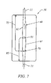
- FIG. 7 is a schematic representation showing the relationship of a single light source and photodetector used with the test chamber
- FIG. 8 is a schematic representation showing how two light sources are used on opposite ends of the test chamber
- FIG. 9 is a schematic representation on the line 9 — 9 of FIG. 8 showing the relationship of the two pairs of LEDs/photodetectors to the test chamber;
- FIG. 10 is an illustration of the top surface of layer 53 and the bottom surface of layer 52 shown in side-by-side relationship;
- FIG. 11 is an illustration of the bottom surface of layer 51 and the upper surface of layer 52 shown in side-by-side relation to illustrate the relationship of the LEDs to the test chamber;
- FIG. 12 is an illustration of the upper surface of layer 54 and the lower surface of layer 53 in side-by-side relationship to show the relationship of the two photodetectors relative to the test chamber.
- FIGS. 1 and 2 illustrate the overall environment of the invention.
- a hospitalized patient 9 typically in an ICU unit, is shown with a disposable testing unit 50 of the present invention attached to his forearm 8 by a Coban elastic band 7 .
- a catheter 45 is shown inserted into a patient blood vessel on the back of the patient's hand.
- a first infusion line 21 connects catheter 45 to testing unit 50 .
- a source of infusion fluid is shown as IV bag 20 suspended from a support 19 as is known in the art.
- Infusion fluid 25 stored in infusion bag 20 passes downwardly through a second infusion line 22 and through a reversible peristaltic pump 40 carried in monitor housing 30 .
- the second infusion line 22 continues downwardly from peristaltic pump 40 and enters the test unit 50 .
- the infusion fluid passes through testing unit 50 as described in detail below and through first infusion line 21 that extends from testing unit 50 to catheter 45 and provides infusion fluid into the patient's blood vessel.
- infusion fluid 21 from infusion source 20 is pumped through second infusion line 22 through testing unit 50 and through first infusion line 21 into the patient's blood vessel.
- the peristaltic pump is reversed and pumps infusion fluid and blood backwardly through test unit 50 until an undiluted blood sample is available for testing, as described in further detail below.
- test unit 50 Electrical power is fed to test unit 50 by line 100 extending from monitor 30 .
- a Luer fitting 110 is placed in infusion line 22 near test unit 50 .
- a syringe 120 is inserted into Luer fitting 110 for periodic calibration with a reference solution.
- FIG. 3 illustrates the monitor 30 having a screen 31 that displays the blood glucose level from the most recent test.
- the screen 31 also preferably displays blood pressure and pulse rate.
- An access door 35 located adjacent screen 31 opens to allow access to peristaltic pump 40 (shown in phantom) for placement of or removal of the disposable infusion line 22 .
- testing unit 50 in its preferred form includes a plurality of four plastic molded layers 51 – 54 .
- a test chamber 60 is formed between adjacent plastic layers 52 and 53 , which are transparent.
- a light source 70 is mounted between plastic layers 51 and 52 and adjacent test chamber 60 .
- Light source 70 is preferably a LED but may be other light sources known in the art.
- Light source 70 is energized by a flexible circuit 75 .
- a photodetector 80 is mounted between plastic layers 53 and 54 on the opposite side of test chamber 60 from light source 70 . Photodetector 80 is energized by flexible circuit 85 .
- a blood glucose tester 90 is carried by plastic layer 53 immediately adjacent testing chamber 60 .
- the blood glucose testing means 90 is preferably a glucose oxidase electrode 91 as known in the art. Electrode 91 is energized by flexible circuit 95 .
- the peristaltic pump 40 is reversed and infusion fluid combined with blood begins moving backwardly through first infusion line 21 through testing unit 50 and through testing chamber 60 .
- FIGS. 5 and 6 illustrate the four molded plastic layers 51 – 54 , from above in FIG. 5 and from below in FIG. 6 .
- the top layer 51 has an upper surface 51 a shown in FIG. 5 and a lower surface 51 b shown best in FIG. 6 .
- the lower surface 51 b carries light sources 70 and 170 . Light sources 70 and 170 are energized by flex circuits 75 and 175 , respectively.
- the top surface 52 a of layer 52 is flat as shown in FIG. 5 .
- Layer 52 is transparent.
- the lower surface 52 b of layer 52 has a channel 65 b formed therein.
- the central section of channel 65 b is shown as 60 b and forms the upper portion of test chamber 60 .
- the central portion 60 b of channel 65 b is a slightly widened segment of channel 65 b.
- the upper surface 53 a of layer 53 as shown in FIG. 5 carries a channel 65 a which cooperates with channel 65 b to form a passageway through which fluid flows through test unit shown generally as 50 .
- the central section 60 a of channel 65 a forms the lower half of test chamber 60 .
- the glucose oxidase electrode 91 is carried in channel 65 a and is positioned below and immediately adjacent to test chamber 60 formed by the central segments 60 a and 60 b of channel 65 a and 65 b , respectively.
- the glucose oxidase electrode 91 is energized by flex circuit 95 .
- the lower surface 53 b of layer 53 is flat as shown in FIG. 6 .
- the upper surface 54 a of layer 54 carries photodetectors 80 and 180 , energized by flex circuits 85 and 185 , respectively.
- the lower surface 54 b of layer 54 is shown in FIG. 6 .
- Surface 54 b has a gentle curvature to conform to the forearm of the patient.
- FIG. 7 which is a schematic representation looking downwardly at testing unit 50 (partially broken away)
- infusion fluid is shown flowing through first infusion line 21 and through testing chamber 60 and outwardly through second infusion line 22 .
- the peristaltic pump 40 continues to pump in the backward or reverse direction
- the patient's blood is drawn into first infusion line 21 and flows into and through testing chamber 60 .
- LED 70 is energized and the opacity of the fluid flowing past LED 70 is measured by the output of photodetector 80 (not visible in FIG. 7 ).
- the peristaltic pump is stopped, the glucose oxidase electrode 90 is energized and the blood glucose level is measured and immediately indicated on the screen 31 of monitor 30 , as shown best on FIGS. 2 and 3 .
- the peristaltic pump 40 is then energized to pump in the forward direction and the flow of infusion fluid into the patient's blood vessel is resumed.
- a single light source and photodetector pair are utilized. When a single pair is utilized, the pair is preferably placed adjacent the distal end 61 of test chamber 60 .
- a second light source 170 is placed adjacent the proximal end 62 of test chamber 60 .
- FIG. 8 The use of two pairs of LEDs and photodetectors as shown in FIG. 8 provides a more accurate determination of the presence of an undiluted sample of blood in test chamber 60 .
- the output of photodetectors 80 and 180 decreases.
- the peristaltic pump is stopped and the sample in test chamber 60 is tested.
- the output of photocells 80 and 180 is equal, it indicates that the sample flowing through test chamber 60 is equally opaque adjacent each photocell 80 and 180 . This indicates the presence of an undiluted blood sample in test chamber 60 .
- FIG. 9 is a schematic taken on the line 9 — 9 of FIG. 8 showing the flow of fluid into first infusion line 21 through test chamber 60 and outwardly through second infusion line 22 .
- the first LED 70 and photodetector 80 are shown adjacent the distal end 61 of chamber 60 .
- Second LED 170 and photodetector 180 are shown located adjacent proximal end 62 of test chamber 60 .
- the glucose oxidase electrode 90 is shown directly beneath and adjacent test chamber 60 .
- FIG. 10 illustrates the upper surface 53 a of layer 53 side-by-side with the lower surface 52 b of layer 52 .
- the channels 65 a and 65 b cooperate to form a single passageway through which infusion fluid and/or blood pass through testing unit 50 as described above.
- the central segment 60 a of channel 65 a and the central segment 60 b of channel 65 b cooperate to form test chamber 60 .
- Glucose oxidase electrode 90 is shown connected to flex circuit 95 .
- FIG. 10 best illustrates the shape of test chamber 60 , formed by channel segments 60 a and 60 b .
- the side walls of channels 65 a and 65 b are tapered only slightly in order to provide laminar flow across electrode 90 and to flush cells off the surface of electrode 90 between blood glucose testing sessions.
- FIG. 11 illustrates the bottom surface 51 b or layer 51 in side-by-side relationship with the top surface 52 a of layer 52 .
- Channel 65 b is shown in phantom, since it is formed in the lower surface of layer 52 and not visible in FIG. 11 .
- LEDs 70 and 170 are shown carried on the bottom surface 51 b of layer 51 and energized by flex circuits 75 and 175 .
- FIG. 12 illustrates the upper surface 54 a of layer 54 side-by-side with the lower surface 53 b of layer 53 .
- Channel 65 a is shown in phantom in FIG. 12 since it is formed on the upper surface 53 and is not visible in FIG. 12 .
- Photodetectors 80 and 180 are shown mounted on surface 54 a along with flex circuits 85 and 185 which energize them.
Abstract
Description
Claims (6)
Priority Applications (1)
| Application Number | Priority Date | Filing Date | Title |
|---|---|---|---|
| US11/228,827 US7162290B1 (en) | 2005-09-16 | 2005-09-16 | Method and apparatus for blood glucose testing from a reversible infusion line |
Applications Claiming Priority (1)
| Application Number | Priority Date | Filing Date | Title |
|---|---|---|---|
| US11/228,827 US7162290B1 (en) | 2005-09-16 | 2005-09-16 | Method and apparatus for blood glucose testing from a reversible infusion line |
Publications (1)
| Publication Number | Publication Date |
|---|---|
| US7162290B1 true US7162290B1 (en) | 2007-01-09 |
Family
ID=37633555
Family Applications (1)
| Application Number | Title | Priority Date | Filing Date |
|---|---|---|---|
| US11/228,827 Expired - Fee Related US7162290B1 (en) | 2005-09-16 | 2005-09-16 | Method and apparatus for blood glucose testing from a reversible infusion line |
Country Status (1)
| Country | Link |
|---|---|
| US (1) | US7162290B1 (en) |
Cited By (98)
| Publication number | Priority date | Publication date | Assignee | Title |
|---|---|---|---|---|
| US20060009727A1 (en) * | 2004-04-08 | 2006-01-12 | Chf Solutions Inc. | Method and apparatus for an extracorporeal control of blood glucose |
| US20060015024A1 (en) * | 2004-07-13 | 2006-01-19 | Mark Brister | Transcutaneous medical device with variable stiffness |
| US20060079809A1 (en) * | 2004-09-29 | 2006-04-13 | Daniel Goldberger | Blood monitoring system |
| US20060183985A1 (en) * | 2004-07-13 | 2006-08-17 | Mark Brister | Analyte sensor |
| US20060189926A1 (en) * | 2005-02-14 | 2006-08-24 | Hall W D | Apparatus and methods for analyzing body fluid samples |
| US20060195058A1 (en) * | 2005-02-14 | 2006-08-31 | Gable Jennifer H | Methods and apparatus for extracting and analyzing a bodily fluid |
| US20070179435A1 (en) * | 2005-12-21 | 2007-08-02 | Braig James R | Analyte detection system with periodic sample draw and body fluid analyzer |
| US20070179437A1 (en) * | 2006-02-02 | 2007-08-02 | Henry Grage | Method and apparatus for testing blood glucose in a reversible infusion line |
| US20070191716A1 (en) * | 2004-09-29 | 2007-08-16 | Daniel Goldberger | Blood monitoring system |
| US20070225675A1 (en) * | 2005-11-15 | 2007-09-27 | Mark Ries Robinson | Blood Analyte Determinations |
| US20080021294A1 (en) * | 2006-07-14 | 2008-01-24 | Levin Paul D | Disposable blood glucose sensor with internal pump |
| US20080200789A1 (en) * | 2006-10-04 | 2008-08-21 | Dexcom, Inc. | Analyte sensor |
| US20080197024A1 (en) * | 2003-12-05 | 2008-08-21 | Dexcom, Inc. | Analyte sensor |
| US20080200838A1 (en) * | 2005-11-28 | 2008-08-21 | Daniel Goldberger | Wearable, programmable automated blood testing system |
| US20080200788A1 (en) * | 2006-10-04 | 2008-08-21 | Dexcorn, Inc. | Analyte sensor |
| US20080200791A1 (en) * | 2006-10-04 | 2008-08-21 | Dexcom, Inc. | Analyte sensor |
| US20080262469A1 (en) * | 2004-02-26 | 2008-10-23 | Dexcom. Inc. | Integrated medicament delivery device for use with continuous analyte sensor |
| US20080275324A1 (en) * | 2006-05-23 | 2008-11-06 | Daniel Goldberger | Fluid Access Interface |
| US20090018424A1 (en) * | 2006-10-04 | 2009-01-15 | Dexcom, Inc. | Analyte sensor |
| US20090043171A1 (en) * | 2007-07-16 | 2009-02-12 | Peter Rule | Systems And Methods For Determining Physiological Parameters Using Measured Analyte Values |
| US20090048535A1 (en) * | 2007-08-13 | 2009-02-19 | Mark Ries Robinson | Detecting Cross-contamination in Blood Measurements with a Multilumen Catheter |
| US20090054754A1 (en) * | 2007-08-21 | 2009-02-26 | Mcmahon Dave | Clinician-controlled semi-automated medication management |
| US20090069743A1 (en) * | 2007-09-11 | 2009-03-12 | Baxter International Inc. | Infusion therapy sensor system |
| US20090088615A1 (en) * | 2007-10-01 | 2009-04-02 | Mark Ries Robinson | Indwelling Fiber Optic Probe for Blood Glucose Measurements |
| US20090124964A1 (en) * | 2003-12-05 | 2009-05-14 | Dexcom, Inc. | Integrated device for continuous in vivo analyte detection and simultaneous control of an infusion device |
| US20090131777A1 (en) * | 2006-10-04 | 2009-05-21 | Dexcom, Inc. | Analyte sensor |
| US20090131768A1 (en) * | 2006-10-04 | 2009-05-21 | Dexcom, Inc. | Analyte sensor |
| US20090131776A1 (en) * | 2006-10-04 | 2009-05-21 | Dexcom, Inc. | Analyte sensor |
| US20090131769A1 (en) * | 2006-10-04 | 2009-05-21 | Dexcom, Inc. | Analyte sensor |
| US20090137887A1 (en) * | 2006-10-04 | 2009-05-28 | Dexcom, Inc. | Analyte sensor |
| US20090143659A1 (en) * | 2003-08-01 | 2009-06-04 | Dexcom, Inc. | Analyte sensor |
| US20090157040A1 (en) * | 2007-12-17 | 2009-06-18 | Hospira, Inc. | Differential pressure based flow sensor assembly for medication delivery monitoring and method of using the same |
| US20090156975A1 (en) * | 2007-11-30 | 2009-06-18 | Mark Ries Robinson | Robust System and Methods for Blood Access |
| US20090178459A1 (en) * | 2003-08-01 | 2009-07-16 | Dexcom, Inc. | Analyte sensor |
| US20090182217A1 (en) * | 2003-12-05 | 2009-07-16 | Dexcom, Inc. | Analyte sensor |
| US20090240128A1 (en) * | 2008-02-21 | 2009-09-24 | Dexcom, Inc. | Systems and methods for blood glucose monitoring and alert delivery |
| US20090240121A1 (en) * | 2008-03-21 | 2009-09-24 | Nova Biomedical Corporation | Intravascular sensor and insertion set combination |
| EP2107885A1 (en) | 2007-01-26 | 2009-10-14 | Diramo A/S | Analysis system with a remote analysing unit |
| US20090264720A1 (en) * | 2008-04-17 | 2009-10-22 | The Cooper Health System | Wearable Automated Blood Sampling and Monitoring System |
| US20090281460A1 (en) * | 2008-05-08 | 2009-11-12 | Hospira, Inc. | Automated point-of-care fluid testing device and method of using the same |
| US20090287074A1 (en) * | 2006-10-04 | 2009-11-19 | Dexcom, Inc. | Analyte sensor |
| US20090288497A1 (en) * | 2008-05-23 | 2009-11-26 | Hospira, Inc. | Cassette for differential pressure based medication delivery flow sensor assembly for medication delivery monitoring and method of making the same |
| US20090299276A1 (en) * | 2004-02-26 | 2009-12-03 | Dexcom, Inc. | Integrated delivery device for continuous glucose sensor |
| US20090299156A1 (en) * | 2008-02-20 | 2009-12-03 | Dexcom, Inc. | Continuous medicament sensor system for in vivo use |
| US20100016698A1 (en) * | 2003-11-19 | 2010-01-21 | Dexcom, Inc. | Integrated receiver for continuous analyte sensor |
| US20100030038A1 (en) * | 2003-12-09 | 2010-02-04 | Dexcom. Inc. | Signal processing for continuous analyte sensor |
| US20100057058A1 (en) * | 2008-09-02 | 2010-03-04 | Hospira, Inc. | Cassette for use in a medication delivery flow sensor assembly and method of making the same |
| US20100094114A1 (en) * | 2008-10-09 | 2010-04-15 | Mark Ries Robinson | Use of multiple calibration solutions with an analyte sensor with use in an automated blood access system |
| US20100114027A1 (en) * | 2008-11-05 | 2010-05-06 | Hospira, Inc. | Fluid medication delivery systems for delivery monitoring of secondary medications |
| US20100168535A1 (en) * | 2006-04-12 | 2010-07-01 | Mark Ries Robinson | Methods and apparatuses related to blood analyte measurement system |
| US20100198155A1 (en) * | 2009-01-30 | 2010-08-05 | Hospira, Inc. | Cassette for differential pressure based medication delivery flow sensor assembly for medication delivery monitoring and method of making the same |
| US20100280486A1 (en) * | 2009-04-29 | 2010-11-04 | Hospira, Inc. | System and method for delivering and monitoring medication |
| US20100279418A1 (en) * | 2009-05-04 | 2010-11-04 | Loren Robert Larson | Glucose meter adaptable for use with handheld devices, and associated communication network |
| US20110009720A1 (en) * | 2006-11-02 | 2011-01-13 | Kislaya Kunjan | Continuous whole blood glucose monitor |
| US20110077480A1 (en) * | 2009-03-27 | 2011-03-31 | Intellidx, Inc. | Fluid transfer system and method |
| US20110152642A1 (en) * | 2009-12-18 | 2011-06-23 | Mak Ries Robinson | Detection of bubbles during hemodynamic monitoring when performing automated measurement of blood constituents |
| US20110184266A1 (en) * | 2010-01-25 | 2011-07-28 | Levin Paul D | Blood glucose monitoring system |
| US20110231107A1 (en) * | 2003-08-01 | 2011-09-22 | Dexcom, Inc. | Transcutaneous analyte sensor |
| US8348844B2 (en) | 2008-12-02 | 2013-01-08 | Kislaya Kunjan | Automated blood sampler and analyzer |
| US8396528B2 (en) | 2008-03-25 | 2013-03-12 | Dexcom, Inc. | Analyte sensor |
| US8447376B2 (en) | 2006-10-04 | 2013-05-21 | Dexcom, Inc. | Analyte sensor |
| US8562558B2 (en) | 2007-06-08 | 2013-10-22 | Dexcom, Inc. | Integrated medicament delivery device for use with continuous analyte sensor |
| US9091676B2 (en) | 2010-06-09 | 2015-07-28 | Optiscan Biomedical Corp. | Systems and methods for measuring multiple analytes in a sample |
| US9913604B2 (en) | 2005-02-14 | 2018-03-13 | Optiscan Biomedical Corporation | Analyte detection systems and methods using multiple measurements |
| US10022081B2 (en) | 2009-03-10 | 2018-07-17 | Trace Analytics, Gmbh | Sampling device and sampling method |
| US10022498B2 (en) | 2011-12-16 | 2018-07-17 | Icu Medical, Inc. | System for monitoring and delivering medication to a patient and method of using the same to minimize the risks associated with automated therapy |
| US10143795B2 (en) | 2014-08-18 | 2018-12-04 | Icu Medical, Inc. | Intravenous pole integrated power, control, and communication system and method for an infusion pump |
| US10166328B2 (en) | 2013-05-29 | 2019-01-01 | Icu Medical, Inc. | Infusion system which utilizes one or more sensors and additional information to make an air determination regarding the infusion system |
| US10342917B2 (en) | 2014-02-28 | 2019-07-09 | Icu Medical, Inc. | Infusion system and method which utilizes dual wavelength optical air-in-line detection |
| US10430761B2 (en) | 2011-08-19 | 2019-10-01 | Icu Medical, Inc. | Systems and methods for a graphical interface including a graphical representation of medical data |
| US10463788B2 (en) | 2012-07-31 | 2019-11-05 | Icu Medical, Inc. | Patient care system for critical medications |
| US10524703B2 (en) | 2004-07-13 | 2020-01-07 | Dexcom, Inc. | Transcutaneous analyte sensor |
| US10578474B2 (en) | 2012-03-30 | 2020-03-03 | Icu Medical, Inc. | Air detection system and method for detecting air in a pump of an infusion system |
| US10596316B2 (en) | 2013-05-29 | 2020-03-24 | Icu Medical, Inc. | Infusion system and method of use which prevents over-saturation of an analog-to-digital converter |
| US10610137B2 (en) | 2005-03-10 | 2020-04-07 | Dexcom, Inc. | System and methods for processing analyte sensor data for sensor calibration |
| US10635784B2 (en) | 2007-12-18 | 2020-04-28 | Icu Medical, Inc. | User interface improvements for medical devices |
| US10653835B2 (en) | 2007-10-09 | 2020-05-19 | Dexcom, Inc. | Integrated insulin delivery system with continuous glucose sensor |
| US10656894B2 (en) | 2017-12-27 | 2020-05-19 | Icu Medical, Inc. | Synchronized display of screen content on networked devices |
| US10813577B2 (en) | 2005-06-21 | 2020-10-27 | Dexcom, Inc. | Analyte sensor |
| US10850024B2 (en) | 2015-03-02 | 2020-12-01 | Icu Medical, Inc. | Infusion system, device, and method having advanced infusion features |
| US10874793B2 (en) | 2013-05-24 | 2020-12-29 | Icu Medical, Inc. | Multi-sensor infusion system for detecting air or an occlusion in the infusion system |
| US10918787B2 (en) | 2015-05-26 | 2021-02-16 | Icu Medical, Inc. | Disposable infusion fluid delivery device for programmable large volume drug delivery |
| US10980461B2 (en) | 2008-11-07 | 2021-04-20 | Dexcom, Inc. | Advanced analyte sensor calibration and error detection |
| US11000215B1 (en) | 2003-12-05 | 2021-05-11 | Dexcom, Inc. | Analyte sensor |
| US20210213197A1 (en) * | 2020-01-15 | 2021-07-15 | Comets Inc. | Infusion set |
| US11135360B1 (en) | 2020-12-07 | 2021-10-05 | Icu Medical, Inc. | Concurrent infusion with common line auto flush |
| USD939079S1 (en) | 2019-08-22 | 2021-12-21 | Icu Medical, Inc. | Infusion pump |
| US11213619B2 (en) | 2013-11-11 | 2022-01-04 | Icu Medical, Inc. | Thermal management system and method for medical devices |
| US11246985B2 (en) | 2016-05-13 | 2022-02-15 | Icu Medical, Inc. | Infusion pump system and method with common line auto flush |
| US11278671B2 (en) | 2019-12-04 | 2022-03-22 | Icu Medical, Inc. | Infusion pump with safety sequence keypad |
| US11324888B2 (en) | 2016-06-10 | 2022-05-10 | Icu Medical, Inc. | Acoustic flow sensor for continuous medication flow measurements and feedback control of infusion |
| US11331022B2 (en) | 2017-10-24 | 2022-05-17 | Dexcom, Inc. | Pre-connected analyte sensors |
| US11344673B2 (en) | 2014-05-29 | 2022-05-31 | Icu Medical, Inc. | Infusion system and pump with configurable closed loop delivery rate catch-up |
| US11344668B2 (en) | 2014-12-19 | 2022-05-31 | Icu Medical, Inc. | Infusion system with concurrent TPN/insulin infusion |
| US11350862B2 (en) | 2017-10-24 | 2022-06-07 | Dexcom, Inc. | Pre-connected analyte sensors |
| US11399745B2 (en) | 2006-10-04 | 2022-08-02 | Dexcom, Inc. | Dual electrode system for a continuous analyte sensor |
| US11633133B2 (en) | 2003-12-05 | 2023-04-25 | Dexcom, Inc. | Dual electrode system for a continuous analyte sensor |
| US11883361B2 (en) | 2020-07-21 | 2024-01-30 | Icu Medical, Inc. | Fluid transfer devices and methods of use |
Citations (9)
| Publication number | Priority date | Publication date | Assignee | Title |
|---|---|---|---|---|
| US3832067A (en) | 1972-11-24 | 1974-08-27 | Kopf D Syst | Colorimeter for detecting blood leaks in an artificial kidney machine |
| US3910256A (en) | 1972-12-29 | 1975-10-07 | Primary Childrens Hospital | Automated blood analysis system |
| US4573968A (en) | 1983-08-16 | 1986-03-04 | Ivac Corporation | Infusion and blood chemistry monitoring system |
| US5165406A (en) | 1990-09-13 | 1992-11-24 | Via Medical Corporation | Electrochemical sensor apparatus and method |
| US5206711A (en) * | 1990-06-11 | 1993-04-27 | The Babcock & Wilcox Company | Fluid opacity sensor |
| US5758643A (en) | 1996-07-29 | 1998-06-02 | Via Medical Corporation | Method and apparatus for monitoring blood chemistry |
| US5947911A (en) | 1997-01-09 | 1999-09-07 | Via Medical Corporation | Method and apparatus for reducing purge volume in a blood chemistry monitoring system |
| US20040015158A1 (en) | 2002-07-19 | 2004-01-22 | To-Mu Chen | Transilluminator device |
| US20040019280A1 (en) | 2001-02-12 | 2004-01-29 | Milton Waner | Infrared assisted monitoring of a catheter |
-
2005
- 2005-09-16 US US11/228,827 patent/US7162290B1/en not_active Expired - Fee Related
Patent Citations (9)
| Publication number | Priority date | Publication date | Assignee | Title |
|---|---|---|---|---|
| US3832067A (en) | 1972-11-24 | 1974-08-27 | Kopf D Syst | Colorimeter for detecting blood leaks in an artificial kidney machine |
| US3910256A (en) | 1972-12-29 | 1975-10-07 | Primary Childrens Hospital | Automated blood analysis system |
| US4573968A (en) | 1983-08-16 | 1986-03-04 | Ivac Corporation | Infusion and blood chemistry monitoring system |
| US5206711A (en) * | 1990-06-11 | 1993-04-27 | The Babcock & Wilcox Company | Fluid opacity sensor |
| US5165406A (en) | 1990-09-13 | 1992-11-24 | Via Medical Corporation | Electrochemical sensor apparatus and method |
| US5758643A (en) | 1996-07-29 | 1998-06-02 | Via Medical Corporation | Method and apparatus for monitoring blood chemistry |
| US5947911A (en) | 1997-01-09 | 1999-09-07 | Via Medical Corporation | Method and apparatus for reducing purge volume in a blood chemistry monitoring system |
| US20040019280A1 (en) | 2001-02-12 | 2004-01-29 | Milton Waner | Infrared assisted monitoring of a catheter |
| US20040015158A1 (en) | 2002-07-19 | 2004-01-22 | To-Mu Chen | Transilluminator device |
Cited By (229)
| Publication number | Priority date | Publication date | Assignee | Title |
|---|---|---|---|---|
| US8321149B2 (en) | 2003-08-01 | 2012-11-27 | Dexcom, Inc. | Transcutaneous analyte sensor |
| US8311749B2 (en) | 2003-08-01 | 2012-11-13 | Dexcom, Inc. | Transcutaneous analyte sensor |
| US20090143659A1 (en) * | 2003-08-01 | 2009-06-04 | Dexcom, Inc. | Analyte sensor |
| US10052055B2 (en) | 2003-08-01 | 2018-08-21 | Dexcom, Inc. | Analyte sensor |
| US8886273B2 (en) | 2003-08-01 | 2014-11-11 | Dexcom, Inc. | Analyte sensor |
| US8626257B2 (en) | 2003-08-01 | 2014-01-07 | Dexcom, Inc. | Analyte sensor |
| US8915849B2 (en) | 2003-08-01 | 2014-12-23 | Dexcom, Inc. | Transcutaneous analyte sensor |
| US20090178459A1 (en) * | 2003-08-01 | 2009-07-16 | Dexcom, Inc. | Analyte sensor |
| US20110231107A1 (en) * | 2003-08-01 | 2011-09-22 | Dexcom, Inc. | Transcutaneous analyte sensor |
| US20100179401A1 (en) * | 2003-11-19 | 2010-07-15 | Dexcom, Inc. | Integrated receiver for continuous analyte sensor |
| US9538946B2 (en) | 2003-11-19 | 2017-01-10 | Dexcom, Inc. | Integrated receiver for continuous analyte sensor |
| US20100016698A1 (en) * | 2003-11-19 | 2010-01-21 | Dexcom, Inc. | Integrated receiver for continuous analyte sensor |
| US11564602B2 (en) | 2003-11-19 | 2023-01-31 | Dexcom, Inc. | Integrated receiver for continuous analyte sensor |
| US20090182217A1 (en) * | 2003-12-05 | 2009-07-16 | Dexcom, Inc. | Analyte sensor |
| US11633133B2 (en) | 2003-12-05 | 2023-04-25 | Dexcom, Inc. | Dual electrode system for a continuous analyte sensor |
| US11000215B1 (en) | 2003-12-05 | 2021-05-11 | Dexcom, Inc. | Analyte sensor |
| US20080197024A1 (en) * | 2003-12-05 | 2008-08-21 | Dexcom, Inc. | Analyte sensor |
| US20090124964A1 (en) * | 2003-12-05 | 2009-05-14 | Dexcom, Inc. | Integrated device for continuous in vivo analyte detection and simultaneous control of an infusion device |
| US8425417B2 (en) | 2003-12-05 | 2013-04-23 | Dexcom, Inc. | Integrated device for continuous in vivo analyte detection and simultaneous control of an infusion device |
| US11020031B1 (en) | 2003-12-05 | 2021-06-01 | Dexcom, Inc. | Analyte sensor |
| US8287453B2 (en) | 2003-12-05 | 2012-10-16 | Dexcom, Inc. | Analyte sensor |
| US8265725B2 (en) | 2003-12-09 | 2012-09-11 | Dexcom, Inc. | Signal processing for continuous analyte sensor |
| US8233958B2 (en) | 2003-12-09 | 2012-07-31 | Dexcom, Inc. | Signal processing for continuous analyte sensor |
| US11638541B2 (en) | 2003-12-09 | 2023-05-02 | Dexconi, Inc. | Signal processing for continuous analyte sensor |
| US20100030038A1 (en) * | 2003-12-09 | 2010-02-04 | Dexcom. Inc. | Signal processing for continuous analyte sensor |
| US10898113B2 (en) | 2003-12-09 | 2021-01-26 | Dexcom, Inc. | Signal processing for continuous analyte sensor |
| US10278580B2 (en) | 2004-02-26 | 2019-05-07 | Dexcom, Inc. | Integrated medicament delivery device for use with continuous analyte sensor |
| US10835672B2 (en) | 2004-02-26 | 2020-11-17 | Dexcom, Inc. | Integrated insulin delivery system with continuous glucose sensor |
| US8926585B2 (en) | 2004-02-26 | 2015-01-06 | Dexcom, Inc. | Integrated delivery device for continuous glucose sensor |
| US9050413B2 (en) | 2004-02-26 | 2015-06-09 | Dexcom, Inc. | Integrated delivery device for continuous glucose sensor |
| US9155843B2 (en) | 2004-02-26 | 2015-10-13 | Dexcom, Inc. | Integrated delivery device for continuous glucose sensor |
| US9937293B2 (en) | 2004-02-26 | 2018-04-10 | Dexcom, Inc. | Integrated delivery device for continuous glucose sensor |
| US20080262469A1 (en) * | 2004-02-26 | 2008-10-23 | Dexcom. Inc. | Integrated medicament delivery device for use with continuous analyte sensor |
| US20090299276A1 (en) * | 2004-02-26 | 2009-12-03 | Dexcom, Inc. | Integrated delivery device for continuous glucose sensor |
| US8920401B2 (en) | 2004-02-26 | 2014-12-30 | Dexcom, Inc. | Integrated delivery device for continuous glucose sensor |
| US8460231B2 (en) | 2004-02-26 | 2013-06-11 | Dexcom, Inc. | Integrated delivery device for continuous glucose sensor |
| US8721585B2 (en) | 2004-02-26 | 2014-05-13 | Dex Com, Inc. | Integrated delivery device for continuous glucose sensor |
| US7976492B2 (en) | 2004-02-26 | 2011-07-12 | Dexcom, Inc. | Integrated delivery device for continuous glucose sensor |
| US8882741B2 (en) | 2004-02-26 | 2014-11-11 | Dexcom, Inc. | Integrated delivery device for continuous glucose sensor |
| US10966609B2 (en) | 2004-02-26 | 2021-04-06 | Dexcom, Inc. | Integrated medicament delivery device for use with continuous analyte sensor |
| US11246990B2 (en) | 2004-02-26 | 2022-02-15 | Dexcom, Inc. | Integrated delivery device for continuous glucose sensor |
| US8808228B2 (en) | 2004-02-26 | 2014-08-19 | Dexcom, Inc. | Integrated medicament delivery device for use with continuous analyte sensor |
| US20100114002A1 (en) * | 2004-04-08 | 2010-05-06 | O'mahony John J | Method and apparatus for an extracorporeal control of blood glucose |
| US20060009727A1 (en) * | 2004-04-08 | 2006-01-12 | Chf Solutions Inc. | Method and apparatus for an extracorporeal control of blood glucose |
| US10918314B2 (en) | 2004-07-13 | 2021-02-16 | Dexcom, Inc. | Analyte sensor |
| US7783333B2 (en) | 2004-07-13 | 2010-08-24 | Dexcom, Inc. | Transcutaneous medical device with variable stiffness |
| US11883164B2 (en) | 2004-07-13 | 2024-01-30 | Dexcom, Inc. | System and methods for processing analyte sensor data for sensor calibration |
| US20060015024A1 (en) * | 2004-07-13 | 2006-01-19 | Mark Brister | Transcutaneous medical device with variable stiffness |
| US10918315B2 (en) | 2004-07-13 | 2021-02-16 | Dexcom, Inc. | Analyte sensor |
| US20060183985A1 (en) * | 2004-07-13 | 2006-08-17 | Mark Brister | Analyte sensor |
| US7857760B2 (en) | 2004-07-13 | 2010-12-28 | Dexcom, Inc. | Analyte sensor |
| US11064917B2 (en) | 2004-07-13 | 2021-07-20 | Dexcom, Inc. | Analyte sensor |
| US10827956B2 (en) | 2004-07-13 | 2020-11-10 | Dexcom, Inc. | Analyte sensor |
| US11045120B2 (en) | 2004-07-13 | 2021-06-29 | Dexcom, Inc. | Analyte sensor |
| US11026605B1 (en) | 2004-07-13 | 2021-06-08 | Dexcom, Inc. | Analyte sensor |
| US10918313B2 (en) | 2004-07-13 | 2021-02-16 | Dexcom, Inc. | Analyte sensor |
| US10813576B2 (en) | 2004-07-13 | 2020-10-27 | Dexcom, Inc. | Analyte sensor |
| US10799159B2 (en) | 2004-07-13 | 2020-10-13 | Dexcom, Inc. | Analyte sensor |
| US10524703B2 (en) | 2004-07-13 | 2020-01-07 | Dexcom, Inc. | Transcutaneous analyte sensor |
| US10993642B2 (en) | 2004-07-13 | 2021-05-04 | Dexcom, Inc. | Analyte sensor |
| US10709363B2 (en) | 2004-07-13 | 2020-07-14 | Dexcom, Inc. | Analyte sensor |
| US10993641B2 (en) | 2004-07-13 | 2021-05-04 | Dexcom, Inc. | Analyte sensor |
| US10709362B2 (en) | 2004-07-13 | 2020-07-14 | Dexcom, Inc. | Analyte sensor |
| US10980452B2 (en) | 2004-07-13 | 2021-04-20 | Dexcom, Inc. | Analyte sensor |
| US10722152B2 (en) | 2004-07-13 | 2020-07-28 | Dexcom, Inc. | Analyte sensor |
| US10932700B2 (en) | 2004-07-13 | 2021-03-02 | Dexcom, Inc. | Analyte sensor |
| US10799158B2 (en) | 2004-07-13 | 2020-10-13 | Dexcom, Inc. | Analyte sensor |
| US20070191716A1 (en) * | 2004-09-29 | 2007-08-16 | Daniel Goldberger | Blood monitoring system |
| US20060079809A1 (en) * | 2004-09-29 | 2006-04-13 | Daniel Goldberger | Blood monitoring system |
| US20090156922A1 (en) * | 2005-02-01 | 2009-06-18 | Daniel Goldberger | Blood monitoring system |
| US20070060872A1 (en) * | 2005-02-14 | 2007-03-15 | Hall W D | Apparatus and methods for analyzing body fluid samples |
| US20100030137A1 (en) * | 2005-02-14 | 2010-02-04 | Optiscan Biomedical Corporation | Apparatus and methods for analyzing body fluid samples |
| US20060195058A1 (en) * | 2005-02-14 | 2006-08-31 | Gable Jennifer H | Methods and apparatus for extracting and analyzing a bodily fluid |
| US9913604B2 (en) | 2005-02-14 | 2018-03-13 | Optiscan Biomedical Corporation | Analyte detection systems and methods using multiple measurements |
| US20060189926A1 (en) * | 2005-02-14 | 2006-08-24 | Hall W D | Apparatus and methods for analyzing body fluid samples |
| US11000213B2 (en) | 2005-03-10 | 2021-05-11 | Dexcom, Inc. | System and methods for processing analyte sensor data for sensor calibration |
| US10925524B2 (en) | 2005-03-10 | 2021-02-23 | Dexcom, Inc. | System and methods for processing analyte sensor data for sensor calibration |
| US11051726B2 (en) | 2005-03-10 | 2021-07-06 | Dexcom, Inc. | System and methods for processing analyte sensor data for sensor calibration |
| US10856787B2 (en) | 2005-03-10 | 2020-12-08 | Dexcom, Inc. | System and methods for processing analyte sensor data for sensor calibration |
| US10898114B2 (en) | 2005-03-10 | 2021-01-26 | Dexcom, Inc. | System and methods for processing analyte sensor data for sensor calibration |
| US10918317B2 (en) | 2005-03-10 | 2021-02-16 | Dexcom, Inc. | System and methods for processing analyte sensor data for sensor calibration |
| US10610137B2 (en) | 2005-03-10 | 2020-04-07 | Dexcom, Inc. | System and methods for processing analyte sensor data for sensor calibration |
| US10610136B2 (en) | 2005-03-10 | 2020-04-07 | Dexcom, Inc. | System and methods for processing analyte sensor data for sensor calibration |
| US10918316B2 (en) | 2005-03-10 | 2021-02-16 | Dexcom, Inc. | System and methods for processing analyte sensor data for sensor calibration |
| US10918318B2 (en) | 2005-03-10 | 2021-02-16 | Dexcom, Inc. | System and methods for processing analyte sensor data for sensor calibration |
| US10617336B2 (en) | 2005-03-10 | 2020-04-14 | Dexcom, Inc. | System and methods for processing analyte sensor data for sensor calibration |
| US10743801B2 (en) | 2005-03-10 | 2020-08-18 | Dexcom, Inc. | System and methods for processing analyte sensor data for sensor calibration |
| US10610135B2 (en) | 2005-03-10 | 2020-04-07 | Dexcom, Inc. | System and methods for processing analyte sensor data for sensor calibration |
| US10716498B2 (en) | 2005-03-10 | 2020-07-21 | Dexcom, Inc. | System and methods for processing analyte sensor data for sensor calibration |
| US10709364B2 (en) | 2005-03-10 | 2020-07-14 | Dexcom, Inc. | System and methods for processing analyte sensor data for sensor calibration |
| US10813577B2 (en) | 2005-06-21 | 2020-10-27 | Dexcom, Inc. | Analyte sensor |
| US20070225675A1 (en) * | 2005-11-15 | 2007-09-27 | Mark Ries Robinson | Blood Analyte Determinations |
| US20090043240A1 (en) * | 2005-11-15 | 2009-02-12 | Mark Ries Robinson | Method and apparatus for blood transport using a pressure controller in measurement of blood characteristics |
| US20080200838A1 (en) * | 2005-11-28 | 2008-08-21 | Daniel Goldberger | Wearable, programmable automated blood testing system |
| US20090192367A1 (en) * | 2005-12-21 | 2009-07-30 | Optiscan Biomedical Corporation | Analyte detection system with periodic sample draw and body fluid analyzer |
| US20070179435A1 (en) * | 2005-12-21 | 2007-08-02 | Braig James R | Analyte detection system with periodic sample draw and body fluid analyzer |
| US20070179436A1 (en) * | 2005-12-21 | 2007-08-02 | Braig James R | Analyte detection system with periodic sample draw and laboratory-grade analyzer |
| US20070179437A1 (en) * | 2006-02-02 | 2007-08-02 | Henry Grage | Method and apparatus for testing blood glucose in a reversible infusion line |
| US7367942B2 (en) * | 2006-02-02 | 2008-05-06 | Palco Labs, Inc. | Method and apparatus for testing blood glucose in a reversible infusion line |
| US20100168535A1 (en) * | 2006-04-12 | 2010-07-01 | Mark Ries Robinson | Methods and apparatuses related to blood analyte measurement system |
| US8092385B2 (en) | 2006-05-23 | 2012-01-10 | Intellidx, Inc. | Fluid access interface |
| US20080275324A1 (en) * | 2006-05-23 | 2008-11-06 | Daniel Goldberger | Fluid Access Interface |
| US20080021294A1 (en) * | 2006-07-14 | 2008-01-24 | Levin Paul D | Disposable blood glucose sensor with internal pump |
| US20080097288A1 (en) * | 2006-07-14 | 2008-04-24 | Levin Paul D | Disposable blood glucose sensor with internal pump |
| US10349873B2 (en) | 2006-10-04 | 2019-07-16 | Dexcom, Inc. | Analyte sensor |
| US8447376B2 (en) | 2006-10-04 | 2013-05-21 | Dexcom, Inc. | Analyte sensor |
| US20090131768A1 (en) * | 2006-10-04 | 2009-05-21 | Dexcom, Inc. | Analyte sensor |
| US8298142B2 (en) | 2006-10-04 | 2012-10-30 | Dexcom, Inc. | Analyte sensor |
| US8364230B2 (en) | 2006-10-04 | 2013-01-29 | Dexcom, Inc. | Analyte sensor |
| US20090287074A1 (en) * | 2006-10-04 | 2009-11-19 | Dexcom, Inc. | Analyte sensor |
| US8364231B2 (en) | 2006-10-04 | 2013-01-29 | Dexcom, Inc. | Analyte sensor |
| US11382539B2 (en) | 2006-10-04 | 2022-07-12 | Dexcom, Inc. | Analyte sensor |
| US8774886B2 (en) | 2006-10-04 | 2014-07-08 | Dexcom, Inc. | Analyte sensor |
| US8532730B2 (en) | 2006-10-04 | 2013-09-10 | Dexcom, Inc. | Analyte sensor |
| US20090131776A1 (en) * | 2006-10-04 | 2009-05-21 | Dexcom, Inc. | Analyte sensor |
| US20090018424A1 (en) * | 2006-10-04 | 2009-01-15 | Dexcom, Inc. | Analyte sensor |
| US8911367B2 (en) | 2006-10-04 | 2014-12-16 | Dexcom, Inc. | Analyte sensor |
| US8275438B2 (en) | 2006-10-04 | 2012-09-25 | Dexcom, Inc. | Analyte sensor |
| US20080200791A1 (en) * | 2006-10-04 | 2008-08-21 | Dexcom, Inc. | Analyte sensor |
| US20080200788A1 (en) * | 2006-10-04 | 2008-08-21 | Dexcorn, Inc. | Analyte sensor |
| US7775975B2 (en) | 2006-10-04 | 2010-08-17 | Dexcom, Inc. | Analyte sensor |
| US8478377B2 (en) | 2006-10-04 | 2013-07-02 | Dexcom, Inc. | Analyte sensor |
| US11399745B2 (en) | 2006-10-04 | 2022-08-02 | Dexcom, Inc. | Dual electrode system for a continuous analyte sensor |
| US20090131769A1 (en) * | 2006-10-04 | 2009-05-21 | Dexcom, Inc. | Analyte sensor |
| US20080200789A1 (en) * | 2006-10-04 | 2008-08-21 | Dexcom, Inc. | Analyte sensor |
| US20090137887A1 (en) * | 2006-10-04 | 2009-05-28 | Dexcom, Inc. | Analyte sensor |
| US9451908B2 (en) | 2006-10-04 | 2016-09-27 | Dexcom, Inc. | Analyte sensor |
| US20100298684A1 (en) * | 2006-10-04 | 2010-11-25 | Dexcom, Inc. | Analyte sensor |
| US20100081910A1 (en) * | 2006-10-04 | 2010-04-01 | Dexcom, Inc. | Analyte sensor |
| US8449464B2 (en) | 2006-10-04 | 2013-05-28 | Dexcom, Inc. | Analyte sensor |
| US20090131777A1 (en) * | 2006-10-04 | 2009-05-21 | Dexcom, Inc. | Analyte sensor |
| US8562528B2 (en) | 2006-10-04 | 2013-10-22 | Dexcom, Inc. | Analyte sensor |
| US8425416B2 (en) | 2006-10-04 | 2013-04-23 | Dexcom, Inc. | Analyte sensor |
| US20110009720A1 (en) * | 2006-11-02 | 2011-01-13 | Kislaya Kunjan | Continuous whole blood glucose monitor |
| EP2107885A1 (en) | 2007-01-26 | 2009-10-14 | Diramo A/S | Analysis system with a remote analysing unit |
| US11373347B2 (en) | 2007-06-08 | 2022-06-28 | Dexcom, Inc. | Integrated medicament delivery device for use with continuous analyte sensor |
| US8562558B2 (en) | 2007-06-08 | 2013-10-22 | Dexcom, Inc. | Integrated medicament delivery device for use with continuous analyte sensor |
| US9741139B2 (en) | 2007-06-08 | 2017-08-22 | Dexcom, Inc. | Integrated medicament delivery device for use with continuous analyte sensor |
| US10403012B2 (en) | 2007-06-08 | 2019-09-03 | Dexcom, Inc. | Integrated medicament delivery device for use with continuous analyte sensor |
| US20090043171A1 (en) * | 2007-07-16 | 2009-02-12 | Peter Rule | Systems And Methods For Determining Physiological Parameters Using Measured Analyte Values |
| US8412293B2 (en) | 2007-07-16 | 2013-04-02 | Optiscan Biomedical Corporation | Systems and methods for determining physiological parameters using measured analyte values |
| US20090048535A1 (en) * | 2007-08-13 | 2009-02-19 | Mark Ries Robinson | Detecting Cross-contamination in Blood Measurements with a Multilumen Catheter |
| US20090054754A1 (en) * | 2007-08-21 | 2009-02-26 | Mcmahon Dave | Clinician-controlled semi-automated medication management |
| US20090069743A1 (en) * | 2007-09-11 | 2009-03-12 | Baxter International Inc. | Infusion therapy sensor system |
| WO2009036105A3 (en) * | 2007-09-11 | 2009-09-24 | Baxter International Inc | Infusion therapy sensor system |
| US20090088615A1 (en) * | 2007-10-01 | 2009-04-02 | Mark Ries Robinson | Indwelling Fiber Optic Probe for Blood Glucose Measurements |
| US10653835B2 (en) | 2007-10-09 | 2020-05-19 | Dexcom, Inc. | Integrated insulin delivery system with continuous glucose sensor |
| US11744943B2 (en) | 2007-10-09 | 2023-09-05 | Dexcom, Inc. | Integrated insulin delivery system with continuous glucose sensor |
| US11160926B1 (en) | 2007-10-09 | 2021-11-02 | Dexcom, Inc. | Pre-connected analyte sensors |
| US20090156975A1 (en) * | 2007-11-30 | 2009-06-18 | Mark Ries Robinson | Robust System and Methods for Blood Access |
| US8403908B2 (en) | 2007-12-17 | 2013-03-26 | Hospira, Inc. | Differential pressure based flow sensor assembly for medication delivery monitoring and method of using the same |
| US9272089B2 (en) | 2007-12-17 | 2016-03-01 | Hospira, Inc. | Differential pressure based flow sensor assembly for medication delivery monitoring and method of using the same |
| US20090157040A1 (en) * | 2007-12-17 | 2009-06-18 | Hospira, Inc. | Differential pressure based flow sensor assembly for medication delivery monitoring and method of using the same |
| US10635784B2 (en) | 2007-12-18 | 2020-04-28 | Icu Medical, Inc. | User interface improvements for medical devices |
| US20090299156A1 (en) * | 2008-02-20 | 2009-12-03 | Dexcom, Inc. | Continuous medicament sensor system for in vivo use |
| US20090240120A1 (en) * | 2008-02-21 | 2009-09-24 | Dexcom, Inc. | Systems and methods for processing, transmitting and displaying sensor data |
| US11102306B2 (en) | 2008-02-21 | 2021-08-24 | Dexcom, Inc. | Systems and methods for processing, transmitting and displaying sensor data |
| US20090240193A1 (en) * | 2008-02-21 | 2009-09-24 | Dexcom, Inc. | Systems and methods for customizing delivery of sensor data |
| US8591455B2 (en) | 2008-02-21 | 2013-11-26 | Dexcom, Inc. | Systems and methods for customizing delivery of sensor data |
| US9020572B2 (en) | 2008-02-21 | 2015-04-28 | Dexcom, Inc. | Systems and methods for processing, transmitting and displaying sensor data |
| US20090240128A1 (en) * | 2008-02-21 | 2009-09-24 | Dexcom, Inc. | Systems and methods for blood glucose monitoring and alert delivery |
| US9143569B2 (en) | 2008-02-21 | 2015-09-22 | Dexcom, Inc. | Systems and methods for processing, transmitting and displaying sensor data |
| US8229535B2 (en) | 2008-02-21 | 2012-07-24 | Dexcom, Inc. | Systems and methods for blood glucose monitoring and alert delivery |
| US20090240121A1 (en) * | 2008-03-21 | 2009-09-24 | Nova Biomedical Corporation | Intravascular sensor and insertion set combination |
| US11896374B2 (en) | 2008-03-25 | 2024-02-13 | Dexcom, Inc. | Analyte sensor |
| US10602968B2 (en) | 2008-03-25 | 2020-03-31 | Dexcom, Inc. | Analyte sensor |
| US8396528B2 (en) | 2008-03-25 | 2013-03-12 | Dexcom, Inc. | Analyte sensor |
| US20090264720A1 (en) * | 2008-04-17 | 2009-10-22 | The Cooper Health System | Wearable Automated Blood Sampling and Monitoring System |
| US20090281460A1 (en) * | 2008-05-08 | 2009-11-12 | Hospira, Inc. | Automated point-of-care fluid testing device and method of using the same |
| US8523797B2 (en) | 2008-05-08 | 2013-09-03 | Hospira, Inc. | Automated point-of-care fluid testing device and method of using the same |
| US8065924B2 (en) | 2008-05-23 | 2011-11-29 | Hospira, Inc. | Cassette for differential pressure based medication delivery flow sensor assembly for medication delivery monitoring and method of making the same |
| US20090288497A1 (en) * | 2008-05-23 | 2009-11-26 | Hospira, Inc. | Cassette for differential pressure based medication delivery flow sensor assembly for medication delivery monitoring and method of making the same |
| US7819838B2 (en) | 2008-09-02 | 2010-10-26 | Hospira, Inc. | Cassette for use in a medication delivery flow sensor assembly and method of making the same |
| US20100057058A1 (en) * | 2008-09-02 | 2010-03-04 | Hospira, Inc. | Cassette for use in a medication delivery flow sensor assembly and method of making the same |
| US8657778B2 (en) | 2008-09-02 | 2014-02-25 | Hospira, Inc. | Cassette for use in a medication delivery flow sensor assembly and method of making the same |
| US20100286599A1 (en) * | 2008-09-02 | 2010-11-11 | Ziegler John S | Cassette for use in a medication delivery flow sensor assembly and method of making the same |
| US20100094114A1 (en) * | 2008-10-09 | 2010-04-15 | Mark Ries Robinson | Use of multiple calibration solutions with an analyte sensor with use in an automated blood access system |
| US20100114027A1 (en) * | 2008-11-05 | 2010-05-06 | Hospira, Inc. | Fluid medication delivery systems for delivery monitoring of secondary medications |
| US10980461B2 (en) | 2008-11-07 | 2021-04-20 | Dexcom, Inc. | Advanced analyte sensor calibration and error detection |
| US8348844B2 (en) | 2008-12-02 | 2013-01-08 | Kislaya Kunjan | Automated blood sampler and analyzer |
| US20100198155A1 (en) * | 2009-01-30 | 2010-08-05 | Hospira, Inc. | Cassette for differential pressure based medication delivery flow sensor assembly for medication delivery monitoring and method of making the same |
| US8048022B2 (en) | 2009-01-30 | 2011-11-01 | Hospira, Inc. | Cassette for differential pressure based medication delivery flow sensor assembly for medication delivery monitoring and method of making the same |
| US10022081B2 (en) | 2009-03-10 | 2018-07-17 | Trace Analytics, Gmbh | Sampling device and sampling method |
| US8753290B2 (en) | 2009-03-27 | 2014-06-17 | Intellectual Inspiration, Llc | Fluid transfer system and method |
| US20110077480A1 (en) * | 2009-03-27 | 2011-03-31 | Intellidx, Inc. | Fluid transfer system and method |
| US20100280486A1 (en) * | 2009-04-29 | 2010-11-04 | Hospira, Inc. | System and method for delivering and monitoring medication |
| US20100279418A1 (en) * | 2009-05-04 | 2010-11-04 | Loren Robert Larson | Glucose meter adaptable for use with handheld devices, and associated communication network |
| US8323194B2 (en) | 2009-12-18 | 2012-12-04 | Inlight Solutions, Inc. | Detection of bubbles during hemodynamic monitoring when performing automated measurement of blood constituents |
| US20110152642A1 (en) * | 2009-12-18 | 2011-06-23 | Mak Ries Robinson | Detection of bubbles during hemodynamic monitoring when performing automated measurement of blood constituents |
| US20110184266A1 (en) * | 2010-01-25 | 2011-07-28 | Levin Paul D | Blood glucose monitoring system |
| US9091676B2 (en) | 2010-06-09 | 2015-07-28 | Optiscan Biomedical Corp. | Systems and methods for measuring multiple analytes in a sample |
| US11004035B2 (en) | 2011-08-19 | 2021-05-11 | Icu Medical, Inc. | Systems and methods for a graphical interface including a graphical representation of medical data |
| US11599854B2 (en) | 2011-08-19 | 2023-03-07 | Icu Medical, Inc. | Systems and methods for a graphical interface including a graphical representation of medical data |
| US10430761B2 (en) | 2011-08-19 | 2019-10-01 | Icu Medical, Inc. | Systems and methods for a graphical interface including a graphical representation of medical data |
| US11376361B2 (en) | 2011-12-16 | 2022-07-05 | Icu Medical, Inc. | System for monitoring and delivering medication to a patient and method of using the same to minimize the risks associated with automated therapy |
| US10022498B2 (en) | 2011-12-16 | 2018-07-17 | Icu Medical, Inc. | System for monitoring and delivering medication to a patient and method of using the same to minimize the risks associated with automated therapy |
| US11933650B2 (en) | 2012-03-30 | 2024-03-19 | Icu Medical, Inc. | Air detection system and method for detecting air in a pump of an infusion system |
| US10578474B2 (en) | 2012-03-30 | 2020-03-03 | Icu Medical, Inc. | Air detection system and method for detecting air in a pump of an infusion system |
| US11623042B2 (en) | 2012-07-31 | 2023-04-11 | Icu Medical, Inc. | Patient care system for critical medications |
| US10463788B2 (en) | 2012-07-31 | 2019-11-05 | Icu Medical, Inc. | Patient care system for critical medications |
| US10874793B2 (en) | 2013-05-24 | 2020-12-29 | Icu Medical, Inc. | Multi-sensor infusion system for detecting air or an occlusion in the infusion system |
| US10166328B2 (en) | 2013-05-29 | 2019-01-01 | Icu Medical, Inc. | Infusion system which utilizes one or more sensors and additional information to make an air determination regarding the infusion system |
| US11596737B2 (en) | 2013-05-29 | 2023-03-07 | Icu Medical, Inc. | Infusion system and method of use which prevents over-saturation of an analog-to-digital converter |
| US10596316B2 (en) | 2013-05-29 | 2020-03-24 | Icu Medical, Inc. | Infusion system and method of use which prevents over-saturation of an analog-to-digital converter |
| US11433177B2 (en) | 2013-05-29 | 2022-09-06 | Icu Medical, Inc. | Infusion system which utilizes one or more sensors and additional information to make an air determination regarding the infusion system |
| US11213619B2 (en) | 2013-11-11 | 2022-01-04 | Icu Medical, Inc. | Thermal management system and method for medical devices |
| US10342917B2 (en) | 2014-02-28 | 2019-07-09 | Icu Medical, Inc. | Infusion system and method which utilizes dual wavelength optical air-in-line detection |
| US11344673B2 (en) | 2014-05-29 | 2022-05-31 | Icu Medical, Inc. | Infusion system and pump with configurable closed loop delivery rate catch-up |
| US10143795B2 (en) | 2014-08-18 | 2018-12-04 | Icu Medical, Inc. | Intravenous pole integrated power, control, and communication system and method for an infusion pump |
| US11344668B2 (en) | 2014-12-19 | 2022-05-31 | Icu Medical, Inc. | Infusion system with concurrent TPN/insulin infusion |
| US10850024B2 (en) | 2015-03-02 | 2020-12-01 | Icu Medical, Inc. | Infusion system, device, and method having advanced infusion features |
| US11660386B2 (en) | 2015-05-26 | 2023-05-30 | Icu Medical, Inc. | Disposable infusion fluid delivery device for programmable large volume drug delivery |
| US10918787B2 (en) | 2015-05-26 | 2021-02-16 | Icu Medical, Inc. | Disposable infusion fluid delivery device for programmable large volume drug delivery |
| US11246985B2 (en) | 2016-05-13 | 2022-02-15 | Icu Medical, Inc. | Infusion pump system and method with common line auto flush |
| US11324888B2 (en) | 2016-06-10 | 2022-05-10 | Icu Medical, Inc. | Acoustic flow sensor for continuous medication flow measurements and feedback control of infusion |
| US11706876B2 (en) | 2017-10-24 | 2023-07-18 | Dexcom, Inc. | Pre-connected analyte sensors |
| US11943876B2 (en) | 2017-10-24 | 2024-03-26 | Dexcom, Inc. | Pre-connected analyte sensors |
| US11331022B2 (en) | 2017-10-24 | 2022-05-17 | Dexcom, Inc. | Pre-connected analyte sensors |
| US11350862B2 (en) | 2017-10-24 | 2022-06-07 | Dexcom, Inc. | Pre-connected analyte sensors |
| US11382540B2 (en) | 2017-10-24 | 2022-07-12 | Dexcom, Inc. | Pre-connected analyte sensors |
| US11868161B2 (en) | 2017-12-27 | 2024-01-09 | Icu Medical, Inc. | Synchronized display of screen content on networked devices |
| US10656894B2 (en) | 2017-12-27 | 2020-05-19 | Icu Medical, Inc. | Synchronized display of screen content on networked devices |
| US11029911B2 (en) | 2017-12-27 | 2021-06-08 | Icu Medical, Inc. | Synchronized display of screen content on networked devices |
| USD939079S1 (en) | 2019-08-22 | 2021-12-21 | Icu Medical, Inc. | Infusion pump |
| US11278671B2 (en) | 2019-12-04 | 2022-03-22 | Icu Medical, Inc. | Infusion pump with safety sequence keypad |
| US11701466B2 (en) * | 2020-01-15 | 2023-07-18 | Comets Inc. | Infusion set |
| US20210213197A1 (en) * | 2020-01-15 | 2021-07-15 | Comets Inc. | Infusion set |
| US11883361B2 (en) | 2020-07-21 | 2024-01-30 | Icu Medical, Inc. | Fluid transfer devices and methods of use |
| US11135360B1 (en) | 2020-12-07 | 2021-10-05 | Icu Medical, Inc. | Concurrent infusion with common line auto flush |
Similar Documents
| Publication | Publication Date | Title |
|---|---|---|
| US7162290B1 (en) | Method and apparatus for blood glucose testing from a reversible infusion line | |
| US7367942B2 (en) | Method and apparatus for testing blood glucose in a reversible infusion line | |
| US4573968A (en) | Infusion and blood chemistry monitoring system | |
| US10660557B2 (en) | Fluid analysis cuvette with coupled transparent windows | |
| US8317698B2 (en) | Method of monitoring an automated point-of-care fluid testing system | |
| US7608042B2 (en) | Blood monitoring system | |
| US5193545A (en) | Device for determining at least one medical variable | |
| US8523797B2 (en) | Automated point-of-care fluid testing device and method of using the same | |
| JP3220154B2 (en) | Calibration solution for analysis of biological fluid and method of using the same | |
| CA2476650C (en) | Multilumen catheter | |
| US5947911A (en) | Method and apparatus for reducing purge volume in a blood chemistry monitoring system | |
| US20060229531A1 (en) | Blood monitoring system | |
| US20090156922A1 (en) | Blood monitoring system | |
| Sekiguchi et al. | Gastric PCO2 monitoring system based on a double membrane type PCO2 sensor | |
| Karvannan et al. | Non-Invasive Patient Health and Insulin Level Monitoring System | |
| CN112642018A (en) | Blood glucose detection device matched with venous indwelling needle and detection method thereof | |
| CN112716489A (en) | Venous blood glucose detection device and detection method thereof | |
| Dech | Blood conservation in the critically ill | |
| Shanahan et al. | The effect of patient backrest on the measurement of cardiac output | |
| Mardegan | The reliability of blood glucose measurements from radial arterial lines |
Legal Events
| Date | Code | Title | Description |
|---|---|---|---|
| AS | Assignment |
Owner name: SAN JOSE NATIONAL BANK, CALIFORNIA Free format text: SECURITY INTEREST;ASSIGNORS:PALCO LABS, INC.;LEVIN, PAUL D.;REEL/FRAME:017215/0370 Effective date: 20060119 |
|
| AS | Assignment |
Owner name: PALCO LABS, INC., CALIFORNIA Free format text: ASSIGNMENT OF ASSIGNORS INTEREST;ASSIGNOR:LEVIN, PAUL D.;REEL/FRAME:018263/0351 Effective date: 20050915 |
|
| REMI | Maintenance fee reminder mailed | ||
| LAPS | Lapse for failure to pay maintenance fees | ||
| STCH | Information on status: patent discontinuation |
Free format text: PATENT EXPIRED DUE TO NONPAYMENT OF MAINTENANCE FEES UNDER 37 CFR 1.362 |
|
| FP | Expired due to failure to pay maintenance fee |
Effective date: 20110109 |