US7177350B1 - Receiver transparent quiescent mode operation in a DSL transmission system - Google Patents
Receiver transparent quiescent mode operation in a DSL transmission system Download PDFInfo
- Publication number
- US7177350B1 US7177350B1 US10/118,859 US11885902A US7177350B1 US 7177350 B1 US7177350 B1 US 7177350B1 US 11885902 A US11885902 A US 11885902A US 7177350 B1 US7177350 B1 US 7177350B1
- Authority
- US
- United States
- Prior art keywords
- peak
- average ratio
- signal
- time
- subset
- Prior art date
- Legal status (The legal status is an assumption and is not a legal conclusion. Google has not performed a legal analysis and makes no representation as to the accuracy of the status listed.)
- Expired - Fee Related, expires
Links
Images


Classifications
-
- H—ELECTRICITY
- H04—ELECTRIC COMMUNICATION TECHNIQUE
- H04L—TRANSMISSION OF DIGITAL INFORMATION, e.g. TELEGRAPHIC COMMUNICATION
- H04L27/00—Modulated-carrier systems
- H04L27/26—Systems using multi-frequency codes
- H04L27/2601—Multicarrier modulation systems
- H04L27/2614—Peak power aspects
-
- H—ELECTRICITY
- H04—ELECTRIC COMMUNICATION TECHNIQUE
- H04L—TRANSMISSION OF DIGITAL INFORMATION, e.g. TELEGRAPHIC COMMUNICATION
- H04L27/00—Modulated-carrier systems
- H04L27/32—Carrier systems characterised by combinations of two or more of the types covered by groups H04L27/02, H04L27/10, H04L27/18 or H04L27/26
- H04L27/34—Amplitude- and phase-modulated carrier systems, e.g. quadrature-amplitude modulated carrier systems
- H04L27/3405—Modifications of the signal space to increase the efficiency of transmission, e.g. reduction of the bit error rate, bandwidth, or average power
- H04L27/3411—Modifications of the signal space to increase the efficiency of transmission, e.g. reduction of the bit error rate, bandwidth, or average power reducing the peak to average power ratio or the mean power of the constellation; Arrangements for increasing the shape gain of a signal set
Definitions
- the present invention relates to a power saving mode such as a quiescent mode (Q-mode) in Digital Subscriber Line (DSL) modems.
- a quiescent mode such as a quiescent mode (Q-mode) in Digital Subscriber Line (DSL) modems.
- DSL Digital Subscriber Line
- Digital Subscriber Line (DSL) systems are high-bandwidth technologies that use the existing copper-cable telephone lines.
- DSL can provide bandwidth up to 8 Mbps downstream, or up to 2 Mbps for symmetric transmission.
- DSL technology includes High bit-rate Digital Subscriber Line (HDSL), Asymmetric Digital Subscriber Line (ADSL) and Very high speed Digital Subscriber Line (VDSL).
- ADSL is particularly attractive for consumer Internet applications where most of the data traffic is downloaded to the customer. Upstream bandwidth for uploading data can be reduced to increase downstream bandwidth since most Internet traffic is downstream traffic.
- DSL Quadrature Amplitude Modulation
- DMT Discrete Multitone
- DSL digital subscriber line
- ADSL symmetric digital subscriber line
- VDSL very high speed digital subscriber line
- a channel comprises sub-channels, also referred to as frequency bins, bins, or carriers.
- Each sub-channel has sine and cosine frequencies that are integer multiples of a common frequency, the inverse of this common frequency being the symbol period.
- the sub-channels use integer multiples of the reciprocal of the common frequency.
- the waves are sent over the sub-channel simultaneously, and the amplitude and phase of each wave represents a group of information bits.
- the sine and cosine frequencies in any sub-channel are orthogonal to those in any other sub-channel to ensure that interference does not exist between the sub-channels.
- Each sub-channel is encoded to a constellation having points wherein each point is unique for each combination of bits. For example, a sub-channel carrying a 2-bit symbol would be encoded using a 4-point constellation, and a 3 bit symbol in another sub-channel would be encoded for an 8-point constellation.
- each receiver is tuned to all the sub-channels at once. Throughout transmission, a modem's receiver will be decoding the sub-channels.
- the DSL modems have several stages of initialization and training in which the transmitter and receiver decide on operating parameters, for example options, filter values, the distribution of bits among the bins and fine gain adjustments of the bins, that will be in effect for a steady-state operation mode in which payload data is transmitted.
- An embodiment of this payload carrying state is SHOWTIME in the ADSL context.
- Payload data comprises user data such as a requested web page as opposed to filler or idle signals that are used to keep the transmitter and receiver synchronized.
- Such a state of no communication of payload data extending for a period of time provides an opportunity to be able to save power during this period of time.
- a state or mode of power saving triggered by no transmission of payload data for a defined time period is referred to hereafter as a quiescent mode or Q-mode.
- the benefits of a power saving quiescent mode are increased density, reduced cooling, reduced battery backup capacity and therefore reduced cost that are obtained by reducing the busy hour power consumption.
- the receiver side such as may be located at a customer's premises equipment (CPE) substantial savings in idle power avoids the need to power the modem down when the remote is not in use, due to industry idle power requirements.
- CPE customer's premises equipment
- shut off the transmitter when there is no data to send.
- This approach is associated with a number of issues. For example, shutting off the transmitter causes non-stationary crosstalk in the associated loop binder.
- the upper layers of the communication system e.g., backbone of the communication network such as Asynchronous Transfer Mode (ATM)
- ATM Asynchronous Transfer Mode
- the receiver will lose synchronization and therefore need to train up when the idle period ends (e.g., user data resumes).
- PAR peak-to-average ratio
- the peak-to-average ratio (PAR) is the ratio of the peak voltage to the root-mean-square RMS voltage of the transmitted time-domain signal.
- the average power of the transmitted signal is related to the root-mean-square (RMS) average of the signal.
- FIG. 1A shows a frequency spectrum of a discrete-multi-tone DSL signal.
- the transmitted signal is composed of several separate carriers that are sufficiently separated in frequency so that the data from separate carriers can be extracted.
- the carriers are separated into frequency bins 0 , 1 , 2 , 3 , . . . N ⁇ 1.
- the N carriers in N frequency bins are combined by the transmitter into a single output signal that contains information from all N carrier waves.
- FIG. 1B shows a multi-carrier time-domain signal converted from the frequency-domain representation of FIG. 1A by an inverse fast-Fourier transform of the N carrier bins.
- Some of the samples of the time-domain signal are below the RMS voltage while other samples are above the RMS voltage.
- Peak voltages e.g. peak voltage 20
- Peak threshold such as may be associated with the dynamic range of a digital-to-analog converter or an amplifier such as a line driver. More expensive and power-consuming DACs and line drivers with a wider dynamic range may be needed.
- the PAR depends on several factors, such as the line code used for symbol encoding, the number of carriers, and the number of signal levels used to encode the symbols.
- Filtering also affects the PAR, as does the channel (e.g. telephone line) and echo path for the received signal. Reducing the peak of the Q-mode signal while keeping the average power the same helps reduce the power consumption in the modem line driver.
- the modem line driver typically consumes a significant portion of the total power consumed in normal operation of the ADSL modem.
- Known Q-mode techniques utilize a Q-mode “filler” symbol with low PAR properties in order to save power at the transmitter.
- a filler symbol may be defined in the transmitter and communicated to the receiver during initialization.
- Such proposals use REVERB or a similar 4-QAM signal as the filler, due to such signals having small PAR.
- the REVERB power spectral density (PSD) may not be similar to SHOWTIME PSD. In REVERB, all the bins are transmitted, while in SHOWTIME, some bins may not be transmitted. For example, on long loops, many high bins are not used.
- the PSD in SHOWTIME is gain (g i ) scaled, while in REVERB, the gain is flat.
- the most desirable features for Q-mode operation are the stationary aspect of the crosstalk, transparency to the receiver during SHOWTIME, and the ability to optimize the PAR characteristic of the Q-mode signal. None of the known techniques provide all these features. For example, while one technique may be transparent to the receiver during SHOWTIME, it fails to provide flexibility to improve the PAR characteristics of the Q-mode signal. Similarly, while another technique provides flexibility to improve the PAR characteristics of the Q-mode signal, it is not transparent to the receiver during SHOWTIME.
- the present invention overcomes or alleviates the disadvantages of the prior art by providing a system and method for generating a Q-mode signal having an optimized PAR characteristic and one of the QAM points Q i from a QAM constellation at each bin used during a payload carrying state of a DSL system.
- An example of such a state is SHOWTIME in ADSL transmission systems.
- a Q-mode signal is used for transmission between a transmitter and a receiver during a power saving or quiescent mode which is entered into from the steady-state or normal operation mode when criteria indicates that the transmitter has stopped transmitting payload data for a certain time period but that the current transmission session has not ended.
- the present invention provides for the selection of at least one of the QAM points, Q i from the SHOWTIME constellation at each used bin. Additionally, the gain (g i ) scale at each bin used during SHOWTIME is maintained during Q-mode, so that the Q-mode power spectral density (PSD) is very close to the SHOWTIME PSD. By keeping the same g i ripple, the stationary aspect of the crosstalk is maintained. Because the signal used in Q-mode is one of the SHOWTIME signal points, the receiver operates transparently. In other words, the receiver will continue to operate the same whether in SHOWTIME or Q-mode.
- a system for minimizing the PAR of the Q-mode signal comprises a processing unit for performing a PAR minimization method, a bit-to-symbol encoder, an inverse fast-Fourier transformer for transforming symbols, Q i 's, into a time-domain signal, and a power detector for detecting the average power and peaks outside the peak threshold.
- a processing unit for performing a PAR minimization method for performing a PAR minimization method, a bit-to-symbol encoder, an inverse fast-Fourier transformer for transforming symbols, Q i 's, into a time-domain signal, and a power detector for detecting the average power and peaks outside the peak threshold.
- a power detector for detecting the average power and peaks outside the peak threshold.
- One or more of the elements of the system may be embodied in hardware, firmware, software or any combination of these.
- An example of one embodiment is a digital signal processor.
- this system may be used to implement an embodiment of a method for minimizing the PAR of the Q-mode signal.
- the method comprises selecting a candidate set of constellation points used during the payload data carrying mode, ⁇ Q i ⁇ , for each bin used during the payload data carrying mode, storing the candidate sets, and determining the optimum combination of points from all the candidate sets for a minimum PAR of the Q-mode signal to be transmitted.
- the set of binary input bits ⁇ X i ⁇ corresponding to the optimum combination of Q i candidates is determined, stored in memory for use by the transmitter, and communicated to the receiver for storage in its memory.
- a computer usable medium may also comprise instructions which when executed cause a processor to perform the method.
- the present invention provides a transmitter for use in a DSL system, the transmitter comprising a memory having a table for storing the set of binary input bits ⁇ X i ⁇ corresponding to the optimum combination for minimizing PAR of Q i candidates, a mapping module for mapping the set of bits ⁇ X i ⁇ to an input data stream to be transmitted during Q-mode, a QAM encoder for encoding an X i to its corresponding constellation point Q i in the combination, and an inverse Fast Fourier Transformer for generating a time domain signal representing the combination of Q i points.
- the present invention provides an embodiment of a Q-mode signal comprising a combination of Q i points representing a time domain signal having a PAR within a threshold, each Q i point having an average power within a threshold of an average power of a point for the same bin of a low PAR signal that has a highly stationary crosstalk characteristic.
- FIG. 1A shows a frequency spectrum of a discrete-multi-tone DSL signal.
- FIG. 1B shows a multi-carrier time-domain signal converted from the frequency-domain representation of FIG. 1A by an inverse fast-Fourier transform of the N carrier bins.
- FIG. 2 illustrates an example of a constellation map of a 4-QAM low PAR signal having a stationary crosstalk characteristic for a bin, and an example a 16-QAM SHOWTIME constellation for the same bin in accordance with an embodiment of the present invention.
- FIG. 4 illustrates an ADSL transmission system having a transmitter and a receiver in accordance with an embodiment of the present invention.
- FIG. 5 illustrates a random quadrant selection PAR minimization algorithm that may be used in accordance with an embodiment of the present invention.
- FIG. 7 shows a PAR reduction method by sign-inversion of intermediate results in a 2-stage inverse fast-Fourier transformer in accordance with an embodiment of the present invention.
- FIG. 8 is a flowchart for a PAR minimization method using intermediate-result sign-inversion in accordance with an embodiment of the present invention.
- FIG. 9 illustrates a sequential quadrant optimization PAR minimization algorithm using a bin-by-bin approach that may be used in accordance with an embodiment of the present invention.
- FIG. 10 illustrates a sequential quadrant optimization PAR minimization algorithm using a set-by-set approach that may be used in accordance with an embodiment of the present invention.
- FIG. 11 illustrates results of a sequential quadrant optimization PAR minimization algorithm using a bin-by-bin approach where the PAR minimization is measured at the IFFT output.
- FIG. 12 illustrates the effects of online reconfiguration due to bit swapping of a few bins on the PAR results from the sequential quadrant optimization PAR minimization algorithm that used the bin-by-bin approach.
- FIG. 2 illustrates an example of a constellation map including a 4-QAM constellation of points 212 , 214 , 216 , 218 for a low PAR signal having a stationary crosstalk characteristic for a bin, and an example 16-QAM SHOWTIME constellation of points for the bin as represented by asterisks.
- Each point represents the power of the signal for that point.
- An example of a 4-QAM signal that may be used is REVERB.
- each of these points 202 , 204 , 206 , 208 is a candidate Q i point for this ith bin and together they form an example of a candidate set for this ith bin.
- a table for candidate Q i based on b i can be pre-calculated and stored locally in a memory.
- Q i has the desired power, there are at least three more points with the same power: ⁇ Q i and Q i *e ⁇ j90° . Therefore, the number of candidate Q i 's is a multiple of 4. Q i can be selected, for example, as one of these possible points. If there are N used bins, and each bin has only 4 possible Q i 's, then there are a total of 4 N possible combinations of Q i 's. Some of the combinations result in the same PAR. For example, (Q 1 , Q 2 , . . . ), ( ⁇ Q 1 , ⁇ Q 2 , . . . ), ( ⁇ Q 1 , ⁇ Q 2 , . . .
- a PAR optimization method can be executed to find the optimum combination of Q i 's of all the carriers to minimize PAR.
- the result of the optimization will be a set of the binary input bits X i which will result in the QAM point selected to achieve minimum PAR.
- FIG. 3 illustrates an overall method 300 of determining a set of input bits corresponding to a set of constellation points ⁇ Q i ⁇ from the SHOWTIME QAM constellation at each used bin satisfying a PAR minimization threshold in accordance with an embodiment of the present invention.
- the processing is illustrated as a loop 302 , but it would be apparent to those of skill in the art that other constructs may be used such as an If-then construct.
- a candidate set ⁇ Q i ⁇ is selected 304 .
- no signal is transmitted, since g i is 0.
- a constellation point Q i is available for the bin and the three points—Q i , Q i e +j90 °, and Q i e ⁇ j90 ° having a power satisfying a power difference threshold from the average power for the constellation for the bin used by the stationary signal during training.
- a power difference threshold from the average power for the constellation for the bin used by the stationary signal during training.
- more points may also satisfy the threshold and be included in the candidate set.
- Complexity may be measured in terms of the number of arithmetic operations, the number of loops, the number of conditional operations, and the required memory size for processing.
- the candidate set ⁇ Q i ⁇ is stored 306 for the bin in a memory and the next bin is processed.
- the loop counter is incremented by one 307 .
- a PAR minimization method is performed 308 to find the combination of Q i 's for the used bins representing a time domain signal having a PAR within a predetermined threshold.
- the set of binary input bits ⁇ X i ⁇ corresponding to the optimum combination of Q i points is determined 310 and stored 312 in memory at the transmitter.
- the set ⁇ X i ⁇ is communicated 314 to the receiver and stored 316 in memory at the receiver.
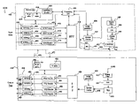
- FIG. 4 illustrates an ADSL transmission system 400 in accordance with an embodiment of the present invention.
- the system has an embodiment of a transmitter located at one end of the system, for example at a central office that accesses a high speed data network, in accordance with one aspect of the present invention and an embodiment of a receiver 404 located at the other end of the system, for example a remote location such as a customer premises having access to the customer's data terminal equipment.
- the locations of the transmitter 402 and receiver 404 may be reversed.
- the transmitter 402 and the receiver 404 may each be embodied in a processor such as a digital signal processor (DSP). Additionally, one or more of the elements shown in FIG.
- DSP digital signal processor
- any combination of the elements of the transmitter, the receiver or both may also be implemented in software or in a single discrete unit such as a DSP chip.
- the transmitter 402 comprises a memory 440 having a ⁇ b i , g i ⁇ table, a table of the set of input bits ⁇ X i ⁇ that will be encoded to represent the Q-mode signal, and a table of sets of candidate ⁇ Q i ⁇ for each bin used during SHOWTIME as indicated by the ⁇ b i , g i ⁇ table.
- a processing unit 492 is communicatively coupled to the memory 440 , the bit-to-symbol encoder 433 , Inverse Fast Fourier Transform Module 418 , the PRBS generator 420 , and the power detector 435 .
- the processing unit performs control functions, message handling, and executes instructions for performing processing associated with PAR minimization methods or the transmission of data.
- a bit-to-symbol encoder 433 accesses the memory 440 and encodes the set of input bits ⁇ X i ⁇ to its corresponding PAR optimized or PAR minimized set of constellation points ⁇ Q i ⁇ , which are transferred to an Inverse Fast Fourier Transform Module 418 that transforms the set ⁇ Q i ⁇ to time domain symbols.
- the symbols are inverted by a symbol inverter 424 under the control of a pseudo-random (PRBS) generator 420 .
- PRBS pseudo-random
- the PRBS generator may be disabled.
- the symbol inverter provides the equivalent of a logical XOR function.
- the transmitter 402 further comprises a power detector 435 for measuring the peak power and average power at either the IFFT output 437 or the line driver output 439 .
- the power detector 435 sends data to the processing unit 492 .
- the bit-to-symbol 433 encoder comprises a mapping module 436 comprising logic 402 , 404 , 406 , 408 for mapping an input data stream, in this example zeroes, to the set of input bits ⁇ X i ⁇ .
- the logic 402 , 404 , 406 , 408 implements an XOR operation on the input data bits and X i for each bin used during SHOWTIME.
- the output(i) will be X i which is then encoded to Q i in the set of optimum ⁇ Q i ⁇ points by the QAM encoders 410 , 412 , 414 , 416 . If Trellis encoding is used, it is performed before the XOR operation. More specifically, both uncoded bits and coded bits are XORed with X i .
- the receiver 404 receives the time domain symbols in analog form from the end of the transmission path 434 B, e.g. a telephone line.
- An analog filter 442 receives the symbols, filters them, and forwards them to an analog to digital converter 444 for conversion to digital form.
- the symbols now in digital form are forwarded to a time-domain equalizer (TEQ) 446 .
- TEQ time-domain equalizer
- the TEQ 446 compensates for channel distortion in the time-domain such that the combined impulse response of the channel and the TEQ 446 is within the length of a cyclic prefix.
- the cyclic prefix is removed after TEQ 446 and the bits are sent to symbol inverter 448 under the control of a PRBS generator 410 which may also be disabled in other embodiments.
- the (fast Fourier transform) FFT demodulator 450 receives the bits from the symbol inverter 448 and separates and demodulates all the sub-channels. After the FFT demodulator 450 , the bits for each bin or sub-channel are forwarded to a Symbol to Bit Decoder module 482 comprising symbol to bit decoders 452 , 454 , 458 , 460 .
- the frequency domain equalizer (FEQ) is included as part of this module, but it will be apparent to those of skill in the art that the FEQ can be implemented separately as well.
- a FEQ provides further compensation for amplitude and phase distortion for an associated sub-channel.
- a FEQ has coefficients that characterize the distortion of an associated sub-channel and can be used to compensate, or equalize that distortion.
- Each symbol decoder 452 , 454 , 458 , 460 of the Symbol to Bit Decoder module 482 decides which signal point from the constellation for the bin is represented by the received signal.
- the actual structure of the decoder may vary depending on the encoding scheme used by the transmitter 402 .
- the symbol decoder can be a slicer.
- a Viterbi decoder may be used for making the decisions to improve the reliability of the decision.
- Each symbol decoder converts each symbol to X i , the binary bits representing the point Q i .
- the Symbol to Bit Decoder module 482 further comprises a demapping module 490 comprising logic 480 , 484 , 486 , 488 for mapping X i back to its original value in the input data stream that was transmitted. In the example above zeroes are transmitted during Q-mode.
- the logic 480 , 484 , 486 , 488 implements an XOR operation on each of the X i for each bin used during SHOWTIME.
- the receiver has the ⁇ X i ⁇ stored in its memory 464 .
- the transmitter 402 communicates the set of input bits to the receiver 404 , for example the transmitter sends a message including the set ⁇ X i ⁇ .
- the output(i) will be input(i), the original data value transmitted.
- a Viterbi decoder is used, the coded bits are adjusted to compensate for the XOR operation on coded bits in the Trellis encoder.
- the uncoded bits are XORed after the decoder. As a result, the receiver will get all zero bits as output in the Q-mode.
- the receiver in this example may forward this data to customer data terminal equipment.
- Second generation ADSL standards provide for reconfiguration of the ADSL modem parameters during SHOWTIME (normal operation) without having to resort to initialization.
- the receiver 404 initiates reconfiguration changes. These reconfiguration changes can occur at either the physical media dependent (PMD) sublayer or the physical media specific transmission convergence (PMS-TC) sublayer or both. Some of the reconfiguration changes do not impact the ⁇ b i , g i ⁇ tables while others do. Online reconfiguration due to bit swapping and dynamic rate adaptation result in modification of the ⁇ b i , g i ⁇ tables.
- the receiver 404 communicates whether bit swapping or dynamic rate adjustment is appropriate, and whether the fine grain adjustments or transmit gain factors g i should be scaled.
- FIG. 4 illustrates a message 470 from the receiver to the transmitter and another message 472 from the transmitter 402 to the receiver 404 .
- Message handling between modems in DSL systems including ADSL systems are known to those skilled in the art.
- a reconfiguration message may be used to inform the other side using the existing ADSL overhead channel (AOC) protocol.
- Examples of messages 470 from the receiver include a reconfiguration message such as a bit swap request or a dynamic rate adjustment request.
- An example of a message 472 from the transmitter is an acknowledgement of the request.
- a PAR minimization algorithm is run based on the new ⁇ b i , g i ⁇ table for a subset of bins including the modified bins.
- the result would be a new set of input bits X i 's for certain sub-carriers.
- These new input bit mappings would then be included in a reconfiguration message to inform the other side.
- the reconfiguration message using the existing AOC protocol sends only those X i 's that have been modified to reduce the transmission overhead of this information over the AOC channel. These X i 's would take effect in the remote receiver at the start of a known symbol (for synchronization) along with the new ⁇ b i , g i ⁇ table.
- Minimizing the PAR of the transmitted time-domain signal is performed using a PAR minimization algorithm.
- the PAR minimization algorithm is executed in training after the transmitter receives the bit and gain table ⁇ b i ,g i ⁇ . Vendors may develop their own PAR minimization algorithms and make compromises between complexity and performance. Vendors can also choose not to save power in the Q-mode by simply choosing all X i bits be 0 for all the XOR operations. In this embodiment, the present invention provides a technique that assures backwards compatibility to the older version ADSL modems which do not have a Q-mode function.
- a system for minimizing the PAR of the Q-mode signal comprises a processing unit for executing instructions, including those of a PAR minimization method, that is communicatively coupled to a memory, a bit-to-symbol encoder, an Inverse Fast Fourier Transform Module, and a power detector to receive data from the power detector.
- the bit-to-symbol encoder for converting a set of input bits for a number of bins to symbols that are forwarded to an inverse fast-Fourier transformer for transforming the symbols into a time-domain signal, a power detector for detecting the average power and peaks outside the peak threshold, and a memory for storing results.
- the power detector may be placed at the output of the IFFT or at the output of a line driver for taking measurements.
- the transmitter 402 of FIG. 4 illustrates an embodiment of such a system comprising these elements 433 , 418 , 440 , 435 .
- the system may also be implemented offline from the transmitter. For example, if a PAR minimization is performed due to an online reconfiguration such as bit swapping, the PAR minimization may be performed by a system coupled to the transmitter that downloads the new set of input bits ⁇ X i ⁇ to the memory 440 of the transmitter 402 .
- FIG. 5 illustrates a random quadrant selection PAR minimization method 500 that may be used in accordance with an embodiment of the present invention.
- a random number generator may be used to randomly select 502 a quadrant from which a Q i point is selected from the candidate set ⁇ Q i ⁇ for each of the N bins used during the payload data carrying mode (e.g. SHOWTIME). For example, the random number generator may generate 2 bits for each bin to select a quadrant, in effect randomly choosing the phase of the Q i point.
- An inverse Fourier transform or an inverse fast-Fourier transform is performed 504 on the randomly selected set of points for the used bins to generate a time domain signal x(N).
- the set of input bits ⁇ X i ⁇ corresponding to the combination of Q i satisfying the PAR threshold is determined 510 , stored 512 in memory for a transmitter, communicated 514 to a receiver, and stored 516 in memory at the receiver. However, if there are one or more peaks not within the threshold causing an unacceptable PAR, it is determined 507 whether a maximum number of iterations has been exceeded. If not, another set of quadrants is randomly selected 502 and the process repeats until a signal with an acceptable PAR is found or the iterations limit is met.
- FIG. 6 illustrates an optimum subset rotation PAR minimization algorithm or method 600 that may be used in accordance with an embodiment of the present invention.
- This method of optimum subset rotation provides less complexity by not using an IFFT for each iteration.
- the N bins used during the payload data carrying state are divided 602 into four subsets S 1 , S 2 , S 3 and S 4 .
- Four smaller IFFTs are performed 604 first on S 1 , S 2 , S 3 and S 4 , respectively, to generate time domain signals s 1 , s 2 , s 3 and s 4 .
- Each of these subsets will be rotated through the four quadrants.
- a loop 606 construct illustrates this example of processing, but other processing constructs such as an If-then construct may also be used.
- the resulting PAR for this combination is determined 610 .
- each of the signals is then multiplied 608 by a different phase multiplier 612 so as to rotate the phase of the signal 90°.
- Each of these signals s 1 , s 2 , s 3 and s 4 are combined 608 , and a resulting PAR for this combination is determined 610 . Rotation of the signals occurs through all four quadrants.
- the compromise between complexity and performance is simplified. A small number of cases can be searched, and a smaller PAR reduction can be obtained, or vice versa.
- the N bins may be divided into more subsets (e.g., 8,16, . . . ) to possibly achieve more PAR reduction at the cost of increased complexity.
- FIG. 7 shows a PAR reduction method by sign-inversion of intermediate results using a 2-stage inverse fast-Fourier transformer in accordance with an embodiment of the present invention.
- the input used frequency bins X(N) are transformed from the frequency domain to the time domain signal x(N) by an inverse fast-Fourier transform (IFFT).
- IFFT inverse fast-Fourier transform
- the frequency-domain input X(N) is placed column-wise into a rectangular N 2 ⁇ N 1 matrix and input to first transform 22 .
- First transform 22 contains N 1 transforms, and each transform is an N 2 -point IFFT transform. Each of the N 1 transforms performs an N 2 -point IFFT given by the equation:
- Second transform 24 contains N 2 transforms, each being an N 1 -point IFFT. Second transform 24 performs the equation for the k-th N 1 -point IFFT:
- the input subset has one or more rows of N 2 inputs. Since the first transformer 22 is an N 2 -point IFFT that operates on a row of N 2 inputs, sign inversion of an input subset causes the corresponding intermediate outputs to invert. Since all of the inputs in a subset are inverted, each of the corresponding intermediate outputs is also inverted.
- the inverted intermediate subset Q is shown as ⁇ Y(Q).
- the remaining, un-inverted intermediate results Y(i) and the inverted intermediate subset ⁇ Y(Q) are input to second transformer 24 to generate the revised output x(N).
- FIG. 8 is a flowchart for an intermediate-result sign-inversion for PAR reduction method in accordance with an embodiment of the present invention.
- An N 2 -point IFFT is performed on each row of N 2 inputs to produce a row of N 2 intermediate-result outputs Y(i,k).
- a total of N 1 of the N 2 -point IFFTs are performed 50 . This is the first transformer.
- the intermediate results Y(i,k) are stored for later use, but are also sent to the second transformer.
- N 1 -point IFFTs are performed on each column of N 1 of the intermediate results Y(i,k).
- a total of N 2 of the N 1 -point transforms are performed 52 , yielding the output matrix x(i,k).
- the matrix (i, k) is scanned for peaks, and the largest peak (the output with the highest absolute value) is detected 46 . This peak is located at time N 0 .
- the peak's voltage is compared to the peak threshold 54 . If the largest peak is within the peak threshold, then PAR is acceptable, and sign inversion is not required.
- the set of input bits ⁇ X N ⁇ corresponding to the time-domain outputs x(N) is determined, stored in a memory (e.g. 440 ) for a transmitter (e.g. 402 ), communicated (e.g. via a message) to a receiver (e.g. 404 ) and stored for the receiver in its memory (e.g. 464 ).
- one or more of the subsets need to be inverted to try to reduce the peak's voltage.
- One set of the subsets is chosen 56 for inversion. Rather than randomly choose a set of subsets, the effects of the sign inversion of sets of subsets on the peak value are evaluated first to find out which sign inversion pattern gives the best peak reduction effect.
- the final outputs are re-calculated. Rather than simply re-execute the entire IFFT, or even re-execute the second transform, the outputs are adjusted.
- n0 is the index of the peak output
- each output x(i,k) has ⁇ 2Y(i 1 ,k) e j2 ⁇ ili 0 /N 1 added 62 . All N outputs are adjusted instead of recalculating entire N 2 N 1 -point IFFT.
- N 1 -point IFFT Calculation is reduced since computing and adding this term to adjust the output is simpler than recalculating the entire N 1 -point IFFT when N 1 is reasonably large. For the sign inversion of each subset, one adjusting term is added. The complexity is thus proportional to the number of subsets inverted. Typically, the maximum number of subsets inverted can be limited. When N 1 is very small the N 1 -point IFFT can simply be re-calculated.
- FIG. 9 illustrates a sequential quadrant optimization PAR minimization method 900 using a bin-by-bin approach that may be used in accordance with an embodiment of the present invention.
- An initial signal such as the combination of Q i points from the first quadrant for each of the N bins designated to carry payload data may be used as a starting signal.
- points from a different quadrant may also be used or a combination of points from different quadrants may also be used.
- a candidate point Q i for the bin is selected having a certain phase 904 .
- An IFFT is performed 906 on the N bins using candidate point w k Q i for the ith bin.
- the PAR is determined 908 for the resulting time domain signal x(N).
- the loop counter k is incremented 912 by one so that 90° is effectively added to the phase multiplier. In this way, the PAR of the time domain signal as effected by the Q i point in all four quadrants is determined.
- the point w k Q i for the ith bin resulting in the minimum PAR of the time domain signal is selected 914 . It is determined 916 if the PAR for the signal x(N) is below a threshold. If not, an index i is incremented 920 , and the previous processing is repeated for the next bin. This operation is repeated until the PAR is below the desired threshold value or all the elements of the set of bins are visited. If the PAR for the signal x(N) is below a threshold, the set of input bits ⁇ X i ⁇ corresponding to this combination of Q i candidate points is determined 918 and stored 918 .
- the line characteristics may not change dramatically, and only a few carriers may need modification of ⁇ b i , g i ⁇ .
- a localized PAR minimization may be run to find the optimal phases for the modified bins or the modified bins and a few nearby channels or the modified bins and a subset of a few randomly selected channels to obtain a resulting low PAR signal.
- the sequential quadrant optimization method using a bin-by-bin approach is an efficient algorithm for this purpose. The complexity of such a local minimization is low.
- FIG. 10 illustrates a sequential quadrant optimization PAR minimization algorithm 1000 using a set-by-set approach that may be used in accordance with an embodiment of the present invention.
- This algorithm combines aspects of the optimum subset rotation method and the sequential quadrant optimization method.
- N bins are divided 1002 into M subsets S 1 , S 2 , . . . S M .
- optimization is performed set-by-set sequentially.
- the PAR can be minimized by selecting the best w k for that set and moving on to the next set. This operation is repeated until the PAR is below the desired value or all the elements of the set of bins are visited.
- An IFFT is performed 1008 on the M subsets using the subset w k S i .
- the PAR is determined 1010 for the resulting time domain signal.
- An index k is incremented 1012 by one. In this way, the PAR of the time domain signal as affected by the Si subset in all four quadrants is determined.
- the subset w k S i for the ith bin resulting in the minimum PAR of the time domain signal is selected 1014 . It is determined 1016 if the PAR for the signal is below a threshold. If not, an index i is incremented 1020 , and the previous processing is repeated for the next bin. This operation is repeated until the PAR is below the desired threshold value or all the subsets of bins have been processed. If the PAR for the time domain signal is below the threshold, the set of input bits ⁇ X i ⁇ corresponding to this combination of Q i candidate points in the subsets is determined 1018 and stored 1018 .
- FIGS. 11 and 12 show the result of SQO, where at each iteration the quadrant for only one bin is optimized.
- the PAR minimization is at the IFFT output.
- the PAR is increased at the line driver input due to the effect of the filters. This degradation is undesirable.
- the PAR minimization is done at the line driver input. It can be seen that although the PAR at the IFFT output is increased, the PAR at the line driver is small. Also shown in FIG. 12 is the re-optimization after online reconfiguration at iteration 220 where 3 bins have changed b i .
- a REVERB signal is simulated, and the PAR is measured at the IFFT output and at the line driver input.
- the degradation in PAR due to analog and digital filters is about 1 dB.
- a partial REVERB is also simulated where only half of the bins are used.
- the PAR at the IFFT output is about 0.8 dB worse than a REVERB signal.
- PAR is about 9 dB. From simulation results, it can be seen that PAR reduction at line driver input is desirable, and the PAR there can be reduced to below 7 dB at reasonable complexity.
Abstract
Description
| TABLE 1 |
| QAM Point with Power Closest to Average Power |
| bi | Q (show in 1st quadrant only) | # of Q's | Power difference in dB |
| 2 | (1, 1) | 4 | 0 |
| 3 | (1, 3) | 4 | +2.2 |
| 4 | (1, 3), (3, 1) | 8 | 0 |
| 5 | (3, 3) | 4 | −0.46 |
| 6 | (3, 5), (5, 3) | 8 | −0.92 |
| 7 | (1, 9), (9, 1) | ≧8 | 0 |
| 8 | (1, 13), (7, 11), (11, 7), (13, 1) | ≧16 | 0 |
| 9 | (13, 13), (7, 17), (17, 7) | ≧12 | +0.10 |
| 10 | (7, 25), (25, 7) | ≧8 | −0.05 |
| 11 | (31, 19), (19, 31) | ≧8 | 0 |
| 12 | (37, 37), (23, 47), (47, 23), (11, | ≧20 | ±0.01 |
| 51), (51, 11) | |||
| 13 | (23, 69), (69, 23) | ≧8 | 0 |
| 14 | (97, 39), (39, 97), (27, 101), (101, | ≧16 | 0.003 |
| 27) | |||
| 15 | (43, 139), (49, 137), (59, 133), | ≧32 | 0.002 |
| (71, 127) . . . | |||
for the i-th N2-point IFFT
| TABLE 2 |
| Results for PAR Optimization Algorithms |
| Digital Output | Line Driver Input | |
| Algorithm | PAR [dB] | PAR [dB] |
| Algorithm 1 (RQS) (IFFT output) | 8.1 | 9.9 |
| Algorithm 1 (RQS) (Line Driver | 10.3 | 8.9 |
| Input) | ||
| Algorithm 2 (OSR) (IFFT output) | 7.9 | 9.9 |
| Algorithm 2 (OSR) (Line Driver | 8.3 | 8.5 |
| Input) | ||
| Algorithm 3 (SQO) (IFFT output) | 6.1 | 9.5 |
| Algorithm 3 (SQO) (Line Driver | 7.8 | 6.9 |
| Input) | ||
| REVERB | 7.7 | 8.6 |
| Partial REVERB | 8.5 | 9.0 |
Claims (8)
Priority Applications (1)
| Application Number | Priority Date | Filing Date | Title |
|---|---|---|---|
| US10/118,859 US7177350B1 (en) | 2001-04-06 | 2002-04-08 | Receiver transparent quiescent mode operation in a DSL transmission system |
Applications Claiming Priority (2)
| Application Number | Priority Date | Filing Date | Title |
|---|---|---|---|
| US28199801P | 2001-04-06 | 2001-04-06 | |
| US10/118,859 US7177350B1 (en) | 2001-04-06 | 2002-04-08 | Receiver transparent quiescent mode operation in a DSL transmission system |
Publications (1)
| Publication Number | Publication Date |
|---|---|
| US7177350B1 true US7177350B1 (en) | 2007-02-13 |
Family
ID=37719727
Family Applications (1)
| Application Number | Title | Priority Date | Filing Date |
|---|---|---|---|
| US10/118,859 Expired - Fee Related US7177350B1 (en) | 2001-04-06 | 2002-04-08 | Receiver transparent quiescent mode operation in a DSL transmission system |
Country Status (1)
| Country | Link |
|---|---|
| US (1) | US7177350B1 (en) |
Cited By (8)
| Publication number | Priority date | Publication date | Assignee | Title |
|---|---|---|---|---|
| US20050018702A1 (en) * | 2003-07-09 | 2005-01-27 | Industrial Technology Research Institute | PAPR reduction method using bit reallocation |
| US7486608B1 (en) * | 2002-11-14 | 2009-02-03 | Ikanos Communications, Inc. | Efficient implementation of low power mode in digital subscriber line (DSL) transceivers |
| US20090180526A1 (en) * | 2008-01-14 | 2009-07-16 | Futurewei Technologies, Inc. | Power Reduction for Digital Subscriber Line |
| US20090279620A1 (en) * | 2008-05-09 | 2009-11-12 | Infineon Technologies Ag | Data communication |
| US20100290558A1 (en) * | 2001-03-27 | 2010-11-18 | Aware, Inc. | Systems and methods for implementing receiver transparent q-mode |
| US20120093241A1 (en) * | 2010-10-15 | 2012-04-19 | Ikanos Communications, Inc. | Dsl alien noise reduction |
| US20120281712A1 (en) * | 2011-05-02 | 2012-11-08 | GM Global Technology Operations LLC | Transmitting-receiving apparatuses and methods for transmitting and receiving data |
| US10887450B1 (en) * | 2018-09-06 | 2021-01-05 | Adtran, Inc. | Systems and methods for locating faults in a telecommunication line using line test data |
Citations (19)
| Publication number | Priority date | Publication date | Assignee | Title |
|---|---|---|---|---|
| US5515398A (en) * | 1994-03-15 | 1996-05-07 | U.S. Robotics, Inc. | Modem line probing signal techniques |
| US5838720A (en) | 1996-02-23 | 1998-11-17 | Teletransactions, Inc. | Transceiver control with sleep mode operation |
| US6064193A (en) * | 1997-07-17 | 2000-05-16 | Tektronix, Inc. | Method and apparatus for measuring the mean square value of an electrical signal |
| US6075814A (en) | 1997-05-09 | 2000-06-13 | Broadcom Homenetworking, Inc. | Method and apparatus for reducing signal processing requirements for transmitting packet-based data with a modem |
| US6104707A (en) | 1989-04-28 | 2000-08-15 | Videocom, Inc. | Transformer coupler for communication over various lines |
| US6236674B1 (en) | 1996-02-23 | 2001-05-22 | Teletransactions, Inc. | Transceiver control with sleep mode operation |
| US6240141B1 (en) | 1998-05-09 | 2001-05-29 | Centillium Communications, Inc. | Lower-complexity peak-to-average reduction using intermediate-result subset sign-inversion for DSL |
| US6414989B1 (en) * | 1999-09-10 | 2002-07-02 | Conexant Systems, Inc. | Upstream PCM transmission for a modem system |
| US6445730B1 (en) * | 1998-01-26 | 2002-09-03 | Aware, Inc. | Multicarrier transmission system with low power sleep mode and rapid-on capability |
| US6463094B2 (en) | 1998-04-14 | 2002-10-08 | Smart Link Ltd. | Point-to-point secure modem and method |
| US6490269B1 (en) * | 1998-07-22 | 2002-12-03 | Sony Corporation | OFDM signal generation method and OFDM signal generation apparatus |
| US6584160B1 (en) * | 1998-08-13 | 2003-06-24 | Globespanvirata, Inc. | System and method for reducing the effects of clipping in a DMT transceiver |
| US6665308B1 (en) | 1995-08-25 | 2003-12-16 | Terayon Communication Systems, Inc. | Apparatus and method for equalization in distributed digital data transmission systems |
| US6693972B1 (en) | 1999-12-07 | 2004-02-17 | Richard Thomas Flanagan | Data apparatus for maintaining analog line signal during a data sample underrun condition |
| US6711207B1 (en) * | 1999-03-11 | 2004-03-23 | Globespanvirata, Inc. | System and method for reduced power consumption in digital subscriber line modems |
| US6721355B1 (en) * | 1999-12-20 | 2004-04-13 | Nortel Networks Limited | Method and apparatus for adaptive power management in a modem |
| US6819719B2 (en) * | 2000-02-24 | 2004-11-16 | Alcatel | Method to transfer trellis code modulated digital data over a digital subscriber line, and related modulator and demodulator devices |
| US6862321B2 (en) * | 2000-04-03 | 2005-03-01 | Victor Company Of Japan, Ltd. | Method and apparatus for generating transmission signal by processing which includes digital quadrature modulation |
| US6898235B1 (en) * | 1999-12-10 | 2005-05-24 | Argon St Incorporated | Wideband communication intercept and direction finding device using hyperchannelization |
-
2002
- 2002-04-08 US US10/118,859 patent/US7177350B1/en not_active Expired - Fee Related
Patent Citations (20)
| Publication number | Priority date | Publication date | Assignee | Title |
|---|---|---|---|---|
| US6104707A (en) | 1989-04-28 | 2000-08-15 | Videocom, Inc. | Transformer coupler for communication over various lines |
| US5515398A (en) * | 1994-03-15 | 1996-05-07 | U.S. Robotics, Inc. | Modem line probing signal techniques |
| US6665308B1 (en) | 1995-08-25 | 2003-12-16 | Terayon Communication Systems, Inc. | Apparatus and method for equalization in distributed digital data transmission systems |
| US5838720A (en) | 1996-02-23 | 1998-11-17 | Teletransactions, Inc. | Transceiver control with sleep mode operation |
| US6236674B1 (en) | 1996-02-23 | 2001-05-22 | Teletransactions, Inc. | Transceiver control with sleep mode operation |
| US6075814A (en) | 1997-05-09 | 2000-06-13 | Broadcom Homenetworking, Inc. | Method and apparatus for reducing signal processing requirements for transmitting packet-based data with a modem |
| US6445731B1 (en) * | 1997-05-09 | 2002-09-03 | Broadcom Homenetworking, Inc. | Method and apparatus for reducing signal processing requirements for transmitting packet-based data with a modem |
| US6064193A (en) * | 1997-07-17 | 2000-05-16 | Tektronix, Inc. | Method and apparatus for measuring the mean square value of an electrical signal |
| US6445730B1 (en) * | 1998-01-26 | 2002-09-03 | Aware, Inc. | Multicarrier transmission system with low power sleep mode and rapid-on capability |
| US6463094B2 (en) | 1998-04-14 | 2002-10-08 | Smart Link Ltd. | Point-to-point secure modem and method |
| US6240141B1 (en) | 1998-05-09 | 2001-05-29 | Centillium Communications, Inc. | Lower-complexity peak-to-average reduction using intermediate-result subset sign-inversion for DSL |
| US6490269B1 (en) * | 1998-07-22 | 2002-12-03 | Sony Corporation | OFDM signal generation method and OFDM signal generation apparatus |
| US6584160B1 (en) * | 1998-08-13 | 2003-06-24 | Globespanvirata, Inc. | System and method for reducing the effects of clipping in a DMT transceiver |
| US6711207B1 (en) * | 1999-03-11 | 2004-03-23 | Globespanvirata, Inc. | System and method for reduced power consumption in digital subscriber line modems |
| US6414989B1 (en) * | 1999-09-10 | 2002-07-02 | Conexant Systems, Inc. | Upstream PCM transmission for a modem system |
| US6693972B1 (en) | 1999-12-07 | 2004-02-17 | Richard Thomas Flanagan | Data apparatus for maintaining analog line signal during a data sample underrun condition |
| US6898235B1 (en) * | 1999-12-10 | 2005-05-24 | Argon St Incorporated | Wideband communication intercept and direction finding device using hyperchannelization |
| US6721355B1 (en) * | 1999-12-20 | 2004-04-13 | Nortel Networks Limited | Method and apparatus for adaptive power management in a modem |
| US6819719B2 (en) * | 2000-02-24 | 2004-11-16 | Alcatel | Method to transfer trellis code modulated digital data over a digital subscriber line, and related modulator and demodulator devices |
| US6862321B2 (en) * | 2000-04-03 | 2005-03-01 | Victor Company Of Japan, Ltd. | Method and apparatus for generating transmission signal by processing which includes digital quadrature modulation |
Non-Patent Citations (3)
| Title |
|---|
| Dagdeviren, "Proposed Peak To Average Ratio Reduction Technique For G.Lite and G.dmt", ITU Study Group 15, NF-074, May 11, 1998, 2 pages. |
| ITU-Telecommunication Standardization Sector Temporary Document IC-036, "G.gen: G.dmt.bis; G.lite.bis: : Receiver Transparent Q-mode," 8 pages, Irvine, CA, Apr. 9-13, 2001. |
| ITU-Telecommunication Standardization Sector Temporary Document MA-043, "G.gen.bis-Improved Suspend Type Quiescent Mode," pp. 1-13, Melbourne, Australia, Mar. 29-Apr. 1999. |
Cited By (16)
| Publication number | Priority date | Publication date | Assignee | Title |
|---|---|---|---|---|
| US20100290558A1 (en) * | 2001-03-27 | 2010-11-18 | Aware, Inc. | Systems and methods for implementing receiver transparent q-mode |
| US10419059B2 (en) | 2001-03-27 | 2019-09-17 | Tq Delta, Llc | Systems and methods for implementing receiver transparent Q-mode |
| US9191039B2 (en) | 2001-03-27 | 2015-11-17 | Tq Delta, Llc | Randomization using an XOR scrambler in multicarrier communications |
| US8335271B2 (en) * | 2001-03-27 | 2012-12-18 | Tq Delta, Llc | Systems and methods for implementing receiver transparent Q-mode |
| US8792574B2 (en) | 2001-03-27 | 2014-07-29 | TQ Detla, LLC | Systems and methods for implementing receiver transparent Q-mode |
| US7486608B1 (en) * | 2002-11-14 | 2009-02-03 | Ikanos Communications, Inc. | Efficient implementation of low power mode in digital subscriber line (DSL) transceivers |
| US20050018702A1 (en) * | 2003-07-09 | 2005-01-27 | Industrial Technology Research Institute | PAPR reduction method using bit reallocation |
| US7313195B2 (en) * | 2003-07-09 | 2007-12-25 | Industrial Technology Research Institute | PAPR reduction method using bit reallocation |
| US20090180526A1 (en) * | 2008-01-14 | 2009-07-16 | Futurewei Technologies, Inc. | Power Reduction for Digital Subscriber Line |
| US8442131B2 (en) * | 2008-01-14 | 2013-05-14 | Futurewei Technologies, Inc. | Power reduction for digital subscriber line |
| US20090279620A1 (en) * | 2008-05-09 | 2009-11-12 | Infineon Technologies Ag | Data communication |
| US8068547B2 (en) | 2008-05-09 | 2011-11-29 | Lantiq Deutschland Gmbh | Data communication |
| US8848504B2 (en) * | 2010-10-15 | 2014-09-30 | Ikanos Communications, Inc. | DSL alien noise reduction |
| US20120093241A1 (en) * | 2010-10-15 | 2012-04-19 | Ikanos Communications, Inc. | Dsl alien noise reduction |
| US20120281712A1 (en) * | 2011-05-02 | 2012-11-08 | GM Global Technology Operations LLC | Transmitting-receiving apparatuses and methods for transmitting and receiving data |
| US10887450B1 (en) * | 2018-09-06 | 2021-01-05 | Adtran, Inc. | Systems and methods for locating faults in a telecommunication line using line test data |
Similar Documents
| Publication | Publication Date | Title |
|---|---|---|
| US7720167B2 (en) | Power save mode transition using loading translation function | |
| US9628312B2 (en) | OFDM communication system and method having a reduced peak-to-average power ratio | |
| US6845082B2 (en) | Peak to average power ratio reduction in communication systems | |
| US7403569B2 (en) | Efficient low-power mode for multicarrier communications | |
| US6925128B2 (en) | Method and apparatus for reducing a peak-to-average power ratio in an orthogonal frequency division multiplex signal | |
| US5835536A (en) | Method and apparatus for reducing peak-to-average requirements in multi-tone communication circuits | |
| AU696798B2 (en) | Frame synchronization in multicarrier transmission systems | |
| Jayalath et al. | Reduced complexity PTS and new phase sequences for SLM to reduce PAP of an OFDM signal | |
| US6580761B2 (en) | Coding technique in discrete multi-tone (DMT) based communications systems | |
| Sarowa et al. | Evolution of PAPR reduction techniques: A wavelet based OFDM approach | |
| Chow et al. | Mitigating clipping noise in multi-carrier systems | |
| Wu | Selected mapping and partial transmit sequence schemes to reduce PAPR in OFDM systems | |
| US7177350B1 (en) | Receiver transparent quiescent mode operation in a DSL transmission system | |
| CN1984110B (en) | Method for decreasing peak equilibrium ratio and orthogonal frequency division multiplexing system | |
| US7486608B1 (en) | Efficient implementation of low power mode in digital subscriber line (DSL) transceivers | |
| Orović et al. | Analysis of power consumption in OFDM systems | |
| KR20010042557A (en) | System, device and method for improving a defined property of transform-domain signals | |
| Shankar et al. | Hadamard based SLM using genetic algorithm fo PAPR reduction in OFDM systems | |
| Singh et al. | Reducing Peak to Average Power Ratio of OFDM by Using Selected Mapping | |
| Jamieson et al. | SPCp1-04: Bit Mapping and Error Insertion for FEC Based PAPR Reduction in OFDM Signals | |
| Pierrugues et al. | DMT performance improvement based on clustering modulation, applications to ADSL | |
| Bhagwatkar et al. | Performance of OFDM system Modified SLM Technique with DQPSK | |
| Ren | An Improved Selected Mapping Scheme for PAPR Reduction in OFDM Systems | |
| Agrawal et al. | PAPR Reduction of an OFDM Signal using Partial Transmit Sequences (PTS) Technique | |
| Malik et al. | PAPR Reduction in OFDM system by Modified DFT spreading technique with Pulse shaping |
Legal Events
| Date | Code | Title | Description |
|---|---|---|---|
| AS | Assignment |
Owner name: CENTILLIUM COMMUNICATIONS, INC., CALIFORNIA Free format text: ASSIGNMENT OF ASSIGNORS INTEREST;ASSIGNORS:LONG, GUOZHU;RASHID-FARROKHI, FARROKH;ABBAS, SYED;REEL/FRAME:013197/0707;SIGNING DATES FROM 20020616 TO 20020624 |
|
| FEPP | Fee payment procedure |
Free format text: PAT HOLDER NO LONGER CLAIMS SMALL ENTITY STATUS, ENTITY STATUS SET TO UNDISCOUNTED (ORIGINAL EVENT CODE: STOL); ENTITY STATUS OF PATENT OWNER: LARGE ENTITY |
|
| AS | Assignment |
Owner name: IKANOS COMMUNICATIONS, INC., CALIFORNIA Free format text: ASSIGNMENT OF ASSIGNORS INTEREST;ASSIGNOR:CENTILLIUM COMMUNICATIONS INC.;REEL/FRAME:021354/0963 Effective date: 20080213 |
|
| FPAY | Fee payment |
Year of fee payment: 4 |
|
| FPAY | Fee payment |
Year of fee payment: 8 |
|
| AS | Assignment |
Owner name: ALCATEL-LUCENT USA, INC., NEW JERSEY Free format text: NOTICE OF GRANT OF SECURITY INTEREST IN PATENTS;ASSIGNOR:IKANOS COMMUNICATIONS, INC.;REEL/FRAME:035581/0710 Effective date: 20150430 |
|
| AS | Assignment |
Owner name: SILICON VALLEY BANK, CALIFORNIA Free format text: SECURITY INTEREST;ASSIGNOR:IKANOS COMMUNICATIONS, INC.;REEL/FRAME:035874/0351 Effective date: 20150602 |
|
| AS | Assignment |
Owner name: IKANOS COMMUNICATIONS, INC., CALIFORNIA Free format text: RELEASE BY SECURED PARTY;ASSIGNOR:ALCATEL-LUCENT USA, INC.;REEL/FRAME:036732/0876 Effective date: 20150929 Owner name: IKANOS COMMUNICATIONS, INC., CALIFORNIA Free format text: RELEASE BY SECURED PARTY;ASSIGNOR:SILICON VALLEY BANK;REEL/FRAME:036733/0031 Effective date: 20150930 |
|
| FEPP | Fee payment procedure |
Free format text: MAINTENANCE FEE REMINDER MAILED (ORIGINAL EVENT CODE: REM.); ENTITY STATUS OF PATENT OWNER: LARGE ENTITY |
|
| LAPS | Lapse for failure to pay maintenance fees |
Free format text: PATENT EXPIRED FOR FAILURE TO PAY MAINTENANCE FEES (ORIGINAL EVENT CODE: EXP.); ENTITY STATUS OF PATENT OWNER: LARGE ENTITY |
|
| STCH | Information on status: patent discontinuation |
Free format text: PATENT EXPIRED DUE TO NONPAYMENT OF MAINTENANCE FEES UNDER 37 CFR 1.362 |
|
| FP | Lapsed due to failure to pay maintenance fee |
Effective date: 20190213 |