US7186264B2 - Method and apparatus for improving mitral valve function - Google Patents
Method and apparatus for improving mitral valve function Download PDFInfo
- Publication number
- US7186264B2 US7186264B2 US10/112,354 US11235402A US7186264B2 US 7186264 B2 US7186264 B2 US 7186264B2 US 11235402 A US11235402 A US 11235402A US 7186264 B2 US7186264 B2 US 7186264B2
- Authority
- US
- United States
- Prior art keywords
- coronary sinus
- elements
- straightening device
- mitral valve
- guidewire
- Prior art date
- Legal status (The legal status is an assumption and is not a legal conclusion. Google has not performed a legal analysis and makes no representation as to the accuracy of the status listed.)
- Expired - Fee Related
Links
Images


Classifications
-
- A—HUMAN NECESSITIES
- A61—MEDICAL OR VETERINARY SCIENCE; HYGIENE
- A61F—FILTERS IMPLANTABLE INTO BLOOD VESSELS; PROSTHESES; DEVICES PROVIDING PATENCY TO, OR PREVENTING COLLAPSING OF, TUBULAR STRUCTURES OF THE BODY, e.g. STENTS; ORTHOPAEDIC, NURSING OR CONTRACEPTIVE DEVICES; FOMENTATION; TREATMENT OR PROTECTION OF EYES OR EARS; BANDAGES, DRESSINGS OR ABSORBENT PADS; FIRST-AID KITS
- A61F2/00—Filters implantable into blood vessels; Prostheses, i.e. artificial substitutes or replacements for parts of the body; Appliances for connecting them with the body; Devices providing patency to, or preventing collapsing of, tubular structures of the body, e.g. stents
- A61F2/02—Prostheses implantable into the body
- A61F2/24—Heart valves ; Vascular valves, e.g. venous valves; Heart implants, e.g. passive devices for improving the function of the native valve or the heart muscle; Transmyocardial revascularisation [TMR] devices; Valves implantable in the body
- A61F2/2442—Annuloplasty rings or inserts for correcting the valve shape; Implants for improving the function of a native heart valve
- A61F2/2451—Inserts in the coronary sinus for correcting the valve shape
-
- A—HUMAN NECESSITIES
- A61—MEDICAL OR VETERINARY SCIENCE; HYGIENE
- A61F—FILTERS IMPLANTABLE INTO BLOOD VESSELS; PROSTHESES; DEVICES PROVIDING PATENCY TO, OR PREVENTING COLLAPSING OF, TUBULAR STRUCTURES OF THE BODY, e.g. STENTS; ORTHOPAEDIC, NURSING OR CONTRACEPTIVE DEVICES; FOMENTATION; TREATMENT OR PROTECTION OF EYES OR EARS; BANDAGES, DRESSINGS OR ABSORBENT PADS; FIRST-AID KITS
- A61F2/00—Filters implantable into blood vessels; Prostheses, i.e. artificial substitutes or replacements for parts of the body; Appliances for connecting them with the body; Devices providing patency to, or preventing collapsing of, tubular structures of the body, e.g. stents
- A61F2/02—Prostheses implantable into the body
- A61F2/24—Heart valves ; Vascular valves, e.g. venous valves; Heart implants, e.g. passive devices for improving the function of the native valve or the heart muscle; Transmyocardial revascularisation [TMR] devices; Valves implantable in the body
- A61F2/2442—Annuloplasty rings or inserts for correcting the valve shape; Implants for improving the function of a native heart valve
- A61F2/2466—Delivery devices therefor
-
- Y—GENERAL TAGGING OF NEW TECHNOLOGICAL DEVELOPMENTS; GENERAL TAGGING OF CROSS-SECTIONAL TECHNOLOGIES SPANNING OVER SEVERAL SECTIONS OF THE IPC; TECHNICAL SUBJECTS COVERED BY FORMER USPC CROSS-REFERENCE ART COLLECTIONS [XRACs] AND DIGESTS
- Y10—TECHNICAL SUBJECTS COVERED BY FORMER USPC
- Y10S—TECHNICAL SUBJECTS COVERED BY FORMER USPC CROSS-REFERENCE ART COLLECTIONS [XRACs] AND DIGESTS
- Y10S623/00—Prosthesis, i.e. artificial body members, parts thereof, or aids and accessories therefor
- Y10S623/902—Method of implanting
- Y10S623/903—Blood vessel
-
- Y—GENERAL TAGGING OF NEW TECHNOLOGICAL DEVELOPMENTS; GENERAL TAGGING OF CROSS-SECTIONAL TECHNOLOGIES SPANNING OVER SEVERAL SECTIONS OF THE IPC; TECHNICAL SUBJECTS COVERED BY FORMER USPC CROSS-REFERENCE ART COLLECTIONS [XRACs] AND DIGESTS
- Y10—TECHNICAL SUBJECTS COVERED BY FORMER USPC
- Y10S—TECHNICAL SUBJECTS COVERED BY FORMER USPC CROSS-REFERENCE ART COLLECTIONS [XRACs] AND DIGESTS
- Y10S623/00—Prosthesis, i.e. artificial body members, parts thereof, or aids and accessories therefor
- Y10S623/902—Method of implanting
- Y10S623/904—Heart
Definitions
- This invention relates to surgical methods and apparatus in general, and more particularly to surgical methods and apparatus for improving mitral valve function.
- Mitral valve repair is the procedure of choice to correct mitral regurgitation of all etiologies. With the use of current surgical techniques, between 70% and 95% of regurgitant mitral valves can be repaired. The advantages of mitral valve repair over mitral valve replacement are well documented. These include better preservation of cardiac function and reduced risk of anticoagulant-related hemorrhage, thromboembolism and endocarditis.
- mitral valve surgery requires an extremely invasive approach that includes a chest wall incision, cardiopulmonary bypass, cardiac and pulmonary arrest, and an incision on the heart itself to gain access to the mitral valve.
- a procedure is associated with high morbidity and mortality. Due to the risks associated with this procedure, many of the sickest patients are denied the potential benefits of surgical correction of mitral regurgitation. In addition, patients with moderate, symptomatic mitral regurgitation are denied early intervention and undergo surgical correction only after the development of cardiac dysfunction.
- Mitral regurgitation is a common occurrence in patients with heart failure and a source of important morbidity and mortality in these patients. Mitral regurgitation in patients with heart failure is caused by changes in the geometric configurations of the left ventricle, papillary muscles and mitral annulus. These geometric alterations result in incomplete coaptation of the mitral leaflets during systole. In this situation, mitral regurgitation is corrected by plicating the mitral valve annulus, either by sutures alone or by sutures in combination with a support ring, so as to reduce the circumference of the distended annulus and restore the original geometry of the mitral valve annulus.
- mitral valve annulus be reduced in radius by surgically opening the left atrium and then fixing sutures, or more commonly sutures in combination with a support ring, to the internal surface of the annulus; this structure is used to pull the annulus back into a smaller radius, thereby reducing mitral regurgitation by improving leaflet coaptation.
- This method of mitral valve repair effectively reduces mitral regurgitation in heart failure patients. This, in turn, reduces symptoms of heart failure, improves quality of life and increases longetivity.
- annuloplasty effectively reduces mitral regurgitation in heart failure patients. This, in turn, reduces symptoms of heart failure, improves quality of life and increases longetivity.
- the invasive nature of mitral valve surgery and the attendant risks render most heart failure patients poor surgical candidates.
- a less invasive means to increase leaflet coaptation and thereby reduce mitral regurgitation in heart failure patients would make this therapy available to a much greater percentage of patients.
- Mitral regurgitation also occurs in approximately 20% of patients suffering acute myocardial infarction.
- mitral regurgitation is the primary cause of cardiogenic shock in approximately 10% of patients who develop severe hemodynamic instability in the setting of acute myocardial infarction.
- Patients with mitral regurgitation and cardiogenic shock have about a 50% hospital mortality. Elimination of mitral regurgitation in these patients would be of significant benefit.
- patients with acute mitral regurgitation complicating acute myocardial infarction are particularly high-risk surgical candidates, and are therefore not good candidates for a traditional annuloplasty procedure.
- a minimally invasive means to effect a temporary reduction or elimination of mitral regurgitation in these critically ill patients would afford them the time to recover from the myocardial infarction or other acute life-threatening events and make them better candidates for medical, interventional or surgical therapy.
- one object of the present invention is to provide an improved method and apparatus for reducing mitral regurgitation.
- Another object of the present invention is to provide a method and apparatus for reducing mitral regurgitation which is minimally invasive.
- Another object of the present invention is to provide a method and apparatus for reducing mitral regurgitation which can be deployed either permanently (e.g., for patients suffering from heart failure) or temporarily (e.g., for patients suffering front mitral regurgitation with acute myocardial infarction).
- the present invention comprises an improved method and apparatus for reducing mitral regurgitation.
- a method for reducing mitral regurgitation comprising: inserting apparatus into the coronary sinus of a patient in the vicinity of the posterior leaflet of the mitral valve, the apparatus being adapted to straighten the natural curvature of at least a portion of the coronary sinus in the vicinity of the posterior leaflet of the mitral valve, whereby to move the posterior annulus anteriorly and thereby improve leaflet coaptation.
- a method for reducing mitral regurgitation comprising: inserting apparatus into the coronary sinus of a patient in the vicinity of the posterior leaflet of the mitral valve, the apparatus being adapted to move at least a portion of the coronary sinus in the vicinity of the posterior leaflet of the mitral valve anteriorly, whereby to move the posterior annulus anteriorly and thereby improve leaflet coaptation.
- a method for reducing mitral regurgitation comprising: inserting apparatus into the coronary sinus of a patient in the vicinity of the posterior leaflet of the mitral valve, the apparatus being adapted to reduce the degree of natural curvature of at least a portion of the coronary sinus in the vicinity of the posterior leaflet of the mitral valve, whereby to move the posterior annulus anteriorly and thereby improve leaflet coaptation.
- a method for reducing mitral regurgitation comprising: inserting apparatus into the coronary sinus of a patient in the vicinity of the posterior leaflet of the mitral valve, the apparatus being adapted to increase the natural radius of curvature of at least a portion of the coronary sinus in the vicinity of the posterior leaflet of the mitral valve, whereby to move the posterior annulus anteriorly and thereby improve leaflet coaptation.
- a method for reducing mitral regurgitation comprising: inserting apparatus into the coronary sinus of a patient in the vicinity of the posterior leaflet of the mitral valve, the apparatus having a distal end, a proximal end and an intermediate portion, the apparatus being configured so that when the apparatus is positioned in the coronary sinus in the vicinity of the posterior leaflet of the mitral valve, the distal and proximal ends will apply a posteriorly-directed force to the walls of the coronary sinus and the intermediate portion will apply an anteriorly-directed force to the walls of the coronary sinus, whereby to move the posterior annulus anteriorly and thereby improve leaflet coaptation.
- a method for reducing mitral regurgitation comprising: inserting a substantially straight elongated body into the coronary sinus of a patient in the vicinity of the posterior leaflet of the mitral valve, the length of the substantially straight elongated body being sized relative to the natural curvature of the coronary sinus in the vicinity of the posterior leaflet of the mitral valve so that when the substantially straight elongated body is positioned in the coronary sinus, it will cause at least a portion of the coronary sinus to assume a substantially straight configuration adjacent to the posterior leaflet of the mitral valve, whereby to increase the radius of curvature of the mitral annulus and thereby improve leaflet coaptation.
- a method for reducing mitral regurgitation comprising: inserting a substantially rigid elongated body into the coronary sinus of a patient in the vicinity of the posterior leaflet of the mitral valve, the substantially rigid elongated body being configured relative to the natural curvature of the coronary sinus in the vicinity of the posterior leaflet of the mitral valve so that when the substantially rigid elongated body is positioned in the coronary sinus, it will cause at least a portion of the coronary sinus to assume a different configuration adjacent to the posterior leaflet of the mitral valve, whereby to move the posterior annulus anteriorly and thereby improve leaflet coaptation.
- a method for reducing mitral regurgitation comprising: inserting a straight, substantially rigid elongated body into the coronary sinus of a patient in the vicinity of the posterior leaflet of the mitral valve, the length of the straight, substantially rigid elongated body being sized relative to the natural curvature of the coronary sinus in the vicinity of the posterior leaflet of the mitral valve so that when the straight, substantially rigid elongated body is positioned in the coronary sinus, it will cause at least a portion of the coronary sinus to assume a substantially straight configuration adjacent to the posterior leaflet of the mitral valve, whereby to increase the radius of curvature of the mitral annulus and thereby improve leaflet coaptation.
- an apparatus for reducing mitral regurgitation comprising: a body having a distal end, a proximal end and an intermediate portion, the body being configured so that when the body is positioned in the coronary sinus in the vicinity of the posterior leaflet of the mitral valve, the distal and proximal ends will apply a posteriorly-directed force to the walls of the coronary sinus, and the intermediate portion will apply an anteriorly-directed force to the walls of the coronary sinus, whereby to move the posterior annulus of the mitral valve anteriorly and thereby improve leaflet coaptation.
- an apparatus for reducing mitral regurgitation comprising: a substantially straight elongated body adapted to be inserted into the coronary sinus of a patient in the vicinity of the posterior leaflet of the mitral valve, the length of the substantially straight elongated body being sized relative to the natural curvature of the coronary sinus in the vicinity of the posterior leaflet of the mitral valve so that when the substantially straight elongated body is positioned in the coronary sinus, it will cause at least a portion of the coronary sinus to assume a substantially straight configuration adjacent to the posterior leaflet of the mitral valve, whereby to increase the radius of curvature of the mitral annulus, moving it anteriorly, and thereby improve leaflet coaptation.
- an apparatus for reducing mitral regurgitation comprising: a substantially rigid elongated body adapted to be inserted into the coronary sinus of a patient in the vicinity of the posterior leaflet of the mitral valve, the length of the straight, substantially rigid elongated body being sized relative to the natural curvature of the coronary sinus in the vicinity of the posterior leaflet of the mitral valve so that when the substantially rigid elongated body is positioned in the coronary sinus, it will cause at least a portion of the coronary sinus to assume a different configuration adjacent to the posterior leaflet of the mitral valve, whereby to move the posterior annulus anteriorly and thereby improve leaflet coaptation.
- an apparatus for reducing mitral regurgitation comprising: a straight, substantially rigid elongated body adapted to be inserted into the coronary sinus of a patient in the vicinity of the posterior leaflet of the mitral valve, the length of the straight, substantially rigid elongated body being sized relative to the natural curvature of the coronary sinus in the vicinity of the posterior leaflet of the mitral valve so that when the straight, substantially rigid elongated body is positioned in the coronary sinus, it will cause at least a portion of the coronary sinus to assume a substantially straight configuration adjacent to the posterior leaflet of the mitral valve, whereby to increase the radius of curvature of the mitral annulus, moving it anteriorly, and thereby improve leaflet coaptation.
- the present invention may be practiced in a minimally invasive manner, either permanently or temporarily, so as to reduce mitral regurgitation.
- FIG. 1 is a schematic view of portions of the human vascular system
- FIG. 2 is a schematic view of portions of the human heart
- FIG. 3 is a schematic view of a preferred system formed in accordance with the present invention.
- FIGS. 4–7 are a series of views illustrating use of the system of FIG. 3 to reduce mitral regurgitation
- FIG. 8 shows an alternative form of delivery catheter
- FIG. 9 shows an alternative form of flexible push rod
- FIG. 9A shows another alternative form of the present invention.
- FIGS. 10 and 11 show alternative constructions for the straight, substantially rigid elongated body
- FIG. 11A illustrates another aspect of the present invention
- FIG. 12 shows an alternative system formed in accordance with the present invention
- FIG. 13 shows use of the system shown in FIG. 12 ;
- FIGS. 14–16 illustrate another aspect of the present invention
- FIG. 16A illustrates another aspect of the present invention
- FIG. 16B illustrates still another aspect of the present invention
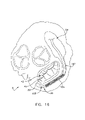
- FIGS. 17–20 illustrate still other aspects of the present invention.
- FIGS. 21–24 illustrate other aspects of the present invention.
- FIGS. 25–27 illustrate another form of the present invention
- FIGS. 28–32 illustrate the embodiment of FIGS. 25–27 in use
- FIGS. 32A–32C illustrate another aspect of the present invention
- FIGS. 32D and 32E illustrate another aspect of the present invention
- FIGS. 33 and 34 illustrate another form of the present invention
- FIGS. 35–37 illustrate the embodiment of FIGS. 33 and 34 in use
- FIGS. 37A–37C illustrate another aspect of the present invention
- FIGS. 37D and 37E illustrate another aspect of the present invention
- FIGS. 37F–37I illustrate another aspect of the present invention
- FIGS. 37J and 37K illustrate yet another aspect of the present invention
- FIG. 38 illustrates another form of the present invention
- FIGS. 39 and 40 illustrate the embodiment of FIG. 38 in use
- FIGS. 41 and 42 illustrate yet another form of the present invention.
- FIGS. 43 and 44 illustrate still another aspect of the present invention.
- the coronary sinus is the largest vein in the human heart. During a large portion of its course in the atrioventricular groove, the coronary sinus typically extends adjacent to the left atrium of the heart for a distance of approximately 5 to 10 centimeters. Significantly, for a portion of its length, e.g., typically approximately 7–9 cm, the coronary sinus extends substantially adjacent to the posterior perimeter of the mitral annulus.
- the present invention takes advantage of this consistent anatomic relationship.
- the natural curvature of the coronary sinus may be modified in the vicinity of the posterior leaflet of the mitral valve, whereby to move the posterior annulus anteriorly so as to improve leaflet coaptation and, as a result, reduce mitral regurgitation.
- the novel apparatus comprises a straight, substantially rigid elongated body, the length of the straight, substantially rigid elongated body being sized so that when the straight, substantially rigid body is positioned in the coronary sinus in the vicinity of the posterior leaflet of the mitral valve, the straight, substantially rigid elongated body will cause at least a portion of the coronary sinus to assume a substantially straight configuration adjacent to the posterior leaflet of the mitral valve, whereby to move the posterior annulus anteriorly and thereby improve leaflet coaptation.
- the straight, substantially rigid elongated body is introduced into the patient's vascular system via the jugular vein or via the left subclavian vein, passed down the superior vena cava, passed through the right atrium and then passed into the coronary sinus, where it is deployed.
- the straight, substantially rigid elongated body may be introduced into the coronary sinus through a small incision in the heart, or through some other incision into the patient's vascular system.
- the straight, substantially rigid elongated body is guided into position by (i) passing it through a pre-positioned catheter, or (ii) passing it over a pre-positioned guidewire, or (iii) passing it guide-free (e.g., on the end of a steerable delivery tool) to the surgical site.
- the novel apparatus may be left in position permanently (e.g., in the case of patients suffering from mitral regurgitation associated with heart failure) or the novel apparatus may be left in position only temporarily (e.g., in the case of patients suffering from mitral regurgitation associated with acute myocardial infarction).
- Visualization of the procedure may be obtained by fluoroscopy, echocardiography, intravascular ultrasound, angioscopy, real-time magnetic resonance imaging, etc.
- the efficacy of the procedure may be determined through echocardiography, although other imaging modalities may also be suitable.
- cardiovascular system 3 generally comprises the heart 6 , the superior vena cava 9 ( FIG. 1 ), the right subclavian vein 12 , the left subclavian vein 15 , the jugular vein 18 , and the inferior vena cava 21 .
- Superior vena cava 9 and inferior vena cava 21 communicate with the heart's right atrium 24 ( FIGS. 1 and 2 ).
- the coronary ostium 27 leads to coronary sinus 30 .
- the vascular structure turns into the vertically-descending anterior interventricular vein (“AIV”) 32 ( FIG. 1 ).
- AIV anterior interventricular vein
- mitral valve 36 comprises a posterior leaflet 39 and an anterior leaflet 42 .
- posterior leaflet 39 and anterior leaflet 42 will generally fail to properly coapt at systole, thereby leaving an intervening gap 45 which will permit regurgitation.
- system 100 which comprises one preferred embodiment of the present invention. More particularly, system 100 generally comprises a guidewire 103 , a delivery catheter 106 and a push rod 109 .
- Guidewire 103 comprises a flexible body 112 having a distal end 115 and a proximal end 118 .
- the distal end 115 of guidewire 103 preferably includes a spring tip 121 for allowing the distal end of guidewire 103 to atraumatically traverse vascular structures, i.e., while the guidewire is being passed through the vascular system of a patient.
- Delivery catheter 106 comprises a flexible body 124 having a distal end 127 and a proximal end 130 , preferably with an adjustable valve 133 attached.
- a central lumen 136 extends from distal end 127 to proximal end 130 .
- a balloon 139 may be positioned about the exterior of flexible body 124 , just proximal to distal end 127 , with an inflation lumen 142 extending between balloon 139 and an inflation fitting 145 .
- Push rod 109 comprises a flexible body 148 having a distal end 151 and a proximal end 154 .
- a straight, substantially rigid elongated body 157 which may have a variety of different lengths, is formed on flexible body 148 , proximal to distal end 151 .
- a removable proximal stiffener or handle 160 may be placed between straight, substantially rigid elongated body 157 and proximal end 154 .
- System 100 may be used as follows to reduce mitral regurgitation.
- distal end 115 of guidewire 103 is passed down the jugular vein 18 (or the left subclavian vein 15 ) of a patient, down superior vena cava 9 , through right atrium 24 of the heart, and then into coronary sinus 30 . See FIG. 4 .
- the guidewire will tend to assume the natural curved shape of the coronary sinus, due to the flexible nature of the guidewire.
- the guidewire's atraumatic spring tip 121 will help ensure minimal damage to vascular structures as guidewire 103 is maneuvered into position.
- distal end 127 of delivery catheter 106 is placed over proximal end 118 of guidewire 103 and passed down the guidewire until the distal end of the delivery catheter is positioned in coronary sinus 30 . See FIG. 5 .
- the delivery catheter will tend to assume the natural curved shape of the coronary sinus, due to the flexible nature of the delivery catheter.
- balloon 139 may be inflated so as to secure distal end 127 of delivery catheter 106 in position within coronary sinus 30 .
- push rod 109 is passed down the central lumen 136 of delivery catheter 106 .
- the push rod's straight, substantially rigid elongated body 157 is passed down central lumen 136 of delivery catheter 106 , it will force the delivery catheter to assume a straight configuration at the point where the straight, substantially rigid elongated body 157 currently resides.
- balloon 139 will hold the distal end of the delivery catheter in position within coronary sinus 30 .
- Push rod 109 is pushed down delivery catheter 106 , utilizing removable proximal stiffener 160 as needed, until the straight, substantially rigid elongated body 157 is located adjacent to the posterior annulus of mitral valve 36 . See FIG. 7 .
- the presence of the straight, substantially rigid elongated body 157 in delivery catheter 106 will cause at least a portion of coronary sinus 30 to assume a substantially straight configuration at this point, so that the posterior annulus of mitral valve 36 is forced anteriorly. This will cause the mitral valve's posterior leaflet 39 to also move anteriorly so as to improve mitral valve leaflet coaptation and thereby reduce (or completely eliminate) mitral valve regurgitation.
- the posterior annulus may be shifted anteriorly so as to achieve, or to attempt to achieve to the extent anatomically possible, leaflet-to-leaflet engagement or leaflet-to-annulus engagement (e.g., where a leaflet may be tethered due to left ventricular distortion).
- leaflet-to-leaflet engagement or leaflet-to-annulus engagement e.g., where a leaflet may be tethered due to left ventricular distortion.
- Both of these types of engagement, or targeted engagement are intended to be encompassed by the terms “improved leaflet coaptation” and/or “increased leaflet coaptation” and the like.
- standard visualization means e.g. echocardiography or fluoroscopy
- the exact position of the straight, substantially rigid elongated body 157 is adjusted so as to reduce (or completely eliminate) regurgitation in mitral valve 36 .
- the straight, substantially rigid elongated body 157 is preferably sized to be somewhat less than the length of the coronary sinus between coronary ostium 27 and AIV 32 . However, in some circumstances it may be desirable to size the straight, substantially rigid elongated body 157 so that it will extend out of the coronary sinus and into the right atrium.
- the system provides a degree of tactile feedback to the user during deployment. More particularly, substantial resistance will typically be encountered as the straight, substantially rigid elongated body 157 is pushed out of right atrium 24 and into coronary sinus 30 ; then resistance will typically drop as body 157 is moved through the coronary sinus; and then resistance will typically increase significantly again as the distal tip of body 157 comes to the far end 31 of the coronary sinus.
- tactile “sweet spot” when the straight, substantially rigid elongated body 157 is located in the coronary sinus between coronary ostium 27 and AIV 32 , and this tactile “sweet spot” can be helpful to the user in positioning the straight, substantially rigid elongated body 157 in coronary sinus 30 .
- System 100 is left in this position until it is no longer needed. In some cases this may mean that system 100 is left in position for a period of a few hours, days or weeks; in other cases system 100 may be substantially permanent. If and when system 100 is to be removed, push rod 109 is removed from delivery catheter 106 , and then delivery catheter 106 is removed from the patient.
- the straight, substantially rigid elongated body 157 is essentially force-fit into the normally curved portion of the coronary sinus adjacent to the mitral valve's posterior leaflet.
- the straight, substantially rigid elongated body will cause at least a portion of the coronary sinus to assume a substantially straight configuration adjacent to the posterior leaflet of the mitral valve. This action will in turn drive the posterior annulus of the mitral valve anteriorly, so as to improve leaflet coaptation and thereby reduce mitral regurgitation.
- the annulus of the mitral valve is effectively manipulated so that it will assume an increased radius of curvature.
- the left ventricle may also be remodeled so as to help alleviate congestive heart failure.
- the distal and proximal ends of straight, substantially rigid elongated body 157 apply a posteriorly-directed force on the walls of coronary sinus 30 (e.g., as shown with arrows P in FIG. 7 ) while the intermediate portion of straight, substantially rigid elongated body 157 applies an anteriorly-directed force on the walls of coronary sinus 30 (e.g., as shown with arrows A in FIG. 7 ).
- proximal end 130 of delivery catheter 106 may be fixed to the patient's outer skin using standard patient care methods such as adhesive tape, pursestring sutures, skin staples, etc.
- proximal end 130 of delivery catheter 106 may include a sewing cuff whereby the delivery catheter may be secured to the patient's tissue by suturing. See, for example, FIG. 8 , where a sewing cuff 166 is shown attached to the proximal end 130 of delivery catheter 106 .
- an element 169 may be provided proximal to adjustable valve 133 , whereby flexible push rod 109 may be made fast to delivery catheter 106 .
- element 169 may comprise a crimpable element to secure flexible push rod 109 to delivery catheter 106 , which is in turn secured to the patient.
- the proximal end of the assembly may be embedded under the skin of the patient, e.g., in the case of a permanent implant.
- the distal end of delivery catheter 106 can be secured in position within the coronary sinus prior to pushing push rod 109 into the delivery catheter. Such an arrangement will keep the delivery catheter in place as the push rod makes the turn within the right atrium and enters the coronary sinus. In the absence of such anchoring, the push rod may drive the delivery catheter down the inferior vena cava 21 .
- the delivery catheter By securing the distal end of delivery catheter 106 to the walls of coronary sinus 30 , the delivery catheter can be stabilized against diversion down the inferior vena cava 21 when the straight, substantially rigid elongate body 157 encounters initial resistance to making the turn into the coronary sinus.
- the balloon 139 is one way of accomplishing such anchoring. However, it is also possible to utilize other types of securing mechanisms to anchor the distal end 127 of delivery catheter 106 in position within coronary sinus 30 , e.g., spring clips, ribs, etc.
- the distal end 151 of push rod 109 may itself be provided with a distal anchor, e.g., such as the distal anchor 172 shown in FIG. 9 .
- FIG. 9A there is shown a support catheter 173 which is formed out of a more rigid material than delivery catheter 106 .
- Support catheter 173 is constructed so that its distal end 174 can be positioned in coronary ostium 27 and then its sidewall 174 A can support delivery catheter 106 adjacent to inferior vena cava 21 when push rod 109 is passed down delivery catheter 106 , whereby to prevent delivery catheter 106 from diverting down inferior vena cava 21 .
- FIG. 9A also shows an introducer catheter 174 B at the entrance to jugular vein 18 .
- the straight, substantially rigid elongated body 157 will distort the natural configuration of the coronary sinus so that it will assume a substantially straight configuration. While this action induces the desired valve remodeling, it can also induce a significant stress on the walls of the coronary sinus, particularly at the distal and proximal ends of the straight, substantially rigid elongated body 157 , where stress will be concentrated. To this end, the construction of the straight, substantially rigid elongated body 157 may be modified somewhat so as to better distribute this stress. More particularly, and looking next at FIG.
- the distal and proximal ends of straight, substantially rigid elongated body 157 may include relatively flexible portions 175 to help better distribute the stress exerted on the walls of the coronary sinus. Additionally, and/or alternatively, any taper applied to the distal and proximal ends of straight, substantially rigid elongated body 157 may be elongated, e.g., such as shown at 178 in FIG. 11 , so as to better distribute the stress imposed on the walls of the coronary sinus.
- push rod 109 is described as being inserted to the surgical site through the delivery catheter 106 and remaining within delivery catheter 106 while at the surgical site and, when push rod 109 is to be removed, removing push rod 109 and then delivery catheter 106 . However, if desired, once push rod 109 has been deployed at the surgical site, delivery catheter 106 may then be removed, leaving just push rod 109 at the surgical site. See, for example, FIG. 11A .
- push rod 109 It is also possible to advance push rod 109 directly to the surgical site without passing it through a delivery catheter; in this case push rod 109 would be advanced on its own through the intervening vascular structure until it is deployed in coronary sinus 30 .
- system 181 which comprises another preferred embodiment of the present invention. More particularly, system 181 generally comprises the guidewire 103 , a straight, substantially rigid elongated body 184 and a push cannula 187 .
- Guidewire 103 is as previously described.
- Straight, substantially rigid elongated body 184 which may have a variety of different lengths, comprises a distal end 188 and a proximal end 190 .
- a central lumen 193 extends between distal end 188 and proximal end 190 . Central lumen 193 accommodates guidewire 103 .
- Push cannula 187 comprises a distal end 194 and a proximal end 196 .
- a central lumen 199 extends between distal end 194 and proximal end 196 .
- Central lumen 199 accommodates guidewire 103 .
- elongated body 184 and push cannula 187 may be mounted on guidewire 103 , and push cannula 187 may be used to push elongated body 184 down guidewire 103 . See FIG. 13 .
- System 181 may be used as follows to reduce mitral regurgitation.
- distal end 115 of guidewire 103 is passed down jugular vein 18 (or the left subclavian vein 15 ) of a patient, down superior vena cava 9 , through right atrium 24 of the heart, and into coronary sinus 30 ( FIG. 14 ).
- the guidewire will tend to assume the natural curved shape of the coronary sinus, due to the flexible nature of the guidewire.
- the guidewire's atraumatic spring tip 121 will help minimize damage to vascular structures as the guidewire is advanced into position.
- distal end 188 of straight, substantially rigid elongated body 184 is placed over proximal end 118 of guidewire 103 and passed a short distance down the guidewire. Then the distal end 194 of push cannula 187 is placed over proximal end 118 of guidewire 103 , and then push cannula 187 is advanced down the guidewire. As push cannula 187 is advanced down the guidewire, its distal end 194 pushes the straight, substantially rigid elongated body 184 ahead of it. See FIG. 15 .
- the posterior mitral valve leaflet will cause the posterior mitral valve leaflet to also move anteriorly so as to improve leaflet coaptation and thereby reduce (or completely eliminate) mitral valve regurgitation.
- standard visualization means e.g. echocardiography or fluoroscopy
- the exact position of the straight, substantially rigid elongated body may be adjusted so as to reduce (or completely eliminate) regurgitation in the mitral valve.
- the push cannula 187 may be provided with a releasably attachable interface (e.g., a grasper) so that it may releasably secure the proximal end 190 of the straight, substantially rigid elongated body 184 .
- a releasably attachable interface e.g., a grasper
- Such a feature will permit the straight, substantially rigid elongated body to be pulled backward within the coronary sinus, either for positioning or removal purposes.
- elongated body 184 is to be left within the body for a substantial period of time, it is possible to leave the apparatus in the position shown in FIG. 16 , i.e., with elongated body 184 fit over guidewire 103 and at the end of push cannula 187 .
- guidewire 103 and/or push cannula 187 may be removed, leaving just elongated body 184 deployed at the surgical site ( FIG. 16A ).
- Elongated body 157 and/or elongated body 184 may have any of a variety of non-straight shapes along its length.
- the elongated body may be wavy, spiraled, or curved along all or a portion of its length.
- elongated body 157 and/or 184 may have a curved configuration so as to invert the natural curvature of the coronary sinus, i.e., so that it is bowed towards the anterior annulus.
- the elongated body may have a compound shape along its length, e.g., it may have a sort of “w” shape, with the center of the “w” being directed towards the anterior annulus. See, for example, FIG.
- FIG. 17 which shows a push rod 109 having an elongated body 157 with a “w” type of shape
- FIG. 18 which shows an elongated body 184 with a “w” type of shape.
- FIGS. 19 and 20 show a “w” shaped elongated body 184 being advanced down guidewire 103 ( FIG. 19 ) to a position adjacent to mitral valve 36 ( FIG. 20 ), whereby to reduce mitral regurgitation.
- Any of the aforementioned elongated body shapes, or other alternative shapes, may effect the anterior displacement of the posterior annulus that results in reduction of the mitral valve regurgitation.
- delivery catheter 106 is preferably sized so as to have a diameter less than the diameter of coronary sinus 30 , so that blood may flow about the perimeter of delivery catheter 106 when delivery catheter 106 is disposed in coronary sinus 30 .
- delivery catheter 106 may be provided with one or more longitudinally-extending surface grooves SG so as to facilitate blood flow past the perimeter of delivery catheter 106 .
- elongated body 184 is preferably sized so as to have a diameter less that the diameter of coronary sinus 30 , so that blood may flow about the perimeter of elongated body 184 when elongated body 184 is disposed in coronary sinus 30 .
- elongated body 184 may be provided with one or more longitudinally-extending surface grooves SG so as to facilitate blood flow past the perimeter of elongated body 184 .
- elongated bodies 157 and 184 are shown completely formed prior to their deployment in the patient. However, it is also possible to form elongated body 157 and/or elongated body 184 in situ from a plurality of smaller elements.
- push rod 109 for use with guidewire 103 and delivery catheter 106 .
- push rod 109 comprises flexible body 148 and a plurality of substantially rigid elongated elements 157 A, 157 B, 157 C, etc. which collectively form the complete elongated body 157 .
- the distalmost elongated element 157 A is fixed to flexible body 148 while the remaining elongated elements 157 B, 157 C, 157 D, etc. are free to slide on flexible body 148 .
- elongated elements 157 A, 157 B, 157 C, etc. preferably include connectors C for permitting one elongated element to be secured to a neighboring elongated body.
- the connectors C shown in FIG. 25 comprise male and female screw type connectors; however, other types of connectors may also be used.
- elongated body 157 By assembling the elongated body 157 in situ using a plurality of elongated elements 157 A, 157 B, 157 C, etc., it is possible to create an elongated body 157 which is perfectly sized to the needs of the patient.
- the push rod 109 shown in FIGS. 25–27 may be used as follows. First, guidewire 103 is passed down to the coronary sinus ( FIG. 28 ). Then delivery catheter 106 is passed down guidewire 103 and into the coronary sinus ( FIGS. 28 and 29 ). Then the guidewire 103 is withdrawn from the surgical site and replaced by the push rod's flexible body 148 with elongated element 157 A attached ( FIG. 30 ). Next, a plurality of elongated elements 157 B, 157 C, 157 D, etc. are slid down flexible body 148 ( FIG. 31 ) and secured to elongated element 157 A (and any preceding elongated element). As many elongated elements 157 A, 157 B, 157 C, etc. are used as is necessary to effect the desired leaflet coaptation ( FIG. 32 ).
- elongated body 157 is formed by a plurality of elongated elements 157 A, 157 B, 157 C, etc. which collectively form the complete elongated body 157 .
- the distalmost elongated element 157 A is fixed to flexible body 148 while the remaining elongated elements 157 A, 157 B, 157 C, etc. are free to slide on flexible body 148 .
- elongated body 157 may be formed in situ by moving elongated elements 157 A, 157 B, 157 C, etc.
- elongated element 157 A acting as a distal stop, and then keeping elongated elements 157 A, 157 B, 157 C, etc. biased distally with a holding mechanism, e.g., a crimp CR.
- a holding mechanism e.g., a crimp CR.
- elongated elements 157 A, 157 B, 157 C, etc. are shown configured so as to form a substantially straight elongated body 157 .
- elongated elements 157 A, 157 B, 157 C, etc. could have alternative configurations so as to form other body shapes.
- elongated elements 157 A, 157 B, 157 C, etc. are shown forming a curved elongated body 157
- FIG. 32E elongated elements 157 A, 157 B, 157 C, etc. are shown forming a composite curved-and-straight elongated body 157 .
- elongated elements 157 A, 157 B, 157 C, etc may be formed by elongated elements 157 A, 157 B, 157 C, etc.
- the shapes of elongated body 157 may be established either by (1) forming elongated elements 157 A, 157 B, 157 C, etc. so that they have only one possible way of being assembled together, or (2) by forming elongated elements 157 A, 157 B, 157 C, etc. so that they have multiple ways of being assembled together.
- one possible way to vary the final configuration of elongated body 157 is by individually rotating various ones of elongated elements 157 A, 157 B, 157 C, etc., e.g., such as is shown in FIGS. 32D and 32E .
- FIGS. 33 and 34 there is shown an alternative form of elongated body 184 which comprises a plurality of substantially rigid elongated elements 184 A, 184 B, 184 C, etc. which collectively form the complete elongated body 184 .
- elongated elements 184 A, 184 B, 184 C, etc. preferably include connectors C for permitting one elongated element to be secured to a neighboring elongated element.
- the connectors C shown in FIG. 25 comprise male and female screw type connectors; however, other types of connectors may also be used.
- the elongated body 184 shown in FIGS. 33 and 34 may be used as follows. First, guidewire 103 is passed down coronary sinus 30 ( FIG. 35 ). Then push cannula 187 is used to push a plurality of elongated elements 184 A, 184 B, 184 C, etc. down guidewire 103 and into the coronary sinus ( FIGS. 36 and 37 ). As many elongated elements 184 A, 184 B, 184 C, etc. are used as is necessary to effect the desired leaflet coaptation ( FIG. 37 ).
- FIGS. 37A–37C there is shown another form of elongated body 184 . More particularly, with this form of elongated body, the elongated body 184 is formed by a plurality of elongated elements 184 A, 184 B, 184 C, etc. which collectively form the complete elongated body 184 . Preferably, all of the elongated elements 184 A, 184 B, 184 C, etc. are free to slide on guidewire 103 . With this version of the invention, elongated body 184 may be formed in situ by moving elongated elements 184 A, 184 B, 184 C, etc. distally and then drawing them tightly together, e.g., such as by using a cinching system such as that shown in FIG. 37C and comprising a distal member DM and a crimp CR.
- a cinching system such as that shown in FIG. 37C and comprising a distal member DM and a crimp CR
- elongated element 184 A, 184 B, 184 C, etc. are shown configured so as to form a substantially straight elongated body 184 .
- elongated elements 184 A, 184 B, 184 C, etc. could have alternative configurations so as to form other body shapes.
- FIG. 37D elongated elements 184 A, 184 B, 184 C, etc. are shown forming a curved elongated body 184
- FIG. 37E elongated elements 184 A, 184 B, 184 C, etc.
- elongated body 184 is shown forming a composite curved-and-straight elongated body 184 . It will be appreciated that still other shapes may be formed by elongated elements 184 A, 184 B, 184 C, etc. In this respect it will be appreciated that the shapes of elongated body 184 may be established either by (1) forming elongated elements 184 A, 184 B, 184 C, etc. so that they have only one possible way of being assembled together, or (2) by forming elongated elements 184 A, 184 B, 184 C, etc. so that they have multiple ways of being assembled together.
- one possible way to vary the final configuration of elongated body 184 is by individually rotating various ones of elongated elements 184 A, 184 B, 184 C, etc., e.g., such as is shown in FIGS. 37D and 37E .
- straightening device 109 A which is another form of push rod 109
- straightening apparatus 109 A has an elongated body 157 formed by a plurality of elongated elements 157 A, 157 B, 157 C, etc.
- Each of the elongated elements 157 A, 157 B, 157 C, etc. is attached to flexible body 148 and is separated from adjacent elongated elements by a gap G.
- gaps G By orienting gaps G radially away from mitral valve 36 ( FIG.
- straightening apparatus 109 A will be able to curve as required so as to follow the natural curvature of the coronary sinus, e.g., during insertion of push rod 109 into coronary sinus 30 .
- gaps G will be closed and straightening apparatus 109 A will be straightened, whereby to apply an anteriorly-directed force to the posterior annulus of mitral valve 36 and reduce mitral regurgitation.
- an internal member IM has a plurality of slots SI and an external member EM has a plurality of slots SE.
- Internal member IM is concentrically received within external member EM.
- internal member IM and external member EM may be curved as required so as to follow the natural curvature of the coronary sinus, e.g. during insertion of the members into the coronary sinus.
- internal member IM and external member EM will be straightened, whereby to apply an anteriorly-directed force to the posterior annulus of the mitral valve and reduce mitral regurgitation.
- elongated body 157 of push rod 109 ( FIG. 3 ) with an inflatable construction. More particularly, and looking next at FIG. 38 , there is shown a push rod 109 having an inflatable elongated body 157 in the form of a balloon B.
- the push rod's flexible body 148 includes an inflation lumen L which communicates with the interior of balloon B, whereby fluid may be supplied to the interior of the balloon so as to inflate the balloon.
- the balloon B is constructed so that it has a flexible configuration when it is in a deflated condition and an elongated, straight configuration when it is in an inflated condition.
- the push rod 109 of FIG. 38 may be used as follows. First, guidewire 103 is advanced into the coronary sinus 30 ( FIG. 4 ). Then delivery cannula 106 is advanced over guidewire 103 until the distal end of the delivery cannula is in coronary sinus 30 ( FIG. 5 ). Next, guidewire 103 is withdrawn ( FIG. 6 ). Then push rod 109 , with elongated body 157 in a deflated condition, is advanced along the interior of delivery cannula 106 so that balloon B is adjacent to the mitral valve ( FIG. 39 ). Then balloon B is inflated, using inflation lumen L, so that elongated body assumes its elongated, straightening configuration ( FIG. 40 ). As this occurs, the posterior annulus of the mitral valve is compressed anteriorly, so as to reduce mitral regurgitation.
- an inflatable elongated body 157 of push rod 109 with other configurations.
- inflatable body 157 may comprise a distal portion 157 ′ and a proximal portion 157 ′′, with the distal and proximal portions being in a sliding, piston-like relationship.
- fluid may be supplied to the combined interiors of the distal and proximal portions, so as to force the two elements apart relative to one another.
- the flexible body 148 may comprise an electrical lead for an implantable bi-ventricular pacing device and/or an electrical lead for an implantable cardio defibrillator device, etc.
- the distal end of flexible body 148 would be elongated somewhat and would not reside within the coronary sinus; rather, it would be positioned within the tissue which is to receive the electrical stimulus while elongated body 157 is positioned adjacent to the mitral valve.
- Such a construction would allow the bi-ventricular pacing device and/or the implantable cardio defibrillator device to work in conjunction with elongated body 157 to reduce mitral regurgitation.
- hydraulic energy employed to enlarge inflatable body 157 may be substituted by a mechanical energy transformer such as a lead screw mechanism or an electromechanical solenoid.
- the guidewire 103 over which elongated body 184 is deployed may also be in the form of an electrical lead for an implantable bi-ventricular pacing device and/or an electrical lead for an implantable cardio defibrillator device, etc.
- the distal end of the wire will be positioned within the tissue which is to receive the electrical stimulus while elongated body 184 is positioned adjacent to the mitral valve.
- Such a construction would allow the implantable bi-ventricular pacing device and/or the implantable cardio defibrillator device to work in conjunction with elongated body 157 to reduce mitral regurgitation.
- an elongated shape memory alloy body SMA which is configured to be substantially flexible at a temperature T 1 and substantially rigid and in a straight configuration at another temperature T 2 , where temperature T 2 is normal body temperature.
- body SMA is brought to temperature T 1 , so that it may be inserted more easily into the natural curvature of the coronary sinus, e.g., during insertion of body SMA into the coronary sinus ( FIG. 43 ).
- body SMA when body SMA thereafter transitions to temperature T 2 , body SMA will assume its straight configuration ( FIG.
- body SMA may be other than straight (i.e., “w” shape, etc.) to best displace the posterior annulus anteriorly.
- the elongated body may be flexible along at least a portion of its length. Regional flexibility and regional stiffness may allow for straightening of select locations of the coronary sinus and corresponding locations of the posterior mitral annulus. This can cause regions of the mitral annulus to move anteriorly, thus causing regional improvements in leaflet coaptation.
- the elongated body may be formed by two end segments connected together by a filament: by anchoring the two end segments relative to the anatomy and pulling the filament taught, the naturally curved wall of the coronary sinus can be straightened, whereby to move the posterior mitral annulus anteriorly and thereby reduce mitral regurgitation.
- the present invention may also be used to alter the shape of other cardiac tissues, including but not limited to the left ventricle, for other uses, including the treatment of cardiac dysfunction.
Abstract
Description
Claims (19)
Priority Applications (15)
| Application Number | Priority Date | Filing Date | Title |
|---|---|---|---|
| US10/112,354 US7186264B2 (en) | 2001-03-29 | 2002-03-29 | Method and apparatus for improving mitral valve function |
| PCT/US2002/025890 WO2003015611A2 (en) | 2001-08-14 | 2002-08-14 | Method and apparatus for improving mitral valve function |
| AU2002332537A AU2002332537A1 (en) | 2001-08-14 | 2002-08-14 | Method and apparatus for improving mitral valve function |
| US10/218,649 US20030078654A1 (en) | 2001-08-14 | 2002-08-14 | Method and apparatus for improving mitral valve function |
| US10/280,401 US7052487B2 (en) | 2001-10-26 | 2002-10-25 | Method and apparatus for reducing mitral regurgitation |
| EP03707367A EP1471858A4 (en) | 2002-01-14 | 2003-01-14 | Method and apparatus for reducing mitral regurgitation |
| PCT/US2003/000971 WO2003059198A2 (en) | 2002-01-14 | 2003-01-14 | Method and apparatus for reducing mitral regurgitation |
| US10/342,034 US7241310B2 (en) | 2002-01-14 | 2003-01-14 | Method and apparatus for reducing mitral regurgitation |
| AU2003209219A AU2003209219A1 (en) | 2002-01-14 | 2003-01-14 | Method and apparatus for reducing mitral regurgitation |
| CA002472482A CA2472482A1 (en) | 2002-01-14 | 2003-01-14 | Method and apparatus for reducing mitral regurgitation |
| US10/446,470 US7125420B2 (en) | 2002-02-05 | 2003-05-27 | Method and apparatus for improving mitral valve function |
| US11/371,642 US20060229717A1 (en) | 2001-10-26 | 2006-03-09 | Method and apparatus for reducing mitral regurgitation |
| US11/582,157 US20070156235A1 (en) | 2002-02-05 | 2006-10-17 | Method and apparatus for improving mitral valve function |
| US11/714,710 US20070213814A1 (en) | 2001-03-29 | 2007-03-06 | Method and apparatus for improving mitral valve function |
| US11/818,991 US20080103590A1 (en) | 2002-01-14 | 2007-06-15 | Method and apparatus for reducing mitral regurgitation |
Applications Claiming Priority (9)
| Application Number | Priority Date | Filing Date | Title |
|---|---|---|---|
| US27997301P | 2001-03-29 | 2001-03-29 | |
| US27997401P | 2001-03-29 | 2001-03-29 | |
| US28003801P | 2001-03-30 | 2001-03-30 | |
| US28382001P | 2001-04-13 | 2001-04-13 | |
| US31221701P | 2001-08-14 | 2001-08-14 | |
| US33948101P | 2001-10-26 | 2001-10-26 | |
| US34842402P | 2002-01-14 | 2002-01-14 | |
| US10/068,264 US6656221B2 (en) | 2001-02-05 | 2002-02-05 | Method and apparatus for improving mitral valve function |
| US10/112,354 US7186264B2 (en) | 2001-03-29 | 2002-03-29 | Method and apparatus for improving mitral valve function |
Related Parent Applications (2)
| Application Number | Title | Priority Date | Filing Date |
|---|---|---|---|
| US10/068,264 Continuation-In-Part US6656221B2 (en) | 2001-02-05 | 2002-02-05 | Method and apparatus for improving mitral valve function |
| US10/218,649 Continuation-In-Part US20030078654A1 (en) | 2001-08-14 | 2002-08-14 | Method and apparatus for improving mitral valve function |
Related Child Applications (6)
| Application Number | Title | Priority Date | Filing Date |
|---|---|---|---|
| US10/068,264 Continuation-In-Part US6656221B2 (en) | 2001-02-05 | 2002-02-05 | Method and apparatus for improving mitral valve function |
| US10/218,649 Continuation-In-Part US20030078654A1 (en) | 2001-08-14 | 2002-08-14 | Method and apparatus for improving mitral valve function |
| US10/280,401 Continuation-In-Part US7052487B2 (en) | 2001-10-26 | 2002-10-25 | Method and apparatus for reducing mitral regurgitation |
| US10/342,034 Continuation-In-Part US7241310B2 (en) | 2002-01-14 | 2003-01-14 | Method and apparatus for reducing mitral regurgitation |
| US10/446,470 Continuation-In-Part US7125420B2 (en) | 2002-02-05 | 2003-05-27 | Method and apparatus for improving mitral valve function |
| US11/714,710 Continuation US20070213814A1 (en) | 2001-03-29 | 2007-03-06 | Method and apparatus for improving mitral valve function |
Publications (2)
| Publication Number | Publication Date |
|---|---|
| US20020183838A1 US20020183838A1 (en) | 2002-12-05 |
| US7186264B2 true US7186264B2 (en) | 2007-03-06 |
Family
ID=27535793
Family Applications (2)
| Application Number | Title | Priority Date | Filing Date |
|---|---|---|---|
| US10/112,354 Expired - Fee Related US7186264B2 (en) | 2001-03-29 | 2002-03-29 | Method and apparatus for improving mitral valve function |
| US11/714,710 Abandoned US20070213814A1 (en) | 2001-03-29 | 2007-03-06 | Method and apparatus for improving mitral valve function |
Family Applications After (1)
| Application Number | Title | Priority Date | Filing Date |
|---|---|---|---|
| US11/714,710 Abandoned US20070213814A1 (en) | 2001-03-29 | 2007-03-06 | Method and apparatus for improving mitral valve function |
Country Status (3)
| Country | Link |
|---|---|
| US (2) | US7186264B2 (en) |
| AU (1) | AU2002332537A1 (en) |
| WO (1) | WO2003015611A2 (en) |
Cited By (138)
| Publication number | Priority date | Publication date | Assignee | Title |
|---|---|---|---|---|
| US20040102840A1 (en) * | 1999-06-30 | 2004-05-27 | Solem Jan Otto | Method and device for treatment of mitral insufficiency |
| US20040133274A1 (en) * | 2002-11-15 | 2004-07-08 | Webler William E. | Cord locking mechanism for use in small systems |
| US20040193191A1 (en) * | 2003-02-06 | 2004-09-30 | Guided Delivery Systems, Inc. | Devices and methods for heart valve repair |
| US20040243227A1 (en) * | 2002-06-13 | 2004-12-02 | Guided Delivery Systems, Inc. | Delivery devices and methods for heart valve repair |
| US20050070844A1 (en) * | 2003-09-30 | 2005-03-31 | Mina Chow | Deflectable catheter assembly and method of making same |
| US20050107812A1 (en) * | 2002-06-13 | 2005-05-19 | Guided Delivery Systems, Inc. | Delivery devices and methods for heart valve repair |
| US20050273138A1 (en) * | 2003-12-19 | 2005-12-08 | Guided Delivery Systems, Inc. | Devices and methods for anchoring tissue |
| US20060020333A1 (en) * | 2004-05-05 | 2006-01-26 | Lashinski Randall T | Method of in situ formation of translumenally deployable heart valve support |
| US20060030885A1 (en) * | 2002-10-15 | 2006-02-09 | Hyde Gregory M | Apparatuses and methods for heart valve repair |
| US20060136053A1 (en) * | 2003-05-27 | 2006-06-22 | Rourke Jonathan M | Method and apparatus for improving mitral valve function |
| US20060241656A1 (en) * | 2002-06-13 | 2006-10-26 | Starksen Niel F | Delivery devices and methods for heart valve repair |
| US20060247672A1 (en) * | 2005-04-27 | 2006-11-02 | Vidlund Robert M | Devices and methods for pericardial access |
| US20060281968A1 (en) * | 2005-06-07 | 2006-12-14 | Duran Carlos M | System, including method and apparatus for percutaneous endovascular treatment of functional mitral valve insufficiency |
| US20070005133A1 (en) * | 2005-06-07 | 2007-01-04 | Lashinski Randall T | Stentless aortic valve replacement with high radial strength |
| US20070156235A1 (en) * | 2002-02-05 | 2007-07-05 | Jonathan Rourke | Method and apparatus for improving mitral valve function |
| US20070213814A1 (en) * | 2001-03-29 | 2007-09-13 | Liddicoat John R | Method and apparatus for improving mitral valve function |
| US20070213758A1 (en) * | 2003-05-27 | 2007-09-13 | Rourke Jonathan M | Method and apparatus for improving mitral valve function |
| US20070213812A1 (en) * | 2002-11-15 | 2007-09-13 | Webler William E | Apparatuses and methods for delivering/deploying a medical device in a vessel |
| US20080015688A1 (en) * | 2004-06-29 | 2008-01-17 | Micardia Corporation | Adjustable multi-segment cardiac valve implant with selective dimensional adjustment |
| US20080045977A1 (en) * | 2002-06-13 | 2008-02-21 | John To | Methods and devices for termination |
| US20080177382A1 (en) * | 2002-11-15 | 2008-07-24 | Gregory Matthew Hyde | Apparatus and methods for heart valve repair |
| US20080200898A1 (en) * | 2006-10-19 | 2008-08-21 | Lashinski Randall T | Catheter guidance through a calcified aortic valve |
| US20080200980A1 (en) * | 2006-10-19 | 2008-08-21 | Kevin Robin | Profile reduction of valve implant |
| US20080234728A1 (en) * | 2002-06-13 | 2008-09-25 | Guided Delivery Systems, Inc. | Devices and methods for heart valve repair |
| US20080287951A1 (en) * | 2007-03-22 | 2008-11-20 | Stoneburner James D | Segmented intramedullary structure |
| US20090088836A1 (en) * | 2007-08-23 | 2009-04-02 | Direct Flow Medical, Inc. | Translumenally implantable heart valve with formed in place support |
| US20090105729A1 (en) * | 2007-10-18 | 2009-04-23 | John Zentgraf | Minimally invasive repair of a valve leaflet in a beating heart |
| US20090222081A1 (en) * | 2008-01-24 | 2009-09-03 | Coherex Medical, Inc. | Methods and apparatus for reducing valve prolapse |
| US20100010623A1 (en) * | 2004-04-23 | 2010-01-14 | Direct Flow Medical, Inc. | Percutaneous heart valve with stentless support |
| US7666224B2 (en) | 2002-11-12 | 2010-02-23 | Edwards Lifesciences Llc | Devices and methods for heart valve treatment |
| US7678145B2 (en) | 2002-01-09 | 2010-03-16 | Edwards Lifesciences Llc | Devices and methods for heart valve treatment |
| WO2010051029A1 (en) * | 2008-10-29 | 2010-05-06 | Viacor, Inc. | Method and apparatus for improving mitral valve function |
| US20100145341A1 (en) * | 2008-12-04 | 2010-06-10 | Ranck Roger S | Trocar-tipped drill bit |
| US20100174297A1 (en) * | 2005-01-21 | 2010-07-08 | Giovanni Speziali | Thorascopic Heart Valve Repair Method and Apparatus |
| US20100280602A1 (en) * | 2003-02-03 | 2010-11-04 | Cardiac Dimensions, Inc. | Mitral Valve Device Using Conditioned Shape Memory Alloy |
| US7883539B2 (en) | 1997-01-02 | 2011-02-08 | Edwards Lifesciences Llc | Heart wall tension reduction apparatus and method |
| US20110166649A1 (en) * | 2008-06-16 | 2011-07-07 | Valtech Cardio Ltd. | Annuloplasty devices and methods of deliver therefor |
| US7981152B1 (en) | 2004-12-10 | 2011-07-19 | Advanced Cardiovascular Systems, Inc. | Vascular delivery system for accessing and delivering devices into coronary sinus and other vascular sites |
| US20110184512A1 (en) * | 2002-11-15 | 2011-07-28 | Webler William E | Valve aptation assist device |
| US8398672B2 (en) | 2003-11-12 | 2013-03-19 | Nitinol Devices And Components, Inc. | Method for anchoring a medical device |
| US20130116780A1 (en) * | 2011-11-04 | 2013-05-09 | Valtech Cardio, Ltd. | Implant having multiple rotational assemblies |
| US8926695B2 (en) | 2006-12-05 | 2015-01-06 | Valtech Cardio, Ltd. | Segmented ring placement |
| US9034032B2 (en) | 2011-10-19 | 2015-05-19 | Twelve, Inc. | Prosthetic heart valve devices, prosthetic mitral valves and associated systems and methods |
| US9044221B2 (en) | 2010-12-29 | 2015-06-02 | Neochord, Inc. | Exchangeable system for minimally invasive beating heart repair of heart valve leaflets |
| US9119719B2 (en) | 2009-05-07 | 2015-09-01 | Valtech Cardio, Ltd. | Annuloplasty ring with intra-ring anchoring |
| US9125740B2 (en) | 2011-06-21 | 2015-09-08 | Twelve, Inc. | Prosthetic heart valve devices and associated systems and methods |
| US9149602B2 (en) | 2005-04-22 | 2015-10-06 | Advanced Cardiovascular Systems, Inc. | Dual needle delivery system |
| US9414921B2 (en) | 2009-10-29 | 2016-08-16 | Valtech Cardio, Ltd. | Tissue anchor for annuloplasty device |
| US9421098B2 (en) | 2010-12-23 | 2016-08-23 | Twelve, Inc. | System for mitral valve repair and replacement |
| US9474606B2 (en) | 2009-05-04 | 2016-10-25 | Valtech Cardio, Ltd. | Over-wire implant contraction methods |
| US9526613B2 (en) | 2005-03-17 | 2016-12-27 | Valtech Cardio Ltd. | Mitral valve treatment techniques |
| US9579198B2 (en) | 2012-03-01 | 2017-02-28 | Twelve, Inc. | Hydraulic delivery systems for prosthetic heart valve devices and associated methods |
| US9597004B2 (en) | 2014-10-31 | 2017-03-21 | Irhythm Technologies, Inc. | Wearable monitor |
| US9610162B2 (en) | 2013-12-26 | 2017-04-04 | Valtech Cardio, Ltd. | Implantation of flexible implant |
| US9622861B2 (en) | 2009-12-02 | 2017-04-18 | Valtech Cardio, Ltd. | Tool for actuating an adjusting mechanism |
| US9649211B2 (en) | 2009-11-04 | 2017-05-16 | Confluent Medical Technologies, Inc. | Alternating circumferential bridge stent design and methods for use thereof |
| US9655722B2 (en) | 2011-10-19 | 2017-05-23 | Twelve, Inc. | Prosthetic heart valve devices, prosthetic mitral valves and associated systems and methods |
| US9662209B2 (en) | 2008-12-22 | 2017-05-30 | Valtech Cardio, Ltd. | Contractible annuloplasty structures |
| US9706996B2 (en) | 2008-02-06 | 2017-07-18 | Ancora Heart, Inc. | Multi-window guide tunnel |
| US9713530B2 (en) | 2008-12-22 | 2017-07-25 | Valtech Cardio, Ltd. | Adjustable annuloplasty devices and adjustment mechanisms therefor |
| US9724192B2 (en) | 2011-11-08 | 2017-08-08 | Valtech Cardio, Ltd. | Controlled steering functionality for implant-delivery tool |
| US9730793B2 (en) | 2012-12-06 | 2017-08-15 | Valtech Cardio, Ltd. | Techniques for guide-wire based advancement of a tool |
| US9763780B2 (en) | 2011-10-19 | 2017-09-19 | Twelve, Inc. | Devices, systems and methods for heart valve replacement |
| US9861350B2 (en) | 2010-09-03 | 2018-01-09 | Ancora Heart, Inc. | Devices and methods for anchoring tissue |
| US9883943B2 (en) | 2006-12-05 | 2018-02-06 | Valtech Cardio, Ltd. | Implantation of repair devices in the heart |
| US9901443B2 (en) | 2011-10-19 | 2018-02-27 | Twelve, Inc. | Prosthetic heart valve devices, prosthetic mitral valves and associated systems and methods |
| US9949829B2 (en) | 2002-06-13 | 2018-04-24 | Ancora Heart, Inc. | Delivery devices and methods for heart valve repair |
| US9949828B2 (en) | 2012-10-23 | 2018-04-24 | Valtech Cardio, Ltd. | Controlled steering functionality for implant-delivery tool |
| US9968454B2 (en) | 2009-10-29 | 2018-05-15 | Valtech Cardio, Ltd. | Techniques for guide-wire based advancement of artificial chordae |
| US9968452B2 (en) | 2009-05-04 | 2018-05-15 | Valtech Cardio, Ltd. | Annuloplasty ring delivery cathethers |
| US10092427B2 (en) | 2009-11-04 | 2018-10-09 | Confluent Medical Technologies, Inc. | Alternating circumferential bridge stent design and methods for use thereof |
| US10098737B2 (en) | 2009-10-29 | 2018-10-16 | Valtech Cardio, Ltd. | Tissue anchor for annuloplasty device |
| US10111747B2 (en) | 2013-05-20 | 2018-10-30 | Twelve, Inc. | Implantable heart valve devices, mitral valve repair devices and associated systems and methods |
| US10195030B2 (en) | 2014-10-14 | 2019-02-05 | Valtech Cardio, Ltd. | Leaflet-restraining techniques |
| US10226342B2 (en) | 2016-07-08 | 2019-03-12 | Valtech Cardio, Ltd. | Adjustable annuloplasty device with alternating peaks and troughs |
| US10231831B2 (en) | 2009-12-08 | 2019-03-19 | Cardiovalve Ltd. | Folding ring implant for heart valve |
| US10238490B2 (en) | 2015-08-21 | 2019-03-26 | Twelve, Inc. | Implant heart valve devices, mitral valve repair devices and associated systems and methods |
| US10265172B2 (en) | 2016-04-29 | 2019-04-23 | Medtronic Vascular, Inc. | Prosthetic heart valve devices with tethered anchors and associated systems and methods |
| US10271754B2 (en) | 2013-01-24 | 2019-04-30 | Irhythm Technologies, Inc. | Physiological monitoring device |
| US10299793B2 (en) | 2013-10-23 | 2019-05-28 | Valtech Cardio, Ltd. | Anchor magazine |
| US10350068B2 (en) | 2009-02-17 | 2019-07-16 | Valtech Cardio, Ltd. | Actively-engageable movement-restriction mechanism for use with an annuloplasty structure |
| US10376266B2 (en) | 2012-10-23 | 2019-08-13 | Valtech Cardio, Ltd. | Percutaneous tissue anchor techniques |
| US10405799B2 (en) | 2010-05-12 | 2019-09-10 | Irhythm Technologies, Inc. | Device features and design elements for long-term adhesion |
| US10433961B2 (en) | 2017-04-18 | 2019-10-08 | Twelve, Inc. | Delivery systems with tethers for prosthetic heart valve devices and associated methods |
| US10449333B2 (en) | 2013-03-14 | 2019-10-22 | Valtech Cardio, Ltd. | Guidewire feeder |
| US10470882B2 (en) | 2008-12-22 | 2019-11-12 | Valtech Cardio, Ltd. | Closure element for use with annuloplasty structure |
| US10517719B2 (en) | 2008-12-22 | 2019-12-31 | Valtech Cardio, Ltd. | Implantation of repair devices in the heart |
| US10575950B2 (en) | 2017-04-18 | 2020-03-03 | Twelve, Inc. | Hydraulic systems for delivering prosthetic heart valve devices and associated methods |
| US10588620B2 (en) | 2018-03-23 | 2020-03-17 | Neochord, Inc. | Device for suture attachment for minimally invasive heart valve repair |
| US10646338B2 (en) | 2017-06-02 | 2020-05-12 | Twelve, Inc. | Delivery systems with telescoping capsules for deploying prosthetic heart valve devices and associated methods |
| US10682232B2 (en) | 2013-03-15 | 2020-06-16 | Edwards Lifesciences Corporation | Translation catheters, systems, and methods of use thereof |
| US10695046B2 (en) | 2005-07-05 | 2020-06-30 | Edwards Lifesciences Corporation | Tissue anchor and anchoring system |
| US10695178B2 (en) | 2011-06-01 | 2020-06-30 | Neochord, Inc. | Minimally invasive repair of heart valve leaflets |
| US10702274B2 (en) | 2016-05-26 | 2020-07-07 | Edwards Lifesciences Corporation | Method and system for closing left atrial appendage |
| US10702378B2 (en) | 2017-04-18 | 2020-07-07 | Twelve, Inc. | Prosthetic heart valve device and associated systems and methods |
| US10702380B2 (en) | 2011-10-19 | 2020-07-07 | Twelve, Inc. | Devices, systems and methods for heart valve replacement |
| US10709591B2 (en) | 2017-06-06 | 2020-07-14 | Twelve, Inc. | Crimping device and method for loading stents and prosthetic heart valves |
| US10729541B2 (en) | 2017-07-06 | 2020-08-04 | Twelve, Inc. | Prosthetic heart valve devices and associated systems and methods |
| US10751182B2 (en) | 2015-12-30 | 2020-08-25 | Edwards Lifesciences Corporation | System and method for reshaping right heart |
| US10765517B2 (en) | 2015-10-01 | 2020-09-08 | Neochord, Inc. | Ringless web for repair of heart valves |
| US10765514B2 (en) | 2015-04-30 | 2020-09-08 | Valtech Cardio, Ltd. | Annuloplasty technologies |
| US10786352B2 (en) | 2017-07-06 | 2020-09-29 | Twelve, Inc. | Prosthetic heart valve devices and associated systems and methods |
| US10792152B2 (en) | 2011-06-23 | 2020-10-06 | Valtech Cardio, Ltd. | Closed band for percutaneous annuloplasty |
| US10792151B2 (en) | 2017-05-11 | 2020-10-06 | Twelve, Inc. | Delivery systems for delivering prosthetic heart valve devices and associated methods |
| US10828160B2 (en) | 2015-12-30 | 2020-11-10 | Edwards Lifesciences Corporation | System and method for reducing tricuspid regurgitation |
| US10835221B2 (en) | 2017-11-02 | 2020-11-17 | Valtech Cardio, Ltd. | Implant-cinching devices and systems |
| US10918373B2 (en) | 2013-08-31 | 2021-02-16 | Edwards Lifesciences Corporation | Devices and methods for locating and implanting tissue anchors at mitral valve commissure |
| US10918374B2 (en) | 2013-02-26 | 2021-02-16 | Edwards Lifesciences Corporation | Devices and methods for percutaneous tricuspid valve repair |
| US10925610B2 (en) | 2015-03-05 | 2021-02-23 | Edwards Lifesciences Corporation | Devices for treating paravalvular leakage and methods use thereof |
| US10966709B2 (en) | 2018-09-07 | 2021-04-06 | Neochord, Inc. | Device for suture attachment for minimally invasive heart valve repair |
| US10980973B2 (en) | 2015-05-12 | 2021-04-20 | Ancora Heart, Inc. | Device and method for releasing catheters from cardiac structures |
| US11026791B2 (en) | 2018-03-20 | 2021-06-08 | Medtronic Vascular, Inc. | Flexible canopy valve repair systems and methods of use |
| US11045627B2 (en) | 2017-04-18 | 2021-06-29 | Edwards Lifesciences Corporation | Catheter system with linear actuation control mechanism |
| US11083371B1 (en) | 2020-02-12 | 2021-08-10 | Irhythm Technologies, Inc. | Methods and systems for processing data via an executable file on a monitor to reduce the dimensionality of the data and encrypting the data being transmitted over the wireless network |
| US11123191B2 (en) | 2018-07-12 | 2021-09-21 | Valtech Cardio Ltd. | Annuloplasty systems and locking tools therefor |
| US11135062B2 (en) | 2017-11-20 | 2021-10-05 | Valtech Cardio Ltd. | Cinching of dilated heart muscle |
| US11173030B2 (en) | 2018-05-09 | 2021-11-16 | Neochord, Inc. | Suture length adjustment for minimally invasive heart valve repair |
| US11202704B2 (en) | 2011-10-19 | 2021-12-21 | Twelve, Inc. | Prosthetic heart valve devices, prosthetic mitral valves and associated systems and methods |
| US11246523B1 (en) | 2020-08-06 | 2022-02-15 | Irhythm Technologies, Inc. | Wearable device with conductive traces and insulator |
| US11253360B2 (en) | 2018-05-09 | 2022-02-22 | Neochord, Inc. | Low profile tissue anchor for minimally invasive heart valve repair |
| US11259924B2 (en) | 2006-12-05 | 2022-03-01 | Valtech Cardio Ltd. | Implantation of repair devices in the heart |
| US11285003B2 (en) | 2018-03-20 | 2022-03-29 | Medtronic Vascular, Inc. | Prolapse prevention device and methods of use thereof |
| US11350864B2 (en) | 2020-08-06 | 2022-06-07 | Irhythm Technologies, Inc. | Adhesive physiological monitoring device |
| US11376126B2 (en) | 2019-04-16 | 2022-07-05 | Neochord, Inc. | Transverse helical cardiac anchor for minimally invasive heart valve repair |
| US11395648B2 (en) | 2012-09-29 | 2022-07-26 | Edwards Lifesciences Corporation | Plication lock delivery system and method of use thereof |
| US20220378571A1 (en) * | 2019-12-03 | 2022-12-01 | Shenzhen Lifetech Endovascular Medical Co., Ltd. | Stent Graft |
| US11589989B2 (en) | 2017-03-31 | 2023-02-28 | Neochord, Inc. | Minimally invasive heart valve repair in a beating heart |
| US11653910B2 (en) | 2010-07-21 | 2023-05-23 | Cardiovalve Ltd. | Helical anchor implantation |
| US11660191B2 (en) | 2008-03-10 | 2023-05-30 | Edwards Lifesciences Corporation | Method to reduce mitral regurgitation |
| US11660190B2 (en) | 2007-03-13 | 2023-05-30 | Edwards Lifesciences Corporation | Tissue anchors, systems and methods, and devices |
| US11666442B2 (en) | 2018-01-26 | 2023-06-06 | Edwards Lifesciences Innovation (Israel) Ltd. | Techniques for facilitating heart valve tethering and chord replacement |
| US11672524B2 (en) | 2019-07-15 | 2023-06-13 | Ancora Heart, Inc. | Devices and methods for tether cutting |
| US11779458B2 (en) | 2016-08-10 | 2023-10-10 | Cardiovalve Ltd. | Prosthetic valve with leaflet connectors |
| US11779463B2 (en) | 2018-01-24 | 2023-10-10 | Edwards Lifesciences Innovation (Israel) Ltd. | Contraction of an annuloplasty structure |
| US11801135B2 (en) | 2015-02-05 | 2023-10-31 | Cardiovalve Ltd. | Techniques for deployment of a prosthetic valve |
| US11819411B2 (en) | 2019-10-29 | 2023-11-21 | Edwards Lifesciences Innovation (Israel) Ltd. | Annuloplasty and tissue anchor technologies |
| US11844691B2 (en) | 2013-01-24 | 2023-12-19 | Cardiovalve Ltd. | Partially-covered prosthetic valves |
| US11937795B2 (en) | 2016-02-16 | 2024-03-26 | Cardiovalve Ltd. | Techniques for providing a replacement valve and transseptal communication |
Families Citing this family (145)
| Publication number | Priority date | Publication date | Assignee | Title |
|---|---|---|---|---|
| US6050936A (en) | 1997-01-02 | 2000-04-18 | Myocor, Inc. | Heart wall tension reduction apparatus |
| US6332893B1 (en) | 1997-12-17 | 2001-12-25 | Myocor, Inc. | Valve to myocardium tension members device and method |
| US6260552B1 (en) | 1998-07-29 | 2001-07-17 | Myocor, Inc. | Transventricular implant tools and devices |
| SE514718C2 (en) * | 1999-06-29 | 2001-04-09 | Jan Otto Solem | Apparatus for treating defective closure of the mitral valve apparatus |
| US6997951B2 (en) * | 1999-06-30 | 2006-02-14 | Edwards Lifesciences Ag | Method and device for treatment of mitral insufficiency |
| US20040252299A9 (en) * | 2000-01-07 | 2004-12-16 | Lemmo Anthony V. | Apparatus and method for high-throughput preparation and spectroscopic classification and characterization of compositions |
| US6402781B1 (en) | 2000-01-31 | 2002-06-11 | Mitralife | Percutaneous mitral annuloplasty and cardiac reinforcement |
| US6723038B1 (en) | 2000-10-06 | 2004-04-20 | Myocor, Inc. | Methods and devices for improving mitral valve function |
| US6602286B1 (en) | 2000-10-26 | 2003-08-05 | Ernst Peter Strecker | Implantable valve system |
| US6810882B2 (en) * | 2001-01-30 | 2004-11-02 | Ev3 Santa Rosa, Inc. | Transluminal mitral annuloplasty |
| US8202315B2 (en) | 2001-04-24 | 2012-06-19 | Mitralign, Inc. | Catheter-based annuloplasty using ventricularly positioned catheter |
| US7037334B1 (en) | 2001-04-24 | 2006-05-02 | Mitralign, Inc. | Method and apparatus for catheter-based annuloplasty using local plications |
| US6676702B2 (en) * | 2001-05-14 | 2004-01-13 | Cardiac Dimensions, Inc. | Mitral valve therapy assembly and method |
| US6800090B2 (en) | 2001-05-14 | 2004-10-05 | Cardiac Dimensions, Inc. | Mitral valve therapy device, system and method |
| US7052487B2 (en) * | 2001-10-26 | 2006-05-30 | Cohn William E | Method and apparatus for reducing mitral regurgitation |
| US6949122B2 (en) | 2001-11-01 | 2005-09-27 | Cardiac Dimensions, Inc. | Focused compression mitral valve device and method |
| US7635387B2 (en) | 2001-11-01 | 2009-12-22 | Cardiac Dimensions, Inc. | Adjustable height focal tissue deflector |
| US6824562B2 (en) | 2002-05-08 | 2004-11-30 | Cardiac Dimensions, Inc. | Body lumen device anchor, device and assembly |
| US7179282B2 (en) | 2001-12-05 | 2007-02-20 | Cardiac Dimensions, Inc. | Device and method for modifying the shape of a body organ |
| US6793673B2 (en) | 2002-12-26 | 2004-09-21 | Cardiac Dimensions, Inc. | System and method to effect mitral valve annulus of a heart |
| US6908478B2 (en) | 2001-12-05 | 2005-06-21 | Cardiac Dimensions, Inc. | Anchor and pull mitral valve device and method |
| US6976995B2 (en) | 2002-01-30 | 2005-12-20 | Cardiac Dimensions, Inc. | Fixed length anchor and pull mitral valve device and method |
| WO2003055417A1 (en) | 2001-12-28 | 2003-07-10 | Edwards Lifesciences Ag | Delayed memory device |
| US6960229B2 (en) | 2002-01-30 | 2005-11-01 | Cardiac Dimensions, Inc. | Device and method for modifying the shape of a body organ |
| US7004958B2 (en) | 2002-03-06 | 2006-02-28 | Cardiac Dimensions, Inc. | Transvenous staples, assembly and method for mitral valve repair |
| US6797001B2 (en) * | 2002-03-11 | 2004-09-28 | Cardiac Dimensions, Inc. | Device, assembly and method for mitral valve repair |
| US6752828B2 (en) | 2002-04-03 | 2004-06-22 | Scimed Life Systems, Inc. | Artificial valve |
| ES2318130T3 (en) | 2002-05-08 | 2009-05-01 | Cardiac Dimensions, Inc. | DEVICE TO MODIFY THE FORM OF A MITRAL VALVE. |
| AU2003282982B2 (en) | 2002-10-21 | 2009-07-16 | Mitralign Incorporated | Method and apparatus for performing catheter-based annuloplasty using local plications |
| US8979923B2 (en) | 2002-10-21 | 2015-03-17 | Mitralign, Inc. | Tissue fastening systems and methods utilizing magnetic guidance |
| US7837729B2 (en) | 2002-12-05 | 2010-11-23 | Cardiac Dimensions, Inc. | Percutaneous mitral valve annuloplasty delivery system |
| US7316708B2 (en) | 2002-12-05 | 2008-01-08 | Cardiac Dimensions, Inc. | Medical device delivery system |
| US6945957B2 (en) | 2002-12-30 | 2005-09-20 | Scimed Life Systems, Inc. | Valve treatment catheter and methods |
| US20040220654A1 (en) | 2003-05-02 | 2004-11-04 | Cardiac Dimensions, Inc. | Device and method for modifying the shape of a body organ |
| EP1628599A4 (en) * | 2003-05-27 | 2011-12-28 | Viacor Inc | Method and apparatus for improving mitral valve function |
| US7351259B2 (en) | 2003-06-05 | 2008-04-01 | Cardiac Dimensions, Inc. | Device, system and method to affect the mitral valve annulus of a heart |
| US7887582B2 (en) | 2003-06-05 | 2011-02-15 | Cardiac Dimensions, Inc. | Device and method for modifying the shape of a body organ |
| WO2005018507A2 (en) | 2003-07-18 | 2005-03-03 | Ev3 Santa Rosa, Inc. | Remotely activated mitral annuloplasty system and methods |
| US7004176B2 (en) * | 2003-10-17 | 2006-02-28 | Edwards Lifesciences Ag | Heart valve leaflet locator |
| US20060184242A1 (en) * | 2003-10-20 | 2006-08-17 | Samuel Lichtenstein | Method and apparatus for percutaneous reduction of anterior-posterior diameter of mitral valve |
| US7473274B2 (en) * | 2003-11-12 | 2009-01-06 | Medtronic Vascular, Inc. | Coronary sinus approach for repair of mitral valve regurgitation |
| US7955384B2 (en) | 2003-11-12 | 2011-06-07 | Medtronic Vascular, Inc. | Coronary sinus approach for repair of mitral valve regurgitation |
| AU2004296816A1 (en) * | 2003-12-04 | 2005-06-23 | The Brigham And Women's Hospital, Inc. | Aortic valve annuloplasty rings |
| CA2548541A1 (en) | 2003-12-16 | 2005-06-30 | Edwards Lifesciences Ag | Device for changing the shape of the mitral annulus |
| US7854761B2 (en) | 2003-12-19 | 2010-12-21 | Boston Scientific Scimed, Inc. | Methods for venous valve replacement with a catheter |
| US7794496B2 (en) | 2003-12-19 | 2010-09-14 | Cardiac Dimensions, Inc. | Tissue shaping device with integral connector and crimp |
| EP3037065B1 (en) | 2003-12-19 | 2018-01-31 | Cardiac Dimensions Pty. Ltd. | Device for modifying the shape of a body organ |
| US9526616B2 (en) | 2003-12-19 | 2016-12-27 | Cardiac Dimensions Pty. Ltd. | Mitral valve annuloplasty device with twisted anchor |
| US7837728B2 (en) | 2003-12-19 | 2010-11-23 | Cardiac Dimensions, Inc. | Reduced length tissue shaping device |
| US7431726B2 (en) | 2003-12-23 | 2008-10-07 | Mitralign, Inc. | Tissue fastening systems and methods utilizing magnetic guidance |
| US8864822B2 (en) | 2003-12-23 | 2014-10-21 | Mitralign, Inc. | Devices and methods for introducing elements into tissue |
| US7993397B2 (en) | 2004-04-05 | 2011-08-09 | Edwards Lifesciences Ag | Remotely adjustable coronary sinus implant |
| US7670282B2 (en) | 2004-06-14 | 2010-03-02 | Pneumrx, Inc. | Lung access device |
| US20060004400A1 (en) * | 2004-06-16 | 2006-01-05 | Mcgurk Erin | Method of treating a lung |
| US7713298B2 (en) * | 2004-06-29 | 2010-05-11 | Micardia Corporation | Methods for treating cardiac valves with adjustable implants |
| US20080183285A1 (en) * | 2004-06-29 | 2008-07-31 | Micardia Corporation | Adjustable cardiac valve implant with selective dimensional adjustment |
| US7766891B2 (en) | 2004-07-08 | 2010-08-03 | Pneumrx, Inc. | Lung device with sealing features |
| WO2006014567A2 (en) | 2004-07-08 | 2006-02-09 | Pneumrx, Inc. | Pleural effusion treatment device, method and material |
| US7566343B2 (en) | 2004-09-02 | 2009-07-28 | Boston Scientific Scimed, Inc. | Cardiac valve, system, and method |
| EP1816945B1 (en) | 2004-11-23 | 2019-08-21 | PneumRx, Inc. | Steerable device for accessing a target site |
| US7211110B2 (en) | 2004-12-09 | 2007-05-01 | Edwards Lifesciences Corporation | Diagnostic kit to assist with heart valve annulus adjustment |
| AU2006206254B2 (en) | 2005-01-20 | 2012-02-09 | Cardiac Dimensions Pty. Ltd. | Tissue shaping device |
| US7854755B2 (en) | 2005-02-01 | 2010-12-21 | Boston Scientific Scimed, Inc. | Vascular catheter, system, and method |
| US20060173490A1 (en) | 2005-02-01 | 2006-08-03 | Boston Scientific Scimed, Inc. | Filter system and method |
| US7878966B2 (en) | 2005-02-04 | 2011-02-01 | Boston Scientific Scimed, Inc. | Ventricular assist and support device |
| US7780722B2 (en) | 2005-02-07 | 2010-08-24 | Boston Scientific Scimed, Inc. | Venous valve apparatus, system, and method |
| US7670368B2 (en) | 2005-02-07 | 2010-03-02 | Boston Scientific Scimed, Inc. | Venous valve apparatus, system, and method |
| US7867274B2 (en) | 2005-02-23 | 2011-01-11 | Boston Scientific Scimed, Inc. | Valve apparatus, system and method |
| US7722666B2 (en) | 2005-04-15 | 2010-05-25 | Boston Scientific Scimed, Inc. | Valve apparatus, system and method |
| US7357815B2 (en) * | 2005-04-21 | 2008-04-15 | Micardia Corporation | Dynamically adjustable implants and methods for reshaping tissue |
| US20060238019A1 (en) * | 2005-04-21 | 2006-10-26 | Mark Yu | Brakable wheel hub device |
| US7500989B2 (en) * | 2005-06-03 | 2009-03-10 | Edwards Lifesciences Corp. | Devices and methods for percutaneous repair of the mitral valve via the coronary sinus |
| US8012198B2 (en) | 2005-06-10 | 2011-09-06 | Boston Scientific Scimed, Inc. | Venous valve, system, and method |
| US20080221673A1 (en) * | 2005-08-12 | 2008-09-11 | Donald Bobo | Medical implant with reinforcement mechanism |
| WO2007021893A1 (en) * | 2005-08-12 | 2007-02-22 | Edwards Lifesciences Corporation | Medical implant with reinforcement mechanism |
| US9492277B2 (en) | 2005-08-30 | 2016-11-15 | Mayo Foundation For Medical Education And Research | Soft body tissue remodeling methods and apparatus |
| US7569071B2 (en) | 2005-09-21 | 2009-08-04 | Boston Scientific Scimed, Inc. | Venous valve, system, and method with sinus pocket |
| US20070073391A1 (en) * | 2005-09-28 | 2007-03-29 | Henry Bourang | System and method for delivering a mitral valve repair device |
| US7785366B2 (en) * | 2005-10-26 | 2010-08-31 | Maurer Christopher W | Mitral spacer |
| US8852270B2 (en) * | 2007-11-15 | 2014-10-07 | Cardiosolutions, Inc. | Implant delivery system and method |
| US8449606B2 (en) | 2005-10-26 | 2013-05-28 | Cardiosolutions, Inc. | Balloon mitral spacer |
| US8092525B2 (en) | 2005-10-26 | 2012-01-10 | Cardiosolutions, Inc. | Heart valve implant |
| US9259317B2 (en) * | 2008-06-13 | 2016-02-16 | Cardiosolutions, Inc. | System and method for implanting a heart implant |
| US8778017B2 (en) * | 2005-10-26 | 2014-07-15 | Cardiosolutions, Inc. | Safety for mitral valve implant |
| US8216302B2 (en) | 2005-10-26 | 2012-07-10 | Cardiosolutions, Inc. | Implant delivery and deployment system and method |
| US20070173926A1 (en) * | 2005-12-09 | 2007-07-26 | Bobo Donald E Jr | Anchoring system for medical implant |
| US7799038B2 (en) | 2006-01-20 | 2010-09-21 | Boston Scientific Scimed, Inc. | Translumenal apparatus, system, and method |
| US7637946B2 (en) | 2006-02-09 | 2009-12-29 | Edwards Lifesciences Corporation | Coiled implant for mitral valve repair |
| US7749249B2 (en) | 2006-02-21 | 2010-07-06 | Kardium Inc. | Method and device for closing holes in tissue |
| US9402633B2 (en) | 2006-03-13 | 2016-08-02 | Pneumrx, Inc. | Torque alleviating intra-airway lung volume reduction compressive implant structures |
| US8157837B2 (en) | 2006-03-13 | 2012-04-17 | Pneumrx, Inc. | Minimally invasive lung volume reduction device and method |
| US8888800B2 (en) | 2006-03-13 | 2014-11-18 | Pneumrx, Inc. | Lung volume reduction devices, methods, and systems |
| US9101338B2 (en) * | 2006-05-03 | 2015-08-11 | Mayo Foundation For Medical Education And Research | Soft body tissue remodeling methods and apparatus |
| US8449605B2 (en) | 2006-06-28 | 2013-05-28 | Kardium Inc. | Method for anchoring a mitral valve |
| US8920411B2 (en) | 2006-06-28 | 2014-12-30 | Kardium Inc. | Apparatus and method for intra-cardiac mapping and ablation |
| US11389232B2 (en) | 2006-06-28 | 2022-07-19 | Kardium Inc. | Apparatus and method for intra-cardiac mapping and ablation |
| US10028783B2 (en) | 2006-06-28 | 2018-07-24 | Kardium Inc. | Apparatus and method for intra-cardiac mapping and ablation |
| US9119633B2 (en) | 2006-06-28 | 2015-09-01 | Kardium Inc. | Apparatus and method for intra-cardiac mapping and ablation |
| US11285005B2 (en) | 2006-07-17 | 2022-03-29 | Cardiac Dimensions Pty. Ltd. | Mitral valve annuloplasty device with twisted anchor |
| US7837610B2 (en) | 2006-08-02 | 2010-11-23 | Kardium Inc. | System for improving diastolic dysfunction |
| US20080065205A1 (en) * | 2006-09-11 | 2008-03-13 | Duy Nguyen | Retrievable implant and method for treatment of mitral regurgitation |
| WO2008091493A1 (en) | 2007-01-08 | 2008-07-31 | California Institute Of Technology | In-situ formation of a valve |
| EP2109417B1 (en) | 2007-02-05 | 2013-11-06 | Boston Scientific Limited | Percutaneous valve and delivery system |
| US8845723B2 (en) | 2007-03-13 | 2014-09-30 | Mitralign, Inc. | Systems and methods for introducing elements into tissue |
| US8911461B2 (en) | 2007-03-13 | 2014-12-16 | Mitralign, Inc. | Suture cutter and method of cutting suture |
| US20080255447A1 (en) * | 2007-04-16 | 2008-10-16 | Henry Bourang | Diagnostic catheter |
| US8480730B2 (en) * | 2007-05-14 | 2013-07-09 | Cardiosolutions, Inc. | Solid construct mitral spacer |
| US8828079B2 (en) | 2007-07-26 | 2014-09-09 | Boston Scientific Scimed, Inc. | Circulatory valve, system and method |
| US8100820B2 (en) | 2007-08-22 | 2012-01-24 | Edwards Lifesciences Corporation | Implantable device for treatment of ventricular dilation |
| US8597347B2 (en) * | 2007-11-15 | 2013-12-03 | Cardiosolutions, Inc. | Heart regurgitation method and apparatus |
| US8906011B2 (en) | 2007-11-16 | 2014-12-09 | Kardium Inc. | Medical device for use in bodily lumens, for example an atrium |
| US7892276B2 (en) | 2007-12-21 | 2011-02-22 | Boston Scientific Scimed, Inc. | Valve with delayed leaflet deployment |
| US20090287304A1 (en) | 2008-05-13 | 2009-11-19 | Kardium Inc. | Medical Device for Constricting Tissue or a Bodily Orifice, for example a mitral valve |
| US8591460B2 (en) * | 2008-06-13 | 2013-11-26 | Cardiosolutions, Inc. | Steerable catheter and dilator and system and method for implanting a heart implant |
| US8006594B2 (en) | 2008-08-11 | 2011-08-30 | Cardiac Dimensions, Inc. | Catheter cutting tool |
| US9173669B2 (en) | 2008-09-12 | 2015-11-03 | Pneumrx, Inc. | Enhanced efficacy lung volume reduction devices, methods, and systems |
| CN104622599B (en) | 2009-05-18 | 2017-04-12 | 纽姆克斯股份有限公司 | Cross-sectional modification during deployment of an elongate lung volume reduction device |
| KR101116867B1 (en) | 2009-08-28 | 2012-03-06 | 김준홍 | The device for delivering optimal tension safaely and effectively in cerclage annuloplasty procedure |
| EP2482749B1 (en) | 2009-10-01 | 2017-08-30 | Kardium Inc. | Kit for constricting tissue or a bodily orifice, for example, a mitral valve |
| US8632588B2 (en) * | 2009-12-04 | 2014-01-21 | June-Hong Kim | Mitral valve cerclarge annuloplasty appratus and method thereof |
| US9307980B2 (en) * | 2010-01-22 | 2016-04-12 | 4Tech Inc. | Tricuspid valve repair using tension |
| US9107749B2 (en) | 2010-02-03 | 2015-08-18 | Edwards Lifesciences Corporation | Methods for treating a heart |
| US9050066B2 (en) | 2010-06-07 | 2015-06-09 | Kardium Inc. | Closing openings in anatomical tissue |
| US8940002B2 (en) | 2010-09-30 | 2015-01-27 | Kardium Inc. | Tissue anchor system |
| US11259867B2 (en) | 2011-01-21 | 2022-03-01 | Kardium Inc. | High-density electrode-based medical device system |
| CA2764494A1 (en) | 2011-01-21 | 2012-07-21 | Kardium Inc. | Enhanced medical device for use in bodily cavities, for example an atrium |
| US9452016B2 (en) | 2011-01-21 | 2016-09-27 | Kardium Inc. | Catheter system |
| US9480525B2 (en) | 2011-01-21 | 2016-11-01 | Kardium, Inc. | High-density electrode-based medical device system |
| US9072511B2 (en) | 2011-03-25 | 2015-07-07 | Kardium Inc. | Medical kit for constricting tissue or a bodily orifice, for example, a mitral valve |
| US9668859B2 (en) | 2011-08-05 | 2017-06-06 | California Institute Of Technology | Percutaneous heart valve delivery systems |
| USD777926S1 (en) | 2012-01-20 | 2017-01-31 | Kardium Inc. | Intra-cardiac procedure device |
| USD777925S1 (en) | 2012-01-20 | 2017-01-31 | Kardium Inc. | Intra-cardiac procedure device |
| US9198592B2 (en) | 2012-05-21 | 2015-12-01 | Kardium Inc. | Systems and methods for activating transducers |
| US10827977B2 (en) | 2012-05-21 | 2020-11-10 | Kardium Inc. | Systems and methods for activating transducers |
| US9693832B2 (en) | 2012-05-21 | 2017-07-04 | Kardium Inc. | Systems and methods for selecting, activating, or selecting and activating transducers |
| US9744037B2 (en) | 2013-03-15 | 2017-08-29 | California Institute Of Technology | Handle mechanism and functionality for repositioning and retrieval of transcatheter heart valves |
| US9232998B2 (en) | 2013-03-15 | 2016-01-12 | Cardiosolutions Inc. | Trans-apical implant systems, implants and methods |
| US9289297B2 (en) | 2013-03-15 | 2016-03-22 | Cardiosolutions, Inc. | Mitral valve spacer and system and method for implanting the same |
| WO2014201452A1 (en) | 2013-06-14 | 2014-12-18 | Cardiosolutions, Inc. | Mitral valve spacer and system and method for implanting the same |
| US10390838B1 (en) | 2014-08-20 | 2019-08-27 | Pneumrx, Inc. | Tuned strength chronic obstructive pulmonary disease treatment |
| US10722184B2 (en) | 2014-11-17 | 2020-07-28 | Kardium Inc. | Systems and methods for selecting, activating, or selecting and activating transducers |
| US10368936B2 (en) | 2014-11-17 | 2019-08-06 | Kardium Inc. | Systems and methods for selecting, activating, or selecting and activating transducers |
| US10390953B2 (en) | 2017-03-08 | 2019-08-27 | Cardiac Dimensions Pty. Ltd. | Methods and devices for reducing paravalvular leakage |
| JP2024500328A (en) * | 2020-12-08 | 2024-01-09 | エムブイアールエックス, インコーポレイテッド | Methods for crossing anatomical vessel walls |
| JP2023554000A (en) | 2020-12-14 | 2023-12-26 | カーディアック・ディメンションズ・プロプライエタリー・リミテッド | Modular preloaded medical implants and delivery systems |
Citations (68)
| Publication number | Priority date | Publication date | Assignee | Title |
|---|---|---|---|---|
| US4535757A (en) | 1982-03-12 | 1985-08-20 | Webster Wilton W Jr | Autoinflatable catheter |
| US4669473A (en) | 1985-09-06 | 1987-06-02 | Acufex Microsurgical, Inc. | Surgical fastener |
| US4917698A (en) | 1988-12-22 | 1990-04-17 | Baxter International Inc. | Multi-segmented annuloplasty ring prosthesis |
| US4944745A (en) | 1988-02-29 | 1990-07-31 | Scimed Life Systems, Inc. | Perfusion balloon catheter |
| US5061277A (en) | 1986-08-06 | 1991-10-29 | Baxter International Inc. | Flexible cardiac valvular support prosthesis |
| US5092889A (en) | 1989-04-14 | 1992-03-03 | Campbell Robert M Jr | Expandable vertical prosthetic rib |
| US5269809A (en) | 1990-07-02 | 1993-12-14 | American Cyanamid Company | Locking mechanism for use with a slotted suture anchor |
| US5332402A (en) | 1992-05-12 | 1994-07-26 | Teitelbaum George P | Percutaneously-inserted cardiac valve |
| US5383892A (en) | 1991-11-08 | 1995-01-24 | Meadox France | Stent for transluminal implantation |
| US5389091A (en) | 1991-03-07 | 1995-02-14 | C. R. Bard, Inc. | Site-selective durability-enhanced catheter and methods of manufacturing and using same |
| US5443481A (en) | 1992-07-27 | 1995-08-22 | Lee; Benjamin I. | Methods and device for percutaneous sealing of arterial puncture sites |
| US5462530A (en) | 1992-04-09 | 1995-10-31 | Jang; G. David | Intravascular catheter with bailout feature |
| US5476506A (en) | 1994-02-08 | 1995-12-19 | Ethicon, Inc. | Bi-directional crimped graft |
| US5527292A (en) | 1990-10-29 | 1996-06-18 | Scimed Life Systems, Inc. | Intravascular device for coronary heart treatment |
| US5545209A (en) | 1993-09-30 | 1996-08-13 | Texas Petrodet, Inc. | Controlled deployment of a medical device |
| US5562620A (en) | 1994-04-01 | 1996-10-08 | Localmed, Inc. | Perfusion shunt device having non-distensible pouch for receiving angioplasty balloon |
| US5569201A (en) | 1989-04-13 | 1996-10-29 | Scimed Life Systems, Inc. | Balloon catheter with distal seal |
| US5575799A (en) | 1995-03-30 | 1996-11-19 | United States Surgical Corporation | Articulating surgical apparatus |
| EP0756853A1 (en) * | 1995-08-01 | 1997-02-05 | Advanced Cardiovascular Systems, Inc. | Composite metal and polymer locking stents for drug delivery |
| US5681345A (en) | 1995-03-01 | 1997-10-28 | Scimed Life Systems, Inc. | Sleeve carrying stent |
| JPH09322936A (en) | 1996-06-06 | 1997-12-16 | A S A Sangyo Kk | Catheter for peritoneal dialysis and dialytic liquid container |
| US5720726A (en) | 1992-12-30 | 1998-02-24 | Medtronic, Inc. | Balloon catheter having retention enhancements on the balloon |
| US5755781A (en) * | 1996-08-06 | 1998-05-26 | Iowa-India Investments Company Limited | Embodiments of multiple interconnected stents |
| US5755778A (en) | 1996-10-16 | 1998-05-26 | Nitinol Medical Technologies, Inc. | Anastomosis device |
| WO1998022159A2 (en) | 1996-11-07 | 1998-05-28 | Medtronic Instent Inc. | Variable flexibility stent |
| US5800526A (en) | 1995-03-17 | 1998-09-01 | Endotex Interventional Systems, Inc. | Multi-anchor stent |
| US5800495A (en) | 1997-03-27 | 1998-09-01 | Sulzer Intermedics Inc. | Endocardial lead assembly |
| US5855565A (en) | 1997-02-21 | 1999-01-05 | Bar-Cohen; Yaniv | Cardiovascular mechanically expanding catheter |
| US5911732A (en) | 1997-03-10 | 1999-06-15 | Johnson & Johnson Interventional Systems, Co. | Articulated expandable intraluminal stent |
| US5957949A (en) | 1997-05-01 | 1999-09-28 | World Medical Manufacturing Corp. | Percutaneous placement valve stent |
| US5980570A (en) | 1998-03-27 | 1999-11-09 | Sulzer Carbomedics Inc. | System and method for implanting an expandable medical device into a body |
| US5984917A (en) | 1995-06-07 | 1999-11-16 | Ep Technologies, Inc. | Device and method for remote insertion of a closed loop |
| US6033436A (en) | 1998-02-17 | 2000-03-07 | Md3, Inc. | Expandable stent |
| US6051020A (en) | 1994-02-09 | 2000-04-18 | Boston Scientific Technology, Inc. | Bifurcated endoluminal prosthesis |
| US6071263A (en) | 1992-03-02 | 2000-06-06 | Kirkman; Thomas R. | Apparatus and method for retaining a catheter in a blood vessel in a fixed position |
| US6086599A (en) | 1999-02-08 | 2000-07-11 | The Regents Of The University Of California | Micro devices using shape memory polymer patches for mated connections |
| US6090136A (en) | 1996-07-29 | 2000-07-18 | Radiance Medical Systems, Inc. | Self expandable tubular support |
| US6119037A (en) | 1995-06-06 | 2000-09-12 | Board Of Regents, The University Of Texas System | Electrode system in iontophoretic treatment devices |
| WO2000062708A1 (en) | 1999-04-15 | 2000-10-26 | Mayo Foundation For Medical Education And Research | Multi-section stent |
| US6162245A (en) | 1997-05-07 | 2000-12-19 | Iowa-India Investments Company Limited | Stent valve and stent graft |
| US6165194A (en) | 1998-07-24 | 2000-12-26 | Micrus Corporation | Intravascular flow modifier and reinforcement device |
| WO2001000111A1 (en) | 1999-06-29 | 2001-01-04 | Jan Otto Solem | Device and method for treatment of mitral insufficiency |
| US6187040B1 (en) | 1999-05-03 | 2001-02-13 | John T. M. Wright | Mitral and tricuspid annuloplasty rings |
| US6241746B1 (en) | 1998-06-29 | 2001-06-05 | Cordis Corporation | Vascular filter convertible to a stent and method |
| WO2001054618A1 (en) | 2000-01-31 | 2001-08-02 | Mitralife | Percutaneous mitral annuloplasty and cardiac reinforcement |
| US6277107B1 (en) | 1993-08-13 | 2001-08-21 | Daig Corporation | Guiding introducer for introducing medical devices into the coronary sinus and process for using same |
| US20010018611A1 (en) | 1999-06-30 | 2001-08-30 | Solem Jan Otto | Method and device for treatment of mitral insufficiency |
| US6328765B1 (en) | 1998-12-03 | 2001-12-11 | Gore Enterprise Holdings, Inc. | Methods and articles for regenerating living tissue |
| US20010052345A1 (en) | 2000-04-07 | 2001-12-20 | Niazi Imran K. | Catheter to cannulate the coronary sinus |
| US6332896B1 (en) | 1994-07-14 | 2001-12-25 | Ortho Development Corporation | Orthopaedic implant with proximal collar |
| US20020087173A1 (en) | 2000-12-28 | 2002-07-04 | Alferness Clifton A. | Mitral valve constricting device, system and method |
| US6419696B1 (en) | 2000-07-06 | 2002-07-16 | Paul A. Spence | Annuloplasty devices and related heart valve repair methods |
| US20020099431A1 (en) | 2001-01-22 | 2002-07-25 | Armstrong Joseph R. | Deployment system for intraluminal devices |
| US20020103532A1 (en) | 2001-01-30 | 2002-08-01 | Langberg Jonathan J. | Transluminal mitral annuloplasty |
| WO2002060352A1 (en) | 2001-01-30 | 2002-08-08 | Ev3 Santa Rosa, Inc. | Medical system and method for remodeling an extravascular tissue structure |
| WO2002062263A2 (en) | 2001-02-05 | 2002-08-15 | Viacor, Inc. | Apparatus and method for reducing mitral regurgitation |
| US20020151961A1 (en) | 2000-01-31 | 2002-10-17 | Lashinski Randall T. | Medical system and method for remodeling an extravascular tissue structure |
| US20020169504A1 (en) | 2001-05-14 | 2002-11-14 | Alferness Clifton A. | Mitral valve therapy device, system and method |
| US20020169502A1 (en) | 2001-05-14 | 2002-11-14 | Cardiac Dimensions, Inc. | Mitral valve therapy assembly and method |
| US20030083538A1 (en) | 2001-11-01 | 2003-05-01 | Cardiac Dimensions, Inc. | Focused compression mitral valve device and method |
| US20030093148A1 (en) | 2001-11-13 | 2003-05-15 | Bolling Steven F. | Mitral valve annuloplasty ring for molding left ventricle geometry |
| US6569198B1 (en) | 2000-03-31 | 2003-05-27 | Richard A. Wilson | Mitral or tricuspid valve annuloplasty prosthetic device |
| US20030105520A1 (en) | 2001-12-05 | 2003-06-05 | Cardiac Dimensions, Inc. | Anchor and pull mitral valve device and method |
| DE10161543A1 (en) | 2001-12-11 | 2003-06-26 | Oeyvind Reitan | Implant for the treatment of an insufficient heart valve |
| US6585716B2 (en) | 2000-04-05 | 2003-07-01 | Biocardia, Inc. | Method of treating the heart |
| US6602288B1 (en) | 2000-10-05 | 2003-08-05 | Edwards Lifesciences Corporation | Minimally-invasive annuloplasty repair segment delivery template, system and method of use |
| US6648874B2 (en) | 2000-02-28 | 2003-11-18 | Scimed Life Systems, Inc. | Guide catheter with lubricious inner liner |
| US6656221B2 (en) * | 2001-02-05 | 2003-12-02 | Viacor, Inc. | Method and apparatus for improving mitral valve function |
Family Cites Families (35)
| Publication number | Priority date | Publication date | Assignee | Title |
|---|---|---|---|---|
| US4266999A (en) * | 1979-07-30 | 1981-05-12 | Calspan Corporation | Catheter for long-term emplacement |
| US4485816A (en) * | 1981-06-25 | 1984-12-04 | Alchemia | Shape-memory surgical staple apparatus and method for use in surgical suturing |
| DE3204532C2 (en) * | 1982-02-10 | 1983-12-08 | B. Braun Melsungen Ag, 3508 Melsungen | Surgical skin staple |
| US4733665C2 (en) * | 1985-11-07 | 2002-01-29 | Expandable Grafts Partnership | Expandable intraluminal graft and method and apparatus for implanting an expandable intraluminal graft |
| US4841960A (en) * | 1987-02-10 | 1989-06-27 | Garner Eric T | Method and apparatus for interosseous bone fixation |
| US5133732A (en) * | 1987-10-19 | 1992-07-28 | Medtronic, Inc. | Intravascular stent |
| US5195972A (en) * | 1988-10-28 | 1993-03-23 | Kanji Inoue | Balloon catheter assembly |
| IE73670B1 (en) * | 1989-10-02 | 1997-07-02 | Medtronic Inc | Articulated stent |
| US5231989A (en) * | 1991-02-15 | 1993-08-03 | Raychem Corporation | Steerable cannula |
| US5743875A (en) * | 1991-05-15 | 1998-04-28 | Advanced Cardiovascular Systems, Inc. | Catheter shaft with an oblong transverse cross-section |
| US5236435A (en) * | 1991-07-22 | 1993-08-17 | Sewell Jr Frank | Laparoscopic surgical staple system |
| US5236440A (en) * | 1992-04-14 | 1993-08-17 | American Cyanamid Company | Surgical fastener |
| US5484451A (en) * | 1992-05-08 | 1996-01-16 | Ethicon, Inc. | Endoscopic surgical instrument and staples for applying purse string sutures |
| US5450860A (en) * | 1993-08-31 | 1995-09-19 | W. L. Gore & Associates, Inc. | Device for tissue repair and method for employing same |
| US5514092A (en) * | 1994-08-08 | 1996-05-07 | Schneider (Usa) Inc. | Drug delivery and dilatation-drug delivery catheters in a rapid exchange configuration |
| US5593424A (en) * | 1994-08-10 | 1997-01-14 | Segmed, Inc. | Apparatus and method for reducing and stabilizing the circumference of a vascular structure |
| US5569198A (en) * | 1995-01-23 | 1996-10-29 | Cortrak Medical Inc. | Microporous catheter |
| US6287336B1 (en) * | 1995-10-16 | 2001-09-11 | Medtronic, Inc. | Variable flexibility stent |
| US5716370A (en) * | 1996-02-23 | 1998-02-10 | Williamson, Iv; Warren | Means for replacing a heart valve in a minimally invasive manner |
| US6482224B1 (en) * | 1996-08-22 | 2002-11-19 | The Trustees Of Columbia University In The City Of New York | Endovascular flexible stapling device |
| US5911752A (en) * | 1996-09-13 | 1999-06-15 | Intratherapeutics, Inc. | Method for collapsing a stent |
| US5947999A (en) * | 1996-12-03 | 1999-09-07 | Groiso; Jorge A. | Surgical clip and method |
| US5968009A (en) * | 1997-01-29 | 1999-10-19 | Baxter International Inc. | Double lumen tubing design for catheter |
| US6203553B1 (en) * | 1999-09-08 | 2001-03-20 | United States Surgical | Stapling apparatus and method for heart valve replacement |
| US6102945A (en) * | 1998-10-16 | 2000-08-15 | Sulzer Carbomedics, Inc. | Separable annuloplasty ring |
| US6524301B1 (en) * | 2000-12-21 | 2003-02-25 | Advanced Cardiovascular Systems, Inc. | Guidewire with an intermediate variable stiffness section |
| WO2002076284A2 (en) * | 2001-03-23 | 2002-10-03 | Viacor, Inc. | Method and apparatus for reducing mitral regurgitation |
| US7186264B2 (en) * | 2001-03-29 | 2007-03-06 | Viacor, Inc. | Method and apparatus for improving mitral valve function |
| US20030078654A1 (en) * | 2001-08-14 | 2003-04-24 | Taylor Daniel C. | Method and apparatus for improving mitral valve function |
| US7052487B2 (en) * | 2001-10-26 | 2006-05-30 | Cohn William E | Method and apparatus for reducing mitral regurgitation |
| US20030120340A1 (en) * | 2001-12-26 | 2003-06-26 | Jan Liska | Mitral and tricuspid valve repair |
| US7125420B2 (en) * | 2002-02-05 | 2006-10-24 | Viacor, Inc. | Method and apparatus for improving mitral valve function |
| US7004958B2 (en) * | 2002-03-06 | 2006-02-28 | Cardiac Dimensions, Inc. | Transvenous staples, assembly and method for mitral valve repair |
| CA2533556A1 (en) * | 2003-07-23 | 2005-02-03 | Viacor, Inc. | Method and apparatus for improving mitral valve function |
| US7993397B2 (en) * | 2004-04-05 | 2011-08-09 | Edwards Lifesciences Ag | Remotely adjustable coronary sinus implant |
-
2002
- 2002-03-29 US US10/112,354 patent/US7186264B2/en not_active Expired - Fee Related
- 2002-08-14 WO PCT/US2002/025890 patent/WO2003015611A2/en not_active Application Discontinuation
- 2002-08-14 AU AU2002332537A patent/AU2002332537A1/en not_active Abandoned
-
2007
- 2007-03-06 US US11/714,710 patent/US20070213814A1/en not_active Abandoned
Patent Citations (82)
| Publication number | Priority date | Publication date | Assignee | Title |
|---|---|---|---|---|
| US4535757A (en) | 1982-03-12 | 1985-08-20 | Webster Wilton W Jr | Autoinflatable catheter |
| US4669473A (en) | 1985-09-06 | 1987-06-02 | Acufex Microsurgical, Inc. | Surgical fastener |
| US5061277B1 (en) | 1986-08-06 | 2000-02-29 | Baxter Travenol Lab | Flexible cardiac valvular support prosthesis |
| US5061277A (en) | 1986-08-06 | 1991-10-29 | Baxter International Inc. | Flexible cardiac valvular support prosthesis |
| US4944745A (en) | 1988-02-29 | 1990-07-31 | Scimed Life Systems, Inc. | Perfusion balloon catheter |
| US4917698A (en) | 1988-12-22 | 1990-04-17 | Baxter International Inc. | Multi-segmented annuloplasty ring prosthesis |
| US5569201A (en) | 1989-04-13 | 1996-10-29 | Scimed Life Systems, Inc. | Balloon catheter with distal seal |
| US5092889A (en) | 1989-04-14 | 1992-03-03 | Campbell Robert M Jr | Expandable vertical prosthetic rib |
| US5269809A (en) | 1990-07-02 | 1993-12-14 | American Cyanamid Company | Locking mechanism for use with a slotted suture anchor |
| US5527292A (en) | 1990-10-29 | 1996-06-18 | Scimed Life Systems, Inc. | Intravascular device for coronary heart treatment |
| US5389091A (en) | 1991-03-07 | 1995-02-14 | C. R. Bard, Inc. | Site-selective durability-enhanced catheter and methods of manufacturing and using same |
| US5383892A (en) | 1991-11-08 | 1995-01-24 | Meadox France | Stent for transluminal implantation |
| US6071263A (en) | 1992-03-02 | 2000-06-06 | Kirkman; Thomas R. | Apparatus and method for retaining a catheter in a blood vessel in a fixed position |
| US5462530A (en) | 1992-04-09 | 1995-10-31 | Jang; G. David | Intravascular catheter with bailout feature |
| US5332402A (en) | 1992-05-12 | 1994-07-26 | Teitelbaum George P | Percutaneously-inserted cardiac valve |
| US5443481A (en) | 1992-07-27 | 1995-08-22 | Lee; Benjamin I. | Methods and device for percutaneous sealing of arterial puncture sites |
| US5720726A (en) | 1992-12-30 | 1998-02-24 | Medtronic, Inc. | Balloon catheter having retention enhancements on the balloon |
| US6277107B1 (en) | 1993-08-13 | 2001-08-21 | Daig Corporation | Guiding introducer for introducing medical devices into the coronary sinus and process for using same |
| US5545209A (en) | 1993-09-30 | 1996-08-13 | Texas Petrodet, Inc. | Controlled deployment of a medical device |
| US5476506A (en) | 1994-02-08 | 1995-12-19 | Ethicon, Inc. | Bi-directional crimped graft |
| US6051020A (en) | 1994-02-09 | 2000-04-18 | Boston Scientific Technology, Inc. | Bifurcated endoluminal prosthesis |
| US5562620A (en) | 1994-04-01 | 1996-10-08 | Localmed, Inc. | Perfusion shunt device having non-distensible pouch for receiving angioplasty balloon |
| US6332896B1 (en) | 1994-07-14 | 2001-12-25 | Ortho Development Corporation | Orthopaedic implant with proximal collar |
| US5681345A (en) | 1995-03-01 | 1997-10-28 | Scimed Life Systems, Inc. | Sleeve carrying stent |
| US5800526A (en) | 1995-03-17 | 1998-09-01 | Endotex Interventional Systems, Inc. | Multi-anchor stent |
| US5575799A (en) | 1995-03-30 | 1996-11-19 | United States Surgical Corporation | Articulating surgical apparatus |
| US6119037A (en) | 1995-06-06 | 2000-09-12 | Board Of Regents, The University Of Texas System | Electrode system in iontophoretic treatment devices |
| US5984917A (en) | 1995-06-07 | 1999-11-16 | Ep Technologies, Inc. | Device and method for remote insertion of a closed loop |
| EP0756853A1 (en) * | 1995-08-01 | 1997-02-05 | Advanced Cardiovascular Systems, Inc. | Composite metal and polymer locking stents for drug delivery |
| JPH09322936A (en) | 1996-06-06 | 1997-12-16 | A S A Sangyo Kk | Catheter for peritoneal dialysis and dialytic liquid container |
| US6090136A (en) | 1996-07-29 | 2000-07-18 | Radiance Medical Systems, Inc. | Self expandable tubular support |
| US5755781A (en) * | 1996-08-06 | 1998-05-26 | Iowa-India Investments Company Limited | Embodiments of multiple interconnected stents |
| US5755778A (en) | 1996-10-16 | 1998-05-26 | Nitinol Medical Technologies, Inc. | Anastomosis device |
| WO1998022159A2 (en) | 1996-11-07 | 1998-05-28 | Medtronic Instent Inc. | Variable flexibility stent |
| US5855565A (en) | 1997-02-21 | 1999-01-05 | Bar-Cohen; Yaniv | Cardiovascular mechanically expanding catheter |
| US5911732A (en) | 1997-03-10 | 1999-06-15 | Johnson & Johnson Interventional Systems, Co. | Articulated expandable intraluminal stent |
| US5800495A (en) | 1997-03-27 | 1998-09-01 | Sulzer Intermedics Inc. | Endocardial lead assembly |
| US5957949A (en) | 1997-05-01 | 1999-09-28 | World Medical Manufacturing Corp. | Percutaneous placement valve stent |
| US6162245A (en) | 1997-05-07 | 2000-12-19 | Iowa-India Investments Company Limited | Stent valve and stent graft |
| US6033436A (en) | 1998-02-17 | 2000-03-07 | Md3, Inc. | Expandable stent |
| US5980570A (en) | 1998-03-27 | 1999-11-09 | Sulzer Carbomedics Inc. | System and method for implanting an expandable medical device into a body |
| US6241746B1 (en) | 1998-06-29 | 2001-06-05 | Cordis Corporation | Vascular filter convertible to a stent and method |
| US6165194A (en) | 1998-07-24 | 2000-12-26 | Micrus Corporation | Intravascular flow modifier and reinforcement device |
| US6328765B1 (en) | 1998-12-03 | 2001-12-11 | Gore Enterprise Holdings, Inc. | Methods and articles for regenerating living tissue |
| US6086599A (en) | 1999-02-08 | 2000-07-11 | The Regents Of The University Of California | Micro devices using shape memory polymer patches for mated connections |
| US6258117B1 (en) | 1999-04-15 | 2001-07-10 | Mayo Foundation For Medical Education And Research | Multi-section stent |
| WO2000062708A1 (en) | 1999-04-15 | 2000-10-26 | Mayo Foundation For Medical Education And Research | Multi-section stent |
| US6187040B1 (en) | 1999-05-03 | 2001-02-13 | John T. M. Wright | Mitral and tricuspid annuloplasty rings |
| US6210432B1 (en) | 1999-06-29 | 2001-04-03 | Jan Otto Solem | Device and method for treatment of mitral insufficiency |
| WO2001000111A1 (en) | 1999-06-29 | 2001-01-04 | Jan Otto Solem | Device and method for treatment of mitral insufficiency |
| US20030069636A1 (en) | 1999-06-30 | 2003-04-10 | Solem Jan Otto | Method for treatment of mitral insufficiency |
| US20010018611A1 (en) | 1999-06-30 | 2001-08-30 | Solem Jan Otto | Method and device for treatment of mitral insufficiency |
| WO2001054618A1 (en) | 2000-01-31 | 2001-08-02 | Mitralife | Percutaneous mitral annuloplasty and cardiac reinforcement |
| US20010044568A1 (en) | 2000-01-31 | 2001-11-22 | Langberg Jonathan J. | Endoluminal ventricular retention |
| US20020016628A1 (en) | 2000-01-31 | 2002-02-07 | Langberg Jonathan J. | Percutaneous mitral annuloplasty with hemodynamic monitoring |
| US6402781B1 (en) | 2000-01-31 | 2002-06-11 | Mitralife | Percutaneous mitral annuloplasty and cardiac reinforcement |
| US20020151961A1 (en) | 2000-01-31 | 2002-10-17 | Lashinski Randall T. | Medical system and method for remodeling an extravascular tissue structure |
| US20020103533A1 (en) | 2000-01-31 | 2002-08-01 | Langberg Jonathan J. | Percutaneous mitral annuloplasty and cardiac reinforcement |
| US6537314B2 (en) | 2000-01-31 | 2003-03-25 | Ev3 Santa Rosa, Inc. | Percutaneous mitral annuloplasty and cardiac reinforcement |
| US6648874B2 (en) | 2000-02-28 | 2003-11-18 | Scimed Life Systems, Inc. | Guide catheter with lubricious inner liner |
| US6569198B1 (en) | 2000-03-31 | 2003-05-27 | Richard A. Wilson | Mitral or tricuspid valve annuloplasty prosthetic device |
| US6585716B2 (en) | 2000-04-05 | 2003-07-01 | Biocardia, Inc. | Method of treating the heart |
| US20010052345A1 (en) | 2000-04-07 | 2001-12-20 | Niazi Imran K. | Catheter to cannulate the coronary sinus |
| US6419696B1 (en) | 2000-07-06 | 2002-07-16 | Paul A. Spence | Annuloplasty devices and related heart valve repair methods |
| US6602288B1 (en) | 2000-10-05 | 2003-08-05 | Edwards Lifesciences Corporation | Minimally-invasive annuloplasty repair segment delivery template, system and method of use |
| US20020087173A1 (en) | 2000-12-28 | 2002-07-04 | Alferness Clifton A. | Mitral valve constricting device, system and method |
| WO2002053206A2 (en) | 2000-12-28 | 2002-07-11 | Cardiac Dimensions, Inc. | Mitral valve constricting device, system and method |
| US20020099431A1 (en) | 2001-01-22 | 2002-07-25 | Armstrong Joseph R. | Deployment system for intraluminal devices |
| WO2002060352A1 (en) | 2001-01-30 | 2002-08-08 | Ev3 Santa Rosa, Inc. | Medical system and method for remodeling an extravascular tissue structure |
| US20020103532A1 (en) | 2001-01-30 | 2002-08-01 | Langberg Jonathan J. | Transluminal mitral annuloplasty |
| WO2002062263A2 (en) | 2001-02-05 | 2002-08-15 | Viacor, Inc. | Apparatus and method for reducing mitral regurgitation |
| US6656221B2 (en) * | 2001-02-05 | 2003-12-02 | Viacor, Inc. | Method and apparatus for improving mitral valve function |
| WO2002062270A1 (en) | 2001-02-05 | 2002-08-15 | Edwards Lifesciences Ag | Device for treatment of mitral insufficiency |
| WO2002100240A2 (en) | 2001-05-14 | 2002-12-19 | Cardiac Dimensions, Inc. | Mitral valve therapy device, system and method |
| WO2002091908A2 (en) | 2001-05-14 | 2002-11-21 | Cardiac Dimensions, Inc. | Mitral valve therapy assembly and method |
| US20020169502A1 (en) | 2001-05-14 | 2002-11-14 | Cardiac Dimensions, Inc. | Mitral valve therapy assembly and method |
| US20020169504A1 (en) | 2001-05-14 | 2002-11-14 | Alferness Clifton A. | Mitral valve therapy device, system and method |
| US20030083538A1 (en) | 2001-11-01 | 2003-05-01 | Cardiac Dimensions, Inc. | Focused compression mitral valve device and method |
| WO2003037171A2 (en) | 2001-11-01 | 2003-05-08 | Cardiac Dimensions, Inc. | Focused compression mitral valve device and method |
| US20030093148A1 (en) | 2001-11-13 | 2003-05-15 | Bolling Steven F. | Mitral valve annuloplasty ring for molding left ventricle geometry |
| US20030105520A1 (en) | 2001-12-05 | 2003-06-05 | Cardiac Dimensions, Inc. | Anchor and pull mitral valve device and method |
| DE10161543A1 (en) | 2001-12-11 | 2003-06-26 | Oeyvind Reitan | Implant for the treatment of an insufficient heart valve |
Non-Patent Citations (7)
| Title |
|---|
| Beardow, Andrew W. et al., Chronic Mitral Valve Disease in Cavalier King Charles Spaniels: 95 Cases (1987-1991), JAVMA, vol. 203, No. 7, Oct. 1, 1993, pp. 1023-1029. |
| Buchanan, James W., Causes and Prevalence of Cardiovascular Disease, Current Veterinary Therapy XI, WB Saunders Co., 1992, 2 pages. |
| Buchanan, James W., Circumferential Suture of the Mitral Annulus for Correction of Mitral Regurgitation in Dogs, Veterinary Surgery, 1998, pp. 182-193. |
| Davila, Julio C. et al., Circumferential Suture of The Mitral Ring, 18 pages. |
| Davila, Julio C. et al., Circumferential Suture of The Mitral Valve for the Correction of Regurgitation, The American Journal of Cardiology, Inc., Sep. 1958, 6 pages. |
| Glover, Robert P. et al., The Treatment of Mitral Valve Insufficiency By The Purse-String Technique, The Journal of Thoracic Surgery, Jan. 1957, 14 pages. |
| Kerstetter, Kyle K. et al., Short-Term Hemodynamic Evaluation of Circumferential Mitral Annuloplasty for Correction of Mitral Valve Regurgitation in Dogs, Veterinary Surgery, 1998, pp. 216-223. |
Cited By (338)
| Publication number | Priority date | Publication date | Assignee | Title |
|---|---|---|---|---|
| US7883539B2 (en) | 1997-01-02 | 2011-02-08 | Edwards Lifesciences Llc | Heart wall tension reduction apparatus and method |
| US8267852B2 (en) | 1997-01-02 | 2012-09-18 | Edwards Lifesciences, Llc | Heart wall tension reduction apparatus and method |
| US8460173B2 (en) | 1997-01-02 | 2013-06-11 | Edwards Lifesciences, Llc | Heart wall tension reduction apparatus and method |
| US20040102840A1 (en) * | 1999-06-30 | 2004-05-27 | Solem Jan Otto | Method and device for treatment of mitral insufficiency |
| US20070213814A1 (en) * | 2001-03-29 | 2007-09-13 | Liddicoat John R | Method and apparatus for improving mitral valve function |
| US8506624B2 (en) | 2002-01-09 | 2013-08-13 | Edwards Lifesciences, Llc | Devices and methods for heart valve treatment |
| US7678145B2 (en) | 2002-01-09 | 2010-03-16 | Edwards Lifesciences Llc | Devices and methods for heart valve treatment |
| US8070805B2 (en) | 2002-01-09 | 2011-12-06 | Edwards Lifesciences Llc | Devices and methods for heart valve treatment |
| US20070156235A1 (en) * | 2002-02-05 | 2007-07-05 | Jonathan Rourke | Method and apparatus for improving mitral valve function |
| US20060241656A1 (en) * | 2002-06-13 | 2006-10-26 | Starksen Niel F | Delivery devices and methods for heart valve repair |
| US10898328B2 (en) | 2002-06-13 | 2021-01-26 | Ancora Heart, Inc. | Devices and methods for heart valve repair |
| US8641727B2 (en) * | 2002-06-13 | 2014-02-04 | Guided Delivery Systems, Inc. | Devices and methods for heart valve repair |
| US20080294177A1 (en) * | 2002-06-13 | 2008-11-27 | Guided Delivery Systems Inc. | Methods and devices for termination |
| US9226825B2 (en) | 2002-06-13 | 2016-01-05 | Guided Delivery Systems, Inc. | Delivery devices and methods for heart valve repair |
| US20080234728A1 (en) * | 2002-06-13 | 2008-09-25 | Guided Delivery Systems, Inc. | Devices and methods for heart valve repair |
| US9468528B2 (en) | 2002-06-13 | 2016-10-18 | Guided Delivery Systems, Inc. | Devices and methods for heart valve repair |
| US8287557B2 (en) | 2002-06-13 | 2012-10-16 | Guided Delivery Systems, Inc. | Methods and devices for termination |
| US10624741B2 (en) | 2002-06-13 | 2020-04-21 | Ancora Heart, Inc. | Delivery devices and methods for heart valve repair |
| US9949829B2 (en) | 2002-06-13 | 2018-04-24 | Ancora Heart, Inc. | Delivery devices and methods for heart valve repair |
| US20050107812A1 (en) * | 2002-06-13 | 2005-05-19 | Guided Delivery Systems, Inc. | Delivery devices and methods for heart valve repair |
| US9072513B2 (en) | 2002-06-13 | 2015-07-07 | Guided Delivery Systems Inc. | Methods and devices for termination |
| US20080045977A1 (en) * | 2002-06-13 | 2008-02-21 | John To | Methods and devices for termination |
| US20040243227A1 (en) * | 2002-06-13 | 2004-12-02 | Guided Delivery Systems, Inc. | Delivery devices and methods for heart valve repair |
| US10092402B2 (en) | 2002-06-13 | 2018-10-09 | Ancora Heart, Inc. | Devices and methods for heart valve repair |
| US20100222876A1 (en) * | 2002-10-15 | 2010-09-02 | Abbott Cardiovascular Systems Inc. | Apparatuses and methods for heart valve repair |
| US8133272B2 (en) | 2002-10-15 | 2012-03-13 | Advanced Cardiovascular Systems, Inc. | Apparatuses and methods for heart valve repair |
| US7740638B2 (en) | 2002-10-15 | 2010-06-22 | Abbott Cardiovascular Systems Inc. | Apparatuses and methods for heart valve repair |
| US20070050019A1 (en) * | 2002-10-15 | 2007-03-01 | Hyde Gregory M | Apparatuses and methods for heart valve repair |
| US20060030885A1 (en) * | 2002-10-15 | 2006-02-09 | Hyde Gregory M | Apparatuses and methods for heart valve repair |
| US7666224B2 (en) | 2002-11-12 | 2010-02-23 | Edwards Lifesciences Llc | Devices and methods for heart valve treatment |
| US7485143B2 (en) * | 2002-11-15 | 2009-02-03 | Abbott Cardiovascular Systems Inc. | Apparatuses and methods for heart valve repair |
| US20080177382A1 (en) * | 2002-11-15 | 2008-07-24 | Gregory Matthew Hyde | Apparatus and methods for heart valve repair |
| US8579967B2 (en) | 2002-11-15 | 2013-11-12 | Advanced Cardiovascular Systems, Inc. | Valve aptation assist device |
| US7828819B2 (en) | 2002-11-15 | 2010-11-09 | Advanced Cardiovascular Systems, Inc. | Cord locking mechanism for use in small systems |
| US20040133274A1 (en) * | 2002-11-15 | 2004-07-08 | Webler William E. | Cord locking mechanism for use in small systems |
| US20110184512A1 (en) * | 2002-11-15 | 2011-07-28 | Webler William E | Valve aptation assist device |
| US8070804B2 (en) | 2002-11-15 | 2011-12-06 | Abbott Cardiovascular Systems Inc. | Apparatus and methods for heart valve repair |
| US20070213812A1 (en) * | 2002-11-15 | 2007-09-13 | Webler William E | Apparatuses and methods for delivering/deploying a medical device in a vessel |
| US20050038506A1 (en) * | 2002-11-15 | 2005-02-17 | Webler William E. | Apparatuses and methods for heart valve repair |
| US8187324B2 (en) | 2002-11-15 | 2012-05-29 | Advanced Cardiovascular Systems, Inc. | Telescoping apparatus for delivering and adjusting a medical device in a vessel |
| US20100280602A1 (en) * | 2003-02-03 | 2010-11-04 | Cardiac Dimensions, Inc. | Mitral Valve Device Using Conditioned Shape Memory Alloy |
| US8287555B2 (en) | 2003-02-06 | 2012-10-16 | Guided Delivery Systems, Inc. | Devices and methods for heart valve repair |
| US20040193191A1 (en) * | 2003-02-06 | 2004-09-30 | Guided Delivery Systems, Inc. | Devices and methods for heart valve repair |
| US20070213758A1 (en) * | 2003-05-27 | 2007-09-13 | Rourke Jonathan M | Method and apparatus for improving mitral valve function |
| US20060136053A1 (en) * | 2003-05-27 | 2006-06-22 | Rourke Jonathan M | Method and apparatus for improving mitral valve function |
| US20050070844A1 (en) * | 2003-09-30 | 2005-03-31 | Mina Chow | Deflectable catheter assembly and method of making same |
| US7998112B2 (en) | 2003-09-30 | 2011-08-16 | Abbott Cardiovascular Systems Inc. | Deflectable catheter assembly and method of making same |
| US8398672B2 (en) | 2003-11-12 | 2013-03-19 | Nitinol Devices And Components, Inc. | Method for anchoring a medical device |
| US8409239B2 (en) | 2003-11-12 | 2013-04-02 | Nitinol Devices And Components, Inc. | Medical device anchor and delivery system |
| US9283065B2 (en) | 2003-11-12 | 2016-03-15 | Nitinol Devices And Components, Inc. | Medical device anchor and delivery system |
| US20050273138A1 (en) * | 2003-12-19 | 2005-12-08 | Guided Delivery Systems, Inc. | Devices and methods for anchoring tissue |
| US20100010623A1 (en) * | 2004-04-23 | 2010-01-14 | Direct Flow Medical, Inc. | Percutaneous heart valve with stentless support |
| US7658762B2 (en) | 2004-05-05 | 2010-02-09 | Direct Flow Medical, Inc. | Nonstented temporary valve for cardiovascular therapy |
| US20060020327A1 (en) * | 2004-05-05 | 2006-01-26 | Lashinski Randall T | Nonstented heart valves with formed in situ support |
| US20060020332A1 (en) * | 2004-05-05 | 2006-01-26 | Lashinski Randall T | Nonstented temporary valve for cardiovascular therapy |
| US20060025855A1 (en) * | 2004-05-05 | 2006-02-02 | Lashinski Randall T | Translumenally implantable heart valve with multiple chamber formed in place support |
| US9510941B2 (en) | 2004-05-05 | 2016-12-06 | Direct Flow Medical, Inc. | Method of treating a patient using a retrievable transcatheter prosthetic heart valve |
| US20060020333A1 (en) * | 2004-05-05 | 2006-01-26 | Lashinski Randall T | Method of in situ formation of translumenally deployable heart valve support |
| US7445630B2 (en) | 2004-05-05 | 2008-11-04 | Direct Flow Medical, Inc. | Method of in situ formation of translumenally deployable heart valve support |
| US10449040B2 (en) | 2004-05-05 | 2019-10-22 | Speyside Medical, LLC | Method of treating a patient using a retrievable transcatheter prosthetic heart valve |
| US20080109073A1 (en) * | 2004-05-05 | 2008-05-08 | Direct Flow Medical, Inc. | Nonstented temporary valve for cardiovascular therapy |
| US8012201B2 (en) | 2004-05-05 | 2011-09-06 | Direct Flow Medical, Inc. | Translumenally implantable heart valve with multiple chamber formed in place support |
| US7435257B2 (en) | 2004-05-05 | 2008-10-14 | Direct Flow Medical, Inc. | Methods of cardiac valve replacement using nonstented prosthetic valve |
| US7320704B2 (en) | 2004-05-05 | 2008-01-22 | Direct Flow Medical, Inc. | Nonstented temporary valve for cardiovascular therapy |
| US7534259B2 (en) | 2004-05-05 | 2009-05-19 | Direct Flow Medical, Inc. | Nonstented heart valves with formed in situ support |
| US8377118B2 (en) | 2004-05-05 | 2013-02-19 | Direct Flow Medical, Inc. | Unstented heart valve with formed in place support structure |
| US8308796B2 (en) | 2004-05-05 | 2012-11-13 | Direct Flow Medical, Inc. | Method of in situ formation of translumenally deployable heart valve support |
| US7556645B2 (en) | 2004-05-05 | 2009-07-07 | Direct Flow Medical, Inc. | Translumenally implantable heart valve with formed in place support |
| US20080015688A1 (en) * | 2004-06-29 | 2008-01-17 | Micardia Corporation | Adjustable multi-segment cardiac valve implant with selective dimensional adjustment |
| US7981152B1 (en) | 2004-12-10 | 2011-07-19 | Advanced Cardiovascular Systems, Inc. | Vascular delivery system for accessing and delivering devices into coronary sinus and other vascular sites |
| US8465500B2 (en) | 2005-01-21 | 2013-06-18 | Mayo Foundation For Medical Education And Research | Thorascopic heart valve repair method and apparatus |
| US9700300B2 (en) | 2005-01-21 | 2017-07-11 | Mayo Foundation For Medical Education And Research | Thorascopic heart valve repair apparatus |
| US20100174297A1 (en) * | 2005-01-21 | 2010-07-08 | Giovanni Speziali | Thorascopic Heart Valve Repair Method and Apparatus |
| US8968338B2 (en) | 2005-01-21 | 2015-03-03 | Mayo Foundation For Medical Education And Research | Thorascopic heart valve repair method and apparatus |
| US10582924B2 (en) | 2005-01-21 | 2020-03-10 | Mayo Foundation For Medical Education And Research | Thorascopic heart valve repair method |
| US11534156B2 (en) | 2005-01-21 | 2022-12-27 | Mayo Foundation For Medical Education And Research | Thorascopic heart valve repair method and apparatus |
| US9364213B2 (en) | 2005-01-21 | 2016-06-14 | Mayo Foundation For Medical Education And Research | Thorascopic heart valve repair method |
| US11497605B2 (en) | 2005-03-17 | 2022-11-15 | Valtech Cardio Ltd. | Mitral valve treatment techniques |
| US10561498B2 (en) | 2005-03-17 | 2020-02-18 | Valtech Cardio, Ltd. | Mitral valve treatment techniques |
| US9526613B2 (en) | 2005-03-17 | 2016-12-27 | Valtech Cardio Ltd. | Mitral valve treatment techniques |
| US9149602B2 (en) | 2005-04-22 | 2015-10-06 | Advanced Cardiovascular Systems, Inc. | Dual needle delivery system |
| US9950144B2 (en) | 2005-04-22 | 2018-04-24 | Advanced Cardiovascular Systems, Inc. | Dual needle delivery system |
| US20060247672A1 (en) * | 2005-04-27 | 2006-11-02 | Vidlund Robert M | Devices and methods for pericardial access |
| US8568477B2 (en) | 2005-06-07 | 2013-10-29 | Direct Flow Medical, Inc. | Stentless aortic valve replacement with high radial strength |
| US20060281968A1 (en) * | 2005-06-07 | 2006-12-14 | Duran Carlos M | System, including method and apparatus for percutaneous endovascular treatment of functional mitral valve insufficiency |
| US20070005133A1 (en) * | 2005-06-07 | 2007-01-04 | Lashinski Randall T | Stentless aortic valve replacement with high radial strength |
| US10695046B2 (en) | 2005-07-05 | 2020-06-30 | Edwards Lifesciences Corporation | Tissue anchor and anchoring system |
| US9572661B2 (en) | 2006-10-19 | 2017-02-21 | Direct Flow Medical, Inc. | Profile reduction of valve implant |
| US20080200980A1 (en) * | 2006-10-19 | 2008-08-21 | Kevin Robin | Profile reduction of valve implant |
| US8133213B2 (en) | 2006-10-19 | 2012-03-13 | Direct Flow Medical, Inc. | Catheter guidance through a calcified aortic valve |
| US20080200898A1 (en) * | 2006-10-19 | 2008-08-21 | Lashinski Randall T | Catheter guidance through a calcified aortic valve |
| US7935144B2 (en) | 2006-10-19 | 2011-05-03 | Direct Flow Medical, Inc. | Profile reduction of valve implant |
| US8556881B2 (en) | 2006-10-19 | 2013-10-15 | Direct Flow Medical, Inc. | Catheter guidance through a calcified aortic valve |
| US9351830B2 (en) | 2006-12-05 | 2016-05-31 | Valtech Cardio, Ltd. | Implant and anchor placement |
| US11259924B2 (en) | 2006-12-05 | 2022-03-01 | Valtech Cardio Ltd. | Implantation of repair devices in the heart |
| US9883943B2 (en) | 2006-12-05 | 2018-02-06 | Valtech Cardio, Ltd. | Implantation of repair devices in the heart |
| US9872769B2 (en) | 2006-12-05 | 2018-01-23 | Valtech Cardio, Ltd. | Implantation of repair devices in the heart |
| US11344414B2 (en) | 2006-12-05 | 2022-05-31 | Valtech Cardio Ltd. | Implantation of repair devices in the heart |
| US9974653B2 (en) | 2006-12-05 | 2018-05-22 | Valtech Cardio, Ltd. | Implantation of repair devices in the heart |
| US10363137B2 (en) | 2006-12-05 | 2019-07-30 | Valtech Cardio, Ltd. | Implantation of repair devices in the heart |
| US10357366B2 (en) | 2006-12-05 | 2019-07-23 | Valtech Cardio, Ltd. | Implantation of repair devices in the heart |
| US8926695B2 (en) | 2006-12-05 | 2015-01-06 | Valtech Cardio, Ltd. | Segmented ring placement |
| US11660190B2 (en) | 2007-03-13 | 2023-05-30 | Edwards Lifesciences Corporation | Tissue anchors, systems and methods, and devices |
| US8496658B2 (en) | 2007-03-22 | 2013-07-30 | Sonoma Orthopedic Products, Inc. | Segmented intramedullary structure |
| US20090228007A1 (en) * | 2007-03-22 | 2009-09-10 | Osteolign, Inc. | Segmented intramedullary system and methods |
| US20080287951A1 (en) * | 2007-03-22 | 2008-11-20 | Stoneburner James D | Segmented intramedullary structure |
| US8430879B2 (en) | 2007-03-22 | 2013-04-30 | Sonoma Orthopedic Products, Inc. | Segmented intramedullary structure |
| US20090228008A1 (en) * | 2007-03-22 | 2009-09-10 | Osteolign, Inc. | Segmented intramedullary system and apparatus |
| US8128627B2 (en) | 2007-03-22 | 2012-03-06 | Sonoma Orthopedic Products, Inc. | Segmented intramedullary system and apparatus |
| US9308360B2 (en) | 2007-08-23 | 2016-04-12 | Direct Flow Medical, Inc. | Translumenally implantable heart valve with formed in place support |
| US10130463B2 (en) | 2007-08-23 | 2018-11-20 | Dfm, Llc | Translumenally implantable heart valve with formed in place support |
| US20090088836A1 (en) * | 2007-08-23 | 2009-04-02 | Direct Flow Medical, Inc. | Translumenally implantable heart valve with formed in place support |
| US20110160846A1 (en) * | 2007-08-23 | 2011-06-30 | Direct Flow Medical, Inc. | Translumenally implantable heart valve with formed in place support |
| US9192374B2 (en) | 2007-10-18 | 2015-11-24 | Neochord, Inc. | Minimally invasive repair of a valve leaflet in a beating heart |
| US10507018B2 (en) | 2007-10-18 | 2019-12-17 | Neochord, Inc. | Minimally invasive repair of a valve leaflet in a beating heart |
| US11419602B2 (en) | 2007-10-18 | 2022-08-23 | Neochord, Inc. | Minimally invasive repair of a valve leaflet in a beating heart |
| US8758393B2 (en) | 2007-10-18 | 2014-06-24 | Neochord, Inc. | Minimally invasive repair of a valve leaflet in a beating heart |
| US20090105729A1 (en) * | 2007-10-18 | 2009-04-23 | John Zentgraf | Minimally invasive repair of a valve leaflet in a beating heart |
| US20090222081A1 (en) * | 2008-01-24 | 2009-09-03 | Coherex Medical, Inc. | Methods and apparatus for reducing valve prolapse |
| US9706996B2 (en) | 2008-02-06 | 2017-07-18 | Ancora Heart, Inc. | Multi-window guide tunnel |
| US10542987B2 (en) | 2008-02-06 | 2020-01-28 | Ancora Heart, Inc. | Multi-window guide tunnel |
| US11660191B2 (en) | 2008-03-10 | 2023-05-30 | Edwards Lifesciences Corporation | Method to reduce mitral regurgitation |
| US9192472B2 (en) | 2008-06-16 | 2015-11-24 | Valtec Cardio, Ltd. | Annuloplasty devices and methods of delivery therefor |
| US20110166649A1 (en) * | 2008-06-16 | 2011-07-07 | Valtech Cardio Ltd. | Annuloplasty devices and methods of deliver therefor |
| WO2010051029A1 (en) * | 2008-10-29 | 2010-05-06 | Viacor, Inc. | Method and apparatus for improving mitral valve function |
| US8226654B2 (en) * | 2008-12-04 | 2012-07-24 | Aeton Medical Llc | Trocar-tipped drill bit |
| US8777949B2 (en) | 2008-12-04 | 2014-07-15 | Aeton Medical, LLC | Trocar-tipped drill bit |
| US20100145341A1 (en) * | 2008-12-04 | 2010-06-10 | Ranck Roger S | Trocar-tipped drill bit |
| US9713530B2 (en) | 2008-12-22 | 2017-07-25 | Valtech Cardio, Ltd. | Adjustable annuloplasty devices and adjustment mechanisms therefor |
| US10856986B2 (en) | 2008-12-22 | 2020-12-08 | Valtech Cardio, Ltd. | Adjustable annuloplasty devices and adjustment mechanisms therefor |
| US9662209B2 (en) | 2008-12-22 | 2017-05-30 | Valtech Cardio, Ltd. | Contractible annuloplasty structures |
| US11116634B2 (en) | 2008-12-22 | 2021-09-14 | Valtech Cardio Ltd. | Annuloplasty implants |
| US10517719B2 (en) | 2008-12-22 | 2019-12-31 | Valtech Cardio, Ltd. | Implantation of repair devices in the heart |
| US10470882B2 (en) | 2008-12-22 | 2019-11-12 | Valtech Cardio, Ltd. | Closure element for use with annuloplasty structure |
| US11202709B2 (en) | 2009-02-17 | 2021-12-21 | Valtech Cardio Ltd. | Actively-engageable movement-restriction mechanism for use with an annuloplasty structure |
| US10350068B2 (en) | 2009-02-17 | 2019-07-16 | Valtech Cardio, Ltd. | Actively-engageable movement-restriction mechanism for use with an annuloplasty structure |
| US11185412B2 (en) | 2009-05-04 | 2021-11-30 | Valtech Cardio Ltd. | Deployment techniques for annuloplasty implants |
| US11076958B2 (en) | 2009-05-04 | 2021-08-03 | Valtech Cardio, Ltd. | Annuloplasty ring delivery catheters |
| US11844665B2 (en) | 2009-05-04 | 2023-12-19 | Edwards Lifesciences Innovation (Israel) Ltd. | Deployment techniques for annuloplasty structure |
| US9474606B2 (en) | 2009-05-04 | 2016-10-25 | Valtech Cardio, Ltd. | Over-wire implant contraction methods |
| US9968452B2 (en) | 2009-05-04 | 2018-05-15 | Valtech Cardio, Ltd. | Annuloplasty ring delivery cathethers |
| US10548729B2 (en) | 2009-05-04 | 2020-02-04 | Valtech Cardio, Ltd. | Deployment techniques for annuloplasty ring and over-wire rotation tool |
| US11766327B2 (en) | 2009-05-04 | 2023-09-26 | Edwards Lifesciences Innovation (Israel) Ltd. | Implantation of repair chords in the heart |
| US11723774B2 (en) | 2009-05-07 | 2023-08-15 | Edwards Lifesciences Innovation (Israel) Ltd. | Multiple anchor delivery tool |
| US10856987B2 (en) | 2009-05-07 | 2020-12-08 | Valtech Cardio, Ltd. | Multiple anchor delivery tool |
| US9937042B2 (en) | 2009-05-07 | 2018-04-10 | Valtech Cardio, Ltd. | Multiple anchor delivery tool |
| US9119719B2 (en) | 2009-05-07 | 2015-09-01 | Valtech Cardio, Ltd. | Annuloplasty ring with intra-ring anchoring |
| US9592122B2 (en) | 2009-05-07 | 2017-03-14 | Valtech Cardio, Ltd | Annuloplasty ring with intra-ring anchoring |
| US11141271B2 (en) | 2009-10-29 | 2021-10-12 | Valtech Cardio Ltd. | Tissue anchor for annuloplasty device |
| US11617652B2 (en) | 2009-10-29 | 2023-04-04 | Edwards Lifesciences Innovation (Israel) Ltd. | Apparatus and method for guide-wire based advancement of an adjustable implant |
| US10751184B2 (en) | 2009-10-29 | 2020-08-25 | Valtech Cardio, Ltd. | Apparatus and method for guide-wire based advancement of an adjustable implant |
| US9414921B2 (en) | 2009-10-29 | 2016-08-16 | Valtech Cardio, Ltd. | Tissue anchor for annuloplasty device |
| US10098737B2 (en) | 2009-10-29 | 2018-10-16 | Valtech Cardio, Ltd. | Tissue anchor for annuloplasty device |
| US9968454B2 (en) | 2009-10-29 | 2018-05-15 | Valtech Cardio, Ltd. | Techniques for guide-wire based advancement of artificial chordae |
| US10092427B2 (en) | 2009-11-04 | 2018-10-09 | Confluent Medical Technologies, Inc. | Alternating circumferential bridge stent design and methods for use thereof |
| US9649211B2 (en) | 2009-11-04 | 2017-05-16 | Confluent Medical Technologies, Inc. | Alternating circumferential bridge stent design and methods for use thereof |
| US10492909B2 (en) | 2009-12-02 | 2019-12-03 | Valtech Cardio, Ltd. | Tool for actuating an adjusting mechanism |
| US11602434B2 (en) | 2009-12-02 | 2023-03-14 | Edwards Lifesciences Innovation (Israel) Ltd. | Systems and methods for tissue adjustment |
| US9622861B2 (en) | 2009-12-02 | 2017-04-18 | Valtech Cardio, Ltd. | Tool for actuating an adjusting mechanism |
| US11141268B2 (en) | 2009-12-08 | 2021-10-12 | Cardiovalve Ltd. | Prosthetic heart valve with upper and lower skirts |
| US11351026B2 (en) | 2009-12-08 | 2022-06-07 | Cardiovalve Ltd. | Rotation-based anchoring of an implant |
| US10548726B2 (en) | 2009-12-08 | 2020-02-04 | Cardiovalve Ltd. | Rotation-based anchoring of an implant |
| US10231831B2 (en) | 2009-12-08 | 2019-03-19 | Cardiovalve Ltd. | Folding ring implant for heart valve |
| US11839541B2 (en) | 2009-12-08 | 2023-12-12 | Cardiovalve Ltd. | Prosthetic heart valve with upper skirt |
| US11141091B2 (en) | 2010-05-12 | 2021-10-12 | Irhythm Technologies, Inc. | Device features and design elements for long-term adhesion |
| US10517500B2 (en) | 2010-05-12 | 2019-12-31 | Irhythm Technologies, Inc. | Device features and design elements for long-term adhesion |
| US10405799B2 (en) | 2010-05-12 | 2019-09-10 | Irhythm Technologies, Inc. | Device features and design elements for long-term adhesion |
| US11653910B2 (en) | 2010-07-21 | 2023-05-23 | Cardiovalve Ltd. | Helical anchor implantation |
| US9861350B2 (en) | 2010-09-03 | 2018-01-09 | Ancora Heart, Inc. | Devices and methods for anchoring tissue |
| US10517725B2 (en) | 2010-12-23 | 2019-12-31 | Twelve, Inc. | System for mitral valve repair and replacement |
| US9770331B2 (en) | 2010-12-23 | 2017-09-26 | Twelve, Inc. | System for mitral valve repair and replacement |
| US11571303B2 (en) | 2010-12-23 | 2023-02-07 | Twelve, Inc. | System for mitral valve repair and replacement |
| US9421098B2 (en) | 2010-12-23 | 2016-08-23 | Twelve, Inc. | System for mitral valve repair and replacement |
| US10130474B2 (en) | 2010-12-29 | 2018-11-20 | Neochord, Inc. | Exchangeable system for minimally invasive beating heart repair of heart valve leaflets |
| US9044221B2 (en) | 2010-12-29 | 2015-06-02 | Neochord, Inc. | Exchangeable system for minimally invasive beating heart repair of heart valve leaflets |
| US10080659B1 (en) | 2010-12-29 | 2018-09-25 | Neochord, Inc. | Devices and methods for minimally invasive repair of heart valves |
| US10695178B2 (en) | 2011-06-01 | 2020-06-30 | Neochord, Inc. | Minimally invasive repair of heart valve leaflets |
| US9579196B2 (en) | 2011-06-21 | 2017-02-28 | Twelve, Inc. | Prosthetic heart valve devices and associated systems and methods |
| US9125740B2 (en) | 2011-06-21 | 2015-09-08 | Twelve, Inc. | Prosthetic heart valve devices and associated systems and methods |
| US9572662B2 (en) | 2011-06-21 | 2017-02-21 | Twelve, Inc. | Prosthetic heart valve devices and associated systems and methods |
| US9585751B2 (en) | 2011-06-21 | 2017-03-07 | Twelve, Inc. | Prosthetic heart valve devices and associated systems and methods |
| US10751173B2 (en) | 2011-06-21 | 2020-08-25 | Twelve, Inc. | Prosthetic heart valve devices and associated systems and methods |
| US10028827B2 (en) | 2011-06-21 | 2018-07-24 | Twelve, Inc. | Prosthetic heart valve devices and associated systems and methods |
| US11712334B2 (en) | 2011-06-21 | 2023-08-01 | Twelve, Inc. | Prosthetic heart valve devices and associated systems and methods |
| US10034750B2 (en) | 2011-06-21 | 2018-07-31 | Twelve, Inc. | Prosthetic heart valve devices and associated systems and methods |
| US11523900B2 (en) | 2011-06-21 | 2022-12-13 | Twelve, Inc. | Prosthetic heart valve devices and associated systems and methods |
| US10792152B2 (en) | 2011-06-23 | 2020-10-06 | Valtech Cardio, Ltd. | Closed band for percutaneous annuloplasty |
| US10299917B2 (en) | 2011-10-19 | 2019-05-28 | Twelve, Inc. | Prosthetic heart valve devices, prosthetic mitral valves and associated systems and methods |
| US11628063B2 (en) | 2011-10-19 | 2023-04-18 | Twelve, Inc. | Prosthetic heart valve devices, prosthetic mitral valves and associated systems and methods |
| US10052204B2 (en) | 2011-10-19 | 2018-08-21 | Twelve, Inc. | Prosthetic heart valve devices, prosthetic mitral valves and associated systems and methods |
| US11197758B2 (en) | 2011-10-19 | 2021-12-14 | Twelve, Inc. | Prosthetic heart valve devices, prosthetic mitral valves and associated systems and methods |
| US11202704B2 (en) | 2011-10-19 | 2021-12-21 | Twelve, Inc. | Prosthetic heart valve devices, prosthetic mitral valves and associated systems and methods |
| US10016271B2 (en) | 2011-10-19 | 2018-07-10 | Twelve, Inc. | Prosthetic heart valve devices, prosthetic mitral valves and associated systems and methods |
| US10945835B2 (en) | 2011-10-19 | 2021-03-16 | Twelve, Inc. | Prosthetic heart valve devices, prosthetic mitral valves and associated systems and methods |
| US9901443B2 (en) | 2011-10-19 | 2018-02-27 | Twelve, Inc. | Prosthetic heart valve devices, prosthetic mitral valves and associated systems and methods |
| US11497603B2 (en) | 2011-10-19 | 2022-11-15 | Twelve, Inc. | Prosthetic heart valve devices, prosthetic mitral valves and associated systems and methods |
| US9763780B2 (en) | 2011-10-19 | 2017-09-19 | Twelve, Inc. | Devices, systems and methods for heart valve replacement |
| US9655722B2 (en) | 2011-10-19 | 2017-05-23 | Twelve, Inc. | Prosthetic heart valve devices, prosthetic mitral valves and associated systems and methods |
| US11617648B2 (en) | 2011-10-19 | 2023-04-04 | Twelve, Inc. | Prosthetic heart valve devices, prosthetic mitral valves and associated systems and methods |
| US11826249B2 (en) | 2011-10-19 | 2023-11-28 | Twelve, Inc. | Devices, systems and methods for heart valve replacement |
| US10335278B2 (en) | 2011-10-19 | 2019-07-02 | Twelve, Inc. | Prosthetic heart valve devices, prosthetic mitral valves and associated systems and methods |
| US9034032B2 (en) | 2011-10-19 | 2015-05-19 | Twelve, Inc. | Prosthetic heart valve devices, prosthetic mitral valves and associated systems and methods |
| US9034033B2 (en) | 2011-10-19 | 2015-05-19 | Twelve, Inc. | Prosthetic heart valve devices, prosthetic mitral valves and associated systems and methods |
| US9039757B2 (en) | 2011-10-19 | 2015-05-26 | Twelve, Inc. | Prosthetic heart valve devices, prosthetic mitral valves and associated systems and methods |
| US10702380B2 (en) | 2011-10-19 | 2020-07-07 | Twelve, Inc. | Devices, systems and methods for heart valve replacement |
| US10299927B2 (en) | 2011-10-19 | 2019-05-28 | Twelve, Inc. | Prosthetic heart valve devices, prosthetic mitral valves and associated systems and methods |
| US9295552B2 (en) | 2011-10-19 | 2016-03-29 | Twelve, Inc. | Prosthetic heart valve devices, prosthetic mitral valves and associated systems and methods |
| US20130116780A1 (en) * | 2011-11-04 | 2013-05-09 | Valtech Cardio, Ltd. | Implant having multiple rotational assemblies |
| US11197759B2 (en) | 2011-11-04 | 2021-12-14 | Valtech Cardio Ltd. | Implant having multiple adjusting mechanisms |
| US8858623B2 (en) * | 2011-11-04 | 2014-10-14 | Valtech Cardio, Ltd. | Implant having multiple rotational assemblies |
| US9265608B2 (en) | 2011-11-04 | 2016-02-23 | Valtech Cardio, Ltd. | Implant having multiple rotational assemblies |
| US10363136B2 (en) | 2011-11-04 | 2019-07-30 | Valtech Cardio, Ltd. | Implant having multiple adjustment mechanisms |
| US9775709B2 (en) | 2011-11-04 | 2017-10-03 | Valtech Cardio, Ltd. | Implant having multiple adjustable mechanisms |
| US10568738B2 (en) | 2011-11-08 | 2020-02-25 | Valtech Cardio, Ltd. | Controlled steering functionality for implant-delivery tool |
| US11857415B2 (en) | 2011-11-08 | 2024-01-02 | Edwards Lifesciences Innovation (Israel) Ltd. | Controlled steering functionality for implant-delivery tool |
| US9724192B2 (en) | 2011-11-08 | 2017-08-08 | Valtech Cardio, Ltd. | Controlled steering functionality for implant-delivery tool |
| US9579198B2 (en) | 2012-03-01 | 2017-02-28 | Twelve, Inc. | Hydraulic delivery systems for prosthetic heart valve devices and associated methods |
| US11129714B2 (en) | 2012-03-01 | 2021-09-28 | Twelve, Inc. | Hydraulic delivery systems for prosthetic heart valve devices and associated methods |
| US10258468B2 (en) | 2012-03-01 | 2019-04-16 | Twelve, Inc. | Hydraulic delivery systems for prosthetic heart valve devices and associated methods |
| US11395648B2 (en) | 2012-09-29 | 2022-07-26 | Edwards Lifesciences Corporation | Plication lock delivery system and method of use thereof |
| US9949828B2 (en) | 2012-10-23 | 2018-04-24 | Valtech Cardio, Ltd. | Controlled steering functionality for implant-delivery tool |
| US10893939B2 (en) | 2012-10-23 | 2021-01-19 | Valtech Cardio, Ltd. | Controlled steering functionality for implant delivery tool |
| US11344310B2 (en) | 2012-10-23 | 2022-05-31 | Valtech Cardio Ltd. | Percutaneous tissue anchor techniques |
| US10376266B2 (en) | 2012-10-23 | 2019-08-13 | Valtech Cardio, Ltd. | Percutaneous tissue anchor techniques |
| US11890190B2 (en) | 2012-10-23 | 2024-02-06 | Edwards Lifesciences Innovation (Israel) Ltd. | Location indication system for implant-delivery tool |
| US10610360B2 (en) | 2012-12-06 | 2020-04-07 | Valtech Cardio, Ltd. | Techniques for guide-wire based advancement of a tool |
| US9730793B2 (en) | 2012-12-06 | 2017-08-15 | Valtech Cardio, Ltd. | Techniques for guide-wire based advancement of a tool |
| US11583400B2 (en) | 2012-12-06 | 2023-02-21 | Edwards Lifesciences Innovation (Israel) Ltd. | Techniques for guided advancement of a tool |
| US11844691B2 (en) | 2013-01-24 | 2023-12-19 | Cardiovalve Ltd. | Partially-covered prosthetic valves |
| US10271754B2 (en) | 2013-01-24 | 2019-04-30 | Irhythm Technologies, Inc. | Physiological monitoring device |
| US11051738B2 (en) | 2013-01-24 | 2021-07-06 | Irhythm Technologies, Inc. | Physiological monitoring device |
| US10555683B2 (en) | 2013-01-24 | 2020-02-11 | Irhythm Technologies, Inc. | Physiological monitoring device |
| US11627902B2 (en) | 2013-01-24 | 2023-04-18 | Irhythm Technologies, Inc. | Physiological monitoring device |
| US10918374B2 (en) | 2013-02-26 | 2021-02-16 | Edwards Lifesciences Corporation | Devices and methods for percutaneous tricuspid valve repair |
| US11793505B2 (en) | 2013-02-26 | 2023-10-24 | Edwards Lifesciences Corporation | Devices and methods for percutaneous tricuspid valve repair |
| US10449333B2 (en) | 2013-03-14 | 2019-10-22 | Valtech Cardio, Ltd. | Guidewire feeder |
| US11534583B2 (en) | 2013-03-14 | 2022-12-27 | Valtech Cardio Ltd. | Guidewire feeder |
| US10682232B2 (en) | 2013-03-15 | 2020-06-16 | Edwards Lifesciences Corporation | Translation catheters, systems, and methods of use thereof |
| US11890194B2 (en) | 2013-03-15 | 2024-02-06 | Edwards Lifesciences Corporation | Translation catheters, systems, and methods of use thereof |
| US11234821B2 (en) | 2013-05-20 | 2022-02-01 | Twelve, Inc. | Implantable heart valve devices, mitral valve repair devices and associated systems and methods |
| US10111747B2 (en) | 2013-05-20 | 2018-10-30 | Twelve, Inc. | Implantable heart valve devices, mitral valve repair devices and associated systems and methods |
| US11744573B2 (en) | 2013-08-31 | 2023-09-05 | Edwards Lifesciences Corporation | Devices and methods for locating and implanting tissue anchors at mitral valve commissure |
| US10918373B2 (en) | 2013-08-31 | 2021-02-16 | Edwards Lifesciences Corporation | Devices and methods for locating and implanting tissue anchors at mitral valve commissure |
| US11065001B2 (en) | 2013-10-23 | 2021-07-20 | Valtech Cardio, Ltd. | Anchor magazine |
| US11766263B2 (en) | 2013-10-23 | 2023-09-26 | Edwards Lifesciences Innovation (Israel) Ltd. | Anchor magazine |
| US10299793B2 (en) | 2013-10-23 | 2019-05-28 | Valtech Cardio, Ltd. | Anchor magazine |
| US10265170B2 (en) | 2013-12-26 | 2019-04-23 | Valtech Cardio, Ltd. | Implantation of flexible implant |
| US9610162B2 (en) | 2013-12-26 | 2017-04-04 | Valtech Cardio, Ltd. | Implantation of flexible implant |
| US10973637B2 (en) | 2013-12-26 | 2021-04-13 | Valtech Cardio, Ltd. | Implantation of flexible implant |
| US10195030B2 (en) | 2014-10-14 | 2019-02-05 | Valtech Cardio, Ltd. | Leaflet-restraining techniques |
| US11071628B2 (en) | 2014-10-14 | 2021-07-27 | Valtech Cardio, Ltd. | Leaflet-restraining techniques |
| US11756684B2 (en) | 2014-10-31 | 2023-09-12 | Irhythm Technologies, Inc. | Wearable monitor |
| US10813565B2 (en) | 2014-10-31 | 2020-10-27 | Irhythm Technologies, Inc. | Wearable monitor |
| US9597004B2 (en) | 2014-10-31 | 2017-03-21 | Irhythm Technologies, Inc. | Wearable monitor |
| US10098559B2 (en) | 2014-10-31 | 2018-10-16 | Irhythm Technologies, Inc. | Wearable monitor with arrhythmia burden evaluation |
| US11605458B2 (en) | 2014-10-31 | 2023-03-14 | Irhythm Technologies, Inc | Wearable monitor |
| US10299691B2 (en) | 2014-10-31 | 2019-05-28 | Irhythm Technologies, Inc. | Wearable monitor with arrhythmia burden evaluation |
| US9955887B2 (en) | 2014-10-31 | 2018-05-01 | Irhythm Technologies, Inc. | Wearable monitor |
| US11289197B1 (en) | 2014-10-31 | 2022-03-29 | Irhythm Technologies, Inc. | Wearable monitor |
| US10667712B2 (en) | 2014-10-31 | 2020-06-02 | Irhythm Technologies, Inc. | Wearable monitor |
| US11801135B2 (en) | 2015-02-05 | 2023-10-31 | Cardiovalve Ltd. | Techniques for deployment of a prosthetic valve |
| US10925610B2 (en) | 2015-03-05 | 2021-02-23 | Edwards Lifesciences Corporation | Devices for treating paravalvular leakage and methods use thereof |
| US11020227B2 (en) | 2015-04-30 | 2021-06-01 | Valtech Cardio, Ltd. | Annuloplasty technologies |
| US10765514B2 (en) | 2015-04-30 | 2020-09-08 | Valtech Cardio, Ltd. | Annuloplasty technologies |
| US10980973B2 (en) | 2015-05-12 | 2021-04-20 | Ancora Heart, Inc. | Device and method for releasing catheters from cardiac structures |
| US11576782B2 (en) | 2015-08-21 | 2023-02-14 | Twelve, Inc. | Implantable heart valve devices, mitral valve repair devices and associated systems and methods |
| US10820996B2 (en) | 2015-08-21 | 2020-11-03 | Twelve, Inc. | Implantable heart valve devices, mitral valve repair devices and associated systems and methods |
| US10238490B2 (en) | 2015-08-21 | 2019-03-26 | Twelve, Inc. | Implant heart valve devices, mitral valve repair devices and associated systems and methods |
| US10765517B2 (en) | 2015-10-01 | 2020-09-08 | Neochord, Inc. | Ringless web for repair of heart valves |
| US11484409B2 (en) | 2015-10-01 | 2022-11-01 | Neochord, Inc. | Ringless web for repair of heart valves |
| US10828160B2 (en) | 2015-12-30 | 2020-11-10 | Edwards Lifesciences Corporation | System and method for reducing tricuspid regurgitation |
| US11660192B2 (en) | 2015-12-30 | 2023-05-30 | Edwards Lifesciences Corporation | System and method for reshaping heart |
| US10751182B2 (en) | 2015-12-30 | 2020-08-25 | Edwards Lifesciences Corporation | System and method for reshaping right heart |
| US11890193B2 (en) | 2015-12-30 | 2024-02-06 | Edwards Lifesciences Corporation | System and method for reducing tricuspid regurgitation |
| US11937795B2 (en) | 2016-02-16 | 2024-03-26 | Cardiovalve Ltd. | Techniques for providing a replacement valve and transseptal communication |
| US10265172B2 (en) | 2016-04-29 | 2019-04-23 | Medtronic Vascular, Inc. | Prosthetic heart valve devices with tethered anchors and associated systems and methods |
| US11033390B2 (en) | 2016-04-29 | 2021-06-15 | Medtronic Vascular, Inc. | Prosthetic heart valve devices with tethered anchors and associated systems and methods |
| US11540835B2 (en) | 2016-05-26 | 2023-01-03 | Edwards Lifesciences Corporation | Method and system for closing left atrial appendage |
| US10702274B2 (en) | 2016-05-26 | 2020-07-07 | Edwards Lifesciences Corporation | Method and system for closing left atrial appendage |
| US10226342B2 (en) | 2016-07-08 | 2019-03-12 | Valtech Cardio, Ltd. | Adjustable annuloplasty device with alternating peaks and troughs |
| US10959845B2 (en) | 2016-07-08 | 2021-03-30 | Valtech Cardio, Ltd. | Adjustable annuloplasty device with alternating peaks and troughs |
| US11779458B2 (en) | 2016-08-10 | 2023-10-10 | Cardiovalve Ltd. | Prosthetic valve with leaflet connectors |
| US11589989B2 (en) | 2017-03-31 | 2023-02-28 | Neochord, Inc. | Minimally invasive heart valve repair in a beating heart |
| US10575950B2 (en) | 2017-04-18 | 2020-03-03 | Twelve, Inc. | Hydraulic systems for delivering prosthetic heart valve devices and associated methods |
| US11737873B2 (en) | 2017-04-18 | 2023-08-29 | Twelve, Inc. | Hydraulic systems for delivering prosthetic heart valve devices and associated methods |
| US11045627B2 (en) | 2017-04-18 | 2021-06-29 | Edwards Lifesciences Corporation | Catheter system with linear actuation control mechanism |
| US11389295B2 (en) | 2017-04-18 | 2022-07-19 | Twelve, Inc. | Delivery systems with tethers for prosthetic heart valve devices and associated methods |
| US11654021B2 (en) | 2017-04-18 | 2023-05-23 | Twelve, Inc. | Prosthetic heart valve device and associated systems and methods |
| US10702378B2 (en) | 2017-04-18 | 2020-07-07 | Twelve, Inc. | Prosthetic heart valve device and associated systems and methods |
| US11883611B2 (en) | 2017-04-18 | 2024-01-30 | Edwards Lifesciences Corporation | Catheter system with linear actuation control mechanism |
| US10433961B2 (en) | 2017-04-18 | 2019-10-08 | Twelve, Inc. | Delivery systems with tethers for prosthetic heart valve devices and associated methods |
| US10792151B2 (en) | 2017-05-11 | 2020-10-06 | Twelve, Inc. | Delivery systems for delivering prosthetic heart valve devices and associated methods |
| US11786370B2 (en) | 2017-05-11 | 2023-10-17 | Twelve, Inc. | Delivery systems for delivering prosthetic heart valve devices and associated methods |
| US11559398B2 (en) | 2017-06-02 | 2023-01-24 | Twelve, Inc. | Delivery systems with telescoping capsules for deploying prosthetic heart valve devices and associated methods |
| US10646338B2 (en) | 2017-06-02 | 2020-05-12 | Twelve, Inc. | Delivery systems with telescoping capsules for deploying prosthetic heart valve devices and associated methods |
| US10709591B2 (en) | 2017-06-06 | 2020-07-14 | Twelve, Inc. | Crimping device and method for loading stents and prosthetic heart valves |
| US11464659B2 (en) | 2017-06-06 | 2022-10-11 | Twelve, Inc. | Crimping device for loading stents and prosthetic heart valves |
| US10786352B2 (en) | 2017-07-06 | 2020-09-29 | Twelve, Inc. | Prosthetic heart valve devices and associated systems and methods |
| US11877926B2 (en) | 2017-07-06 | 2024-01-23 | Twelve, Inc. | Prosthetic heart valve devices and associated systems and methods |
| US10729541B2 (en) | 2017-07-06 | 2020-08-04 | Twelve, Inc. | Prosthetic heart valve devices and associated systems and methods |
| US10835221B2 (en) | 2017-11-02 | 2020-11-17 | Valtech Cardio, Ltd. | Implant-cinching devices and systems |
| US11832784B2 (en) | 2017-11-02 | 2023-12-05 | Edwards Lifesciences Innovation (Israel) Ltd. | Implant-cinching devices and systems |
| US11135062B2 (en) | 2017-11-20 | 2021-10-05 | Valtech Cardio Ltd. | Cinching of dilated heart muscle |
| US11779463B2 (en) | 2018-01-24 | 2023-10-10 | Edwards Lifesciences Innovation (Israel) Ltd. | Contraction of an annuloplasty structure |
| US11666442B2 (en) | 2018-01-26 | 2023-06-06 | Edwards Lifesciences Innovation (Israel) Ltd. | Techniques for facilitating heart valve tethering and chord replacement |
| US11026791B2 (en) | 2018-03-20 | 2021-06-08 | Medtronic Vascular, Inc. | Flexible canopy valve repair systems and methods of use |
| US11701228B2 (en) | 2018-03-20 | 2023-07-18 | Medtronic Vascular, Inc. | Flexible canopy valve repair systems and methods of use |
| US11931261B2 (en) | 2018-03-20 | 2024-03-19 | Medtronic Vascular, Inc. | Prolapse prevention device and methods of use thereof |
| US11285003B2 (en) | 2018-03-20 | 2022-03-29 | Medtronic Vascular, Inc. | Prolapse prevention device and methods of use thereof |
| US10588620B2 (en) | 2018-03-23 | 2020-03-17 | Neochord, Inc. | Device for suture attachment for minimally invasive heart valve repair |
| US11612389B2 (en) | 2018-03-23 | 2023-03-28 | Neochord, Inc. | Device for suture attachment for minimally invasive heart valve repair |
| US11253360B2 (en) | 2018-05-09 | 2022-02-22 | Neochord, Inc. | Low profile tissue anchor for minimally invasive heart valve repair |
| US11173030B2 (en) | 2018-05-09 | 2021-11-16 | Neochord, Inc. | Suture length adjustment for minimally invasive heart valve repair |
| US11890191B2 (en) | 2018-07-12 | 2024-02-06 | Edwards Lifesciences Innovation (Israel) Ltd. | Fastener and techniques therefor |
| US11123191B2 (en) | 2018-07-12 | 2021-09-21 | Valtech Cardio Ltd. | Annuloplasty systems and locking tools therefor |
| US10966709B2 (en) | 2018-09-07 | 2021-04-06 | Neochord, Inc. | Device for suture attachment for minimally invasive heart valve repair |
| US11376126B2 (en) | 2019-04-16 | 2022-07-05 | Neochord, Inc. | Transverse helical cardiac anchor for minimally invasive heart valve repair |
| US11918468B2 (en) | 2019-04-16 | 2024-03-05 | Neochord, Inc. | Transverse helical cardiac anchor for minimally invasive heart valve repair |
| US11672524B2 (en) | 2019-07-15 | 2023-06-13 | Ancora Heart, Inc. | Devices and methods for tether cutting |
| US11819411B2 (en) | 2019-10-29 | 2023-11-21 | Edwards Lifesciences Innovation (Israel) Ltd. | Annuloplasty and tissue anchor technologies |
| US20220378571A1 (en) * | 2019-12-03 | 2022-12-01 | Shenzhen Lifetech Endovascular Medical Co., Ltd. | Stent Graft |
| US11083371B1 (en) | 2020-02-12 | 2021-08-10 | Irhythm Technologies, Inc. | Methods and systems for processing data via an executable file on a monitor to reduce the dimensionality of the data and encrypting the data being transmitted over the wireless network |
| US11925469B2 (en) | 2020-02-12 | 2024-03-12 | Irhythm Technologies, Inc. | Non-invasive cardiac monitor and methods of using recorded cardiac data to infer a physiological characteristic of a patient |
| US11375941B2 (en) | 2020-02-12 | 2022-07-05 | Irhythm Technologies, Inc. | Methods and systems for processing data via an executable file on a monitor to reduce the dimensionality of the data and encrypting the data being transmitted over the wireless network |
| US11246524B2 (en) | 2020-02-12 | 2022-02-15 | Irhythm Technologies, Inc. | Non-invasive cardiac monitor and methods of using recorded cardiac data to infer a physiological characteristic of a patient |
| US11253186B2 (en) | 2020-02-12 | 2022-02-22 | Irhythm Technologies, Inc. | Methods and systems for processing data via an executable file on a monitor to reduce the dimensionality of the data and encrypting the data being transmitted over the wireless network |
| US11497432B2 (en) | 2020-02-12 | 2022-11-15 | Irhythm Technologies, Inc. | Methods and systems for processing data via an executable file on a monitor to reduce the dimensionality of the data and encrypting the data being transmitted over the wireless |
| US11382555B2 (en) | 2020-02-12 | 2022-07-12 | Irhythm Technologies, Inc. | Non-invasive cardiac monitor and methods of using recorded cardiac data to infer a physiological characteristic of a patient |
| US11253185B2 (en) | 2020-02-12 | 2022-02-22 | Irhythm Technologies, Inc. | Methods and systems for processing data via an executable file on a monitor to reduce the dimensionality of the data and encrypting the data being transmitted over the wireless network |
| US11751789B2 (en) | 2020-08-06 | 2023-09-12 | Irhythm Technologies, Inc. | Wearable device with conductive traces and insulator |
| US11504041B2 (en) | 2020-08-06 | 2022-11-22 | Irhythm Technologies, Inc. | Electrical components for physiological monitoring device |
| US11337632B2 (en) | 2020-08-06 | 2022-05-24 | Irhythm Technologies, Inc. | Electrical components for physiological monitoring device |
| US11246523B1 (en) | 2020-08-06 | 2022-02-15 | Irhythm Technologies, Inc. | Wearable device with conductive traces and insulator |
| US11350864B2 (en) | 2020-08-06 | 2022-06-07 | Irhythm Technologies, Inc. | Adhesive physiological monitoring device |
| US11350865B2 (en) | 2020-08-06 | 2022-06-07 | Irhythm Technologies, Inc. | Wearable device with bridge portion |
| US11806150B2 (en) | 2020-08-06 | 2023-11-07 | Irhythm Technologies, Inc. | Wearable device with bridge portion |
| US11589792B1 (en) | 2020-08-06 | 2023-02-28 | Irhythm Technologies, Inc. | Wearable device with bridge portion |
| US11399760B2 (en) | 2020-08-06 | 2022-08-02 | Irhythm Technologies, Inc. | Wearable device with conductive traces and insulator |
Also Published As
| Publication number | Publication date |
|---|---|
| US20020183838A1 (en) | 2002-12-05 |
| WO2003015611A3 (en) | 2003-10-16 |
| AU2002332537A1 (en) | 2003-03-03 |
| WO2003015611A2 (en) | 2003-02-27 |
| US20070213814A1 (en) | 2007-09-13 |
Similar Documents
| Publication | Publication Date | Title |
|---|---|---|
| US7186264B2 (en) | Method and apparatus for improving mitral valve function | |
| EP1383448B1 (en) | Apparatus for improving mitral valve function | |
| US7052487B2 (en) | Method and apparatus for reducing mitral regurgitation | |
| US20030078654A1 (en) | Method and apparatus for improving mitral valve function | |
| US6656221B2 (en) | Method and apparatus for improving mitral valve function | |
| US7125420B2 (en) | Method and apparatus for improving mitral valve function | |
| US6790231B2 (en) | Apparatus and method for reducing mitral regurgitation | |
| US6890353B2 (en) | Method and apparatus for reducing mitral regurgitation | |
| AU2002240288A1 (en) | Method and apparatus for improving mitral valve function | |
| AU2010200752A1 (en) | Method and apparatus for improving mitral valve function | |
| AU2006203499B2 (en) | Method and apparatus for improving mitral valve function | |
| WO2003034947A1 (en) | Method and apparatus for reducing mitral regurgitation |
Legal Events
| Date | Code | Title | Description |
|---|---|---|---|
| AS | Assignment |
Owner name: VIACOR, INC., MASSACHUSETTS Free format text: ASSIGNMENT OF ASSIGNORS INTEREST;ASSIGNORS:LIDDICOAT, JOHN R.;TAYLOR, DANIEL C.;STREETER, RICHARD B.;AND OTHERS;REEL/FRAME:014000/0081 Effective date: 20020710 |
|
| FPAY | Fee payment |
Year of fee payment: 4 |
|
| AS | Assignment |
Owner name: GUIDED DELIVERY SYSTEMS INC., CALIFORNIA Free format text: ASSIGNMENT OF ASSIGNORS INTEREST;ASSIGNOR:VIACOR, INC.;REEL/FRAME:027422/0293 Effective date: 20110424 |
|
| REMI | Maintenance fee reminder mailed | ||
| LAPS | Lapse for failure to pay maintenance fees | ||
| STCH | Information on status: patent discontinuation |
Free format text: PATENT EXPIRED DUE TO NONPAYMENT OF MAINTENANCE FEES UNDER 37 CFR 1.362 |
|
| FP | Lapsed due to failure to pay maintenance fee |
Effective date: 20150306 |