US7219501B2 - Cryocooler operation with getter matrix - Google Patents
Cryocooler operation with getter matrix Download PDFInfo
- Publication number
- US7219501B2 US7219501B2 US10/978,520 US97852004A US7219501B2 US 7219501 B2 US7219501 B2 US 7219501B2 US 97852004 A US97852004 A US 97852004A US 7219501 B2 US7219501 B2 US 7219501B2
- Authority
- US
- United States
- Prior art keywords
- cryocooler
- getter
- pressure wave
- regenerator
- working gas
- Prior art date
- Legal status (The legal status is an assumption and is not a legal conclusion. Google has not performed a legal analysis and makes no representation as to the accuracy of the status listed.)
- Active, expires
Links
- 239000011159 matrix material Substances 0.000 title description 9
- 230000037361 pathway Effects 0.000 claims abstract description 21
- 238000000034 method Methods 0.000 claims abstract description 12
- 238000005057 refrigeration Methods 0.000 claims description 19
- 238000001816 cooling Methods 0.000 claims description 6
- 238000011144 upstream manufacturing Methods 0.000 claims description 6
- 239000013529 heat transfer fluid Substances 0.000 claims description 3
- 239000000356 contaminant Substances 0.000 abstract description 10
- 230000000274 adsorptive effect Effects 0.000 abstract 1
- 238000004140 cleaning Methods 0.000 abstract 1
- 239000007789 gas Substances 0.000 description 57
- 239000000463 material Substances 0.000 description 10
- IJGRMHOSHXDMSA-UHFFFAOYSA-N Atomic nitrogen Chemical compound N#N IJGRMHOSHXDMSA-UHFFFAOYSA-N 0.000 description 4
- OKTJSMMVPCPJKN-UHFFFAOYSA-N Carbon Chemical compound [C] OKTJSMMVPCPJKN-UHFFFAOYSA-N 0.000 description 3
- HEMHJVSKTPXQMS-UHFFFAOYSA-M Sodium hydroxide Chemical compound [OH-].[Na+] HEMHJVSKTPXQMS-UHFFFAOYSA-M 0.000 description 3
- 230000006835 compression Effects 0.000 description 3
- 238000007906 compression Methods 0.000 description 3
- 239000012535 impurity Substances 0.000 description 3
- 229910052751 metal Inorganic materials 0.000 description 3
- 239000002184 metal Substances 0.000 description 3
- 238000011084 recovery Methods 0.000 description 3
- 238000005482 strain hardening Methods 0.000 description 3
- XKRFYHLGVUSROY-UHFFFAOYSA-N Argon Chemical compound [Ar] XKRFYHLGVUSROY-UHFFFAOYSA-N 0.000 description 2
- CURLTUGMZLYLDI-UHFFFAOYSA-N Carbon dioxide Chemical compound O=C=O CURLTUGMZLYLDI-UHFFFAOYSA-N 0.000 description 2
- CDBYLPFSWZWCQE-UHFFFAOYSA-L Sodium Carbonate Chemical compound [Na+].[Na+].[O-]C([O-])=O CDBYLPFSWZWCQE-UHFFFAOYSA-L 0.000 description 2
- 238000004891 communication Methods 0.000 description 2
- 238000011109 contamination Methods 0.000 description 2
- 239000012809 cooling fluid Substances 0.000 description 2
- 239000012530 fluid Substances 0.000 description 2
- 239000001307 helium Substances 0.000 description 2
- 229910052734 helium Inorganic materials 0.000 description 2
- SWQJXJOGLNCZEY-UHFFFAOYSA-N helium atom Chemical compound [He] SWQJXJOGLNCZEY-UHFFFAOYSA-N 0.000 description 2
- 150000002739 metals Chemical class 0.000 description 2
- VNWKTOKETHGBQD-UHFFFAOYSA-N methane Chemical compound C VNWKTOKETHGBQD-UHFFFAOYSA-N 0.000 description 2
- 229910052757 nitrogen Inorganic materials 0.000 description 2
- 150000003839 salts Chemical class 0.000 description 2
- 238000001179 sorption measurement Methods 0.000 description 2
- 229910000838 Al alloy Inorganic materials 0.000 description 1
- RYGMFSIKBFXOCR-UHFFFAOYSA-N Copper Chemical compound [Cu] RYGMFSIKBFXOCR-UHFFFAOYSA-N 0.000 description 1
- 229910000640 Fe alloy Inorganic materials 0.000 description 1
- UFHFLCQGNIYNRP-UHFFFAOYSA-N Hydrogen Chemical compound [H][H] UFHFLCQGNIYNRP-UHFFFAOYSA-N 0.000 description 1
- VYPSYNLAJGMNEJ-UHFFFAOYSA-N Silicium dioxide Chemical compound O=[Si]=O VYPSYNLAJGMNEJ-UHFFFAOYSA-N 0.000 description 1
- 229910000831 Steel Inorganic materials 0.000 description 1
- NDUKHFILUDZSHZ-UHFFFAOYSA-N [Fe].[Zr] Chemical compound [Fe].[Zr] NDUKHFILUDZSHZ-UHFFFAOYSA-N 0.000 description 1
- 239000011149 active material Substances 0.000 description 1
- 239000003570 air Substances 0.000 description 1
- 229910045601 alloy Inorganic materials 0.000 description 1
- 239000000956 alloy Substances 0.000 description 1
- DNXNYEBMOSARMM-UHFFFAOYSA-N alumane;zirconium Chemical compound [AlH3].[Zr] DNXNYEBMOSARMM-UHFFFAOYSA-N 0.000 description 1
- 229910052786 argon Inorganic materials 0.000 description 1
- QVGXLLKOCUKJST-UHFFFAOYSA-N atomic oxygen Chemical compound [O] QVGXLLKOCUKJST-UHFFFAOYSA-N 0.000 description 1
- 239000000404 calcium aluminium silicate Substances 0.000 description 1
- 235000012215 calcium aluminium silicate Nutrition 0.000 description 1
- WNCYAPRTYDMSFP-UHFFFAOYSA-N calcium aluminosilicate Chemical compound [Al+3].[Al+3].[Ca+2].[O-][Si]([O-])=O.[O-][Si]([O-])=O.[O-][Si]([O-])=O.[O-][Si]([O-])=O WNCYAPRTYDMSFP-UHFFFAOYSA-N 0.000 description 1
- 229940078583 calcium aluminosilicate Drugs 0.000 description 1
- 229910052799 carbon Inorganic materials 0.000 description 1
- 239000001569 carbon dioxide Substances 0.000 description 1
- 229910002092 carbon dioxide Inorganic materials 0.000 description 1
- 239000011203 carbon fibre reinforced carbon Substances 0.000 description 1
- GNEMDYVJKXMKCS-UHFFFAOYSA-N cobalt zirconium Chemical compound [Co].[Zr] GNEMDYVJKXMKCS-UHFFFAOYSA-N 0.000 description 1
- 230000008602 contraction Effects 0.000 description 1
- 239000000498 cooling water Substances 0.000 description 1
- 229910052802 copper Inorganic materials 0.000 description 1
- 239000010949 copper Substances 0.000 description 1
- 230000001419 dependent effect Effects 0.000 description 1
- 230000004907 flux Effects 0.000 description 1
- 238000007710 freezing Methods 0.000 description 1
- 230000008014 freezing Effects 0.000 description 1
- 238000010438 heat treatment Methods 0.000 description 1
- 239000001257 hydrogen Substances 0.000 description 1
- 229910052739 hydrogen Inorganic materials 0.000 description 1
- 230000000977 initiatory effect Effects 0.000 description 1
- 238000002595 magnetic resonance imaging Methods 0.000 description 1
- 238000012423 maintenance Methods 0.000 description 1
- 229910001092 metal group alloy Inorganic materials 0.000 description 1
- 229910052987 metal hydride Inorganic materials 0.000 description 1
- 150000004681 metal hydrides Chemical class 0.000 description 1
- 239000000203 mixture Substances 0.000 description 1
- -1 moisture Chemical compound 0.000 description 1
- 229910052754 neon Inorganic materials 0.000 description 1
- GKAOGPIIYCISHV-UHFFFAOYSA-N neon atom Chemical compound [Ne] GKAOGPIIYCISHV-UHFFFAOYSA-N 0.000 description 1
- 238000010943 off-gassing Methods 0.000 description 1
- 239000001301 oxygen Substances 0.000 description 1
- 229910052760 oxygen Inorganic materials 0.000 description 1
- 239000013618 particulate matter Substances 0.000 description 1
- 238000000746 purification Methods 0.000 description 1
- 229910052761 rare earth metal Inorganic materials 0.000 description 1
- 239000003507 refrigerant Substances 0.000 description 1
- 239000000741 silica gel Substances 0.000 description 1
- 229910002027 silica gel Inorganic materials 0.000 description 1
- 229910000029 sodium carbonate Inorganic materials 0.000 description 1
- 239000010959 steel Substances 0.000 description 1
- 229910052723 transition metal Inorganic materials 0.000 description 1
- 150000003624 transition metals Chemical class 0.000 description 1
- 229910052720 vanadium Inorganic materials 0.000 description 1
- LEONUFNNVUYDNQ-UHFFFAOYSA-N vanadium atom Chemical compound [V] LEONUFNNVUYDNQ-UHFFFAOYSA-N 0.000 description 1
- 229910052724 xenon Inorganic materials 0.000 description 1
- FHNFHKCVQCLJFQ-UHFFFAOYSA-N xenon atom Chemical compound [Xe] FHNFHKCVQCLJFQ-UHFFFAOYSA-N 0.000 description 1
- 239000010457 zeolite Substances 0.000 description 1
Images


Classifications
-
- F—MECHANICAL ENGINEERING; LIGHTING; HEATING; WEAPONS; BLASTING
- F25—REFRIGERATION OR COOLING; COMBINED HEATING AND REFRIGERATION SYSTEMS; HEAT PUMP SYSTEMS; MANUFACTURE OR STORAGE OF ICE; LIQUEFACTION SOLIDIFICATION OF GASES
- F25B—REFRIGERATION MACHINES, PLANTS OR SYSTEMS; COMBINED HEATING AND REFRIGERATION SYSTEMS; HEAT PUMP SYSTEMS
- F25B9/00—Compression machines, plants or systems, in which the refrigerant is air or other gas of low boiling point
- F25B9/14—Compression machines, plants or systems, in which the refrigerant is air or other gas of low boiling point characterised by the cycle used, e.g. Stirling cycle
- F25B9/145—Compression machines, plants or systems, in which the refrigerant is air or other gas of low boiling point characterised by the cycle used, e.g. Stirling cycle pulse-tube cycle
-
- F—MECHANICAL ENGINEERING; LIGHTING; HEATING; WEAPONS; BLASTING
- F25—REFRIGERATION OR COOLING; COMBINED HEATING AND REFRIGERATION SYSTEMS; HEAT PUMP SYSTEMS; MANUFACTURE OR STORAGE OF ICE; LIQUEFACTION SOLIDIFICATION OF GASES
- F25B—REFRIGERATION MACHINES, PLANTS OR SYSTEMS; COMBINED HEATING AND REFRIGERATION SYSTEMS; HEAT PUMP SYSTEMS
- F25B43/00—Arrangements for separating or purifying gases or liquids; Arrangements for vaporising the residuum of liquid refrigerant, e.g. by heat
-
- F—MECHANICAL ENGINEERING; LIGHTING; HEATING; WEAPONS; BLASTING
- F25—REFRIGERATION OR COOLING; COMBINED HEATING AND REFRIGERATION SYSTEMS; HEAT PUMP SYSTEMS; MANUFACTURE OR STORAGE OF ICE; LIQUEFACTION SOLIDIFICATION OF GASES
- F25B—REFRIGERATION MACHINES, PLANTS OR SYSTEMS; COMBINED HEATING AND REFRIGERATION SYSTEMS; HEAT PUMP SYSTEMS
- F25B2309/00—Gas cycle refrigeration machines
- F25B2309/14—Compression machines, plants or systems characterised by the cycle used
- F25B2309/1407—Pulse-tube cycles with pulse tube having in-line geometrical arrangements
-
- F—MECHANICAL ENGINEERING; LIGHTING; HEATING; WEAPONS; BLASTING
- F25—REFRIGERATION OR COOLING; COMBINED HEATING AND REFRIGERATION SYSTEMS; HEAT PUMP SYSTEMS; MANUFACTURE OR STORAGE OF ICE; LIQUEFACTION SOLIDIFICATION OF GASES
- F25B—REFRIGERATION MACHINES, PLANTS OR SYSTEMS; COMBINED HEATING AND REFRIGERATION SYSTEMS; HEAT PUMP SYSTEMS
- F25B2309/00—Gas cycle refrigeration machines
- F25B2309/14—Compression machines, plants or systems characterised by the cycle used
- F25B2309/1408—Pulse-tube cycles with pulse tube having U-turn or L-turn type geometrical arrangements
-
- F—MECHANICAL ENGINEERING; LIGHTING; HEATING; WEAPONS; BLASTING
- F25—REFRIGERATION OR COOLING; COMBINED HEATING AND REFRIGERATION SYSTEMS; HEAT PUMP SYSTEMS; MANUFACTURE OR STORAGE OF ICE; LIQUEFACTION SOLIDIFICATION OF GASES
- F25B—REFRIGERATION MACHINES, PLANTS OR SYSTEMS; COMBINED HEATING AND REFRIGERATION SYSTEMS; HEAT PUMP SYSTEMS
- F25B2309/00—Gas cycle refrigeration machines
- F25B2309/14—Compression machines, plants or systems characterised by the cycle used
- F25B2309/1421—Pulse-tube cycles characterised by details not otherwise provided for
-
- F—MECHANICAL ENGINEERING; LIGHTING; HEATING; WEAPONS; BLASTING
- F25—REFRIGERATION OR COOLING; COMBINED HEATING AND REFRIGERATION SYSTEMS; HEAT PUMP SYSTEMS; MANUFACTURE OR STORAGE OF ICE; LIQUEFACTION SOLIDIFICATION OF GASES
- F25B—REFRIGERATION MACHINES, PLANTS OR SYSTEMS; COMBINED HEATING AND REFRIGERATION SYSTEMS; HEAT PUMP SYSTEMS
- F25B2309/00—Gas cycle refrigeration machines
- F25B2309/14—Compression machines, plants or systems characterised by the cycle used
- F25B2309/1424—Pulse tubes with basic schematic including an orifice and a reservoir
- F25B2309/14241—Pulse tubes with basic schematic including an orifice reservoir multiple inlet pulse tube
Definitions
- This invention relates generally to low temperature or cryogenic refrigeration and, more particularly, to the operation of a cryocooler.
- a recent significant advancement in the field of generating low temperature refrigeration is the pulse tube and other cryocooler systems wherein pulse energy is converted to refrigeration using an oscillating gas.
- Such systems can generate refrigeration to very low levels sufficient, for example, to liquefy helium.
- cryocooler systems contamination of the pulsing gas by leakage or offgassing.
- the contaminants reduce the efficiency of the cryocooler by freezing out at the cold temperatures characteristic of the cold portion or cold end of the cryocooler.
- a method for operating a cryocooler comprising:
- getter means a device that removes undesirable impurities in a working gas by adsorption.
- getter material means the active material contained in the getter that removes the undesirable impurities.
- getter matrix means a module that contains or is made out of the getter material and fits in the getter.
- the getter matrix could be formed from particulate matter, molten salts, porous cage like particulates, porous lattice or monolithic structure of getter material, or upon which the getter material is deposited.
- the term “regenerator” means a thermal device in the form of porous distributed mass or media, such as spheres, stacked screens, perforated metal sheets and the like, with good thermal capacity to cool incoming warm gas and warm returning cold gas via direct heat transfer with the porous distributed mass.
- thermal buffer volume means a cryocooler component separate from the regenerator, proximate a cold heat exchanger and spanning a temperature range from the coldest to the warmer heat rejection temperature.
- directly heat exchange means the bringing of fluids into heat exchange relation without any physical contact or intermixing of the fluids with each other.
- direct heat exchange means the transfer of refrigeration through contact of cooling and heating entities.
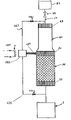
- FIG. 1 is a representation of one preferred system for the operation of this invention wherein the cryocooler is a pulse tube type cryocooler.
- FIG. 2 is a representation of another preferred system for the operation of this invention wherein the cryocooler is a Gifford-McMahon type cryocooler.
- a getter is positioned to intercept some of the working gas of a cryocooler upstream of the regenerator and before it reaches the cold portion or cold end of the cryocooler.
- contaminants which may be in the working gas are adsorbed onto the getter material.
- the cleaned working gas portion is returned to the pressure wave pathway at a warm portion, either upstream or downstream of the regenerator.
- contaminants are continuously removed from the working gas, thus improving the efficiency of the cryocooler operation and extending the time period between required maintenance.
- pressure wave generator 1 which may be a compressor driven by a linear or rotary motor, generates a pulsing gas to drive a cryocooler such as the pulse tube cryocooler illustrated in FIG. 1 .
- the pulsing working gas pulses within the pressure wave pathway which comprises the pressure wave generator, a regenerator and a thermal buffer volume.
- the pressure wave pathway also includes a reservoir downstream of the thermal buffer volume.
- the working gas comprises helium.
- gases which may be used as working gas in the practice of this invention include neon, argon, xenon, nitrogen, air, hydrogen and methane. Mixtures of two or more such gases may also be used as the working gas.
- the pulsing working gas applies a pulse to the hot end of the regenerator 20 thereby generating an oscillating working gas and initiating the first part of the pulse tube sequence.
- the pulse serves to compress the working gas producing hot compressed working gas at the hot end of the regenerator 20 .
- the hot working gas is cooled, preferably by indirect heat exchange with heat transfer fluid in hot heat exchanger 21 to cool the compressed working gas of the heat of compression.
- Heat exchanger 21 is the heat sink for the heat pumped from the refrigeration load against the temperature gradient by the regenerator 20 as a result of the pressure-volume work generated by the pressure wave generator.
- Regenerator 20 contains heat transfer media.
- suitable heat transfer media in the practice of this invention include steel balls, wire mesh, high density honeycomb structures, expanded metals, lead balls, copper and its alloys, complexes of rare earth element(s) and transition metals.
- the pulsing or oscillating working gas is cooled in regenerator 20 by direct heat exchange with cold heat transfer media to produce cold pulse tube working gas.
- Thermal buffer volume or tube 40 which in the arrangement illustrated in FIG. 1 is a pulse tube, and regenerator 20 are in flow communication.
- the flow communication includes cold heat exchanger 30 .
- the cold working gas passes to cold heat exchanger 30 and from cold heat exchanger 30 to the cold end of thermal buffer tube 40 .
- Within cold heat exchanger 30 the cold working gas is warmed by indirect heat exchange with a refrigeration load thereby providing refrigeration to the refrigeration load. This heat exchange with the refrigeration load is not illustrated.
- a refrigeration load is for use in a magnetic resonance imaging system.
- Another example of a refrigeration load is for use in high temperature superconductivity.
- the working gas is passed from the regenerator 20 to thermal buffer tube 40 at the cold end. As the working gas passes into thermal buffer volume 40 , it compresses gas in the thermal buffer volume or tube and forces some of the gas through warm heat exchanger 43 and orifice 50 in line 51 into the reservoir 52 . Flow stops when pressures in both the thermal buffer tube and the reservoir are equalized.
- Cooling fluid is passed to warm heat exchanger 43 wherein it is warmed or vaporized by indirect heat exchange with the working gas, thus serving as a heat sink to cool the compressed working gas.
- the resulting warmed or vaporized cooling fluid is withdrawn from heat exchanger 43 .
- the working gas within the thermal buffer tube expands and thus cools, and the flow is reversed from the now relatively higher pressure reservoir 52 into the thermal buffer tube 40 .
- the cold working gas is pushed into the cold heat exchanger 30 and back towards the warm end of the regenerator while providing refrigeration at heat exchanger 30 and cooling the regenerator heat transfer media for the next pulsing sequence.
- Orifice 50 and reservoir 52 are employed to maintain the pressure and flow waves in phase so that the thermal buffer tube generates net refrigeration during the compression and the expansion cycles in the cold end of thermal buffer tube 40 .
- thermal buffer tube 40 rejects the remainder of pressure-volume work generated by the compression as heat into warm heat exchanger 43 .
- the expanded working gas emerging from heat exchanger 30 is passed to regenerator 20 wherein it directly contacts the heat transfer media within the regenerator to produce the aforesaid cold heat transfer media, thereby completing the second part of the pulse tube refrigerant sequence and putting the regenerator into condition for the first part of a subsequent pulse tube refrigeration sequence.
- a portion of the working gas is taken from the pressure wave pathway downstream of pressure wave generator 1 and upstream of regenerator 20 , and passed in line 126 to getter 122 .
- the working gas passed to the getter may contain contaminants such as oxygen, nitrogen, moisture, carbon dioxide and/or carbon containing species which may have outgassed or desorbed from cryocooler components, leaked in from the air, or were impurities in the working gas charged to the cryocooler.
- the getter material may comprise one or more of metal hydride materials, zirconium-aluminum alloys, zirconium-iron alloys, zeolites, perovskites, inorganic salts such as sodium carbonate and sodium hydroxide, calcium aluminosilicate, activated carbon, silica gel, other metal alloys such as zirconium-cobalt and metals such as vanadium.
- metal hydride materials zirconium-aluminum alloys, zirconium-iron alloys, zeolites, perovskites, inorganic salts such as sodium carbonate and sodium hydroxide, calcium aluminosilicate, activated carbon, silica gel, other metal alloys such as zirconium-cobalt and metals such as vanadium.
- FIG. 1 illustrates two alternatives for returning cleaned working gas from the getter to the pressure wave pathway.
- the cleaned working gas is passed to the pressure wave pathway in line 127 between the warm heat exchanger and the reservoir thus enabling work recovery.
- the cleaned working gas is returned to the pressure wave pathway upstream of the regenerator during a return pulse such as back through line 126 .
- Valves 128 and 129 are employed on lines 127 and 126 respectively enabling the getter to be replaced while the cryocooler is in operation.
- the getter matrix is maintained at a temperature within the range of from 150 to 350K to improve the adsorption of contaminants onto the getter material.
- One preferred method for cooling the getter matrix is by heat exchange with heat transfer fluid, e.g. cooling water, air, etc., employing heat exchanger 125 .
- this refrigeration transfer is from cold heat exchanger 30 to getter 122 by means of heat pipe 124 .
- the getter is placed such that the associated volume complements the performance of the cryocooler.
- the getter provides the resistive part of the total impedance in the loop.
- a side branch at the warm end of the cryocooler contains the getter and provides a volume that optimizes the acoustic compliance in the cryocooler.
- the performance of the cryocooler may be determined by acoustic resonance in the cryocooler. Acoustic resonance is highly dependent upon the volume of the gas present in the cryocooler. Thus manipulating the volume enables the fine tuning for resonance in the cryocooler. Additionally, manipulating the volume also changes the phase and magnitude of the acoustic wave in the cryocooler. Thus an optimum phase and magnitude may be reached by using an optimum volume.
- FIG. 2 illustrates the operation of the invention with reference to a Gifford-McMahon cryocooler.
- the pressure wave pathway includes pressure wave generator or compressor 60 , regenerator 61 and thermal buffer volume or displacer 62 .
- Compressor 60 generates a pulse in a working gas.
- the pressure pulse is directed into regenerator 61 by rotary valve 63 .
- the pressure pulse results in expansion/contraction of the working gas inside regenerator 61 .
- the cold end of the regenerator provides refrigeration by direct contact or indirectly by means of cold heat exchanger 64 .
- the pressure wave may follow two paths, the main path and a small side branch.
- the pressure wave in the main path continues through to the regenerator, the pressure wave in the side branch is forced through a matrix of getter material in getter 65 .
- the getter removes contaminants from the working gas in a manner similar to that described above with reference to FIG. 1 .
- the side branch is designed with dimensions such that it does not interfere with the pressure wave in the main path.
- the working gas that enters the side branch is purified of contaminants due to the getter. As the pressure wave reverses its direction, the purified gas mixes with the gas in the main path. As a result, a net purification of the working gas is achieved.
Abstract
Description
-
- (A) passing a pressure wave through a pressure wave pathway comprising a pressure wave generator, a regenerator and a thermal buffer volume;
- (B) passing gas from the pressure wave pathway upstream of the regenerator to a getter; and
- (C) passing gas from the getter to the pressure wave pathway.
Claims (7)
Priority Applications (1)
| Application Number | Priority Date | Filing Date | Title |
|---|---|---|---|
| US10/978,520 US7219501B2 (en) | 2004-11-02 | 2004-11-02 | Cryocooler operation with getter matrix |
Applications Claiming Priority (1)
| Application Number | Priority Date | Filing Date | Title |
|---|---|---|---|
| US10/978,520 US7219501B2 (en) | 2004-11-02 | 2004-11-02 | Cryocooler operation with getter matrix |
Publications (2)
| Publication Number | Publication Date |
|---|---|
| US20060090478A1 US20060090478A1 (en) | 2006-05-04 |
| US7219501B2 true US7219501B2 (en) | 2007-05-22 |
Family
ID=36260235
Family Applications (1)
| Application Number | Title | Priority Date | Filing Date |
|---|---|---|---|
| US10/978,520 Active 2025-09-10 US7219501B2 (en) | 2004-11-02 | 2004-11-02 | Cryocooler operation with getter matrix |
Country Status (1)
| Country | Link |
|---|---|
| US (1) | US7219501B2 (en) |
Cited By (3)
| Publication number | Priority date | Publication date | Assignee | Title |
|---|---|---|---|---|
| US20080115520A1 (en) * | 2006-11-17 | 2008-05-22 | Bruker Biospin Gmbh | Rinsable cold head for a cryo refrigerator using the pulse tube principle |
| US20090302844A1 (en) * | 2008-06-09 | 2009-12-10 | Sumitomo Heavy Industries, Ltd. | Regenerative expansion apparatus, pulse tube cryogenic cooler, magnetic resonance imaging apparatus, nuclear magnetic resonance apparatus, superconducting quantum interference device flux meter, and magnetic shielding method of the regenerative expansion apparatus |
| CN113154715A (en) * | 2021-04-13 | 2021-07-23 | 中国科学院上海技术物理研究所 | Coaxial active phase modulation power recovery pulse tube refrigerator |
Families Citing this family (1)
| Publication number | Priority date | Publication date | Assignee | Title |
|---|---|---|---|---|
| DE102006025737B4 (en) * | 2006-05-31 | 2016-09-22 | Ald Vacuum Technologies Gmbh | Device for gas quenching of heat-treated components and method for carrying out gas quenching |
Citations (11)
| Publication number | Priority date | Publication date | Assignee | Title |
|---|---|---|---|---|
| US3205679A (en) * | 1961-06-27 | 1965-09-14 | Air Prod & Chem | Low temperature refrigeration system having filter and absorber means |
| US3360955A (en) * | 1965-08-23 | 1968-01-02 | Carroll E. Witter | Helium fluid refrigerator |
| US3793846A (en) * | 1972-11-28 | 1974-02-26 | Hughes Aircraft Co | Decontamination method and apparatus for cryogenic refrigerators |
| USRE33878E (en) * | 1987-01-20 | 1992-04-14 | Helix Technology Corporation | Cryogenic recondenser with remote cold box |
| US5317878A (en) * | 1990-02-28 | 1994-06-07 | British Technology Group Ltd. | Cryogenic cooling apparatus |
| US5470612A (en) | 1991-11-29 | 1995-11-28 | The United States Of America As Represented By The Secretary Of The Air Force | Aerogel mesh getter |
| US6216467B1 (en) | 1998-11-06 | 2001-04-17 | Helix Technology Corporation | Cryogenic refrigerator with a gaseous contaminant removal system |
| US6374617B1 (en) | 2001-01-19 | 2002-04-23 | Praxair Technology, Inc. | Cryogenic pulse tube system |
| US6393844B1 (en) | 2000-08-22 | 2002-05-28 | Raytheon Company | Pulse tube expander having a porous plug phase shifter |
| US6640553B1 (en) | 2002-11-20 | 2003-11-04 | Praxair Technology, Inc. | Pulse tube refrigeration system with tapered work transfer tube |
| US7024867B2 (en) * | 2004-05-18 | 2006-04-11 | Praxair Technology, Inc. | Method for operating a cryocooler using on line contaminant monitoring |
-
2004
- 2004-11-02 US US10/978,520 patent/US7219501B2/en active Active
Patent Citations (11)
| Publication number | Priority date | Publication date | Assignee | Title |
|---|---|---|---|---|
| US3205679A (en) * | 1961-06-27 | 1965-09-14 | Air Prod & Chem | Low temperature refrigeration system having filter and absorber means |
| US3360955A (en) * | 1965-08-23 | 1968-01-02 | Carroll E. Witter | Helium fluid refrigerator |
| US3793846A (en) * | 1972-11-28 | 1974-02-26 | Hughes Aircraft Co | Decontamination method and apparatus for cryogenic refrigerators |
| USRE33878E (en) * | 1987-01-20 | 1992-04-14 | Helix Technology Corporation | Cryogenic recondenser with remote cold box |
| US5317878A (en) * | 1990-02-28 | 1994-06-07 | British Technology Group Ltd. | Cryogenic cooling apparatus |
| US5470612A (en) | 1991-11-29 | 1995-11-28 | The United States Of America As Represented By The Secretary Of The Air Force | Aerogel mesh getter |
| US6216467B1 (en) | 1998-11-06 | 2001-04-17 | Helix Technology Corporation | Cryogenic refrigerator with a gaseous contaminant removal system |
| US6393844B1 (en) | 2000-08-22 | 2002-05-28 | Raytheon Company | Pulse tube expander having a porous plug phase shifter |
| US6374617B1 (en) | 2001-01-19 | 2002-04-23 | Praxair Technology, Inc. | Cryogenic pulse tube system |
| US6640553B1 (en) | 2002-11-20 | 2003-11-04 | Praxair Technology, Inc. | Pulse tube refrigeration system with tapered work transfer tube |
| US7024867B2 (en) * | 2004-05-18 | 2006-04-11 | Praxair Technology, Inc. | Method for operating a cryocooler using on line contaminant monitoring |
Cited By (4)
| Publication number | Priority date | Publication date | Assignee | Title |
|---|---|---|---|---|
| US20080115520A1 (en) * | 2006-11-17 | 2008-05-22 | Bruker Biospin Gmbh | Rinsable cold head for a cryo refrigerator using the pulse tube principle |
| US20090302844A1 (en) * | 2008-06-09 | 2009-12-10 | Sumitomo Heavy Industries, Ltd. | Regenerative expansion apparatus, pulse tube cryogenic cooler, magnetic resonance imaging apparatus, nuclear magnetic resonance apparatus, superconducting quantum interference device flux meter, and magnetic shielding method of the regenerative expansion apparatus |
| US8072219B2 (en) * | 2008-06-09 | 2011-12-06 | Sumitomo Heavy Industries, Ltd. | Regenerative expansion apparatus, pulse tube cryogenic cooler, magnetic resonance imaging apparatus, nuclear magnetic resonance apparatus, superconducting quantum interference device flux meter, and magnetic shielding method of the regenerative expansion apparatus |
| CN113154715A (en) * | 2021-04-13 | 2021-07-23 | 中国科学院上海技术物理研究所 | Coaxial active phase modulation power recovery pulse tube refrigerator |
Also Published As
| Publication number | Publication date |
|---|---|
| US20060090478A1 (en) | 2006-05-04 |
Similar Documents
| Publication | Publication Date | Title |
|---|---|---|
| US5317878A (en) | Cryogenic cooling apparatus | |
| US6378312B1 (en) | Pulse-tube cryorefrigeration apparatus using an integrated buffer volume | |
| CA2561527C (en) | Cryocooler operation using temperature trending monitoring | |
| EP3477225B1 (en) | Cryogenic system | |
| US6644038B1 (en) | Multistage pulse tube refrigeration system for high temperature super conductivity | |
| US7234307B2 (en) | Cryocooler with grooved flow straightener | |
| CA2559201C (en) | Low frequency pulse tube with oil-free drive | |
| US5157938A (en) | Three-stage sorption type cryogenic refrigeration systems and methods employing heat regeneration | |
| US7219501B2 (en) | Cryocooler operation with getter matrix | |
| CN114151989B (en) | Superconducting magnet | |
| US20060225434A1 (en) | Cryocooler assembly with screened regenerator | |
| Ter Brake et al. | 14.5 K hydrogen sorption cooler: Design and breadboard tests | |
| US6484516B1 (en) | Method and system for cryogenic refrigeration | |
| JP2008215783A (en) | Cryogenic refrigerating machine and cryogenic refrigerating method | |
| Burger et al. | DEVELOPMENT OF A 15 K HYDROGEN‐BASED SORPTION COOLER | |
| de Waele | Millikelvin Cooling by Expansion of ³He in 4He | |
| JPH06147686A (en) | Low temperature generator using metal hydride | |
| Bard et al. | Development and Testing of an 80 K Oxide Sorption Cryocooler | |
| JPH0636452Y2 (en) | Cryogenic refrigerator | |
| JP2004347175A (en) | Impulse wave tube refrigerator | |
| JPH04313649A (en) | Refrigerating plant | |
| JPH0735427A (en) | Pulse tube refrigerating machine | |
| JPS63210572A (en) | Cryogenic freezer | |
| JPH09106906A (en) | Conductive cooling superconducting magnet | |
| JP2003004322A (en) | Pulse pipe refrigerating machine without buffer tank |
Legal Events
| Date | Code | Title | Description |
|---|---|---|---|
| AS | Assignment |
Owner name: PRAXAIR TECHNOLOGY INC., CONNECTICUT Free format text: ASSIGNMENT OF ASSIGNORS INTEREST;ASSIGNORS:ZIA, JALAL HUNAIN;ACHARYA, ARUN;ARMAN, BAYRAM;REEL/FRAME:015388/0841;SIGNING DATES FROM 20041021 TO 20041027 |
|
| STCF | Information on status: patent grant |
Free format text: PATENTED CASE |
|
| FPAY | Fee payment |
Year of fee payment: 4 |
|
| FPAY | Fee payment |
Year of fee payment: 8 |
|
| MAFP | Maintenance fee payment |
Free format text: PAYMENT OF MAINTENANCE FEE, 12TH YEAR, LARGE ENTITY (ORIGINAL EVENT CODE: M1553); ENTITY STATUS OF PATENT OWNER: LARGE ENTITY Year of fee payment: 12 |