US7224845B1 - Bijection mapping for compression/denoising of multi-frame images - Google Patents
Bijection mapping for compression/denoising of multi-frame images Download PDFInfo
- Publication number
- US7224845B1 US7224845B1 US10/376,491 US37649103A US7224845B1 US 7224845 B1 US7224845 B1 US 7224845B1 US 37649103 A US37649103 A US 37649103A US 7224845 B1 US7224845 B1 US 7224845B1
- Authority
- US
- United States
- Prior art keywords
- image
- multispectral
- mapping
- compression
- correlation
- Prior art date
- Legal status (The legal status is an assumption and is not a legal conclusion. Google has not performed a legal analysis and makes no representation as to the accuracy of the status listed.)
- Expired - Fee Related, expires
Links
Images


Classifications
-
- H—ELECTRICITY
- H04—ELECTRIC COMMUNICATION TECHNIQUE
- H04N—PICTORIAL COMMUNICATION, e.g. TELEVISION
- H04N19/00—Methods or arrangements for coding, decoding, compressing or decompressing digital video signals
- H04N19/60—Methods or arrangements for coding, decoding, compressing or decompressing digital video signals using transform coding
- H04N19/63—Methods or arrangements for coding, decoding, compressing or decompressing digital video signals using transform coding using sub-band based transform, e.g. wavelets
- H04N19/64—Methods or arrangements for coding, decoding, compressing or decompressing digital video signals using transform coding using sub-band based transform, e.g. wavelets characterised by ordering of coefficients or of bits for transmission
- H04N19/647—Methods or arrangements for coding, decoding, compressing or decompressing digital video signals using transform coding using sub-band based transform, e.g. wavelets characterised by ordering of coefficients or of bits for transmission using significance based coding, e.g. Embedded Zerotrees of Wavelets [EZW] or Set Partitioning in Hierarchical Trees [SPIHT]
-
- G—PHYSICS
- G06—COMPUTING; CALCULATING OR COUNTING
- G06V—IMAGE OR VIDEO RECOGNITION OR UNDERSTANDING
- G06V20/00—Scenes; Scene-specific elements
- G06V20/10—Terrestrial scenes
- G06V20/13—Satellite images
-
- H—ELECTRICITY
- H04—ELECTRIC COMMUNICATION TECHNIQUE
- H04N—PICTORIAL COMMUNICATION, e.g. TELEVISION
- H04N19/00—Methods or arrangements for coding, decoding, compressing or decompressing digital video signals
- H04N19/10—Methods or arrangements for coding, decoding, compressing or decompressing digital video signals using adaptive coding
- H04N19/102—Methods or arrangements for coding, decoding, compressing or decompressing digital video signals using adaptive coding characterised by the element, parameter or selection affected or controlled by the adaptive coding
-
- H—ELECTRICITY
- H04—ELECTRIC COMMUNICATION TECHNIQUE
- H04N—PICTORIAL COMMUNICATION, e.g. TELEVISION
- H04N19/00—Methods or arrangements for coding, decoding, compressing or decompressing digital video signals
- H04N19/10—Methods or arrangements for coding, decoding, compressing or decompressing digital video signals using adaptive coding
- H04N19/134—Methods or arrangements for coding, decoding, compressing or decompressing digital video signals using adaptive coding characterised by the element, parameter or criterion affecting or controlling the adaptive coding
- H04N19/136—Incoming video signal characteristics or properties
- H04N19/14—Coding unit complexity, e.g. amount of activity or edge presence estimation
-
- H—ELECTRICITY
- H04—ELECTRIC COMMUNICATION TECHNIQUE
- H04N—PICTORIAL COMMUNICATION, e.g. TELEVISION
- H04N19/00—Methods or arrangements for coding, decoding, compressing or decompressing digital video signals
- H04N19/10—Methods or arrangements for coding, decoding, compressing or decompressing digital video signals using adaptive coding
- H04N19/189—Methods or arrangements for coding, decoding, compressing or decompressing digital video signals using adaptive coding characterised by the adaptation method, adaptation tool or adaptation type used for the adaptive coding
-
- H—ELECTRICITY
- H04—ELECTRIC COMMUNICATION TECHNIQUE
- H04N—PICTORIAL COMMUNICATION, e.g. TELEVISION
- H04N19/00—Methods or arrangements for coding, decoding, compressing or decompressing digital video signals
- H04N19/90—Methods or arrangements for coding, decoding, compressing or decompressing digital video signals using coding techniques not provided for in groups H04N19/10-H04N19/85, e.g. fractals
Definitions
- the present invention relates to algorithms and more particularly to algorithms useful in image compression.
- the number of systems generating multiple images of the same scene at different frequency bands and their applications have rapidly increased in the last several years.
- Remote sensing systems, thematic mapper sensors, and multispectral Forward Looking Infrared (FLIR) systems are only a few examples of such systems.
- the data product of a multispectral sensor is a stack of images for each scene referred to as a multispectral image or data cube.
- Each band or component of a multispectral image can be considered as a monochrome (scalar) image.
- Multispectral imagery provides signal diversity that can lead to more precise and accurate results than otherwise possible with traditional single spectral imagery.
- a major limitation of multispectral imaging systems in practice is the required manipulation and delivery of the associated massive data files. In order to store and transmit such files, very efficient compression tools are needed. Because of this need, this disclosure shall focus on a new method for lossy compression. True lossless compression is limited in performance; here, we allow the compression to be lossy but implicitly maintain control over the fidelity of the compressed imagery so
- the compression rate for each eigen-image is determined through a bit allocation strategy.
- Other 2-stage compression methods first decorrelate the data by applying a 2D frequency transform along the spatial dimensions and a 1-dimensional KLT is subsequently applied across the spectral dimension as is disclosed in D. Tretter, C. A. Bouman, “Optical transforms for multispectral and multilayer image coding,” IEEE TIP: 4:296–308, March, 1995, J. N. Bradley & C. M. Brislawn; “Spectrum analysis of multispectral imagery in conjunction with wavelet/kit data compression,” Proc. ASIMOLAR Conf. 1:26–30, November, 1993; and J. Vaisey, M. Barlaud & M.
- M 1 ⁇ M 2 multispectral image f(m)) [f 1 (m), f 2 (m), . . . , f L (m)] T with L bands.
- the multispectral image is thus composed of M 1 ⁇ M 2 f-vectors of length L.
- the image is then processed by the two-stage compression method described above, where a 1-Dimension KLT is applied along the spectral dimension.
- the resultant KLT coefficients form a set of images, ⁇ g 1 (m), g 2 (m), . . .
- FIG. 1 depicts the KLT of a 2-band image into a pair of decorrelated eigen-images. A three-level wavelet decomposition of each eigen-image is also shown. These images clearly show that although the eigen-images are decorrelated across bands at a particular pixel location, cross-band correlation among groups of pixels remains. The residual cross-band correlation results in a strong spatial similarity not exploited by the wavelet transforms applied to each eigen-image. In fact, FIG. 1 shows that spatial similarity remains after the wavelet transforms are applied.
- a 3D (3D) zero-tree coder for instance, can be designed to jointly exploit the intra-band and cross-band correlations inherent in a data cube as is disclosed in A. Bilgin, G. Zweig & M. W. Marcellin, “Three-dimensional Image Compression using Integer Wavelets,” Appl. Optics, 39#11:1799–1814, April, 2000. This, however, can become very complex since the number bands to be jointly encoded can be quite large.
- the bands are typically separable in three-dimensions and the zero-tree coder spawns children at a cubic rate having implications for the production of zero-trees.
- three-dimensional data may be processed via some three-dimensional extension of a well-known transform such as the DCT G. Abousleman, M. W. Marcellin & B. Hunt, “Compression of Hyperspectral Imagery using 3-D DCT and Hybrid DPCM/DCT,” IEEE TGRS 33#1:26–34, January, 1995.
- a well-known transform such as the DCT G. Abousleman, M. W. Marcellin & B. Hunt, “Compression of Hyperspectral Imagery using 3-D DCT and Hybrid DPCM/DCT,” IEEE TGRS 33#1:26–34, January, 1995.
- DCT G. Abousleman, M. W. Marcellin & B. Hunt “Compression of Hyperspectral Imagery using 3-D DCT and Hybrid DPCM/DCT,” IEEE TG
- the present invention is an approach to multispectral image compression where the intra- and cross-band correlations are jointly exploited in a surprisingly simple yet very effective manner.
- the method is based on the fact that it is more efficient to jointly encode all the components of a vector source than to encode each component separately as is disclosed in A. Segall, “Bit allocation and encoding for vector sources,” IEEE Trans. Inf. Thy. IT-22:162–169, March 1976.
- the key component of the algorithm is a simple transformation, a bijection mapping of the original multispectral image into a virtual two-dimensional (2D) scalar image.
- 2D virtual two-dimensional
- the SPIHT codec need not be modified for 3D operation.
- the choice of the bijection mapping will determine the way in which spatial and spectral information are combined: there is no intrinsic limit in number of bands processed at a time nor in the way spectral and spatial pixels are combined.
- Combining the bijection mapping with the SPIHT codec gives a no frills, low complexity method for processing multispectral data. This may be improved by selecting the optimal bijection mapping which is equivalent to the problem of finding a permutation map which reduces activity across pixels to effect pixel prediction.
- FIG. 1 is a schematic drawing showing a two-stage approach for compression of a multispectral, two-color FLIR image, wherein spectral transform is followed by 2-D DWT and the multispectral image is a two-color focal plane array LWIR/MWIR;
- FIG. 3 is a schematic drawing showing two bijection mappings of a 1 ⁇ 2 ⁇ 4 (4-band) stack into (a) a 1 ⁇ 8 array, and (b) a 2 ⁇ 4 array;
- FIGS. 4( a ) and 4 ( b ) are flow charts, wherein FIG. 4( a ) shows a compression algorithm: bijection mapping follow by SPIHT encoder, and FIG. 4( b ) shows a decompression algorithm: SPIT decoder followed by inverse bijection mapping;
- FIGS. 5( a ) and ( b ) are schematic drawings showing two different bijection mappings of the bispectral FLIR image
- FIGS. 6( a )– 6 ( d ) are graphs of lines of images ouputted by bijection mapping in FIG. 5 , wherein FIG. 6( a ) depicts the marked line in FIG. 5( a ) and FIG. 6( c ) depicts the marked line in FIG. 5( b ), and FIGS. 6( b ) and 6 ( d ) depict the same lines after images are compressed;
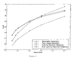
- FIG. 7 is a graph of average PSNR of the four reconstructed bands achieved by the various compression algorithm.
- FIGS. 8( a )– 8 ( d ) show the second band of the reconstructed images at 0.08 bit/pixel/band wherein FIG. 8( a ) is the original band, FIG. 8( b ) shows a separable approach, FIG. 8( c ) is from a traditional two-stage algorithm, and FIG. 8( d ) is from bijection mapping onto zeros trees;
- FIG. 9 is a graph showing performance of the different compression algorithms acting on unobserved data
- FIGS. 10( a )– 10 ( d ) show the first band of the non-training image at 0.1 bit/pixel/band, wherein FIG. 10( a ) is the original, FIG. 10( b ) shows a separable approach, FIG. 10( c ) is from a traditional two-stage approach, and FIG. 10( d ) is from bijection mapping onto zero trees;
- FIGS. 11( a )– 11 ( d ) show band VH of the polarimetric SAR data at 0.4 bit/pixel/band, wherein FIG. 11( a ) is the original image, FIG. 11( b ) is from a separable approach, FIG. 11( c ) is from a two-stage approach, and FIG. 11( d ) is from bijection mapping onto zero-trees; and
- FIG. 12 is a graph showing coding performance achieved by the various algorithms on Polarimetric SAR data.
- a bijection mapping is a one-to-one onto function that maps set A to set B.
- the set A is called the domain of ⁇ (x) and the set of all elements ⁇ (x) ⁇ B is called the range of ⁇ (x).
- ⁇ ⁇ 1 (x) is called the inverse of the function ⁇ (x).
- R M 1 ⁇ M 2 be the set of M 1 ⁇ M 2 arrays defined over the set of real numbers R.
- R M 1 ⁇ M 2 ⁇ L be the set of M 1 ⁇ M 2 arrays where each element in the array is a L-component vector defined over the set of real numbers. For instance, if f ⁇ R M 1 ⁇ M 2 ⁇ L , then f has the following structure
- f L (m 1 ,m 2 )] T is an L-component vector and where each element of f(m 1 ,m 2 ) is defined over the set of real numbers, i.e. f k (m 1 ,m 2 ) ⁇ R.
- a M 1 ⁇ M 2 multispectral image with L bands is an example of an element in R M 1 ⁇ M 2 ⁇ L
- each M 1 ⁇ M 2 monochrome (scalar) image belongs to the set R M 1 ⁇ M 2 .
- the bijection mappings utilized in this paper are defined as a one-to-one permutation of the elements in R M 1 ⁇ M 2 ⁇ L onto the set R L 1 M 1 ⁇ L 2 M 2 .
- the bijection mapping of a multispectral image is thus defined as a mapping of the 3D data stack into a 2D virtual image. This mapping includes normalization such that neighboring pixels in the virtual image have similar dynamic range. The mapping is invertible since the original data cube can be perfectly reconstructed from the virtual two-dimensional array.
- R M 1 ⁇ M 2 ⁇ L represents the set of M 1 ⁇ M 2 multispectral images with L bands
- B(R M 1 ⁇ M 2 ⁇ L ) represents the associated set of two-dimensional arrays.
- a simpler approach to handle large image files is to break the multispectral image stack into smaller non-overlapping sub-images of depth L. That is, the spatial domain is partitioned while the spectral dimension is not, as L is typically in the order of 15 or less for multispectral images.
- the bijection mapping of a multispectral image thus reduces to the bijection mapping of N 1 ⁇ N 2 ⁇ L image cells as depicted in FIG. 3 . Assuming that the images are homogeneous, all cells are treated equally and the same bijection mapping is applied to all image cells. This concept could be generalized where various types of bijection mappings are applied to different image cells depending on their statistical characteristics. For the sake of simplicity, at this time, we treat all cells uniformly.
- the multispectral image is first divided into cells of size N 1 ⁇ N 2 ⁇ L. Each 3D cell is then subjected, independently of the others, to a bijection mapping. The resultant two-dimensional arrays are placed into a large single array according to the position of the original 3D cells.
- FIG. 3 shows two different bijection mappings of a four-band cube, where the size of each cell is 1 ⁇ 2 ⁇ 4. In FIG. 3( a ), each cell is mapped to a 1 ⁇ 8 array, i.e., B:R 1 ⁇ 2 ⁇ 4 ⁇ R 1 ⁇ 8 .
- FIG. 3( b ) shows a different bijection mapping where each cell is mapped to a 2 ⁇ 4 array.
- E c E u E T ( 4 ) and E ll is the energy compacted in the approximation of the wavelet decomposition. In compression, higher E c generally translates into smaller distortion in the reconstructed data.
- N 1 ⁇ N 2 The approach to the design of the image partition size N 1 ⁇ N 2 is through heuristics, although other more elaborated approaches can be used.
- the type of the 2D transform used in the encoding stage determines the shape of the partition cell.
- SPIHT uses a two-dimensional discrete wavelet transform that exploits the correlation by filtering the image first along the rows and then along the columns. This fact provides a reliable guideline defining N 1 and N 2 as well as the shape of the two-dimensional array, i.e. L 1 and L 2 , inherent in the bijection mapping.
- ⁇ k and ⁇ k are given respectively by:
- cov(x,y), var(x) and x denote the covariance, variance and mean respectively
- P in (5) is an LN 2 ⁇ LN 2 matrix that contains exactly one 1 in each row and column.
- P is referred here to as a permutation matrix since it defines the re-ordering of the pixels into the array G.
- I N is an N ⁇ N identity matrix
- 0 N is an N ⁇ N all zero matrix
- J N is an N ⁇ N right-to-left diagonal matrix
- FIG. 5 shows two different bijection mappings of a bispectral FLIR image. Although the images outputted by the two different bijection mappings look similar, they have markedly different characteristics. To observe their differences better, FIG. 6( a ) and FIG. 6( c ) depict horizontal scans marked as white lines in FIG. 5 . Note that the line shown in FIG. 6( c ) is smoother than the one plotted in FIG. 6( a ). FIG. 6( b ) and FIG. 6( d ) show the same lines after the virtual images outputted by the bijection mappings have been compressed/decompressed. The reconstructed line of FIG. 6( d ) is less distorted than the one depicted in FIG. 6( b ).
- the optimal bijection mapping B is the one that generates the smoothest virtual image which is the most suitable image for compression.
- image smoothness we use the correlation between consecutive samples in the virtual image. Finding the optimal bijection mapping reduces to finding the best re-ordering of the samples in the virtual image that maximizes the spatial correlation.
- g P ⁇ tilde over (f) ⁇ be a re-ordered vector of ⁇ tilde over (f) ⁇ produced by the permutation matrix P.
- r i,j be the correlation between the i th and j th components of g p . Since ⁇ tilde over (f) ⁇ is formed by concatenating N 2 consecutive normalized vector-valued pixels, r i,j represents the spectral correlation, or the spatial correlation, or the cross-correlation between pixels.
- the objecting function to be maximized is then given by
- the key in the sub-optimal bijection mapping is to keep, as close as possible, those pixels that have a high correlation. Moreover, it takes into account both the spectral and spatial correlations in defining the re-ordering of the samples. For both optimal and sub-optimal solutions, N 2 has to be set to a small number (between 2 and 6). The reason for doing so lies in the fact that the spatial correlation decays rapidly as the distance between pixels increases.
- the proposed compression algorithm was applied to 4-band airborne multispectral data collected using the AISA Airborne Imaging Spectrometer. Each band is a monochrome 8 bit image of size 384 ⁇ 700. A 256 ⁇ 256 pixel area in the upper left part of each band is used as training data to compute the correlation matrix needed for the optimization algorithm.
- the optimal bijection mapping, B 0 is determined following the algorithm described in Section 3. The data is partitioned into 1 ⁇ 2 ⁇ 4 m cells. The bijection mapping B 0 :R 1 ⁇ 2 ⁇ 4 ⁇ R 1 ⁇ 8 is then applied to each cell to form the virtual image that is compressed by the SPIHT coder at a compression rate from 0.05 bit/pixel/band to 1 bit/pixel/band. The sub-optimal bijection mapping is also determined and used here for comparison.
- the first algorithm compresses each spectral band separately using the SPIHT coder, and thus only takes advantage of the spatial redundancy in the image set.
- This compression algorithm referred here to as the separable approach, as a benchmark to see the advantage of exploiting all the redundancy existing in a multispectral data.
- the second algorithm uses the two-stage approach described in the introduction. That is, the KLT is computed along the spectral dimension to obtain the 4 eigen-planes.
- the SPIHT coder is then used to compress each eigen-plane at a compression rate that is proportional to the logarithm of the energy of the eigen-plane.
- PSNR Peak Signal-to-Noise Ration
- FIG. 7 shows the average PSNR obtained using the proposed algorithm (optimal and sub-optimal bijection mappings) and the algorithms described above for a compression rate between 0.05 bit/pixel/band to 1 bit/pixel/band.
- FIG. 8 shows the second reconstructed band yielded by the different compression algorithms at a compression rate of 1:100 or equivalently 0.08 bit/pixel/band.
- FIG. 8( a ) shows the original second band
- FIG. 8( b ) shows the performance achieved if each band is separately compressed; i.e. not spectral correlation is exploited.
- FIG. 8( c ) shows the reconstructed image yielded by the two-stage algorithm and
- FIG. 8( d ) depicts the corresponding band when the proposed compression method is taken.
- the sub-optimal bijection mapping yields similar visual performance to that of the optimal bijection mapping; therefore, its reconstructed image is not shown. Note that in the reconstructed image obtained using the proposed algorithm, the details are preserved and the edges are well defined. By comparison, there is noticeable blurring for the other reconstructions. Note also the poor performance that is achieved when the spectral correlation is not exploited. As can be seen by comparing the images and the PSNR curve of FIG. 7 the proposed compression method is simple yet very efficient particularly at very high compression rates.
- FIG. 9 shows the performance of the different algorithms acting on an unobserved data set. Observe that the two-stage approach is more data dependent than the proposed algorithm since the proposed approach outperforms the two-stage approach over a much wider range of compression rate.
- FIG. 10( a ) shows the first band of the original unobserved data
- FIGS. 10 ( b ), ( c ) and ( d ) show the corresponding reconstructed images using the separable approach, the two-stage approach and the proposed algorithm respectively.
- FIG. 11 ( a ) shows the Vertical-Horizontal (VH) polarization of the test data.
- FIG. 11( b ) shows the performance of the separable approach.
- FIGS. 11( c ) and ( d ) show the performance of the two-stage approach and the proposed approach, respectively.
- the reconstructed images shown in FIG. 11 are compressed 20:1. Note that at this compression the separable and two-stage algorithms exhibit ringing artifacts which are very disturbing.
- the PSNRs obtained using the different compression algorithms are displayed in FIG. 12 .
- the bijection mapping onto zero-tree outperforms the other two methods by approximately 0.5 dB.
- the proposed method uses a bijection mapping to project the 3D data cube into a two-dimensional array.
- a scalar image compression coder then compresses the obtained two-dimensional image.
- An optimization algorithm is developed to find the optimal parameters of the bijection mapping that leads to the most suitable virtual image for compression.
- the performance of the proposed compression algorithm was compared with those found using the separable approach and the traditional two-stage approach. In general, at very high compression rates, the bijection compression approach yields superior results, both perceptually and in the PSNR distortion measure.
- the spatial correlation matrices for each spectral signal is given by
- a simple spatial correlation model is assumed for mathematical tractability.
- the correlation structure of the autocorrelation matrix may not be particularly accurate for multispectral imagery; however, the assumption of the more or less the same autocorrelation is a valid assumption as the multispectral images will be, more or less, similar. Since both f 1 and f 2 view the same scene, cross-spectral correlation between them exists.
- the maximum energy preserved is determined by the two highest eigenvalues, namely:
- Equation (6) The normalization factors given in Equation (6) are derived here.
- f k be k-th spectral component of a multispectral image.
- the pixel's spatial position index has been dropped.
- ⁇ tilde over (f) ⁇ k the resultant normalized component, denoted by ⁇ tilde over (f) ⁇ k , has the same dynamic range than the other normalized components.
- f be the average of the different spectral components, that is
- ⁇ k and ⁇ k are chosen to minimize the following cost function min ⁇ k , ⁇ k E( ⁇ tilde over (f) ⁇ k ⁇ f ) 2 (19) It can be easily shown that the values of ⁇ k and ⁇ k that minimize the MSE between the k th normalized component and the spectral average image are given by:
- cov(x,y), var(x) and x denote the covariance, variance and mean respectively.
Landscapes
- Engineering & Computer Science (AREA)
- Multimedia (AREA)
- Signal Processing (AREA)
- Physics & Mathematics (AREA)
- General Physics & Mathematics (AREA)
- Astronomy & Astrophysics (AREA)
- Remote Sensing (AREA)
- Theoretical Computer Science (AREA)
- Compression Or Coding Systems Of Tv Signals (AREA)
Abstract
Description
-
- 1. Image decorrelation is performed in a separable fashion, first along the spectral dimension and subsequently along the spatial dimension or vice versa. The separable approach is intrinsically suboptimal as the spatial and spectral statistics are not exploited jointly;
- 2. The KLT is data dependent and consequently it must be computed for each image set resulting in an unacceptable amount of computation;
- 3. Transformed image planes after the initial decorrelation are coded independently of the others, despite of the spatial similarities across bands. The focus of this paper is to introduce a method which exploits spatial and frequency correlation jointly.
where f(m1,m2)=[f1(m1,m2),f2(m1,m2) . . . fL(m1,m2)]T is an L-component vector and where each element of f(m1,m2) is defined over the set of real numbers, i.e. fk(m1,m2)εR. A M1×M2 multispectral image with L bands is an example of an element in RM
B:R M
m1=1, 2, . . . ,M1; m2=1, 2, . . . , M2; k=1, 2, . . . , L; i=1, 2, . . . , L1M1, j=1, 2, . . . , L2M2
where GεRL
B −1 :R L
In summary, RM
-
- 1. Mapping each cell by B:RN
1 ×N2 ×L→RL1 N1 ×L2 N2 into the L1N1×L2N2 array. - 2. Tiling the obtained arrays into a virtual image I.
- 3. Encoding the virtual image I by a zero-tree coder.
- 4. Attaching the type of bijection mapping used as a header.
FIG. 4 shows the proposed compression algorithm. Note that the compressed image is a binary bit string whose length, denoted by S inFIG. 4 , is determined by the compression ratio. Note also that the last step of the proposed algorithm, not shown inFIG. 4 , adds information needed by the decoder to reconstruct the multispectral data. This overhead, however, is negligible compared to the amount of compressed data. As it will be shown shortly, a permutation matrix that defines the re-ordering of the data pixels can compactly represent the bijection mapping. (Figure to be included)
The multispectral image decoder reverses the encoding process by: - 1. Extracting the type of bijection mapping from the file header.
- 2. Reconstructing the virtual image Î with the zero-tree decoder.
- 3. Partitioning the virtual image Î into L1N1×L2N2 cells and mapping back each cell by B−1:RL
1 N1 ×L2 N2 →RN1 ×N2 ×L, to form the reconstructed 3D cells. - 4. Concatenating the obtained cells to form the multispectral image.
Given the bijection mapping onto the zero-tree codec shown inFIG. 4 , the following questions arise. - 1. How are N1 and N2 chosen so as to maximize the attained energy compaction?
- 2. Given N1 and N2 there are (LN1N2)! possible bijection mapping. How does one select a bijection mapping so as to maximize the energy compaction?
Energy compaction, Ec, is defined as where ET is the total energy of the multi spectral image
- 1. Mapping each cell by B:RN
and Ell is the energy compacted in the approximation of the wavelet decomposition. In compression, higher Ec generally translates into smaller distortion in the reconstructed data. The answer to the first question reduces to how much computational complexity can we tolerate? If N1>Ni, i=1,2, and letting {B(N1,N2)} be the set of all possible bijection mappings of a N1×N2 cell, then {B(N1, N2)}⊂{B(N′1, N′2). Hence, we will always do equal or better as N1 and N2 are incremented. The real issue is, how much gain does one attain as Ni is incremented to Ni+1, Ni+2, because the size of the search space increases as (LN1N2)!. It is conceivable that an optimum may be achieved for small values of N1, N2 in which case picking a larger cell adds computation. As N1 is incremented to N1+1, an additional (LN2) possible bijection mapping are added to the search space. A related and perhaps more important question is: if only one parameter is incremented, either N1 or N2, which one should be chosen. In summary, the performance gain as the size of N1 and N2 are monotonically increased, is somewhat reminiscent to the order of an AR model. In fact, some of the same issues that arise on selecting the order of an AR model also arise here such as overfitting, complexity, etc. The second question is perhaps the most important since it is directly related to energy compaction. Having fixed N1 and N2 which one of the (LN1N2)! bijection mappings will maximize the energy compaction? Answers to these questions will be given in
where f(m1,m2) is the vector-valued pixel at (m1,m2), μ=[μ1, μ2, . . . , μL]T and σ=diag(σ1, σ2, . . . , σL) normalize the data set, where σk and μk are chosen such that the resultant normalized spectral components have the same dynamic range. It is shown in Table 2 that σk and μk are given respectively by:
where cov(x,y), var(x) and
is the image obtained by averaging the different spectrum components. Note that in the above equations the spatial index m=(m1,m2) has been dropped for simplicity.
where IN is an N×N identity matrix, 0N is an N×N all zero matrix and JN is an N×N right-to-left diagonal matrix. Note also that
gives re-ordering of the shaded samples into the two-dimensional array. Each permutation matrix defines a different re-ordering and therefore a different bijection mapping. The permutation matrix P defining the re-ordering of the samples thus characterizes a bijection mapping. A fundamental problem is thus the design of P that leads to the highest compression attainable. For a 1×N2×L cell, there exists (LN2)! different re-orderings of the samples inside a cell.
B 0=maxp E c(B(P)), (8)
defined in (4). Since the total energy of a multispectral image does not depend on the bijection mapping nor on the wavelet transform used, (8) reduces to maximizing the energy compacted in the low-frequency components of the wavelet domain. If the wavelet transform is applied to an image that is smooth, having most of its energy in the lowpass band of the spectrum, the resultant energy compaction is high. On the other hand, if the energy of an image is concentrated in the highpass band of the spectrum, the wavelet transform will have more of the energy distributed on the high-frequency components of the wavelet domain, resulting in poor energy compaction.
{tilde over (f)}=[σf(m 1 ,m 2)T+μT ,σf(m 1 ,m 2+1)T+μT , . . . ,σf(m 1 ,m 2 +N 2)T+μT]T.
Furthermore, let g=P{tilde over (f)} be a re-ordered vector of {tilde over (f)} produced by the permutation matrix P. We want to find the best re-ordering of the components of {tilde over (f)} such that the sum of correlations between consecutive components of the re-ordered vector is maximized. Let ri,j be the correlation between the i th and j th components of gp. Since {tilde over (f)} is formed by concatenating N2 consecutive normalized vector-valued pixels, ri,j represents the spectral correlation, or the spatial correlation, or the cross-correlation between pixels. The objecting function to be maximized is then given by
where rLN
Since P{tilde over (f)}, the objective function (9) can be rewritten as a function of the permutation matrix P as follows:
maxPεΩ(E({tilde over (f)}TPTAP{tilde over (f)})), (11)
where Ω is the set of all permutation matrix of size LN2. Thus, finding the best re-ordering of the components of {tilde over (f)} that produces a smooth virtual image reduces to finding the permutation matrix P that maximizes (11). The optimal permutation matrix P is determined using a heuristic search of the space Ω.
- 1. Select the pixels of the band that has the highest spatial correlation, say max(ra, rb, rc, rd)=ra, hence
| a1 | a2 | □ | aN |
||
- 2. On each side of the pixel set attach the pixels corresponding to the band that has the highest spectral correlation with respect to the band found in the previous step, say max(rA,B, rA,C, rA,D)=rA,B, hence the re-ordering becomes
| b1 | b2 | . . . | bN |
a1 | a2 | . . . | aN |
bN |
. . . | bN |
- 3. On each side of the resultant array insert the pixels corresponding to the band that has not been merged yet and that has the highest spectral correlation with respect to the samples added in
step 2, i.e. max (rB,C,rB,D) defines the next band to be multiplexed. Following with the example and assuming that rB,C>rB,D, the re-ordering becomes
| c1 | . . . | cN | b1 | . . . | bN | a1 | . . . | aN | bN | . . . | bN | cN | . . . | cN |
Repeat the previous step up to all the bands are multiplexed into a single band. Figure [REF:fig:bijection](a) shows, for this example, the sub-optimal bijection mapping for N2=2. This four-step procedure is repeated for each 3D cell and the resultant 2D array is tiled in the way described above for the optimal solution. Note that the key in the sub-optimal bijection mapping is to keep, as close as possible, those pixels that have a high correlation. Moreover, it takes into account both the spectral and spatial correlations in defining the re-ordering of the samples. For both optimal and sub-optimal solutions, N2 has to be set to a small number (between 2 and 6). The reason for doing so lies in the fact that the spatial correlation decays rapidly as the distance between pixels increases.
where xi,j is the pixel at the i th row and j th column in the image and {circumflex over (x)}i,j is its corresponding reconstructed pixel. PSNR is separately computed for each band.
where a simple spatial correlation model is assumed for mathematical tractability. The correlation structure of the autocorrelation matrix may not be particularly accurate for multispectral imagery; however, the assumption of the more or less the same autocorrelation is a valid assumption as the multispectral images will be, more or less, similar. Since both f1 and f2 view the same scene, cross-spectral correlation between them exists. For mathematical tractability, assume that the cross-spectral correlation C=E(f1f2 T) is given by
where ρ0>ρ is assumed. Again, the particular correlations may not be reasonable, but the cross-correlation structure is described exactly for this simple case i=1,2. Now, consider the two encoding strategies: (a) each signal is coded individually and (b) a virtual signal is formed by a bijection mapping followed by scalar encoding. For simplicity, the energy preserved in the reconstructed signals after encoding is used as a performance measure. Recall that a signal's energy is given by the sum of the eigenvalues of its correlation matrix. The eigenvalues of Ri, i=1,2, can be computed as:
Note that if each signal is individually compressed at a rate 1:N, the maximum energy preserved in each signal is given by the highest eigenvalue, namely, λ1=r0+Nr. Now, consider the case where both signals are mapped into one larger virtual signal, g=[f1 T, f2 T]T. The correlation matrix of g is given by
whose eigenvalues are
For a compression rate of 1:N, the maximum energy preserved is determined by the two highest eigenvalues, namely:
From (4) and (7), the compression of the virtual image always provides higher energy preservation suggesting the potential the advantage of bijection mappings.
Note that the average is performed for each spatial position m=(m1,m2). We want to normalize fk with respect to
minσk,μkE({tilde over (f)}k−
It can be easily shown that the values of σk and μk that minimize the MSE between the k th normalized component and the spectral average image are given by:
-
- The above equations can be rewritten as follows
where cov(x,y), var(x) and
Claims (20)
Priority Applications (1)
| Application Number | Priority Date | Filing Date | Title |
|---|---|---|---|
| US10/376,491 US7224845B1 (en) | 2002-02-28 | 2003-02-28 | Bijection mapping for compression/denoising of multi-frame images |
Applications Claiming Priority (2)
| Application Number | Priority Date | Filing Date | Title |
|---|---|---|---|
| US36045702P | 2002-02-28 | 2002-02-28 | |
| US10/376,491 US7224845B1 (en) | 2002-02-28 | 2003-02-28 | Bijection mapping for compression/denoising of multi-frame images |
Publications (1)
| Publication Number | Publication Date |
|---|---|
| US7224845B1 true US7224845B1 (en) | 2007-05-29 |
Family
ID=38056807
Family Applications (1)
| Application Number | Title | Priority Date | Filing Date |
|---|---|---|---|
| US10/376,491 Expired - Fee Related US7224845B1 (en) | 2002-02-28 | 2003-02-28 | Bijection mapping for compression/denoising of multi-frame images |
Country Status (1)
| Country | Link |
|---|---|
| US (1) | US7224845B1 (en) |
Cited By (13)
| Publication number | Priority date | Publication date | Assignee | Title |
|---|---|---|---|---|
| US20080112489A1 (en) * | 2006-11-09 | 2008-05-15 | Calista Technologies | System and method for effectively encoding and decoding electronic information |
| US20100118935A1 (en) * | 2004-04-23 | 2010-05-13 | Sumitomo Electric Industries, Ltd. | Coding method for motion-image data, decoding method, terminal equipment executing these, and two-way interactive system |
| CN103024377A (en) * | 2012-11-27 | 2013-04-03 | 西安电子科技大学 | Synthetic aperture radar (SAR) image compression method based on target area extraction and direction wave |
| US20140307975A1 (en) * | 2013-04-10 | 2014-10-16 | Southwest Research Institute | Systems And Methods for Hybrid Compression Of Spectral Image Data |
| US20140325228A1 (en) * | 2010-11-30 | 2014-10-30 | Marvell Israel (M.I.S.L.) Ltd. | Load balancing hash computation for network switches |
| US8929654B2 (en) | 2011-12-28 | 2015-01-06 | Dolby Laboratories Licensing Corporation | Spectral image processing |
| CN104378653A (en) * | 2014-11-27 | 2015-02-25 | 北京邮电大学 | Video block dividing method and device |
| US9876719B2 (en) | 2015-03-06 | 2018-01-23 | Marvell World Trade Ltd. | Method and apparatus for load balancing in network switches |
| US9906592B1 (en) | 2014-03-13 | 2018-02-27 | Marvell Israel (M.I.S.L.) Ltd. | Resilient hash computation for load balancing in network switches |
| US10243857B1 (en) | 2016-09-09 | 2019-03-26 | Marvell Israel (M.I.S.L) Ltd. | Method and apparatus for multipath group updates |
| US10244047B1 (en) | 2008-08-06 | 2019-03-26 | Marvell Israel (M.I.S.L) Ltd. | Hash computation for network switches |
| CN111770344A (en) * | 2020-07-23 | 2020-10-13 | 陕西理工大学 | Laser spectrum image compression method and system based on deep learning network |
| US10904150B1 (en) | 2016-02-02 | 2021-01-26 | Marvell Israel (M.I.S.L) Ltd. | Distributed dynamic load balancing in network systems |
Citations (5)
| Publication number | Priority date | Publication date | Assignee | Title |
|---|---|---|---|---|
| US5737448A (en) * | 1995-06-15 | 1998-04-07 | Intel Corporation | Method and apparatus for low bit rate image compression |
| US5963935A (en) * | 1997-02-28 | 1999-10-05 | Oracle Corporation | Combining bitmaps within a memory limit |
| US6081800A (en) * | 1997-02-28 | 2000-06-27 | Oracle Corporation | Creating bitmaps from multi-level identifiers |
| US6879716B1 (en) * | 1999-10-20 | 2005-04-12 | Fuji Photo Film Co., Ltd. | Method and apparatus for compressing multispectral images |
| US7035457B2 (en) * | 2000-03-06 | 2006-04-25 | Fuji Photo Film Co., Ltd. | Method and apparatus for compressing multispectral images |
-
2003
- 2003-02-28 US US10/376,491 patent/US7224845B1/en not_active Expired - Fee Related
Patent Citations (5)
| Publication number | Priority date | Publication date | Assignee | Title |
|---|---|---|---|---|
| US5737448A (en) * | 1995-06-15 | 1998-04-07 | Intel Corporation | Method and apparatus for low bit rate image compression |
| US5963935A (en) * | 1997-02-28 | 1999-10-05 | Oracle Corporation | Combining bitmaps within a memory limit |
| US6081800A (en) * | 1997-02-28 | 2000-06-27 | Oracle Corporation | Creating bitmaps from multi-level identifiers |
| US6879716B1 (en) * | 1999-10-20 | 2005-04-12 | Fuji Photo Film Co., Ltd. | Method and apparatus for compressing multispectral images |
| US7035457B2 (en) * | 2000-03-06 | 2006-04-25 | Fuji Photo Film Co., Ltd. | Method and apparatus for compressing multispectral images |
Non-Patent Citations (9)
| Title |
|---|
| "Multichannel Image Compression by Bijection Mappings Onto Zero-Trees," Paredes, Jose L;; Arce, Gonzalo R.; Russo, Leonard E., ICIP2000: Proceedings 2000 International. |
| Abouslemann, et al., Compression Of Hyperspectral Imagery Using The 3D DCT And Hybrid DPCM.DCT; Jan. 1995; p. 26-34; IEEE Transactions On Geoscience And Remote Sensing, vol. 33. No. 1. |
| Bilgin, et al.; Three-dimensional Image Compression With Integer Wavelet Transforms; Apr. 2000, vol. 39, No. 11; Applied Optics; p. 1799-1814. |
| Bradley, et al.; Spectrum Analysis Of Multispectral Imagery In Conjunction With Wavelet/KLT Data Compression; 1993; IEEE; p. 26-30. |
| Conference on Image Processing, vol. 3, Sep. 10-13, 2000, pp. 648-651 vol. 3. |
| Saghri, et al., Practical Transform Coding Of Multispectral Imagery; Jan. 1995; p. 32-43; IEEE Signal Processing Magazine. |
| Segall, Adrian, Bit Allocation And Encoding For Vector Sources, Mar. 1976; p. 162-169; IEEE Transactions On Information Theory. |
| Tretter, et al., Optimal Transforms For Multispectral And Multilayer Image Coding; Mar. 1995; p. 296-308; IEEE Transactions On Image Processing, vol. 4 No. 3. |
| Vaisey, et al.; Multispectral Image Coding Using Lattice VQ and The Wavelet Transform; 1998 IEEE; p. 307-311. |
Cited By (26)
| Publication number | Priority date | Publication date | Assignee | Title |
|---|---|---|---|---|
| US20100118935A1 (en) * | 2004-04-23 | 2010-05-13 | Sumitomo Electric Industries, Ltd. | Coding method for motion-image data, decoding method, terminal equipment executing these, and two-way interactive system |
| US7983497B2 (en) * | 2004-04-23 | 2011-07-19 | Sumitomo Electric Industries, Ltd. | Coding method for motion-image data, decoding method, terminal equipment executing these, and two-way interactive system |
| US20080112489A1 (en) * | 2006-11-09 | 2008-05-15 | Calista Technologies | System and method for effectively encoding and decoding electronic information |
| US7460725B2 (en) * | 2006-11-09 | 2008-12-02 | Calista Technologies, Inc. | System and method for effectively encoding and decoding electronic information |
| US10244047B1 (en) | 2008-08-06 | 2019-03-26 | Marvell Israel (M.I.S.L) Ltd. | Hash computation for network switches |
| US20140325228A1 (en) * | 2010-11-30 | 2014-10-30 | Marvell Israel (M.I.S.L.) Ltd. | Load balancing hash computation for network switches |
| US9455967B2 (en) * | 2010-11-30 | 2016-09-27 | Marvell Israel (M.I.S.L) Ltd. | Load balancing hash computation for network switches |
| US9455966B2 (en) | 2010-11-30 | 2016-09-27 | Marvell Israel (M.I.S.L) Ltd. | Load balancing hash computation for network switches |
| US9503435B2 (en) | 2010-11-30 | 2016-11-22 | Marvell Israel (M.I.S.L) Ltd. | Load balancing hash computation for network switches |
| US8929654B2 (en) | 2011-12-28 | 2015-01-06 | Dolby Laboratories Licensing Corporation | Spectral image processing |
| US8947549B2 (en) | 2011-12-28 | 2015-02-03 | Dolby Laboratories Licensing Corporation | Spectral synthesis for image capturing device processing |
| US9479750B2 (en) | 2011-12-28 | 2016-10-25 | Dolby Laboratories Licensing Corporation | Spectral synthesis for image capture device processing |
| US9077942B2 (en) | 2011-12-28 | 2015-07-07 | Dolby Laboratories Licensing Corporation | Spectral synthesis for image capture device processing |
| CN103024377B (en) * | 2012-11-27 | 2016-01-20 | 西安电子科技大学 | The SAR image compression method of based target extracted region and direction wave |
| CN103024377A (en) * | 2012-11-27 | 2013-04-03 | 西安电子科技大学 | Synthetic aperture radar (SAR) image compression method based on target area extraction and direction wave |
| US9031336B2 (en) * | 2013-04-10 | 2015-05-12 | Southwest Research Institute | Systems and methods for hybrid compression of spectral image data |
| US20140307975A1 (en) * | 2013-04-10 | 2014-10-16 | Southwest Research Institute | Systems And Methods for Hybrid Compression Of Spectral Image Data |
| US9906592B1 (en) | 2014-03-13 | 2018-02-27 | Marvell Israel (M.I.S.L.) Ltd. | Resilient hash computation for load balancing in network switches |
| CN104378653A (en) * | 2014-11-27 | 2015-02-25 | 北京邮电大学 | Video block dividing method and device |
| CN104378653B (en) * | 2014-11-27 | 2018-01-16 | 北京邮电大学 | A kind of video block partitioning method and device |
| US9876719B2 (en) | 2015-03-06 | 2018-01-23 | Marvell World Trade Ltd. | Method and apparatus for load balancing in network switches |
| US10904150B1 (en) | 2016-02-02 | 2021-01-26 | Marvell Israel (M.I.S.L) Ltd. | Distributed dynamic load balancing in network systems |
| US11962505B1 (en) | 2016-02-02 | 2024-04-16 | Marvell Israel (M.I.S.L) Ltd. | Distributed dynamic load balancing in network systems |
| US10243857B1 (en) | 2016-09-09 | 2019-03-26 | Marvell Israel (M.I.S.L) Ltd. | Method and apparatus for multipath group updates |
| CN111770344A (en) * | 2020-07-23 | 2020-10-13 | 陕西理工大学 | Laser spectrum image compression method and system based on deep learning network |
| CN111770344B (en) * | 2020-07-23 | 2021-10-22 | 陕西理工大学 | Laser spectrum image compression method and system based on deep learning network |
Similar Documents
| Publication | Publication Date | Title |
|---|---|---|
| US9438930B2 (en) | Systems and methods for wavelet and channel-based high definition video encoding | |
| Penna et al. | Progressive 3-D coding of hyperspectral images based on JPEG 2000 | |
| US7224845B1 (en) | Bijection mapping for compression/denoising of multi-frame images | |
| Rucker et al. | JPEG2000 coding strategies for hyperspectral data | |
| Cheng et al. | Lossless to lossy dual-tree BEZW compression for hyperspectral images | |
| Ponomarenko et al. | An automatic approach to lossy compression of AVIRIS images | |
| Penna et al. | A new low complexity KLT for lossy hyperspectral data compression | |
| Galli et al. | Lossless hyperspectral compression using KLT | |
| Lee et al. | Hyperspectral image cube compression combining JPEG-2000 and spectral decorrelation | |
| US6888891B2 (en) | Wavelet domain half-pixel motion compensation | |
| Kishk et al. | Integral images compression using discrete wavelets and PCA | |
| Can et al. | Compression of hyperspectral images using luminance transform and 3D-DCT | |
| Markman et al. | Hyperspectral image coding using 3D transforms | |
| Muñoz-Gómez et al. | 4D remote sensing image coding with JPEG2000 | |
| Chang et al. | An efficient adaptive KLT for multispectral image compression | |
| Paredes et al. | Multichannel image compression by bijection mappings onto zero-trees | |
| Li et al. | An efficient onboard compression method for multispectral images using distributed post-transform in the wavelet domain in conjunction with a fast spectral decorrelator | |
| Kountchev et al. | Compression of multispectral images with inverse pyramid decomposition | |
| Saghri et al. | Three-dimensional transform coding of multispectral data | |
| Cheng et al. | Lossless to lossy compression for hyperspectral imagery based on wavelet and integer KLT transforms with 3D binary EZW | |
| Zhou et al. | Satellite hyperspectral imagery compression algorithm based on adaptive band regrouping | |
| Evans et al. | Wavelet compression techniques for hyperspectral data | |
| Ansari et al. | Image compression: wavelet-type transform along generalized scan | |
| de Queiroz | Improved transforms for the compression of color and multispectral images | |
| Zhu | On the performance of JPEG2000 and principal component analysis in hyperspectral image compression |
Legal Events
| Date | Code | Title | Description |
|---|---|---|---|
| AS | Assignment |
Owner name: BAE SYSTEMS INFORMATION AND ELECTRONIC SYSTEMS INT Free format text: ASSIGNMENT OF ASSIGNORS INTEREST;ASSIGNOR:RUSSO, LEONARD E.;REEL/FRAME:014252/0807 Effective date: 20030716 |
|
| STCF | Information on status: patent grant |
Free format text: PATENTED CASE |
|
| AS | Assignment |
Owner name: DELAWARE, UNIVERSITY OF, DELAWARE Free format text: ASSIGNMENT OF ASSIGNORS INTEREST;ASSIGNORS:ARCE, GONZALO R.;PAREDES, JOSE L.;REEL/FRAME:020555/0927;SIGNING DATES FROM 20080130 TO 20080131 Owner name: DELAWARE, UNIVERSITY OF, DELAWARE Free format text: ASSIGNMENT OF ASSIGNORS INTEREST;ASSIGNORS:ARCE, GONZALO R.;PAREDES, JOSE L.;REEL/FRAME:020555/0913;SIGNING DATES FROM 20080130 TO 20080131 |
|
| AS | Assignment |
Owner name: BAE SYSTEMS INFORMATION AND ELECTRONIC SYSTEMS INT Free format text: ASSIGNMENT OF ASSIGNORS INTEREST;ASSIGNOR:RUSSO, LEONARD E.;REEL/FRAME:021719/0974 Effective date: 20080929 |
|
| AS | Assignment |
Owner name: BAE SYSTEMS INFORMATION AND ELECTRONIC SYSTEMS INT Free format text: ASSIGNMENT OF ASSIGNORS INTEREST;ASSIGNOR:UNIVERSITY OF DELAWARE;REEL/FRAME:021976/0190 Effective date: 20081205 |
|
| CC | Certificate of correction | ||
| FPAY | Fee payment |
Year of fee payment: 4 |
|
| FPAY | Fee payment |
Year of fee payment: 8 |
|
| FEPP | Fee payment procedure |
Free format text: MAINTENANCE FEE REMINDER MAILED (ORIGINAL EVENT CODE: REM.); ENTITY STATUS OF PATENT OWNER: LARGE ENTITY |
|
| LAPS | Lapse for failure to pay maintenance fees |
Free format text: PATENT EXPIRED FOR FAILURE TO PAY MAINTENANCE FEES (ORIGINAL EVENT CODE: EXP.); ENTITY STATUS OF PATENT OWNER: LARGE ENTITY |
|
| STCH | Information on status: patent discontinuation |
Free format text: PATENT EXPIRED DUE TO NONPAYMENT OF MAINTENANCE FEES UNDER 37 CFR 1.362 |
|
| FP | Lapsed due to failure to pay maintenance fee |
Effective date: 20190529 |