US7239339B2 - Position detection apparatus, position detection method and position detection program - Google Patents
Position detection apparatus, position detection method and position detection program Download PDFInfo
- Publication number
- US7239339B2 US7239339B2 US09/866,151 US86615101A US7239339B2 US 7239339 B2 US7239339 B2 US 7239339B2 US 86615101 A US86615101 A US 86615101A US 7239339 B2 US7239339 B2 US 7239339B2
- Authority
- US
- United States
- Prior art keywords
- characteristic point
- image
- position detection
- characteristic
- characteristic points
- Prior art date
- Legal status (The legal status is an assumption and is not a legal conclusion. Google has not performed a legal analysis and makes no representation as to the accuracy of the status listed.)
- Expired - Lifetime, expires
Links
- 238000001514 detection method Methods 0.000 title claims abstract description 119
- 238000000605 extraction Methods 0.000 claims abstract description 70
- 238000006073 displacement reaction Methods 0.000 claims abstract description 43
- 239000000284 extract Substances 0.000 claims abstract description 22
- 238000012545 processing Methods 0.000 claims description 99
- 238000000034 method Methods 0.000 claims description 27
- 238000003384 imaging method Methods 0.000 claims 3
- 239000013598 vector Substances 0.000 description 23
- 230000000694 effects Effects 0.000 description 18
- 230000008569 process Effects 0.000 description 17
- 238000013500 data storage Methods 0.000 description 15
- 238000010586 diagram Methods 0.000 description 9
- 230000009471 action Effects 0.000 description 7
- 230000000875 corresponding effect Effects 0.000 description 7
- 230000015572 biosynthetic process Effects 0.000 description 6
- 238000004364 calculation method Methods 0.000 description 6
- 230000008901 benefit Effects 0.000 description 5
- 230000006870 function Effects 0.000 description 5
- 238000012546 transfer Methods 0.000 description 5
- 230000002596 correlated effect Effects 0.000 description 4
- 238000005259 measurement Methods 0.000 description 3
- 230000008859 change Effects 0.000 description 2
- 238000004891 communication Methods 0.000 description 2
- 238000003708 edge detection Methods 0.000 description 2
- 238000013459 approach Methods 0.000 description 1
- 230000006399 behavior Effects 0.000 description 1
- 230000005540 biological transmission Effects 0.000 description 1
- 239000000470 constituent Substances 0.000 description 1
- 230000001186 cumulative effect Effects 0.000 description 1
- 230000007423 decrease Effects 0.000 description 1
- 230000006866 deterioration Effects 0.000 description 1
- 238000005516 engineering process Methods 0.000 description 1
- 238000012986 modification Methods 0.000 description 1
- 230000004048 modification Effects 0.000 description 1
- 230000002093 peripheral effect Effects 0.000 description 1
- 230000004044 response Effects 0.000 description 1
Images


Classifications
-
- G—PHYSICS
- G01—MEASURING; TESTING
- G01S—RADIO DIRECTION-FINDING; RADIO NAVIGATION; DETERMINING DISTANCE OR VELOCITY BY USE OF RADIO WAVES; LOCATING OR PRESENCE-DETECTING BY USE OF THE REFLECTION OR RERADIATION OF RADIO WAVES; ANALOGOUS ARRANGEMENTS USING OTHER WAVES
- G01S5/00—Position-fixing by co-ordinating two or more direction or position line determinations; Position-fixing by co-ordinating two or more distance determinations
- G01S5/16—Position-fixing by co-ordinating two or more direction or position line determinations; Position-fixing by co-ordinating two or more distance determinations using electromagnetic waves other than radio waves
-
- G—PHYSICS
- G01—MEASURING; TESTING
- G01S—RADIO DIRECTION-FINDING; RADIO NAVIGATION; DETERMINING DISTANCE OR VELOCITY BY USE OF RADIO WAVES; LOCATING OR PRESENCE-DETECTING BY USE OF THE REFLECTION OR RERADIATION OF RADIO WAVES; ANALOGOUS ARRANGEMENTS USING OTHER WAVES
- G01S11/00—Systems for determining distance or velocity not using reflection or reradiation
- G01S11/12—Systems for determining distance or velocity not using reflection or reradiation using electromagnetic waves other than radio waves
Definitions
- the present invention relates to a position detection apparatus, position detection method and position detection program that detect self-position of a moving object during movement of a robot, automobile or other moving object using a distance image.
- the present invention relates to self-position detection by a humanoid robot that moves by the use of legs.
- Vehicle position detection of the prior art involved receiving information emitted from a GPS or beacon, analyzing that information and then detecting the position of the vehicle. Since position detection using a GPS or beacon requires that electromagnetic waves emitted by the GPS or beacon be received, in the case of an object being present that obstructs electromagnetic waves between the electromagnetic device transmission apparatus and the reception apparatus installed in the vehicle, there is the problem of it no longer being possible to detect vehicle position. This type of system cannot be used at all by robots and so forth that move only indoors. Consequently, there are position detection apparatuses that detect the position of a vehicle based on sensor output values, or depending on the case, by matching road map data, by installing a distance sensor and azimuth sensor that detect wheel rotating speed on a vehicle. An example of this technology is described in Japanese Unexamined Patent Application, First Publication No. 9-243389.
- the detection results of this position detection apparatus contains error in the output values of the distance sensor and azimuth sensor, if position detection according to the output values of the distance sensor and azimuth sensor alone continues for a long period of time, the detection error ends up accumulating resulting in the problem of the detected vehicle position differing greatly from actual vehicle position.
- the position detection apparatus of the prior art has the problem of encountering difficulty in autonomous movement since it is difficult to determine relative positional relationships with the surrounding environment.
- the object of the present invention is to provide a position detection apparatus, position detection method and position detection program that makes it possible to easily detect self-position using images of the surrounding environment during autonomous movement by a humanoid robot that moves by the use of legs or automobile.
- the invention according to a first aspect is a position detection apparatus that detects the position of a moving object, said position detection apparatus being provided with an image acquisition device that acquires an image of the forward field of view of said moving object, a distance image acquisition device having the same field of view as said image acquisition device that acquires a distance image simultaneous to acquisition of an image by said image acquisition device, a characteristic point extraction device that extracts respective characteristic points from the images of at least two consecutive frames, and a reference characteristic point selection device that calculates the amount of displacement of a position between two frames of a characteristic point extracted by said characteristic point extraction device based on said distance image, and selects a reference characteristic point for calculating self-position according to said amount of displacement.
- the displacement of this stationary object is determined, and the amount of self-movement is determined from the amount of this displacement, the effect is obtained in which self-position can be detected with high accuracy.
- extraction of the stationary object is performed autonomously, it is not necessary to provide a map and so forth in which the positions of stationary objects are pre-defined, thereby allowing the constitution to be simplified.
- road map data or other map data in addition to being able to simplify the constitution, it becomes possible to move to unknown locations, thereby obtaining the effect of being able to eliminate limitations on the range of action of the moving body.
- the invention according to a second aspect is a position detection apparatus that detects the position of a moving object, said position detection apparatus being provided with an image acquisition device that acquires an image within the forward field of view of said moving object, a reference point determination device that determines a reference characteristic point to serve as a reference during movement of said moving object based on an image obtained from said image acquisition device, and a position detection device that detects position by substituting self-movement control and the observed amount of said reference point into an extended Kalman filter.
- a position detection device that detects self-position by substituting self-movement control and the observed amount of said reference point into an extended Kalman filter, the effect is obtained in which self-position can be detected more accurately.
- the invention according to a third aspect is a position detection apparatus that detects the position of a moving object, said position detection apparatus being provided with an image acquisition device that acquires an image of the forward field of view of said moving object, a distance image acquisition device having the same field of view as said image acquisition device that acquires a distance image simultaneous to acquisition of an image by said image acquisition device, a characteristic point extraction device that extracts respective characteristic points from obtained images, and a reference characteristic point selection device that compares pre-stored object information with extracted characteristic points, and considers those characteristic points having a high correlation to be known characteristic points that are used as reference characteristic points for calculating position.
- said characteristic point selection device updates said object information by determining the relative relationship between unknown characteristic points and known characteristic points in an image in which characteristic points considered to be known are present, and storing said unknown characteristic points as known characteristic points.
- said object information is updated by determining the relative relationship between unknown characteristic points and known characteristic points in an image in which characteristic points considered to be known are present, and storing said unknown characteristic points as known characteristic points, the effect is obtained in which object information can be updated automatically.
- the invention according to a fifth aspect is a position detection apparatus that detects the position of a moving object, said position detection apparatus being provided with an image acquisition device that acquires an image of the forward field of view of said moving object, a characteristic point group extraction device that extracts a characteristic point group in said image, and a position detection device that calculates position by correlating and storing multiple characteristic point groups in an image pre-obtained with said image acquisition device with positions at which said characteristic point groups are obtained, and calculating the correlation between a characteristic point group of a newly obtained image and pre-stored characteristic point groups.
- self-position is determined by storing multiple characteristic point groups in an image pre-obtained using said image acquisition device with positions at which said characteristic point groups are obtained, and calculating the correlation between a characteristic point group of a newly obtained image and pre-stored characteristic point groups, the effect is obtained in which, even in cases in which robot position cannot be obtained geometrically, self-position can be detected based on previous results of position detection.
- the invention according to a sixth aspect is a position detection method that detects the position of a moving object, said position detection method having an image acquisition process in which an image of the forward field of view of said moving object is acquired, a distance image acquisition process having the same field of view as said image in which a distance image is acquired simultaneous to acquisition of said image, a characteristic point extraction process in which respective characteristic points are acquired from the images of at least two consecutive frames, and a reference characteristic point selection process in which the amount of displacement of a position between two frames of a characteristic point extracted in said characteristic point extraction process is calculated based on said distance image, and a reference characteristic point for calculating position according to said amount of displacement is selected.
- the displacement of this stationary object is determined, and the amount of self-movement is determined from the amount of this displacement, the effect is obtained in which self-position can be detected with high accuracy.
- extraction of the stationary object is performed autonomously, it is not necessary to provide a map and so forth in which the positions of stationary objects are pre-defined, thereby allowing the constitution to be simplified.
- road map data or other map data in addition to being able to simplify the constitution, it becomes possible to move to unknown locations, thereby obtaining the effect of being able to eliminate limitations on the range of action of the moving body.
- the invention according to a seventh aspect is a position detection method that detects the position of a moving object, said position detection method having an image acquisition process in which an image within the forward field of view of said moving object is acquired, a reference point determination process in which a reference characteristic point to serve as a reference during movement of said moving object is determined based on said image, and a position detection process in which position is detected by substituting self-movement control and the observed amount of said reference point into an extended Kalman filter.
- a position detection device that detects self-position by substituting self-movement control and the observed amount of said reference point into an extended Kalman filter, the effect is obtained in which self-position can be detected more accurately.
- the invention according to an eighth aspect is a position detection method that detects the position of a moving object, said position detection method having an image acquisition process in which an image of the forward field of view of said moving object is acquired, a distance image acquisition process having the same field of view as said image in which a distance image is acquired simultaneous to acquisition of said image, a characteristic point extraction process in which respective characteristic points are extracted from obtained images, and a reference characteristic point selection process in which pre-stored object information is compared with extracted characteristic points, and those characteristic points having a high correlation are considered to be known characteristic points that are used as reference characteristic points for calculating position.
- the above characteristic point selection process updates said object information by determining the relative relationship between unknown characteristic points and known characteristic points in an image in which characteristic points considered to be known are present, and storing said unknown characteristic points as known characteristic points.
- said object information is updated by determining the relative relationship between unknown characteristic points and known characteristic points in an image in which characteristic points considered to be known are present, and storing said unknown characteristic points as known characteristic points, the effect is obtained in which object information can be updated automatically.
- the invention according to a tenth aspect is a position detection method that detects the position of a moving object, said position detection method having an image acquisition process in which an image of the forward field of view of said moving object is acquired, a characteristic point group extraction process in which a characteristic point group in said image is extracted, and a position detection process in which position is calculated by correlating and storing multiple characteristic point groups in an image pre-obtained in said image acquisition process with positions at which said characteristic point groups are obtained, and calculating the correlation between a characteristic point group of a newly obtained image and pre-stored characteristic point groups.
- self-position is determined by storing multiple characteristic point groups in an image pre-obtained using said image acquisition device with positions at which said characteristic point groups are obtained, and calculating the correlation between a characteristic point group of a newly obtained image and pre-stored characteristic point groups, the effect is obtained in which, even in cases in which robot position cannot be obtained geometrically, self-position can be detected based on previous results of position detection.
- the invention according to an eleventh aspect is a position detection program for detecting the position of a moving object, said position detection program comprising performing by computer: image acquisition processing in which an image of the forward field of view of said moving object is acquired, distance image acquisition processing having the same field of view as said image in which a distance image is acquired simultaneous to acquisition of said image, characteristic point extraction processing in which respective characteristic points are acquired from the images of at least two consecutive frames, and reference characteristic point selection processing in which the amount of displacement of a position between two frames of a characteristic point extracted in said characteristic point extraction processing is calculated based on said distance image, and a reference characteristic point for calculating position according to said amount of displacement is selected.
- the displacement of this stationary object is determined, and the amount of self-movement is determined from the amount of this displacement, the effect is obtained in which self-position can be detected with high accuracy.
- extraction of the stationary object is performed autonomously, it is not necessary to provide a map and so forth in which the positions of stationary objects are pre-defined, thereby allowing the constitution to be simplified.
- road map data or other map data in addition to being able to simplify the constitution, it becomes possible to move to unknown locations, thereby obtaining the effect of being able to eliminate limitations on the range of action of the moving body.
- the invention according to a twelfth aspect is a position detection program for detecting the position of a moving object, said position detection program comprising performing by computer: image acquisition processing in which an image within the forward field of view of said moving object is acquired, reference point determination processing in which a reference characteristic point to serve as a reference during movement of said moving object is determined based on said image, and position detection processing in which position is detected by substituting self-movement control and the observed amount of said reference point into an extended Kalman filter.
- a position detection device that detects self-position by substituting self-movement control and the observed amount of said reference point into an extended Kahnan filter, the effect is obtained in which self-position can be detected more accurately.
- the invention according to a thirteenth aspect is a position detection program for detecting the position of a moving object, said position detection program comprising performing by computer: image acquisition processing in which an image of the forward field of view of said moving object is acquired, distance image acquisition processing having the same field of view as said image in which a distance image is acquired simultaneous to acquisition of said image, characteristic point extraction processing in which respective characteristic points are extracted from obtained images, and reference characteristic point selection processing in which pre-stored object information is compared with extracted characteristic points, and those characteristic points having a high correlation are considered to be known characteristic points that are used as reference characteristic points for calculating position.
- the above characteristic point selection processing updates said object information by determining the relative relationship between unknown characteristic points and known characteristic points in an image in which characteristic points considered to be known are present, and storing said unknown characteristic points as known characteristic points.
- said object information is updated by determining the relative relationship between unknown characteristic points and known characteristic points in an image in which characteristic points considered to be known are present, and storing said unknown characteristic points as known characteristic points, the effect is obtained in which object information can be updated automatically.
- the invention according to a fifteenth aspect is a position detection program for detecting the position of a moving object, said position detection program comprising performing by computer: image acquisition processing in which an image of the forward field of view of said moving object is acquired, characteristic point group extraction processing in which a characteristic point group in said image is extracted, and position detection processing in which position is calculated by correlating and storing multiple characteristic point groups in an image pre-obtained in said image acquisition processing with positions at which said characteristic point groups are obtained, and calculating the correlation between a characteristic point group of a newly obtained image and pre-stored characteristic point groups.
- self-position is determined by storing multiple characteristic point groups in an image pre-obtained using said image acquisition device with positions at which said characteristic point groups are obtained, and calculating the correlation between a characteristic point group of a newly obtained image and pre-stored characteristic point groups, the effect is obtained in which, even in cases in which robot position cannot be obtained geometrically, self-position can be detected based on previous results of position detection.
- FIG. 1 is a block diagram showing the constitution of a first embodiment of the present invention.
- FIG. 2 is a flow chart showing the operations of characteristic point extraction unit 5 and position detection unit 6 shown in FIG. 1 .
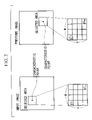
- FIG. 3 is an explanatory drawing showing processing for calculating the certainty CA of two characteristic points.
- FIG. 4 is an explanatory drawing showing a coordinate system in the case of determining the position of a robot.
- FIG. 5 is a block diagram showing the constitution of a second embodiment of the present invention.
- FIG. 6 is a flow chart showing the operations of characteristic point extraction unit 5 and position detection unit 6 shown in FIG. 5 .
- FIG. 7 is an explanatory drawing showing a method for calculating position.
- FIG. 8 is an explanatory drawing showing a method for calculating position.
- FIG. 9 is an explanatory drawing showing a method for calculating position.
- FIG. 10 is an explanatory drawing showing a status model of a Kalman filter.
- FIG. 11 is a block diagram showing the constitution of a third embodiment of the present invention.
- FIG. 12 is a flow chart showing the operation of the position detection apparatus shown in FIG. 11 .
- FIG. 13 is an explanatory drawing that explains the principle of position detection in the third embodiment.
- FIG. 14 is an explanatory drawing that explains the principle of position detection in the third embodiment.
- FIG. 15 is an explanatory drawing that explains the principle of position detection in the third embodiment.
- FIG. 1 is a block diagram showing the constitution of the present embodiment.
- the position detection apparatus shown in FIG. 1 is explained in the form of that equipped on an autonomous travel robot that moves indoors.
- reference symbol 1 represents two cameras that capture an object present in the field of view in the direction of movement during movement by the robot. These cameras are installed at a prescribed interval, and their mutual fields of view are aligned.
- Reference symbol 2 represents an image storage unit that respectively stores individual frames of images obtained by cameras 1 , and is composed of two frames of image memory.
- Reference symbol 3 represents a distance image formation unit that forms distance images from two frames of images stored in image storage unit 2 .
- Reference symbol 4 represents a distance image storage unit that stores the distance images formed in distance image formation unit 3 .
- Reference symbol 5 represents a characteristic point extraction unit that extracts characteristic points from images stored in image storage unit 2 or distance image storage unit 4 .
- Reference symbol 6 represents a position detection unit that detects self-position based on the results of characteristic point extraction in characteristic point extraction unit 5 .
- Reference symbol 7 represents a movement control unit that controls the movement of the robot by referring to the results of position detection by position detection unit 6 .
- distance image data is the set of three-dimensional coordinate values of a measurement point on the surface of an object in the field of view of cameras 1 .
- FIG. 2 is a flow chart showing the operation by which characteristic points are tracked continuously from brightness images stored in image storage unit 2 and distance images stored in distance image storage unit 4 by characteristic point extraction unit 5 and position detection unit 6 to detect self-position based on that position data.
- Each of the processing shown in the flow chart of FIG. 2 is executed repeatedly each time an image is captured by cameras 1 .
- the two cameras 1 operate as stereo cameras, and brightness images are captured with each camera which are then respectively stored in image storage unit 2 .
- distance image formation unit 3 forms a distance image by determining the corresponding points of the pixels of each image from the two brightness images acquired with two cameras 1 , which is then stored in distance image storage unit 4 .
- distance images are generated using so-called sub-pixels by interpolating between pixels in order to obtain more precise distance images with fewer pixels.
- the brightness and distance images of each pixel are expressed with 256 gradations.
- the pixels of distance images represent the distance to the surface of an object in the field of view of a sensor in 256 gradations.
- XYZ coordinates can be specified from a camera position to a single point on the surface of an object present in three-dimensional space according to the position of the pixels in a distance image.
- accuracy can be improved by using laser radar, milliwave radar or ultrasonic waves in place of the cameras.
- output values from the distance sensor may also be used directly without representing distance data in 256 gradations.
- Cameras 1 and distance image formation unit 3 execute this operation repeatedly.
- characteristic point extraction unit 5 reads images stored in image storage unit 2 (Step S 1 ).
- characteristic point extraction unit 5 extracts characteristic points from the brightness images that have been read, and stores these characteristic points in characteristic point extraction unit 5 (Step S 2 ).
- the characteristic points mentioned here refer to points equivalent to an unchanging characteristic amount used in image processing that characterize forms appearing in an image. Extraction of these characteristic points is performed by, for example, performing edge detection processing on brightness images and selecting those points that compose the detected edge.
- characteristic point extraction unit 5 may read distance images stored in distance image storage unit 4 , and then extract characteristic points from these distance images. Characteristic points are created using two consecutively incorporated brightness images. Here, their respective times are designated as “t” and “(t+1)”.
- characteristic point extraction brightness images obtained from either left or right camera 1 are used, and two types of characteristic points are stored consisting of a set of characteristic points extracted from the input image of time (t+1), and a set of characteristic points extracted from the image of time t immediately prior to the input image. Coordinate values on the image are stored for these characteristic points.
- position detection unit 6 reads a single input image characteristic point stored in characteristic point extraction unit 5 in order to determine the corresponding point of these characteristic points of two different times (Step S 3 ). Subsequently, position detection unit 6 reads one image point of the previous image stored in characteristic point extraction unit 5 (Step S 4 ).
- previous time t refers to the time at which Steps S 1 through S 17 presently being explained were performed previously, and the corresponding point between two different times t and (t+1) is obtained by Steps S 1 through S 17 being performed two times or more. Accordingly, when Steps S 1 through S 17 are performed for the first time, the process is extraordinarily executed through Step S 3 and then returns to Step S 1 .
- position detection unit 6 calculates the certainty CA of two characteristic points and performs pattern matching with the characteristic point stored at time t (Step S 5 ).
- m pixels ⁇ n pixels (provided m and n are natural numbers of 2 or more) around a characteristic point are selected for an input image from which a characteristic point has been extracted.
- m pixel ⁇ n pixels (provided m and n are natural numbers of 2 or more) around a characteristic point of the previous image are selected.
- the selected magnitude (m ⁇ n) of the pixels surrounding the two characteristic points may be determined arbitrarily, the number of selected pixels of the two characteristic points must be the same.
- position detection unit 6 compares certainty CA and threshold TC (Step S 6 ).
- displacement vector da is calculated from the coordinate value as the amount of characteristic point movement over a continuous period of time, and that vector da is then stored in position detection unit 6 (Step S 7 ).
- the process proceeds to Step S 8 .
- position detection unit 6 evaluates whether or not processing has been performed for all characteristic points of the previous image (Step S 8 ). If all of the characteristic points have not been processed, the process returns to Step S 4 and processing is repeated. On the other hand, if processing has been completed for all characteristic points of the previous image, position detection unit 6 evaluates whether or not processing has been performed for all characteristic points of the input image (Step S 9 ). If all of the characteristic points have not been processed, the operation returns to Step S 3 and processing is repeated. On the other hand, if processing has been completed for all characteristic points of the input image, the process proceeds to Step S 10 .
- results may be determined by calculating only the vicinities of the characteristic points to be determined in coordination with the required amount of movement in order to reduce the calculation processing load.
- position detection unit 6 reads the stored displacement vectors da and calculates the mean displacement vector Td (Step S 10 ).
- position detection unit 6 reads out the stored displacement vectors da one at atime (Step S 11 ).
- Position detection unit 6 then calculates
- position detection unit 6 judges the characteristic point used when calculating the relevant displacement vector da to be a stationary object (Step S 13 ).
- position detection unit 6 judges the characteristic point used when calculating the relevant displacement vector da to be a moving object (Step S 14 ). This processing is performed for all calculated displacement vectors da (Step S 15 ) and as a result, a judgment is made as to whether a characteristic point is a stationary object or moving object for each characteristic point.
- position detection unit 6 extracts those characteristic points judged to be stationary objects for which certainty CA is the superordinate (Step S 16 ).
- certainty CA being superordinate refers to certainty CA being superordinate the smaller the value of CA.
- Those characteristic points extracted by this extraction processing are characteristic points of a previous image (time t) that form a pair with characteristic points of the input image (time t+1), and these characteristic points serve as the reference characteristic points for calculation of self-position.
- position detection unit 6 determines characteristic point distance from the correlating points between each of the extracted reference characteristic points and the distance image stored in distance image storage unit 4 , and calculates the amount the robot moved from the time at which the previous image was acquired to the time at which the current image (input image) was acquired based on the amount of movement of that characteristic point and the relative position of the robot (Step S 17 ).
- the program returns again to Step S 1 and repeats the same processing on a characteristic point for which a correlation was previously obtained that has been stored in memory.
- the coordinate system here is a coordinate system defined when the robot is in the initial state, and the forward direction of the robot is designated as the X axis, while the direction that intersects this X axis is designated as the Y axis.
- a and b respectively represent arbitrary characteristic points such as columns located in a building that are extracted by the above processing.
- Data obtained by acquiring images by the robot consists of the relative position of characteristic point a (x a ,y a ) and the relative position of characteristic point b (x b ,y b ) shown in FIG. 4 .
- the symbol ⁇ here represents the angle of rotation of the robot about the Z axis, and is positive during counter-clockwise rotation.
- Robot angle of rotation ⁇ and robot position (x t ,y t ) can thus be determined according to the above.
- a and b were hypothesized to be known in the above explanation, since an unknown object is treated here, the absolute positions of a and b cannot be determined.
- the positions of a and b are determined based on the position of the robot at time t, and the displacement of robot position (amount of movement of the robot) is determined based on displacement da of the relative positions of a and b obtained at time t+1.
- robot position at time t+1 can then be determined.
- robot position can be easily determined based on the relative positions of a and b in the case a and b are known.
- the calculated position is notified to movement control unit 7 after which robot movement is controlled by movement control unit 7 based on this position.
- movement control unit 7 may be made to output position detection instructions to characteristic point extraction unit 5 so that characteristic point extraction unit 5 begins the processing shown in FIG. 2 upon receiving those position detection instructions.
- the displacement of the position of the stationary object can be determined over time, and the amount of self-movement can be determined each time from the amount of this displacement, thereby enabling self-position to be detected accurately.
- tracking may be performed by determining the history of movement of a characteristic point from two or more images and extracting stationary objects therefrom.
- robot position (x t+1 ,y t+1 ) can be determined by determining the target position from the target relative position and robot position (x t ,y t ) at time t based on the amount of displacement of the position of that target at time t+1.
- the position at time t+k can be similarly detected based on the amount of displacement of (x t+k ,y t+k ) during time k.
- distance image formation unit 3 shown in FIG. 1 may be replaced with radar and so forth using ultrasonic waves or electromagnetic waves. At this time, the measuring field of view of the radar is set to be the same as that of cameras 1 shown in FIG. 1 . In addition, in the case of obtaining distance images using radar and so forth, only a single camera 1 should be provided for obtaining brightness images.
- characteristic points may move outside the frame as the moving body approaches a characteristic point, thereby preventing detection of position. Consequently, characteristic points for which the amount of movement is calculated are successively switched by performing the processing shown in FIG. 2 on all of a plurality of characteristic points. In this case, however, since the error in measured distance increases as the characteristic point moves away from the moving body s compared with the case of approaching the moving body, if the amount of movement is made to be calculated by preferentially selecting the characteristic point within the frame that is at the shortest distance from the moving body, deterioration of movement accuracy can be prevented.
- tracking may also be performed such that the position of an object that has temporarily left the frame is stored in memory and then recognized as the same object when it again returns to inside the frame.
- FIG. 5 is a block diagram showing the constitution of another embodiment of the present invention.
- the block diagram shown in FIG. 5 is different from the block diagram shown in FIG. 1 with respect to newly providing object data storage unit 8 .
- This object data storage unit 8 stores sets of characteristic points of a plurality of known stationary objects in the form of a characteristic amount, and a map of objects corresponding to the absolute positions of those stationary objects, and is referred to by characteristic point extraction unit 5 and position detection unit 6 .
- Known stationary objects referred to here include such stationary objects as columns, plants, lockers and other articles of furniture in a room.
- the moving object can be controlled both efficiently and accurately.
- characteristic point extraction unit 5 reads an image stored in image storage unit 2 (Step S 21 ). Characteristic point extraction unit 5 then extracts characteristic points from the read brightness image and stores these characteristic points in characteristic point extraction unit 5 (Step S 22 ).
- the characteristic points referred to here are equivalent to an unchanging characteristic amount that is used in image processing that characterize forms appearing in an image.
- the characteristic amount refers to a plurality of groups of characteristic points that compose the object shape. Extraction of these characteristic points is performed by, for example, performing edge detection processing on an image and selecting a plurality of characteristic points that compose the detected edge.
- characteristic point extraction unit 5 may read distance images stored in distance image storage unit 4 , and then extract characteristic points from these distance images. Characteristic points are stored in the form of sets of characteristic points extracted from an image at time t (previous image), and these characteristic points are stored using their coordinate values on the image.
- characteristic point extraction unit 5 reads those characteristic points stored inside one at a time and compares them with the plurality of object data characteristic point groups (characteristic amount) stored in object data storage unit 8 by pattern matching (Step S 23 ).
- This comparison processing is performed by processing similar to the processing of the previously described embodiment (processing shown in FIG. 2 ).
- the object data referred to here indicates data comprised of the absolute coordinates of a position at which characteristic points and a stationary object are present after extracting the characteristic points of the stationary object from an image obtained in advance.
- a simple template matching method may be used for the pattern matching device used.
- characteristic point extraction unit 5 makes a judgment as to whether or not object data that coincides with or has a high degree of certainty, namely has a high correlation, with the characteristic point obtained in Step S 22 was present in object data storage unit 8 , or in other words, whether or not a known object was present (Step S 24 ).
- position detection unit 6 determines absolute self-position from this known stationary object and relative self-position (Step S 25 ). This absolute position is calculated from the absolute coordinates of the known object and the relationship between a known object obtained from a distance image stored in distance image storage unit 4 and relative self-position.
- characteristic point extraction unit 5 makes a judgment as to whether the characteristic point extracted in Step S 22 is a moving object or a stationary object (Step S 26 ).
- the respective absolute positions are determined from the relative positional relationship with self-position based on self-position data determined immediately before (Step S 27 ).
- This judgment processing is performed according to the processing of Steps S 4 through S 13 and S 14 shown in FIG. 2 .
- a judgment is then made as to whether the stationary object obtained as a result of this judgment processing could also have been tracked in the previous processing (time t) (Step S 28 ).
- This judgment is made by comparing the amount of consistency between the characteristic amount previously stored in object data storage unit 8 and the current characteristic amount by pattern matching.
- accuracy can be improved by comparing the absolute position of the characteristic amount previously stored in object data storage unit 8 in Step S 30 with the position determined Step S 27 , and adding a judgment that tracking could have been performed in the case they are in close proximity.
- position detection unit 6 determines absolute self-position from the relative positions of the stationary object and self-position (Step S 29 ).
- characteristic point extraction unit 5 determines the absolute position of the new characteristic point based on the characteristic point of a new stationary object and the absolute self-position at time t previously determined in Step S 25 or Step S 29 , and then stores that absolute position in object data storage unit 8 (Step S 30 ). Calculation of the amount of movement is performed according to the processing of Steps S 3 through S 17 shown in FIG. 2 .
- Step S 28 judgment of whether or not the positions are in close proximity is made by stipulating a distance threshold value and judging whether or not the previous position and current position are within this distance.
- statistical processing may also be performed. This may be performed by assuming that a certain characteristic amount could have been tracked for a continuous amount of time, calculating each of the variance values for the variance in relative position (x,y) with respect to self-position obtained from distance images for a position on an image of that characteristic amount, and judging those within the range of variance to be identical objects and those outside the range of variance to be different objects at the time the variance values converge.
- predefined variance values set in advance may be used, or predefined values may be used that have been set and stored for each object in object data storage unit 8 .
- a function may be used such that variance values are changed at the square of the distance.
- reference symbol AR indicates the action area
- origin G is determined in advance within this action area AR.
- Reference symbol R indicates a robot
- reference symbol K 4 a known stationary object
- reference symbol U 5 an unknown object. The angle of rotation ⁇ of robot R is ignored in FIG. 7 to simplify the explanation.
- Step S 28 the judgment of Step S 28 is made for all characteristic amounts, and in Step S 29 , self-position is determined from the relative positions with all characteristic amounts, after which self-absolute position is determined from the average value.
- movement control unit 7 is able to accurately control movement.
- Step S 23 objects K 1 , K 2 and K 3 , for which the absolute coordinates are known, are recognized to be present at point A.
- Position detection unit 6 determines absolute self-position from the coordinate values of the absolute positions of objects K 1 and K 2 since the distance of object K 3 among objects K 1 , K 2 and K 3 is the greatest (Step S 25 ).
- position detection unit 6 determines the coordinate values of unknown objects U 1 and U 2 by calculation, and stores those values in internal memory (Step S 30 ).
- the robot then moves while determining self-position based on the positions of unknown objects U 1 and U 2 for which the relative positions have become known (Step S 29 ), and in the case of reaching a position at which unknown objects U 1 and U 2 cannot be captured by the cameras, moves to point B while determining self-position based on known object K 3 (Step S 25 ) and finally determines the absolute position of point B.
- position data and object data relating to unknown objects U 1 and U 2 are updated.
- the robot changes direction and heads in the direction of point C.
- unknown objects U 3 and U 4 are captured by cameras 1 .
- self-position is determined by determining the amount of movement based on unknown objects U 3 and U 4 , and adding the determined amount of movement to the relative coordinate values of point B (Step S 29 ).
- absolute self-position is determined based on that known object, and the error in relative position determined according to the amount of movement is reset.
- robot position may be calculated using a Kalman filter based on extracted reference characteristic points. By using this Kalman filter, robot position can be calculated while taking into consideration variations in distance data and so forth.
- Equation (1) if the variables that express the status of the robot are represented with x, y, ⁇ and T, and defined as:
- the second term from the right is the amount of change in distance control at time t from movement control unit 7
- the third term represents the system noise associated with robot control at time t.
- the coordinate system used here is the same as that of FIG. 4 , while the meanings of each of the parameters that express the status of robot position are shown in FIG. 10 .
- Equation (2) is the observation equation of characteristic point a
- Equation (3) is the observation equation of characteristic point b.
- [ x a y a ⁇ a ] [ ( a x - x t ) ⁇ cos ⁇ ⁇ ( - ⁇ t ) - ( a y - y t ) ⁇ sin ⁇ ⁇ ( - ⁇ t ) ( a x - x t ) ⁇ sin ⁇ ⁇ ( - ⁇ t ) + ( a y - y t ) ⁇ cos ⁇ ⁇ ( - ⁇ t ) tan - 1 ⁇ ( E 2 E 1 ) ] + [ ⁇ ax ⁇ ay ⁇ a ⁇ ⁇ ⁇ ] ( 2 ) and
- [ x b y b ⁇ b ] [ ( b x - x t ) ⁇ cos ⁇ ⁇ ( - ⁇ t ) - ( b y - y t ) ⁇ sin ⁇ ⁇ ( - ⁇ t ) ( b x - x t ) ⁇ sin ⁇ ⁇ ( - ⁇ t ) + ( a y - y t ) ⁇ cos ⁇ ⁇ ( - ⁇ t ) tan - 1 ⁇ ( E 4 E 3 ) ] + [ ⁇ bx ⁇ by ⁇ b ⁇ ⁇ ] ( 3 )
- E 1 ( a x ⁇ x t ) cos ( ⁇ t ) ⁇ ( a y ⁇ y t ) sin ( ⁇ t )
- E 2 ( a x ⁇ x t ) sin ( ⁇ t )+( a y ⁇ y t ) cos ( ⁇ t )
- E 3 ( b x ⁇ x t ) cos ( ⁇ t ) ⁇ ( b y ⁇ y t ) sin ( ⁇ t )
- E 4 ( b x ⁇ x t ) sin ( ⁇ t )+( b y ⁇ y t ) cos ( ⁇ t ),
- Equation (2) the second term on the right side in Equations (2) and (3) represents noise.
- Equations (1) through (3) are used in the processing of Steps S 25 and S 29 shown in FIG. 6 .
- robot angle of rotation ⁇ t+1 and robot position (x t+1 , y t+1 ) can be determined.
- robot position can be detected more accurately since both system noise and measurement noise are taken into consideration as compared with calculating geometrically as described above.
- the covariance of observed values relative to characteristic points that converges within the Kalman filter can be used as the variance values of those characteristic points.
- self-position may also be determined to include height by expanding to the direction of height (z direction).
- FIG. 11 is a block diagram indicating the constitution of a position detection apparatus in a third embodiment.
- reference symbol 1 indicates a camera
- reference symbol 5 indicates a characteristic point extraction unit.
- Reference symbol 8 indicates an object data storage unit.
- Reference symbol 9 indicates a correlation processing unit that determines the correlation between two characteristic points.
- Reference symbol 10 indicates a self-position determination unit that determines self-position based on the processing results of correlation processing unit 9 .
- image storage unit 2 which stores obtained images, and movement control unit 7 are omitted.
- related constituents are deleted.
- FIG. 13 depicts a scene in the forward direction F ⁇ of the robot at position M being captured with the camera followed by selection of characteristic point groups from the resulting image.
- characteristic point groups W are correlated with position M and stored in object data storage unit 8 . Since the characteristic point groups here do not allow identification of their respective relative positions due to occlusion and so forth, stored positions are correlated for all characteristic points.
- FIG. 14 indicates the example of there being 9 positions at which characteristic point groups are stored in memory (M 1 through M 9 ), these positions being preset at positions over which the robot is likely to pass. If characteristic point groups extracted from an image captured with a camera facing in the direction of forward direction F ⁇ of the robot from each preset position M 1 through M 9 are designated as W 1 through W 9 , each position (referred to as a characteristic point acquisition position) M 1 through M 9 and characteristic point groups W 1 through W 9 are correlated into respective pairs which are then stored in advance in object data storage unit 8 .
- the correlation between the characteristic point groups extracted from the image captured with the camera facing in the direction of forward direction F ⁇ and pre-stored characteristic point groups W 1 through W 9 is determined, and characteristic point group Wn (where n is any of 1 through 9 ) having the highest correlation is judged to be the position over which the robot is passing, and the characteristic point acquisition position Mn (where n is any of 1 through 9 ) that forms a pair with this characteristic point group Wn becomes the self-position.
- position M 4 at which this characteristic point group W 4 was acquired is determined to be the self-position.
- characteristic point extraction unit 5 reads an image captured with camera 1 (Step S 41 ). Characteristic point extraction unit 5 then extracts all characteristic point groups from the read image and stores them in internal memory (Step S 42 ). On the other hand, correlation processing unit 9 reads one characteristic point group stored in object data storage unit 8 (Step S 43 ). Continuing, correlation processing unit 9 reads one characteristic point of the input image (image captured with camera 1 ) from characteristic point extraction unit 5 (Step S 44 ). Moreover, correlation processing unit 9 selects one characteristic point from the characteristic point group read in Step S 43 (Step S 45 ).
- correlation processing unit 9 calculates the certainty CA between the characteristic point read in Step S 44 and the characteristic point selected in Step S 45 (Step S 46 ), and compares this with a predetermined threshold value Tc (Step S 47 ). As a result, the program proceeds to Step S 49 unless CA>Tc. On the other hand, if CA>Tc, the sum S of CA determined for each processing loop is determined (Step S 48 ). Since the sum S of CA is determined for each characteristic point group, however, sum S of certainty CA is obtained for the number of characteristic point groups only. Correlation processing unit 9 then repeats the processing of Steps S 45 through S 48 for all characteristic points that compose the characteristic point group read in Step S 43 (Step S 49 ).
- correlation processing unit 9 repeats the processing of Steps S 44 through S 48 for all characteristic points that compose the characteristic point groups stored in Step S 42 (Step S 50 ), and then repeats the processing of Steps S 43 through S 48 for all the characteristic point groups stored in Step S 42 (Step S 51 ).
- the processing of Steps S 42 through S 48 consists of determining the certainty for all of the characteristic points that compose the characteristic point groups extracted from the input image as well as all of the characteristic points stored in object data storage unit 8 . Furthermore, in the processing of Steps S 44 through S 50 , the processing load can be reduced by determine certainty after selecting those characteristic points in close proximity to the image pixels.
- self-position determination unit 10 selects the characteristic point group for which the sum S of certainty CA determined in Step 48 is largest (Step 552 ). Self-position is then determined by reading the characteristic point acquisition position that forms a pair with the selected characteristic point group from object data storage unit 8 (Step 553 ) followed by output of that position as self-position data.
- two left and right cameras that compose a stereo camera of the robot may be used to compare a pre-stored characteristic point group W for each camera and arithmetically determine correlation.
- self-position can be determined according to the difference in the magnitudes of the degree of correlation of the camera images relative to the same characteristic point group W.
- the direction of offset to the left and right of position M can be detected from the difference in correlation values detected with each camera relative to position M corresponding to characteristic point group W. Consequently, since the number in the left and right directions of position M at which the characteristic point group is obtained can be reduced, the bother associated with capturing an image in advance can be reduced considerably.
- they should be used by selecting cameras arranged in the left and right directions.
- FIGS. 13 and 14 were explained assuming a single direction for the direction of image capturing at each position M 1 through M 9 , if images in a plurality of directions are captured at each position, characteristic point groups are extracted for all resulting images, and those characteristic point groups are stored in object data storage unit 8 , self-position can be detected by the same processing even if the forward direction of the robot differs at each position.
- the robot may also be made to extract characteristic point groups from enlarged or reduced images by using a zoom function of the camera equipped on the robot itself. If this is done, it becomes easier to obtain a correlation in a case such as when the robot is positioned between positions M 2 and M 5 shown in FIG. 14 .
- the robot may also be made to extract characteristic point groups from images obtained in a state in which a head unit equipped with a camera swings horizontally and vertically. When this is done, it becomes easy to obtain a correlation between characteristic points even in cases in which the robot is acting in a direction different from the forward direction when it acquired a stored characteristic point group.
- position detection processing previously described in the three embodiments may be suitably combined corresponding to the environment in which the robot moves, and self-position may be detected by selecting the necessary processing.
- a program for realizing the processing shown in FIGS. 2 , 6 and 12 may be recorded on a recording medium that can be read by a computer, the program recorded on the recording medium may be loaded into a computer system, and that program may then be run to perform position detection processing.
- the “computer system” referred to here includes an OS, peripherals and other hardware.
- the “computer system” also includes a web site providing environment (or display environment).
- a “recording medium that can be read by a computer” refers to a flexible disc, magneto-optical disc, ROM, CD-ROM or other portable media as well as a storage device such as a hard disk built into the computer system.
- the “recording medium that can be read by a computer” also includes that which retains a program for a fixed amount of time in the manner of non-volatile memory (RAM) inside a computer system comprised of a server and clients in the case the program is transmitted via the Internet or other network or via a telephone line or other communication line.
- RAM non-volatile memory
- the above program may be transferred to another computer system via a transfer medium or by a transfer wave within a transfer medium from a computer system that contains the program in a storage device and so forth.
- the “transfer medium” that transfers the program refers to a medium having a function for transferring information in the manner of the Internet or other network or a telephone line or other communication line.
- the above program may also be that for realizing a portion of the functions described above.
- it may also be that which realizes the above functions by combining with a program already stored in a computer system in the form of a so-called differential file (differential program).
- the present invention offers the advantage of being able to accurately detect self-position.
- extraction of the stationary object can be performed independently, the constitution can be simplified since it is not necessary to provide a map and so forth in which the positions of stationary objects have been defined in advance.
- the present invention is particularly suited to a humanoid robot that moves by the use of legs.
- the present invention offers the advantage of being able to detect self-position more accurately.
- the present invention offers the advantage of being able to detect self-position more accurately.
- the present invention offers the advantage of enabling updating of map data and object data to be performed automatically.
Abstract
Description
tan−1(a y /a x)−tan−1(y a /x a)=φ
In addition, the following equation is determined with respect to b:
tan−1(b y /b x)−tan−1(y b /x b)=φ
then xt and yt are the x and y values on the x and y axes, φt is the angle of rotation about the z axis, and Tt is the distance when moving from time step t to time step (t+1).
In Equation (1), the second term from the right is the amount of change in distance control at time t from movement control unit 7, while the third term represents the system noise associated with robot control at time t. The coordinate system used here is the same as that of
in defined, then
becomes
and
becomes
E 1=(a x −x t) cos (−φt)−(a y −y t) sin (−φt),
E 2=(a x −x t) sin (−φt)+(a y −y t) cos (−φt),
E 3=(b x −x t) cos (−φt)−(b y −y t) sin (−φt),
E 4=(b x −x t) sin (−φt)+(b y −y t) cos (−φt),
Claims (22)
Applications Claiming Priority (3)
| Application Number | Priority Date | Filing Date | Title |
|---|---|---|---|
| JP2000157299 | 2000-05-26 | ||
| JP2000-157299 | 2000-05-26 | ||
| JP2001124943A JP4672175B2 (en) | 2000-05-26 | 2001-04-23 | Position detection apparatus, position detection method, and position detection program |
Publications (2)
| Publication Number | Publication Date |
|---|---|
| US20010055063A1 US20010055063A1 (en) | 2001-12-27 |
| US7239339B2 true US7239339B2 (en) | 2007-07-03 |
Family
ID=26592745
Family Applications (1)
| Application Number | Title | Priority Date | Filing Date |
|---|---|---|---|
| US09/866,151 Expired - Lifetime US7239339B2 (en) | 2000-05-26 | 2001-05-26 | Position detection apparatus, position detection method and position detection program |
Country Status (3)
| Country | Link |
|---|---|
| US (1) | US7239339B2 (en) |
| EP (1) | EP1158309B1 (en) |
| JP (1) | JP4672175B2 (en) |
Cited By (8)
| Publication number | Priority date | Publication date | Assignee | Title |
|---|---|---|---|---|
| US20050181527A1 (en) * | 2002-07-22 | 2005-08-18 | Sumitomo Electric Industries, Ltd., A Osaka, Japan Corporation | Method for forming scribed groove and scribing apparatus |
| DE102008024308A1 (en) * | 2008-05-20 | 2009-12-03 | Eads Deutschland Gmbh | Method for detecting non-cooperative air traffic on-board of aircraft, involves calculating distance or position of target on both blades of aircraft from angles by two sensors |
| US20100235033A1 (en) * | 2006-09-11 | 2010-09-16 | Kenjiro Yamamoto | Moving device |
| US20130108172A1 (en) * | 2010-05-19 | 2013-05-02 | Tokyo Institute Of Technology | Position Estimation Device, Position Estimation Method, And Program |
| US20130148849A1 (en) * | 2011-12-07 | 2013-06-13 | Fujitsu Limited | Image processing device and method |
| US20140015998A1 (en) * | 2011-03-28 | 2014-01-16 | Nec Corporation | Image capture position and image capture direction estimation device, image capture device, image capture position and image capture direction estimation method and program |
| US20140236477A1 (en) * | 2013-02-15 | 2014-08-21 | Caterpillar Inc. | Positioning system utilizing enhanced perception-based localization |
| US9738399B2 (en) * | 2015-07-29 | 2017-08-22 | Hon Hai Precision Industry Co., Ltd. | Unmanned aerial vehicle control method and unmanned aerial vehicle using same |
Families Citing this family (85)
| Publication number | Priority date | Publication date | Assignee | Title |
|---|---|---|---|---|
| JP2004061446A (en) * | 2002-07-31 | 2004-02-26 | Fujitsu Ten Ltd | Pattern matching processing method and image processor |
| EP1413974A1 (en) * | 2002-10-24 | 2004-04-28 | Hewlett-Packard Company | Hybrid sensing techniques for position determination |
| JP4171282B2 (en) * | 2002-10-25 | 2008-10-22 | 富士重工業株式会社 | Terrain recognition device and terrain recognition method |
| EP2418458B1 (en) * | 2003-09-19 | 2017-03-15 | Omron Corporation | Multiple sensor system |
| KR100540194B1 (en) * | 2003-09-23 | 2006-01-10 | 한국전자통신연구원 | Establishment System of RFID Tag Using Vehicle and Method Using It |
| US20080243321A1 (en) | 2005-02-11 | 2008-10-02 | Econtrols, Inc. | Event sensor |
| US9052717B1 (en) | 2004-02-11 | 2015-06-09 | Enovation Controls, Llc | Watercraft speed control device |
| JP3879740B2 (en) * | 2004-02-13 | 2007-02-14 | 日産自動車株式会社 | Road area detection device |
| JP2005249715A (en) * | 2004-03-08 | 2005-09-15 | Topcon Corp | Survey method and survey instrument |
| KR100763234B1 (en) * | 2004-06-11 | 2007-10-04 | 삼성전자주식회사 | System and method for detecting a state of travelling |
| JP4216772B2 (en) * | 2004-06-17 | 2009-01-28 | 株式会社東芝 | Self-position identification device and self-position identification method |
| EP1759334A2 (en) * | 2004-06-22 | 2007-03-07 | Sarnoff Corporation | Method and apparatus for visual odometry |
| JP4488804B2 (en) * | 2004-06-23 | 2010-06-23 | 株式会社トプコン | Stereo image association method and three-dimensional data creation apparatus |
| CN101065785B (en) * | 2004-08-30 | 2013-01-23 | 联邦科学和工业研究组织 | A method for automated 3D imaging |
| KR100569472B1 (en) * | 2004-10-05 | 2006-04-07 | 현대자동차주식회사 | Fuel spray tip velocity measuring apparatus and method in an engine |
| US8000837B2 (en) | 2004-10-05 | 2011-08-16 | J&L Group International, Llc | Programmable load forming system, components thereof, and methods of use |
| US9207675B1 (en) * | 2005-02-11 | 2015-12-08 | Enovation Controls, Llc | Event sensor |
| KR100638220B1 (en) * | 2005-04-23 | 2006-10-27 | 엘지전자 주식회사 | Position sensing device of mobile robot and robot cleaner equipped with it |
| US8306662B2 (en) | 2005-04-23 | 2012-11-06 | Lg Electronics Inc. | Position detection device for mobile robot and robot cleaner including the same |
| DE102005035746B4 (en) * | 2005-07-29 | 2010-02-18 | Siemens Ag | Method for determining a relative position of a mobile unit by comparing scans of an environment and mobile unit |
| JP2007094743A (en) * | 2005-09-28 | 2007-04-12 | Zmp:Kk | Autonomous mobile robot and system therefor |
| JP2007114020A (en) * | 2005-10-19 | 2007-05-10 | Aisin Aw Co Ltd | Vehicle moving distance detecting method and device, and current vehicle position detecting method and device |
| CN100419605C (en) * | 2005-11-09 | 2008-09-17 | 沈阳新松机器人自动化股份有限公司 | Control apparatus for position of field bus |
| CN101200065B (en) * | 2006-12-13 | 2010-10-06 | 沈阳新松机器人自动化股份有限公司 | Site bus position controller |
| KR100912874B1 (en) | 2007-06-28 | 2009-08-19 | 삼성전자주식회사 | Method and apparatus for relocating a mobile robot |
| KR100884904B1 (en) * | 2007-09-12 | 2009-02-19 | 아주대학교산학협력단 | Method for self localization using parallel projection model |
| US8264537B2 (en) * | 2007-09-28 | 2012-09-11 | The Mainz Group Llc | Photogrammetric networks for positional accuracy |
| JP2009115621A (en) * | 2007-11-06 | 2009-05-28 | Toshiba Corp | Mobile image tracking device |
| JP4337929B2 (en) | 2007-12-25 | 2009-09-30 | トヨタ自動車株式会社 | Moving state estimation device |
| JP5349804B2 (en) * | 2008-01-10 | 2013-11-20 | 株式会社日立産機システム | Mobile robot system and control method thereof |
| DE102008039606A1 (en) * | 2008-08-25 | 2010-03-04 | GM Global Technology Operations, Inc., Detroit | Motor vehicle with a distance sensor and an image acquisition system |
| JP5409189B2 (en) * | 2008-08-29 | 2014-02-05 | キヤノン株式会社 | Imaging apparatus and control method thereof |
| KR101022785B1 (en) * | 2008-09-17 | 2011-03-17 | 포항공과대학교 산학협력단 | mapping method for circumstances of robot using a nerve network and evolutionary computation |
| KR101038702B1 (en) | 2008-10-24 | 2011-06-03 | 전자부품연구원 | Method for detecting position of robot |
| JP4816748B2 (en) * | 2009-03-06 | 2011-11-16 | ソニー株式会社 | Navigation device and navigation method |
| JP5278878B2 (en) * | 2009-03-23 | 2013-09-04 | 国立大学法人 宮崎大学 | Pipe inner surface shape measuring device |
| JP4810582B2 (en) * | 2009-03-26 | 2011-11-09 | 株式会社東芝 | Mobile object image tracking apparatus and method |
| WO2011163454A1 (en) | 2010-06-25 | 2011-12-29 | Trimble Navigation Ltd. | Method and apparatus for image-based positioning |
| US8963954B2 (en) * | 2010-06-30 | 2015-02-24 | Nokia Corporation | Methods, apparatuses and computer program products for providing a constant level of information in augmented reality |
| JP2012034196A (en) * | 2010-07-30 | 2012-02-16 | Olympus Corp | Imaging terminal, data processing terminal, imaging method, and data processing method |
| JP5690539B2 (en) | 2010-09-28 | 2015-03-25 | 株式会社トプコン | Automatic take-off and landing system |
| JP5618840B2 (en) | 2011-01-04 | 2014-11-05 | 株式会社トプコン | Aircraft flight control system |
| JP5775354B2 (en) | 2011-04-28 | 2015-09-09 | 株式会社トプコン | Takeoff and landing target device and automatic takeoff and landing system |
| JP5787695B2 (en) | 2011-09-28 | 2015-09-30 | 株式会社トプコン | Image acquisition device |
| JP5947016B2 (en) * | 2011-10-26 | 2016-07-06 | 株式会社ディスコ | Key pattern determination method |
| JP5802279B2 (en) | 2011-11-22 | 2015-10-28 | 株式会社日立製作所 | Autonomous mobile system |
| US20140039675A1 (en) * | 2012-08-03 | 2014-02-06 | Nimer Mohammed Ead | Instructional humanoid robot apparatus and a method thereof |
| JP6015250B2 (en) * | 2012-08-31 | 2016-10-26 | 富士通株式会社 | Image processing apparatus, image processing method, and image processing program |
| US9036865B2 (en) * | 2012-09-12 | 2015-05-19 | International Business Machines Corporation | Location determination for an object using visual data |
| WO2014073204A1 (en) * | 2012-11-06 | 2014-05-15 | 国立大学法人東京工業大学 | Feature value extraction device and location inference device |
| US9560246B2 (en) * | 2012-12-14 | 2017-01-31 | The Trustees Of Columbia University In The City Of New York | Displacement monitoring system having vibration cancellation capabilities |
| JP6094279B2 (en) * | 2013-03-14 | 2017-03-15 | 株式会社国際電気通信基礎技術研究所 | TRACKING DEVICE, TRACKING PROGRAM, AND TRACKING METHOD |
| US9081382B2 (en) | 2013-03-15 | 2015-07-14 | Fresenius Medical Care Holdings, Inc. | Autonomous vehicle comprising extracorporeal blood treatment machine |
| US20160238394A1 (en) * | 2013-10-01 | 2016-08-18 | Hitachi, Ltd.. | Device for Estimating Position of Moving Body and Method for Estimating Position of Moving Body |
| TWI534453B (en) * | 2014-02-18 | 2016-05-21 | 原相科技股份有限公司 | Relative position positioning system and tracking system |
| WO2015129152A1 (en) * | 2014-02-26 | 2015-09-03 | 株式会社ソシオネクスト | Image recognition system and semiconductor integrated circuit |
| US10310054B2 (en) * | 2014-03-21 | 2019-06-04 | The Boeing Company | Relative object localization process for local positioning system |
| GB201409625D0 (en) * | 2014-05-30 | 2014-07-16 | Isis Innovation | Vehicle localisation |
| FR3022036B1 (en) * | 2014-06-05 | 2016-07-15 | Aldebaran Robotics | CROSS-PLAN DETECTION DEVICE OF AN OBSTACLE AND DETECTION METHOD USING SAME |
| DE102014212781A1 (en) | 2014-07-02 | 2016-01-07 | Continental Automotive Gmbh | Method for determining and providing a landmark for determining the position of a vehicle |
| JP6369897B2 (en) * | 2014-08-07 | 2018-08-08 | 日産自動車株式会社 | Self-position calculation device and self-position calculation method |
| JP6369898B2 (en) * | 2014-08-07 | 2018-08-08 | 日産自動車株式会社 | Self-position calculation device and self-position calculation method |
| US10339389B2 (en) * | 2014-09-03 | 2019-07-02 | Sharp Laboratories Of America, Inc. | Methods and systems for vision-based motion estimation |
| JP6352133B2 (en) * | 2014-09-26 | 2018-07-04 | 株式会社Screenホールディングス | Position detection apparatus, substrate processing apparatus, position detection method, and substrate processing method |
| ES2788479T3 (en) | 2015-06-26 | 2020-10-21 | Sz Dji Technology Co Ltd | System and method to measure a displacement of a mobile platform |
| JP6556015B2 (en) * | 2015-10-09 | 2019-08-07 | ソニー株式会社 | Information processing apparatus, position and / or orientation estimation method, and computer program |
| CN116883522A (en) * | 2015-12-14 | 2023-10-13 | 松下电器(美国)知识产权公司 | Three-dimensional data encoding method, decoding method, encoding device, and decoding device |
| JP6864433B2 (en) * | 2016-01-29 | 2021-04-28 | 東芝ライフスタイル株式会社 | Vacuum cleaner |
| JP6626410B2 (en) | 2016-06-03 | 2019-12-25 | 株式会社Soken | Vehicle position specifying device and vehicle position specifying method |
| JP2018051728A (en) * | 2016-09-30 | 2018-04-05 | ファナック株式会社 | Detection method and detection apparatus for detecting three-dimensional position of object |
| JP6803745B2 (en) * | 2016-12-28 | 2020-12-23 | 日立Geニュークリア・エナジー株式会社 | Inspection equipment |
| US11457158B2 (en) | 2017-07-27 | 2022-09-27 | Nec Corporation | Location estimation device, location estimation method, and program recording medium |
| US10440280B2 (en) * | 2017-09-21 | 2019-10-08 | Advanced Semiconductor Engineering, Inc. | Optical system and method for operating the same |
| US11822341B2 (en) | 2017-12-28 | 2023-11-21 | Sony Corporation | Control device, control method, and mobile object to estimate the mobile object's self-position |
| CN108900805B (en) * | 2018-07-11 | 2021-01-12 | 长沙理工大学 | Computer network-based mobile real-time monitoring system for art design supplies |
| CN109358315B (en) * | 2018-10-12 | 2020-08-18 | 华中科技大学 | Auxiliary target indirect positioning method and system |
| KR102593422B1 (en) | 2018-10-17 | 2023-10-26 | 현대모비스 주식회사 | Backward driving assist apparatus of vehicle and control method thereof |
| KR102356469B1 (en) * | 2018-10-17 | 2022-01-28 | 현대모비스 주식회사 | Backward driving assist apparatus and method of vehicle |
| WO2020133175A1 (en) * | 2018-12-28 | 2020-07-02 | Intel Corporation | Tracking objects using sensor rotation |
| US11347226B2 (en) * | 2019-04-25 | 2022-05-31 | Lg Electronics Inc. | Method of redefining position of robot using artificial intelligence and robot of implementing thereof |
| CN113711273A (en) * | 2019-04-25 | 2021-11-26 | 三菱电机株式会社 | Motion amount estimation device, motion amount estimation method, and motion amount estimation program |
| JP7180739B2 (en) * | 2019-06-19 | 2022-11-30 | 株式会社リコー | Information processing device, information processing system, information processing method and information processing program |
| CN110653837B (en) * | 2019-10-31 | 2021-08-13 | 灵动科技(北京)有限公司 | Autonomous moving device and warehouse logistics system |
| KR102252888B1 (en) * | 2020-01-03 | 2021-05-17 | 포테닛 주식회사 | An apparatus and method for detecting position of transfer robot in space |
| CN112025697B (en) * | 2020-07-10 | 2022-06-17 | 浙江工业大学 | Integral model prediction control method of omnidirectional mobile robot |
Citations (10)
| Publication number | Priority date | Publication date | Assignee | Title |
|---|---|---|---|---|
| GB2116000A (en) | 1982-03-02 | 1983-09-14 | Elliott Bros | Guidance system |
| US5051906A (en) | 1989-06-07 | 1991-09-24 | Transitions Research Corporation | Mobile robot navigation employing retroreflective ceiling features |
| US5525882A (en) * | 1993-10-25 | 1996-06-11 | International Business Machines Corporation | Method and system for maneuvering a mobile robot |
| US5777690A (en) | 1995-01-20 | 1998-07-07 | Kabushiki Kaisha Toshiba | Device and method for detection of moving obstacles |
| US5819016A (en) * | 1993-10-05 | 1998-10-06 | Kabushiki Kaisha Toshiba | Apparatus for modeling three dimensional information |
| EP0892278A2 (en) | 1997-07-15 | 1999-01-20 | Forsvarets Forskningsinstitutt | Navigation system |
| WO1999053335A1 (en) | 1998-04-15 | 1999-10-21 | Commonwealth Scientific And Industrial Research Organisation | Method of tracking and sensing position of objects |
| US6148250A (en) * | 1998-02-18 | 2000-11-14 | Fuji Jukogyo Kabushiki Kaisha | Altitude detection by use of planar approximation of a region of ground surface |
| US6477260B1 (en) * | 1998-11-02 | 2002-11-05 | Nissan Motor Co., Ltd. | Position measuring apparatus using a pair of electronic cameras |
| US6678394B1 (en) * | 1999-11-30 | 2004-01-13 | Cognex Technology And Investment Corporation | Obstacle detection system |
Family Cites Families (8)
| Publication number | Priority date | Publication date | Assignee | Title |
|---|---|---|---|---|
| JPH0820253B2 (en) * | 1986-11-27 | 1996-03-04 | 神鋼電機株式会社 | Position detection method in mobile robot |
| JP3555159B2 (en) * | 1994-03-02 | 2004-08-18 | 日本電気株式会社 | Three-dimensional shape restoration method and apparatus |
| JPH0843055A (en) * | 1994-07-29 | 1996-02-16 | Canon Inc | Method and apparatus for recognizing shape of three dimensional object |
| JPH0933247A (en) * | 1995-07-19 | 1997-02-07 | Mitsubishi Electric Corp | Image object detecting apparatus |
| JPH0953939A (en) * | 1995-08-18 | 1997-02-25 | Fujitsu Ltd | Method and system for measuring position of mobile vehicle |
| JPH10222665A (en) * | 1997-01-31 | 1998-08-21 | Fujitsu Ten Ltd | Picture recognizing device |
| SE511504C2 (en) * | 1997-10-17 | 1999-10-11 | Apogeum Ab | Method and apparatus for associating anonymous reflectors to detected angular positions |
| JP4005679B2 (en) * | 1997-11-19 | 2007-11-07 | 富士重工業株式会社 | Ambient environment recognition device for autonomous vehicles |
-
2001
- 2001-04-23 JP JP2001124943A patent/JP4672175B2/en not_active Expired - Fee Related
- 2001-05-23 EP EP01112618.2A patent/EP1158309B1/en not_active Expired - Lifetime
- 2001-05-26 US US09/866,151 patent/US7239339B2/en not_active Expired - Lifetime
Patent Citations (10)
| Publication number | Priority date | Publication date | Assignee | Title |
|---|---|---|---|---|
| GB2116000A (en) | 1982-03-02 | 1983-09-14 | Elliott Bros | Guidance system |
| US5051906A (en) | 1989-06-07 | 1991-09-24 | Transitions Research Corporation | Mobile robot navigation employing retroreflective ceiling features |
| US5819016A (en) * | 1993-10-05 | 1998-10-06 | Kabushiki Kaisha Toshiba | Apparatus for modeling three dimensional information |
| US5525882A (en) * | 1993-10-25 | 1996-06-11 | International Business Machines Corporation | Method and system for maneuvering a mobile robot |
| US5777690A (en) | 1995-01-20 | 1998-07-07 | Kabushiki Kaisha Toshiba | Device and method for detection of moving obstacles |
| EP0892278A2 (en) | 1997-07-15 | 1999-01-20 | Forsvarets Forskningsinstitutt | Navigation system |
| US6148250A (en) * | 1998-02-18 | 2000-11-14 | Fuji Jukogyo Kabushiki Kaisha | Altitude detection by use of planar approximation of a region of ground surface |
| WO1999053335A1 (en) | 1998-04-15 | 1999-10-21 | Commonwealth Scientific And Industrial Research Organisation | Method of tracking and sensing position of objects |
| US6477260B1 (en) * | 1998-11-02 | 2002-11-05 | Nissan Motor Co., Ltd. | Position measuring apparatus using a pair of electronic cameras |
| US6678394B1 (en) * | 1999-11-30 | 2004-01-13 | Cognex Technology And Investment Corporation | Obstacle detection system |
Non-Patent Citations (2)
| Title |
|---|
| Chenavier F et al., Position Estimation for a Mobile Robot Using Vision and Odometry May 12, 1992 pp. 2588-2593. |
| Kokichi Sugihara, Some Location Problems for Robot Navigation Using a Single Camers Apr. 1, 1988 pp. 112-129. |
Cited By (14)
| Publication number | Priority date | Publication date | Assignee | Title |
|---|---|---|---|---|
| US20050181527A1 (en) * | 2002-07-22 | 2005-08-18 | Sumitomo Electric Industries, Ltd., A Osaka, Japan Corporation | Method for forming scribed groove and scribing apparatus |
| US20100235033A1 (en) * | 2006-09-11 | 2010-09-16 | Kenjiro Yamamoto | Moving device |
| US8239084B2 (en) * | 2006-09-11 | 2012-08-07 | Hitachi, Ltd. | Moving device |
| DE102008024308A1 (en) * | 2008-05-20 | 2009-12-03 | Eads Deutschland Gmbh | Method for detecting non-cooperative air traffic on-board of aircraft, involves calculating distance or position of target on both blades of aircraft from angles by two sensors |
| DE102008024308B4 (en) * | 2008-05-20 | 2010-12-09 | Eads Deutschland Gmbh | Method for detecting non-cooperative aviation on board an aircraft |
| US9098744B2 (en) * | 2010-05-19 | 2015-08-04 | Tokyo Institute Of Technology | Position estimation device, position estimation method, and program |
| US20130108172A1 (en) * | 2010-05-19 | 2013-05-02 | Tokyo Institute Of Technology | Position Estimation Device, Position Estimation Method, And Program |
| US20140015998A1 (en) * | 2011-03-28 | 2014-01-16 | Nec Corporation | Image capture position and image capture direction estimation device, image capture device, image capture position and image capture direction estimation method and program |
| US9232128B2 (en) * | 2011-03-28 | 2016-01-05 | Nec Corporation | Image capture position and image capture direction estimation device, image capture device, image capture position and image capture direction estimation method and program |
| US20130148849A1 (en) * | 2011-12-07 | 2013-06-13 | Fujitsu Limited | Image processing device and method |
| US9213897B2 (en) * | 2011-12-07 | 2015-12-15 | Fujitsu Limited | Image processing device and method |
| US20140236477A1 (en) * | 2013-02-15 | 2014-08-21 | Caterpillar Inc. | Positioning system utilizing enhanced perception-based localization |
| US9142063B2 (en) * | 2013-02-15 | 2015-09-22 | Caterpillar Inc. | Positioning system utilizing enhanced perception-based localization |
| US9738399B2 (en) * | 2015-07-29 | 2017-08-22 | Hon Hai Precision Industry Co., Ltd. | Unmanned aerial vehicle control method and unmanned aerial vehicle using same |
Also Published As
| Publication number | Publication date |
|---|---|
| JP2002048513A (en) | 2002-02-15 |
| JP4672175B2 (en) | 2011-04-20 |
| EP1158309A3 (en) | 2005-02-09 |
| EP1158309A2 (en) | 2001-11-28 |
| US20010055063A1 (en) | 2001-12-27 |
| EP1158309B1 (en) | 2013-08-21 |
Similar Documents
| Publication | Publication Date | Title |
|---|---|---|
| US7239339B2 (en) | Position detection apparatus, position detection method and position detection program | |
| JP5148669B2 (en) | Position detection apparatus, position detection method, and position detection program | |
| US7333631B2 (en) | Landmark, apparatus, and method for effectively determining position of autonomous vehicles | |
| US8024072B2 (en) | Method for self-localization of robot based on object recognition and environment information around recognized object | |
| US10636168B2 (en) | Image processing apparatus, method, and program | |
| Jang et al. | Color landmark based self-localization for indoor mobile robots | |
| US8792726B2 (en) | Geometric feature extracting device, geometric feature extracting method, storage medium, three-dimensional measurement apparatus, and object recognition apparatus | |
| Gonzalez et al. | Combined visual odometry and visual compass for off-road mobile robots localization | |
| Nair et al. | Moving obstacle detection from a navigating robot | |
| CN110967711A (en) | Data acquisition method and system | |
| US5422828A (en) | Method and system for image-sequence-based target tracking and range estimation | |
| JP4429461B2 (en) | Image processing apparatus, plane detection method, and recording medium recording plane detection program | |
| Iocchi et al. | Self-localization in the RoboCup environment | |
| Wolf et al. | Using an image retrieval system for vision-based mobile robot localization | |
| Xian et al. | Fusing stereo camera and low-cost inertial measurement unit for autonomous navigation in a tightly-coupled approach | |
| Spacek et al. | Instantaneous robot self-localization and motion estimation with omnidirectional vision | |
| Alves et al. | Cost-effective indoor localization for autonomous robots using kinect and wifi sensors | |
| Fitzgibbons et al. | Application of vision in simultaneous localization and mapping | |
| Ferreira et al. | A comparison between different feature-based methods for ROV vision-based speed estimation | |
| Werner et al. | Visual topological mapping and localisation using colour histograms | |
| Cobzas et al. | A panoramic model for remote robot environment mapping and predictive display | |
| CN114326695B (en) | Self-propelled vehicle following system and self-propelled vehicle following method | |
| Livatino et al. | Automatic selection of visual landmark for mobile robot navigation | |
| Stringa et al. | A novel camera calibration algorithm based on Kalman filter | |
| Ji et al. | Indoor positioning system based on distributed camera sensor networks for mobile robot |
Legal Events
| Date | Code | Title | Description |
|---|---|---|---|
| AS | Assignment |
Owner name: HONDA GIKEN KOGYO KABUSHIKI KAISHA, JAPAN Free format text: ASSIGNMENT OF ASSIGNORS INTEREST;ASSIGNORS:NAGAI, TAKAAKI;MATSUNAGA, SHINICHI;SAKAGAMI, YOSHIAKI;REEL/FRAME:011860/0842 Effective date: 20010517 |
|
| STCF | Information on status: patent grant |
Free format text: PATENTED CASE |
|
| FEPP | Fee payment procedure |
Free format text: PAYOR NUMBER ASSIGNED (ORIGINAL EVENT CODE: ASPN); ENTITY STATUS OF PATENT OWNER: LARGE ENTITY |
|
| FPAY | Fee payment |
Year of fee payment: 4 |
|
| FPAY | Fee payment |
Year of fee payment: 8 |
|
| MAFP | Maintenance fee payment |
Free format text: PAYMENT OF MAINTENANCE FEE, 12TH YEAR, LARGE ENTITY (ORIGINAL EVENT CODE: M1553); ENTITY STATUS OF PATENT OWNER: LARGE ENTITY Year of fee payment: 12 |