US7262783B2 - System for delivering and enabling interactivity with images - Google Patents
System for delivering and enabling interactivity with images Download PDFInfo
- Publication number
- US7262783B2 US7262783B2 US10/791,965 US79196504A US7262783B2 US 7262783 B2 US7262783 B2 US 7262783B2 US 79196504 A US79196504 A US 79196504A US 7262783 B2 US7262783 B2 US 7262783B2
- Authority
- US
- United States
- Prior art keywords
- image
- user
- images
- layer
- display
- Prior art date
- Legal status (The legal status is an assumption and is not a legal conclusion. Google has not performed a legal analysis and makes no representation as to the accuracy of the status listed.)
- Active, expires
Links
Images


Classifications
-
- G—PHYSICS
- G06—COMPUTING; CALCULATING OR COUNTING
- G06F—ELECTRIC DIGITAL DATA PROCESSING
- G06F3/00—Input arrangements for transferring data to be processed into a form capable of being handled by the computer; Output arrangements for transferring data from processing unit to output unit, e.g. interface arrangements
- G06F3/14—Digital output to display device ; Cooperation and interconnection of the display device with other functional units
-
- G—PHYSICS
- G09—EDUCATION; CRYPTOGRAPHY; DISPLAY; ADVERTISING; SEALS
- G09G—ARRANGEMENTS OR CIRCUITS FOR CONTROL OF INDICATING DEVICES USING STATIC MEANS TO PRESENT VARIABLE INFORMATION
- G09G3/00—Control arrangements or circuits, of interest only in connection with visual indicators other than cathode-ray tubes
- G09G3/001—Control arrangements or circuits, of interest only in connection with visual indicators other than cathode-ray tubes using specific devices not provided for in groups G09G3/02 - G09G3/36, e.g. using an intermediate record carrier such as a film slide; Projection systems; Display of non-alphanumerical information, solely or in combination with alphanumerical information, e.g. digital display on projected diapositive as background
- G09G3/003—Control arrangements or circuits, of interest only in connection with visual indicators other than cathode-ray tubes using specific devices not provided for in groups G09G3/02 - G09G3/36, e.g. using an intermediate record carrier such as a film slide; Projection systems; Display of non-alphanumerical information, solely or in combination with alphanumerical information, e.g. digital display on projected diapositive as background to produce spatial visual effects
-
- G—PHYSICS
- G09—EDUCATION; CRYPTOGRAPHY; DISPLAY; ADVERTISING; SEALS
- G09G—ARRANGEMENTS OR CIRCUITS FOR CONTROL OF INDICATING DEVICES USING STATIC MEANS TO PRESENT VARIABLE INFORMATION
- G09G2370/00—Aspects of data communication
- G09G2370/02—Networking aspects
- G09G2370/027—Arrangements and methods specific for the display of internet documents
Definitions
- This invention relates generally to systems, including apparatuses and methods, for capturing, processing and displaying images and, more particularly, to systems for capturing, processing and displaying or otherwise outputting images so that a user or viewer can manipulate or otherwise interact with the display/output in one or more ways, such as to give the appearance of two-dimensional (2-D) or three-dimensional (3-D) motion.
- Images can be downloaded on web pages to a user's browser through an Internet Service Provider (ISP), stored in the cache memory of the user's computer hard drive, and displayed to the user where thereafter the user is provided with certain options with respect to the images which, when exercised, give the user the perception of interaction with the images in some fashion.
- ISP Internet Service Provider
- a retailer might maintain a website with an on-line catalog feature.
- a user can access the website from his or her computer, select an item in the catalog, and the web page corresponding to that item will be sent to the user's computer in response to the request.
- the web page consists of software that determines what will be displayed to the user (typically, the software is written in accordance with a standardized protocol, such as HTML (“Hypertext Markup Language”) or XML (“Extensible Hypertext Markup Language”).
- the web page Upon delivery to the user, the web page typically is stored in cache memory on the hard drive of the user's computer. If the web page is configured to permit some form of interactivity with the image(s) by the user, the user may be able, for example, to view an item in the catalog, such as a sweater, that is originally presented in the color black, in alternative colors such as white or pink. To engage in this type of interactivity, the user might be prompted to click with his or her mouse on a color chart or some other icon so that the color of the sweater changes from black to white or from black to pink, to see what the item would look like in a different color. Similarly, the user might be able to click on the image or on some other icon to see an enlarged view of an item, e.g., a “zoom” of the item.
- an item in the catalog such as a sweater
- alternative colors such as white or pink.
- the user might be prompted to click with his or her mouse on a color chart or some other icon so that the color of
- the quality of an image when it is zoomed in on depends in part on the resolution of an image.
- the higher the resolution of an image generally the longer it takes to deliver the image to a user.
- maximum resolution of a zoomed-in-on image often must be sacrificed in favor of faster image delivery times in these systems. Consequently, prior art systems typically start by delivering images of lower resolution (e.g., 320 ⁇ 240 pixels) to a user, such that when a zoom interactive function is later initiated, the zoomed-in-on image appears less clear or less sharp than the original image (i.e., the non-zoomed-in-on image), or even becomes distorted (e.g., pixelated) upon zooming.
- a system that allows delivery of, and subsequent interactivity with, an image or images that will have quality resolution even upon zooming.
- the present invention satisfies this need.
- prior art systems offer users the option of an interactive function with respect to images that results in the illusion of a virtual 3-D effect, such as, the illusion of rotation of an object through three dimensions
- multiple images of the object are required to achieve the effect.
- a set of images of the object are taken through 360 degrees in a particular plane. The greater the number of images, the smoother the rotation effect will be when the interactive function is later carried out.
- prior art systems first combine the multiple images into a single file and then deliver that file to the user. The more the images, the larger the file. The larger the file, the longer the images take to be delivered.
- web pages containing images with which a user has some limited opportunity to interact can take too long, from the perspective of the user, between the time a request is made for the web page and the time the image(s) on the web pages are first perceptible to the user and then made available for any interactivity.
- prior art systems that provide a user with the opportunity to carry out more sophisticated interactive functions with respect to an image or images on a web page, such as obtaining different perspective views of an object in an image (e.g., front, back and side views), 360-degree views (e.g., a panoramic view of a piece of real estate or of the inside of a hotel room), or zooming in on an object in an image, often require supplemental software or software in addition to that contained on the web page in order to enable these interactive functions.
- additional software commonly is provided in the form of a “plug-in,” a software program that the user either already must possess on his or her local computer's hard drive or which must be downloaded to the user's local computer before any higher level interactive functions may be initiated.
- the necessity for a plug-in as a prerequisite to interactivity is an added level of complexity that it would be desirable to eliminate.
- the plug-in also may be associated with a fee or some other commitment the user would rather avoid, may require a separate, time-consuming procedure to download and install and, may generally detract from a user's enjoyment of, or willingness to use, a particular website.
- a set of images of the object to be virtually rotated on a display must be acquired at incremental angles, such that when the individual images are viewed sequentially in fairly rapid succession, an illusion of rotational movement is perceived by the user.
- a typical prospective image creator is not likely to have access to the equipment or fixtures necessary to acquire such a set of images.
- images with which some level of interactivity (or perceived interactivity) is enabled are not limited to images delivered via a web page to a user's computer display.
- interactive images can be displayed in air, such as, using holography or a similar technology.
- Interactive images also can be stored on various media, such as computer hard drives, CD-ROMs, and DVD-ROMs.
- interactive images can be rendered in a variety of printed media, such as by using lenticular printing.
- Lenticular printing is based on the concept of laying a plastic lens over a series of printed dots or, alternatively, printing a series of dots on a plastic lens.
- Lenticular lenses are convex, and typically take the form of parallelogram with a generally semicircular cross-section, similar in appearance to a tiny Quonset hut.
- Multiple lenticular lenses are provided in one lenticular sheet. The curvature of the lenses focuses the eyes on different parts of the arrangement of printed dots, depending on the angle from which the lenticular sheet is viewed.
- Each of the multiple lenses on the lenticular sheet acts like a magnifying glass. That is, each lens magnifies the image that is printed on or under each lens.
- Lenticular sheets can be made from a variety of different plastics, depending on the applicable printing specifications. These plastics include flexible polyvinyl chloride (“PVC”), amorphous polyethylene terephthalate (“APET”), polyethylene terephthalate glycol (“PETG”), acrylic, styrene, and polycarbonate, and other similar materials.
- PVC polyvinyl chloride
- APET amorphous polyethylene terephthalate
- PETG polyethylene terephthalate glycol
- acrylic, styrene and polycarbonate, and other similar materials.
- the density of a lenticular sheet is commonly characterized in terms of the number of lenses per inch (“lpi”). Current technology allows lenticular sheets to be created with up to 1,000 lpi, permitting razor-sharp lenticular images to be rendered on material that is about as thin as a page in a typical magazine.
- lenticular technology allows an interactive effect to be perceived by a user, e.g., the illusion of movement of an object, such as an eye opening and closing, or the illusion that one object changes or “morphs” into a different object.
- a “zoom” effect can also be achieved.
- each image in a set of images needed for the chosen effect is apportioned into a certain number of strips or squares. The strips or squares are then distributed over a predetermined or selected number of the lenticular lenses that comprise a given lenticular sheet.
- Each strip or square either is printed on, laid on top of, or affixed to, a corresponding portion of a lenticular lens, or, alternatively, the strips or squares can be distributed on a flat surface that the lenticular sheet bearing the lenses is then laid on top of or over.
- the user can perceive a different one of the images in the set of images when the user tilts his or her head relative to the lenticular sheet or when the lenticular sheet is tilted relative to the user.
- the user while the user is perceiving the transition from one image disposed on the lenticular sheet to the next image, the user occasionally also perceives a “bleeding” effect, whereby part of the first image is perceived at the same time as the next image. It would be desirable to minimize or eliminate this bleeding effect in connection with lenticular sheets.
- the technology necessary to configure images for use with lenticular sheets and the like is not technology that is generally accessible to most individuals or businesses who might be desirous of using it.
- the interactive functions available with current lenticular technology e.g., the effect of motion, changing objects, rotating an object, and zooming in on an object, generally can only be enabled by physically tilting the lenticular sheet with respect to the eye, or by changing the orientation of one's head with respect to the lenticular sheet.
- Lenticular technology would be rendered more flexible for a variety of other applications if the interactive functions could be enabled by means other than tilting the lenticular sheet or tilting the viewer's head.
- the present invention also satisfies this need.
- the system according to the invention delivers a set of images to a user in a form with which the user can undertake a variety of interactive functions, so as, for example, to allow a user to view an object in virtual 3-D or to interact with it in two dimensions.
- the set of images need only comprise a single image for the interactive functions to be enabled.
- images are edited as to features such as background color, unwanted extraneous artifacts, etc., prior to being introduced to the software of the system and delivered to a user.
- features are provided that have the effect of optimizing the speed with which a user perceives a set of images to be delivered in response to a user's request for the set of images, whereby the set of images is delivered via software implemented through or embedded on a web page that permits each of the set of images to be provided in image layers according to the layering feature available in software protocols such as, but not limited to, DHTML.
- Only one of the images in the set of images is viewable or perceivable by the user at any one time, and, at the moment of delivery, the user is able to immediately perceive a selected one of the images while the remainder of the images comprising the set of images are delivered after it.
- the set of images will only comprise a single image, and the same layering technique can be applied to deliver, for example, a single image with relatively high resolution to the user without the user's perceiving any appreciable delay associated with the delivery process.
- each image in a given set of images can be split via software into multiple parts, prior to commencement of delivery of the images (e.g., during editing), such that if the connection over which delivery takes place is interrupted for some reason during the delivery process, those parts of the image for which delivery has been completed do not need to be re-sent when the connection is re-established.
- a tool bar layer is provided with a tool bar that is made viewable to the user along with a currently viewable image layer.
- the tool bar can be provided directly in the currently viewable image layer, as opposed to in a dedicated tool bar layer.
- a transparent layer in which commands from a mouse (or other device capable of delivering commands comparable to those deliverable by a mouse) can be interpreted by the system and carried out such that, for example, when the transparent layer is moved, each of the image layers is moved along with it.
- the transparent layer is invisible to the user, but in terms of the configuration of the display, the transparent layer is preferably disposed between the tool bar layer and the currently viewable image layer.
- the transparent layer can be eliminated, and the commands from a mouse can be interpreted by the system from the currently viewable image layer.
- both a first transparent layer and a second transparent layer are provided, where the second transparent layer remains fixed with respect to the first transparent layer, so that when a mouse is dragged to move the first transparent layer from a first set of coordinates to a second set of coordinates, a line corresponding to the distance the mouse has been dragged by a user can be drawn on the second transparent layer.
- the second transparent layer can be eliminated, and a line corresponding to the distance the mouse has been dragged by a user can be drawn directly on the currently viewable image layer.
- the interactive functions can include: (1) permitting a user to move the tool bar around on the display, for example, to move it out of the way of the currently viewable image layer; (2) zooming in or out of an object depicted in the currently viewable image layer; (3) resetting the currently viewable image layer, together with any tool bar layer and transparent layer that might be provided, to the condition the layers were in at the point of delivery of the set of images to the user; (4) measuring an object depicted in a set of images and obtaining information corresponding to the actual physical dimensions of the object; (5) causing an object depicted in a set of images to appear as if the object were automatically rotating to the right or, alternatively, to the left, to a degree and within a period of time automatically controlled by the system (“autorotate”); and (6) causing an object depicted in a set of images to appear as if the object is rotating to the right or to the left, to a degree and within a period of time controlled by the user via user commands delivered to the system by, for example,
- the system according to the invention for image capture, processing and display in an interactive 2-D or 3-D form employs various types of devices for image capturing, such as various types of enclosures, kiosks and photo booths, outfitted with one or more cameras or lenses, configured so that the cameras or lenses can acquire multiple images of a stationary object inserted into the enclosure, kiosk and/or photo booth from a variety of different angles and, optionally, in a variety of different planes.
- an image-capturing enclosure may be outfitted with a single camera or lens and a fixture for moving the object inserted into the enclosure relative to the single camera or lens, so that the object may be moved relative to the camera or lens for acquiring images at a variety of different angles and/or in a variety of different planes.
- a combination of a plurality of cameras or lenses and a movable fixture for the object may be employed in the enclosure, kiosk or photo booth to allow greater flexibility during the image-capturing process.
- the captured images can then be delivered to a device with which interactive functions can be carried out with respect to the images, such as the display of a computer, PDA (“Personal Data Assistant”), or some other wireless device.
- the system according to the invention also permits a user to take a captured set of images and render them in an interactive medium other than a display, such as a lenticular sheet, whereby the illusion of 2-D or 3-D motion is initiated by one or more of following: movement of the user's eye with respect to the lenticular sheet, movement of the lenticular sheet with respect to the eye, and/or by the application of pressure to the sheet in, for example, a horizontal or vertical direction by a user.
- a display such as a lenticular sheet
- FIG. 1 is a schematic view of a system according to a preferred embodiment of the present invention.
- FIG. 2 is a schematic view of a set of images to be introduced into a preferred embodiment of a system according to the present invention.
- FIG. 3 is a perspective view of one method of acquiring a set of images to be introduced into a preferred embodiment of a system according to the invention.
- FIG. 4 is a schematic diagram of certain processing steps according to a preferred embodiment of a system according to the invention.
- FIG. 5 is a schematic view of a layering technique used in one embodiment of a system according to the present invention.
- FIG. 7 is a perspective view of a tool bar in accordance with one embodiment of a system according to the present invention.
- FIG. 8 is a perspective view of a display according to one embodiment of a system according to the invention before a tool bar has been moved.
- FIG. 9 is a perspective view of a display according to one embodiment of a system according to the invention after a tool bar has been moved.
- FIG. 10 is a perspective view of a display according to one embodiment of a system according to the invention before a zoom-in function has been performed.
- FIG. 11 is a perspective view of a display according to one embodiment of a system according to the invention after a zoom-in function has been performed.
- FIG. 12 is a perspective view of a display according to one embodiment of a system according to the invention before a reset function has been performed.
- FIG. 13 is a perspective view of a display according to one embodiment of a system according to the invention after a reset function has been performed.
- FIG. 14 is a schematic illustration of the relative movement of first and second transparent layers according to one embodiment of the invention, while a measuring function is being performed.
- FIG. 15 is a perspective view of a display according to one embodiment of a system according to the invention after a measuring function has been performed.
- FIG. 16 is a perspective view of a display according to one embodiment of a system according to the invention illustrating the display before and after a move function has been performed.
- FIG. 17 a is an elevational view of an image-capturing device according to one embodiment of a system according to the invention.
- FIG. 17 b is a cross-sectional view of the image-capturing device of FIG. 17 a , taken along the line w-w 1 .
- FIG. 18 is an elevational view of an image-capturing device according to another embodiment of a system according to the invention.
- FIG. 19 is an elevational view of an image-capturing device according to another embodiment of a system according to the invention.
- FIG. 20 is an elevational view of an image-capturing device according to another embodiment of a system according to the invention.
- FIG. 21 is an elevational view of an image-capturing device according to another embodiment of a system according to the invention.
- FIG. 22 is a cross-sectional view of the image-capturing device of FIG. 21 , taken along the line d-d 1 .
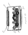
- FIG. 23 is an elevational view of an image-capturing device according to another embodiment of a system according to the invention.
- FIG. 24 is an elevational view of a portion of a lenticular sheet according to one embodiment of the invention.
- FIG. 25 is an elevational view of a portion of a lenticular sheet assembly according to one embodiment of the invention.
- FIG. 26 is a schematic illustration of a lenticular sheet assembly according to one embodiment of the invention illustrating how an image disposed on the sheet would appear to move when pressure is applied to the sheet in one of two directions.
- FIG. 27 is a schematic illustration of a lenticular sheet assembly according to one embodiment of the invention illustrating how an image disposed on the sheet would appear to move when pressure is applied to the sheet in one of two directions.
- FIG. 28 is a schematic illustration of a lenticular sheet assembly according to another embodiment of the invention illustrating how an image disposed on the sheet would appear to become enlarged when pressure is applied to the sheet in one of two directions.
- FIG. 29 a is a schematic illustration of a lenticular lens according to one embodiment of the invention illustrating the portion of an image that would be visible to a viewer prior to the application of pressure to the lenticular sheet.
- FIG. 29 b is a schematic view of a lenticular lens according to one embodiment of the invention illustrating the portion of an image that would be visible to a viewer during the application of pressure to the lenticular sheet.
- FIG. 30 is a perspective view of a lenticular lens according to another embodiment of the invention.
- FIG. 1 there is shown a presently preferred embodiment of a system 10 according to the invention.
- One or more images 12 comprising a set of images 14 are introduced to the system 10 for further processing, in order to make available certain interactive functions with respect to the set of images 14 .
- the number of images 12 in a set of images 14 depends, in part, on the level of sophistication of the interactive functions that are to be enabled for that set of images 14 .
- the set of images 14 may contain only a single image 12 .
- the user is to be able to interact with a set of images 14 in order to perceive the illusion of 3-D, then more than one image 12 will be necessary than if only a 2-D effect for the user is desired.
- the set of images 14 typically comprises sixteen images 12 of the object 16 , where each image 12 of a target object or scene is taken from a different angle, while desirably keeping the target object or scene at the same focal point for whatever device is used to capture the images 12 .
- a set of images 14 is shown that comprises sixteen images 12 of an object 16 , which happens to be a camera, that were captured by a digital camera.
- each image 12 shown was shot or taken from a different incremental angle about 360 degrees in certain plane of the object 16 , for example, every 22.5 degrees in the plane q of the object 16 , but the object 16 was kept at the same focal length from the digital camera that was used to take the pictures.
- the sixteen images 12 were viewed in sequence and in rapid succession, then the viewer would effectively perceive a 360-degree view in a particular plane q of the object 16 .
- the level of interactivity to be enabled is more sophisticated, such as allowing a user to virtually rotate an object in an image through a first 360 degrees in a first plane and a second 360 degrees in a second plane (i.e., to virtually spin an object in an image about two axes), then some multiple of sixteen images of the object 16 likely would be required, such as thirty-two images.
- a gyroscopic effect i.e., wherein an object appears to be capable of rotating in any plane, can be achieved if sufficient images in those planes are acquired.
- the numbers of images happen to be sixteen and a multiple of sixteen, virtually any odd or even number of images could be employed in keeping with the present invention.
- the images 12 are converted from the original form into digital form by any of several methods well known to those of ordinary skill in the art before being the images 12 are introduced to the system 10 . It is contemplated, however, that in other embodiments of the system 10 of the invention, the images 12 could be introduced to the system 10 in any non-digital form, without the need for conversion to digital form if the original form is not digital.
- an editing facility or feature 32 in which the images 12 in the sets of images 14 can be edited before being submitted for processing.
- a set of images 14 comprises a set of images of an object or scene taken from multiple angles
- the discrete images can be combined into a single image file, which subsequently can be edited with respect to such features as background color, contrast, brightness, grey scale, or any other number of editable aspects of a digital photograph, such as made available by several commercial editing programs.
- the images 12 are a set of images 14 that has been acquired by a digital camera then the set of images can be combined, either vertically or horizontally, to create a single image file.
- the packages sold under the trade name PHOTOSHOP by Adobe Systems, Inc. As will be obvious to one with ordinary skill in the art pertaining to this invention, other editing software programs exist or can be developed which allow various editing functions to be performed on combined sets of images.
- the images can be edited quickly and efficiently, because any changes made will be made to all of the images in the combined file (e.g., changing the background color will change the background color for all of the images comprising the input).
- the editing functions provided in the editing facility 32 can include functions that operate on single images, or less than all of the images in the set of images that comprise a set of images 14 .
- the set of images 14 is introduced into the system 10 where the set of images 14 is processed by software 20 that is implemented on a suitable computer or processor.
- other information relating to the set of images 14 also can be introduced into the system 10 , such as information concerning the actual physical dimensions of an object 16 depicted in a set of images 14 (e.g., the height, width, and/or depth of the object in inches, feet, etc.), and information that controls certain aspects of the interactive functions that are enabled for the set of images 14 (e.g., a zoom factor that determines the maximum degree to which an image can be zoomed in on).
- the software 20 may calculate the actual physical dimensions of an object 16 depicted in a set of images 14 , based on information concerning the actual physical dimensions of the location at which the images 12 were captured, together with information concerning the focal length, l, of the camera with respect to the object 16 , etc.
- the software 20 may apply default values if information that optionally can be introduced is not, in fact, introduced, such as a default value for the zoom factor.
- the software 20 both controls the manner in which the set of images 14 is delivered to a user in response to the user's request 60 and, once the set of images 14 is delivered, permits the user to initiate and carry out a variety of interactive functions with respect to the set of images 14 .
- these interactive functions may include providing the user with the illusion of moving an object 16 in two dimensions (e.g., vertically or horizontally), zooming in on an object 16 , or rotating an object 16 to obtain a 3-D effect.
- the software 20 advantageously can be added to the HTML or XML code 23 that already exists on a third party provider's web pages (either as developed by the web site provider or as contained in a banner advertiser's content for the web site provider), so as to provide the third party website provider or banner advertiser with the ability to offer users (1) the perception of fast image download or delivery time; and (2) 2-D or virtual 3-D viewing without the necessity of the user either already having or having to download plug-ins to enable the interactivity; and (3) enhanced image quality when a zoom in function is carried out.
- a third party provider's web pages either as developed by the web site provider or as contained in a banner advertiser's content for the web site provider
- the software 20 is written in the language corresponding to the software protocol known as DHTML or “Dynamic Hypertext Markup Language,” and advantageously uses the layering feature available in the protocol.
- the system 10 could be implemented by using any other protocol or language, suitable for web-based use or non-web use, that permits apportionment of sets of images for fast delivery to a user with which the user can initiate interactive functions such as those described herein.
- the software 20 is written in a language that is specifically used in connection with web pages that are intended to be viewed using a browser, i.e., a “client” software program that allows a user to view web pages and which usually is used to search for and view web pages from a website accessible over the Internet.
- a browser can also be used to view web pages that are stored on a suitable device such as a CD-ROM or a local computer hard drive, without the need for an Internet connection.
- a suitable device such as a CD-ROM or a local computer hard drive
- the basic functionality of the software 20 e.g., the results achieved by apportioning each of multiple images of an object into discrete layers and making only one of the multiple images viewable to the user at a given time, can also be implemented in other languages, such as C, where the intended use of the system 10 is a use not related to the Internet.
- the functionality of the software 20 can be described as follows: When the system 10 according to the invention detects a request 60 for a certain set of images 14 that are present on a third party website, the requested set of images 14 is delivered to the user by taking advantage of the layering features that are available in the DHTML software protocol. Specifically, by example and with reference to FIGS. 4-5 , if the user sends a request related to an object 16 that is viewable to the user on a third party provider's website, the system 10 according to the invention will couple or add the software 20 with the code on the web page that the third party website provider otherwise would deliver to the user in response to his or her request.
- the software 20 will instantaneously create a DHTML layer 200 for each file that corresponds to the set of images 14 that are requested. If the set of images 14 associated with the object comprises sixteen images 12 , then sixteen layers 200 a - 200 p will be created. Each of the image layers 200 is originally sized to have approximately the same dimensions in terms of height and width (although the dimensions of each image layer 200 a - 200 p can change when certain interactive functions, such as the zoom function, are performed).
- the first layer 200 a created for a predetermined one of the images 12 (i.e., whichever image 12 the user is intended to see first) will be immediately perceptible or viewable by the user upon delivery in a viewable area defined by a border on the user's display.
- the user upon the website's processing of the user's request 60 for the pertinent web page, the user will immediately perceive one of the multiple images associated with the request. From the perspective of the user, therefore, there is virtually no delay between the time the request for the web page is processed and the time the first image is viewable.
- the other fifteen layers 200 b - 200 p are being created after it, but are not yet made visible to the viewer.
- only one image layer 200 is made perceptible or visible to a user at any given time. Whichever image layer is perceptible or visible is the currently viewable image layer.
- the user will perceive an image corresponding to his or her request almost immediately, and will not have to wait for all of the images 12 in the set of images 14 to be delivered to his or her computer's cache memory or hard drive.
- the user can view the set of images 14 without any delay as typically would be incurred when images are delivered using JAVA (an object-oriented programming language developed by Sun Microsystems, Inc.), and without the necessity of any additional software, such as that provided in a plug-in.
- JAVA an object-oriented programming language developed by Sun Microsystems, Inc.
- the software 20 of the system 10 might be provided to enable delivery of sets of images 14 and interactivity with sets of images other than via a web page, such as in an application program that is made available to users separately from the sets of images 14 and web pages, for example, by being downloaded from a website or provided on a CD-ROM.
- the system 10 according to the invention can be used advantageously to deliver sets of images 14 that are part of the primary content of a website, or alternatively, in connection with banner advertisements.
- the sets of images 14 could be delivered as part of a banner advertisement that a third party advertiser has arranged with the website provider to deliver on certain web pages that are requested by a user.
- connection when the connection is a relatively slow connection, such as a dial-up modem connection, one embodiment of the system 10 according to the invention further apportions each of the images 12 in the set of images 14 for delivery into a grid of multiple parts or “splits” 22 for delivery.
- An example of an image 12 that has been “split” into sixteen parts is illustrated schematically in FIG. 6 . If the dial-up connection is corrupted or lost in the middle of delivery of a web page, the splits 22 that made it to the user's cache memory or hard drive before the connection was lost do not have to be re-sent when the connection is reestablished.
- the number of splits 22 that each image file is apportioned into for delivery is sixteen or thirty-two, but any odd or even number of splits can be accomplished.
- a tool bar layer 202 is created that contains a tool bar 100 which is also made viewable to the user along with the predetermined one of the image layers 200 a at the time of initial delivery of the set of images 14 .
- the tool bar layer 202 has at least one dimension that is generally less than the corresponding dimension of the image layers 200 , for example, the tool bar layer 202 might have approximately the same width as the image layers 200 but a height that is substantially less than the height of the image layers 200 , so that whichever image layer 200 is currently viewable to the user can be clearly seen despite the presence of the tool bar 100 .
- a first transparent layer 204 is provided underneath or behind the tool bar layer 202 , and on top of or in front of the image layers 200 .
- the first transparent layer 204 is sized to have dimensions that approximate the dimensions of the image layers 200 , both in terms of height and width. Whenever the currently viewable image layer 200 is caused to change in size, e.g., during a zoom interactive function, the first transparent layer 204 adjusts in size to match that of the currently viewable image layer 200 .
- the first transparent layer 204 is especially useful in carrying out certain of the interactive functions with respect to the set of images 14 , i.e., the manual rotate function and the measuring function as described hereinbelow.
- the transparent layer 204 also allows other of the interactive functions to be carried out efficiently, such as the pan or move function, because movement of the first transparent layer 204 causes all of the image layers 200 to move along with it. (Under some circumstances, the first transparent layer 204 may afford the additional advantage of limiting the degree to which a user may copy the currently viewable image in the image layers 200 , as the copy function may result in the copying of no more than the first transparent layer 204 and/or the first transparent layer 204 and the tool bar layer 202 .)
- the first transparent layer 206 is provided a second transparent layer, which primarily is used in connection with the measuring function described hereinbelow.
- buttons or icons on the tool bar 100 are provided, some of which merely enable certain interactive functions and others of which both enable interactive functions and control, to some degree, how the interactive functions are carried out with respect to the set of images 14 .
- commands can be conveyed to a system by a variety of means, such as via a mouse or a similar device such as a touch screen (e.g., sending commands by moving a finger from point to point on a touch screen display).
- Commands can be associated with various positions or states of a mouse with respect to a display.
- commands can be associated with the positions or states of “mouse over” and “mouse click,” and, in some systems such as the preferred embodiments of the system according to the present invention, with the positions or states of “mouse up,” “mouse down,” and “mouse out.”
- the software 20 can be configured such that each one of these commands initiates some corresponding action with respect to the buttons in the tool bar 100 .
- buttons on the tool bar 100 illustrated in FIG. 7 correspond to the following interactive functions: (1) the button 102 , which can be in the form of a logo (as shown in FIG.
- the button 104 which is comprised of a thumb or knob 106 and a horizontally disposed track 108 , enables the user to zoom in on or zoom out of an image 12 ;
- the “reset” button 110 which enables the user to return to the whatever first predetermined or selected image layer 200 was originally delivered to the user and in the form in which it was originally delivered (e.g., not zoomed in on);
- the “measure” button 112 enables the user to use a mouse or similar device to first identify a certain dimension of an object in an image and then to obtain information concerning an actual physical dimension corresponding to that certain dimension;
- the “pan or move” button 114 which
- buttons on the tool bar correspond, in a preferred embodiment of the system 10 according to the invention, whenever the user clicks on a button or icon on the tool bar 100 , a description of how the user can interact with the requested set of images 14 using that button—i.e., the icon's functionality—appears or “pops up” on the display, as is shown in the text boxes of FIG. 7 .
- the user when a user first begins use of the system according to the invention, the user might be presented with a look-up table, help menu or other information which describes each of the buttons on the tool bar, so that no prompting of the user is necessary when the “manual rotate” button (or any other button) is activated.
- a look-up table which describes each of the buttons on the tool bar
- help menu or other information which describes each of the buttons on the tool bar
- the tool bar layer 202 as well as all of the image layers 200 except the currently viewable image layer 200 might be kept hidden from view upon delivery of a set of images 14 .
- another different layer might be made visible together with the currently viewable layer 200 that contains an icon or other symbol that can invoke the tool bar layer 202 . That is, when a user moves his or her mouse over the symbol or icon in this tool-bar-invoking layer, the user's action causes the system 10 to make visible the tool bar layer 202 along with the currently viewable layer 200 .
- the tool-bar-invoking layer will be hidden when the tool bar layer 202 and the currently viewable image layer 200 are made visible.
- the tool-bar-invoking layer is sized so as to be smaller than the image layers 200 , for example, one tenth of the height and width of the image layers 200 , so that the tool-bar-invoking layer, when visible to the user, would not interfere to any significant degree with the user's perception of the currently viewable image layer 200 .
- a feature might be provided in the system 10 according to the invention where the tool bar 100 in the tool bar layer 202 has a button or icon which, when activated by the user by some action such as a mouse over or the like, will cause the tool bar layer 202 to become hidden from the user's field of view and replaced by the tool-bar-invoking layer, such that the user will again perceive only the tool-bar-invoking layer and the currently viewable image layer 200 in his or her field of view at one time.
- the “reset” button on the tool bar is used to hide the tool bar from view, such that only the currently viewable layer 200 and the icon in the tool-bar-invoking layer are perceptible by the user.
- Features such as described above allow users who are familiar with the various interactive functions of the system 10 to hide the tool bar 100 altogether when desired, in order to eliminate the tool bar 100 as a possible distraction on the users' display while the users are perceiving the currently viewable image layer 200 .
- Some of the interactive functions that are available as options on the tool bar 100 are entirely carried out when the pertinent button or icon on the tool bar is activated, for example, when the user clicks on the button and holds the mouse button down on the autorotate left or autorotate right buttons, the system 10 will cause the currently viewable image layer to cycle through image layer 200 a through 200 p or through image layer 200 a and then through image layers 200 p , 200 o , etc., respectively.
- moving the mouse over, pressing down on the mouse button, or clicking on the button causes the system 10 to be placed in that particular interactive function mode, and the user has to move the mouse with respect to the currently viewable image layer 200 in order to carry out the interactive function, whereby the function performed responds to commands from the mouse corresponding to the coordinates of the mouse on the first transparent layer 204 or on the currently viewable image layer 200 .
- the system 10 has a feature whereby the user can change the orientation of the tool bar 100 on the user's display. That is, by pressing down a mouse button and/or clicking on a mouse while the mouse is positioned anywhere within the tool bar layer 202 , the user can cause the tool bar 100 to be moved anywhere on the user's display, either to a position somewhere within the viewable area in which the currently viewable image layer 200 is being displayed, or completely outside of that viewable area (e.g., beyond the border of that viewable area) so that the tool bar 100 does not interfere with user's ability to perceive the entirety of the currently viewable image layer 200 .
- the tool bar 100 will be moved from x 1 , y 1 to x 2 , y 2 .
- the tool bar 100 will be moved on the display, for example, outside of the field of view of the currently viewable image layer 200 altogether.
- a button or icon on the tool bar layer might provide a visual cue to a user for the move toolbar function, such as, the button 102 , which in the figure happens to be the logo of the provider of the system 10 .
- the zoom interactive function of the system 10 according to the invention in particular, reflects several significant advantages over zoom interactive functions of prior art systems. More particularly, the zoom interactive function of the system 10 according to the invention allows a user to perceive a smoothly executed zoom, wherein the size of the viewable area within which the zoom is being performed increases to accommodate the enlarged image, and the dimensions of the currently viewable image layer 200 that is being zoomed in on are adjusted proportionally as the zoom is carried out. Moreover, the resolution of the image 12 in the currently viewable image layer 200 after the zoom remains high, because high resolution images can be delivered to a user with the system 10 according to the invention without any appreciable delay caused by the large amount of data that is associated with the high resolution images.
- the system 10 enables and performs the zoom interactive function according to the following:
- a predetermined zoom factor, z, for a given set of images is associated with the set of images 14 by the software 20 .
- the zoom factor comprises a limit on the degree to which a particular set of images 14 can be zoomed in on or, alternatively, on how big the object in the set of images 14 can get.
- the particular value of the zoom factor, z is selected so as to optimize the appearance of an object in a set of images 14 when it is zoomed in on, with regard to such factors as how smoothly the zoom function will appear to be carried out (if the image gets too large too quickly, the appearance of the zoom may not be smooth), and how to fix the maximum zoom in to a level that will not distort the images.
- the zoom factor, z might be introduced at the time the set of images 14 is introduced to the system 10 , or at some later point (e.g., if the set of images 14 is being managed by the webmaster of a third party provider's web site, the webmaster may be able to adjust the zoom factor, z, at any time.)
- the software 20 may contain a default value for the zoom factor, z, in the event no value for that parameter is otherwise specified by the user (or webmaster).
- the zoom interactive function of the system 10 advantageously allows a high resolution image to be perceived by a user upon zooming in on the image.
- the set of images 14 consists of only one image 12 , for example, in the case where only interactive functions in two dimensions are to be enabled and only with respect to a single image of an object, the image 12 can be delivered rapidly to a user regardless of how high the image resolution is, because no delays will be incurred as might be incurred if the images were delivered using a language such as JAVA (which is typically associated with long delivery times) or additional software such as provided in a plug in.
- JAVA which is typically associated with long delivery times
- the quality of the zoom interactive function is not at all compromised by the number of images 12 that compromise the set of images 14 .
- the images 12 in the set of images 14 do not have to be assembled into a single large image file as a precondition to making the images available to the user. Rather, each image 12 in the set of images 14 is provided in its own image layer 200 by the software 20 , the resolution of the images being delivered does not have to be sacrificed in order to keep the delivery time to a minimum.
- the user since the user perceives the image 12 provided in the predetermined or selected first image layer 200 at the instant of delivery, the user will perceive no delay in delivery time when multiple images, each with relatively high resolution, e.g., 1024 ⁇ 768 pixels, are being delivered. If the maximum available resolution is 1024 ⁇ 768 for any given one of the images 12 in a set of images 14 , the original images made viewable to the user (i.e., the non-zoomed-in-on images), can be presented at a resolution of, for example, 320 ⁇ 240 pixels.
- the software 20 When a zoom-in interactive function is commanded, and according to the zoom factor, z, the software 20 will reveal more of the available pixels to the viewer as the image is zoomed in on, up to a maximum of 1024 ⁇ 768 pixels in this example. Accordingly, the quality of an image 12 is not compromised at all when a zoom-in interactive function is carried out.
- the zoom factor, z is an arbitrary number, such as five.
- the zoom interactive function of the system 10 according to the invention not only expands the entire currently viewable image layer 200 , but also expands the viewable area within which the currently viewable image layer is displayed to the user.
- the user can continue to view the entirety of an object depicted in an image 12 as the currently viewable image layer 200 is enlarged.
- an associated algorithm adjusts the direction in which the size increase occurs, so as to give the user the illusion that when an object in an image is zoomed in on, it increases in size in all directions equally or proportionately. That is, without such an adjustment, when a zoom in operation is carried out with respect to an image, the image will appear to move down and to the right on the display as it increases in size (i.e., as the height of the image increases the image will increase in size downwardly, and as the width of the image increases the image will move increase in size to the right).
- the image With the adjustment of the system 10 according to the invention, as the height of the image increases in size downwardly, the image is immediately shifted back in the opposite direction by half of the increase in height and, similarly, as the width of the image increases in size to the right, the image is immediately shifted back in the opposite direction by half of the increase in width. In this manner, the image appears to increase in size equally in both the directions of height and width.
- the reset interactive function is carried out entirely when the reset button 110 on the tool bar 100 is clicked on with a mouse or otherwise activated.
- the reset function causes all of the layers (the image layers 200 , the tool bar layer 202 , the transparent layers 204 , 206 and any tool-bar-invoking layer) to be restored to their original positions, i.e., the positions that all of the layers were in at the time the set of images 14 was first delivered to the user.
- the display is illustrated after a tool bar move function has been carried out, such that the tool bar layer 202 is located outside of the field of view of the first transparent layer 204 and the currently viewable image layer 200 .
- the measuring interactive function wherein the second transparent layer 206 has special significance in a presently preferred embodiment of the system 10 according to the invention, will now be described with reference to FIGS. 14 and 15 .
- the system 10 will be put into measuring mode when the user presses down on the mouse button and/or clicks on the button 112 on the tool bar 100 that corresponds to the measuring interactive function.
- the user clicks and drags the mouse over one of the dimensions, e.g., height or width, of an object depicted in the currently viewable image layer 200 the first transparent layer 204 will move over the second transparent layer 206 , which remains fixed.
- a line, m will be drawn on the second transparent layer 206 which corresponds to the distance the first transparent layer 204 has moved relative to the second transparent layer 206 , i.e., a line corresponding to the coordinates of the mouse position before and after the mouse is dragged, e.g., the starting point when the mouse began to be dragged, x 1 , y 1 , and the ending point when the dragging of the mouse is stopped, e.g., x 2 , x 2 .
- the actual physical value corresponding to the dimension the user measures with the measuring tool can be calculated based on the number of pixels comprising the line m and information about the actual physical dimensions of the object 16 that is known by the system 10 .
- Information about the physical dimensions of the object 16 may be known by the system 10 by reason of the fact such information was input to the system 10 at some point prior to use of the measuring tool, e.g., at the time the set of images 14 was introduced to the system 10 .
- information about the physical dimensions of the object 16 may be known by the system 10 by reason of the fact that information about the dimensions of the space surrounding the object 16 in the images 12 are known to the system 10 .
- the images 12 are acquired using one of the image-capturing devices 600 described hereinbelow, sufficient information about the actual physical dimensions of the space defined by the interior of the image-capturing device 600 can be introduced to the system 10 from which the actual physical dimensions of an object 16 that is introduced into that space can be calculated by the system software 20 .
- this function is carried out, once enabled, according to the difference between a first position of a user's mouse (or similar device providing x and y coordinate information) and a second position of a user's mouse as the mouse is dragged from the first position to the second position.
- the transparent layer 204 together with all of the image layers 200 and, optionally, the tool bar layer 202 , will move from the first position to the second position along the line defined by the distance from x 1 , y 1 to x 2 , y 2 .
- the transparent layer 204 and the image layers 200 will move diagonally.
- the layers will move horizontally, if the line corresponds to a vertical line across the display, then the layers will move vertically, etc.
- a user can cause an object depicted in a set of images 14 to appear to rotate enabling one of two “autorotate” functions and/or a “manual rotate” function.
- a user may enable an autorotate function in one of two directions, i.e., right or left, by clicking on the appropriate button or icon 116 , 120 .
- the autorotate mode whichever image layers 200 in the set of images 14 that corresponds to a 360-degree view of an object in a particular plane, q, will be successively, and for a selected increment of time, be made the currently viewable layer.
- the object 16 of interest is a camera
- the “rotate left” autorotate function is enabled by clicking on the appropriate tool bar button or icon 120
- the currently viewable image layer e.g., the first image layer 200 a
- the next sequential image layer e.g., second image layer 200 b
- the image layers are cycled through in this fashion, with each respective image layer 200 a - 200 p being made visible to, and subsequently hidden from, the user, at a predetermined or selected increment of time.
- the image layers 200 will continue to be displayed to the user sequentially, with one of the image layers 200 a - 200 p after another being made the currently viewable image layer and then hidden, until the user disengages the autorotate interactive function (e.g., by letting up on the mouse button over the autorotate button on the tool bar).
- the autorotate interactive function e.g., by letting up on the mouse button over the autorotate button on the tool bar.
- the currently viewable image layer 200 will remain as that middle image layer 200 g when the autorotate function is disengaged.
- the image layers 200 might be cycled through in the opposite direction, e.g., from the first image layer 200 a , to the last image layer 200 p , to the next to last image layer 200 o , etc.
- a user may be able to command rotation of an object 16 depicted in a set of images 14 about 360 degrees in more than one plane, depending on the nature and type of the images 12 that have been acquired for the object 16 .
- the user could achieve the effect of rotating in a vertical direction (e.g., “rotate top” or “rotate bottom”) in addition to the horizontal directions (i.e., “rotate left” or “rotate right”).
- a vertical direction e.g., “rotate top” or “rotate bottom”
- the horizontal directions i.e., “rotate left” or “rotate right”.
- the “manual rotate” is an alternative to the “autorotate” function for the user to perceive a virtual 3-D effect of an object. Rather than initiating the illusion of rotation by clicking on, or holding the mouse button down on top of, one of the “autorotate” icons on the tool bar, the “manual rotate” function is carried out by a user by first clicking on the “manual rotate” icon 118 on the tool bar 100 , and then moving the mouse to a point somewhere in the currently viewable image layer. The user next presses down on the mouse button and drags the mouse in the direction the rotational effect is desired.
- the degree of rotation i.e., the number of image layers 200 in the set of image layers 200 a - 200 p that sequentially will be made the currently viewable image layer and then hidden, will depend in part on how far the user drags the mouse across the image.
- the speed at which the relevant ones of the image layers 200 a - 200 p are made currently viewable to, and then hidden from the user, will depend in part on how fast the user drags the mouse across the image.
- the user has a greater degree of control over how the rotation interactive function is executed by the system 10 than when the autorotate interactive function is performed.
- the manual rotate function could be used to provide a gyroscopic virtual 3-D effect with respect to the object, by causing the object 16 to appear to rotate in multiple planes of the object when the mouse is dragged on the currently viewable image layer 200 in different directions, where each direction corresponds to a different plane of rotation.
- the interactive functions desirably include one or more of the following interactive functions: (1) panning or moving an image layer from place to place on a display; (2) measuring one or more physical dimensions of an object depicted in the currently viewable image layer; (3) zooming into or zooming out on the currently viewable image layer; and (4) a resetting function which resets the tool bar layer, the transparent layer(s) and the image layers to the form in which the appeared at the time the set of images 14 was delivered to the user.
- only one image layer 200 might be created for a given set of images 14 , whereby the currently viewable image layer 200 , e.g., the predetermined or selected one of the images 12 made viewable upon delivery of the web page to the user, or whichever one of the images 12 is made viewable during the performance of an interactive function, is swapped in and out of a single image layer 200 .
- the tool bar layer 202 and/or the transparent layers 204 , 206 might be optional.
- a user may acquire one or more images of an object on their own, such as by taking multiple digital photographs of an object from different angles in a particular 360-degree plane.
- the user then might upload the acquired images to the website of a provider of the system 10 according to the invention, whereupon the system provider would associate the software 20 with the user's set of images to enable various possible interactive functions, perhaps as selected by the user from among a menu of available interactive functions.
- the system provider would then deliver the interactivity-enabled set of images back to the user via any suitable means, such as via web pages or on a CD-ROM or other storage device.
- the user could then use his or her own processor to implement the software 20 and carry out the available interactive functions, for example, in the course of a presentation using the POWERPOINT program available from Microsoft Corporation.
- a user may be able to obtain the software 20 and associate his or her images with the software 20 directly, using the processor of his or her computer to implement the software 20 , so as to enable the images for interactivity.
- the software 20 might include prompts for the user to enter certain parameters to tailor the available interactive functions for different sets of images.
- the software might include prompts for information that are simpler to follow, such as “upload image # 1 ,”“upload image # 2 ,”“enter the height of the object in inches,” etc.
- the software 20 can be associated with a set of images 14 that are intended to be delivered to, and interacted with by, users who request the sets of images 14 over an intranet, or who download the sets of images 14 and the software 20 to temporary or permanent memory on their personal computers, PDAs (“Personal Data Assistants”), cell phones or other devices suitably equipped to accept the delivered sets of images 14 and to implement the software 20 with an appropriate processor.
- PDAs Personal Data Assistants
- cell phones or other devices suitably equipped to accept the delivered sets of images 14 and to implement the software 20 with an appropriate processor.
- the same basic principles for the delivery of images and the enabling of interactive functions with respect to those images can be applied, with or without the use of the software 20 , to render images on various forms of printed media, such as lenticular sheets, sets of images 14 with which a user can interact so as to perceive the illusion of 2-D or 3-D motion, as is described in more detail hereinbelow.
- systems including apparatuses and methods, which allow users to control the creation of images of objects of their own choosing which can be processed and displayed by the processing and display system and method described hereinabove.
- individual, corporate, or government users may be provided with means for acquiring a digital image of a desired object, the digital image being comprised of multiple image files or a single image file, which can then be processed and displayed to a user in a 2-D or 3-D form with which the user can interact in some fashion.
- the means for acquiring the digital image desirably comprises scalable, stand-alone machines and devices for the creation of both 2-D and 3-D images of objects (including but not limited to inanimate objects, people and animals).
- the object for which a digital image is to be acquired would be placed or driven into (e.g., as a car or a truck) inside one of these image-capturing machines or devices.
- the size of the image-capturing device might range from inches-cubed to hundreds of feet-cubed. The maximum and minimum sizes for the image-capturing devices are limited only by the limits of current technology.
- the image-capturing device 600 has an approximately cylindrical barrel 602 , having a top surface 604 and a bottom surface 606 .
- a lid 607 is provided, with or without a hinge, in order to allow an object 16 to be imaged to be introduced to the interior of the enclosure formed by the cylindrical barrel and the top surface and the bottom surface.
- the image-capturing device 600 is configured to allow a plurality of images to be captured of the object 16 .
- the object 16 remains stationary while the image-capturing process occurs.
- a plurality of cameras or lenses 610 are disposed at regular intervals in the interior of the enclosure, preferably about a circumference of the cylindrical barrel 602 .
- a platform 608 optionally is provided in the interior above or on top of the bottom surface 606 on which the object 16 to be imaged can be oriented.
- the platform 608 can be provided with markings, such as grid marks, to assist in orienting the object 16 such that it is placed at the appropriate focal length for the plurality of cameras or lenses 610 .
- Multiple lenses 610 can be connected to a single camera or other imager or device for acquiring images.
- a user can specify the number of images to be captured of the object 16 by interfacing with the image-capturing device 600 via an appropriate control device, such as a touch screen or keypad 612 that is associated with a processor that sends commands to and, optionally, receives data from, the image-capturing device 600 .
- a display also can be provided exterior to the image-capturing device 600 , such as on the outer surface of the cylindrical barrel 602 or on an adjacent stand or table, which is in communication with the interior of the image-capturing device 600 .
- a user therefore might observe the object while the images are being captured, or be able to view each image after it is captured, for example, to determine whether the quality of the image is satisfactory or whether the image should be re-taken.
- the touch screen or keypad 612 or other comparable device might be provided to enable the user to preview different possible angles at which images of the object might be captured.
- the processor will command the appropriate camera or lens 610 to acquire the image from the desired angle.
- the processor can also be used to configure the captured images in a form that can be output to the user, e.g., on a disk, a CD-ROM, or via a physical or wireless connection to a user's computer or other device capable of receiving the captured images.
- the processor can also be used to configure the captured images in a form that can be output to the user on some form of printed medium, such as a lenticular sheet or lenticular sheet assembly as is described hereinbelow.
- the processor further can be configured to associate the captured images directly with the software 20 that later can be implemented by a user's computer or other processor, or other device capable of rendering the images in printed form, such as a printer.
- the image-capturing device 600 is provided with one or more features that are intended to minimize the degree to which the captured images requiring editing as a prerequisite to carrying out interactive functions (e.g., a virtual 3-D effect) with respect to the images.
- appropriate lighting is built in to the image-capturing device 600 , so that the interior can be optimally illuminated for image capture.
- lighting can be introduced into the interior from an external source through the opening defined by the lid, through some other opening created for the purpose of introducing light or the like. Lighting of different quality can be offered as an option to a user, for example, when the use of higher quality lighting would make the process of image capture more expensive to a user than when less quality lighting is used.
- the mechanical aspects of the cameras or lenses 610 and/or lighting can be hidden or partially hidden with respect to the interior of the image-capturing device 600 by covering the lenses and/or lighting with an opaque material or can otherwise be made opaque, so the mechanical parts of the cameras or lenses 610 will not be seen in the captured images.
- the interior of the image-capturing device 600 also can be made uniform in color, such as white, so as to optimize isolation of the object 16 for image capture.
- the bottom surface 606 or platform 608 on which the object 16 is positioned for image capture can be made transparent, to prevent the surface or platform from interfering with image capture and, optionally, to allow images to be taken of the object from below the object.
- an image-capturing device 600 of the system 10 In a presently preferred embodiment of an image-capturing device 600 of the system 10 according to the invention, all of the images to be captured of an object 16 are captured simultaneously, with one image being captured by each of the plurality of lens 610 .
- the time associated with the process of capturing a plurality of images of an object at different angles, but at approximately the same focal length, is optimized.
- each image of the object 16 might be captured sequentially by the lenses 610 , but with an imperceptible delay between the time each image of the object is acquired.
- an image-capturing device 600 may be equipped with sixteen cameras or lenses 610 , where sixteen images is a satisfactory number of images to take of an object when a virtual 3-D effect, e.g., providing the illusion of rotation of the object, is desired. Only one image might be optimal if only 2-D interaction is to be enabled.
- the number of images to be captured of an object 16 placed in the interior of the image-capturing device 600 can be determined by the user and communicated to the image-capturing device 600 via the touch screen 612 , however, other suitable means of communicating this information will be apparent to one of skill in the art.
- a user may be able to provide the image-capturing device 600 with other information concerning the object for which images are captured.
- the user may provide dimensional information, e.g., the height, width and depth of an object in inches or centimeters.
- An algorithm in the software 20 later during an interactive measuring function by using a ratio of the actual physical dimensions to the corresponding dimensions measured in pixels in the image.
- information concerning the physical dimensions of the interior of the image-capturing device 600 and the positioning of the lenses 610 , etc. can be used by the software 20 to calculate a given physical dimension of an object based upon the number of pixels the dimension comprises in an image.
- means can be provided for moving the object 16 relative to one or more cameras or lenses 610 , such as a turntable disposed in the interior of the image-capturing device.
- means could be provided for moving one or more cameras or lenses 610 disposed in the enclosure defined by the image-capturing device 600 relative to an object 16 that is kept stationary.
- FIGS. 18-23 Other embodiments of an image-capturing device 600 of the system 10 according to the invention will now be described with reference to FIGS. 18-23 .
- the image-capturing device 600 would be sized to enable a set of images to be taken of a person's head or head and shoulders, for example, for use with some form of security or identification system.
- the image-capturing device 600 again has an approximately cylindrically-shaped barrel 620 , but the top 621 and bottom 622 of the cylindrically-shaped barrel 620 are left apertured and uncovered.
- the image-capturing device 600 of FIG. 18 is configured to allow a plurality of images to be captured of the object 16 that is placed inside the cylindrically-shaped barrel 620 , which in this case is intended to be a person.
- the person will be instructed to remain stationary while the image-capturing process occurs.
- a plurality of cameras or lenses 624 are disposed at regular intervals about a circumference of the cylindrical barrel 620 .
- a platform might be provided at the subject's feet in order to guide the person where to stand so as to keep his or her head and shoulders at the appropriate focal length with respect to the lenses 624 .
- the cylindrically-shaped barrel 620 is provided on an adjustable pole 626 , oriented roughly perpendicular to the cylindrically-shaped barrel 620 , so that the cylindrically-shaped barrel 620 can be moved or moved up and down the pole to accommodate subjects of different heights, and subjects can orient properly orient themselves with respect to the cylindrically-shaped barrel 620 without having to bend or stoop.
- the image-capturing device 600 shown in FIG. 18 is also provided with one or more features that are intended to minimize the degree to which the captured images requiring editing as a prerequisite to carrying out interactive functions (e.g., a virtual 3-D effect) with respect to the images.
- appropriate lighting can be built in to the image-capturing device 600 , so that the interior can be optimally illuminated for image capture.
- appropriate lighting would be lighting that is suitable for the overall size of the image-capturing device and the scale of the objects to be imaged (e.g., different lighting requirements would be appropriate for large objects such as vehicles, boats or aircraft than would be appropriate for items of a microscopic scale).
- lighting can be introduced from an external source, such as lighting directed through the top opening 621 and/or the bottom opening 622 .
- Lighting of different quality can be offered as an option to a user, for example, when the use of higher quality lighting would make the process of image capture more expensive to a user than when less quality lighting is used.
- the mechanical aspects of the cameras or lenses 624 and/or lighting can be hidden or partially hidden with respect to the interior of the image-capturing device 600 by covering the lenses and/or lighting with an opaque material or can otherwise be made opaque, so the mechanical parts of the cameras or lenses 624 will not be seen in the captured images.
- the interior of the image-capturing device 600 also can be made uniform in color, such as white, so as to optimize isolation of the object 16 for image capture.
- the image-capturing device 600 illustrated in FIG. 18 optionally can be provided with means for controlling certain aspects of the image-capturing process, such as the number of images to be captured.
- a touch screen or key pad or other suitable device for delivering commands to the image-capturing device either can be provided on a surface of the image-capturing device 600 or can be otherwise coupled to it.
- fewer images of an object 16 may be captured than there are cameras or lenses 624 in the image-capturing device 600 .
- an image-capturing device 600 may be equipped with sixteen cameras or lenses 624 , where sixteen images is a satisfactory number of images to take of an object when a virtual 3-D effect, e.g., providing the illusion of rotation of the object, is desired. Only one image might be optimal if only 2-D interaction is to be enabled.
- the image-capturing device 600 of FIG. 18 can further be provided with a top cover 630 disposed over and covering top opening 621 .
- the top cover 630 may be curved, with a semicircular cross section.
- the cover can be provided with one or more additional cameras or lenses 624 to enable images to be captured from still other angles of a person's head and shoulders, such as angles that will capture the top of a person's head.
- the cover also will help minimize the editing required of the captured images later on, by helping to isolate the person's head and shoulders during image capture.
- the interior surface 632 of the top cover 630 preferably is uniform in color, such as all white, or all off-white, in order to further enhance image capture.
- an image-capturing device 600 similar in appearance to the image-capturing device 600 shown in FIG. 18 could be configured so that the cylindrically-shaped barrel 620 moves relative to the subject, whereby one or more cameras or lenses disposed in the interior of the cylindrically-shaped barrel 620 moves relative to the subject, who would remain stationary, during the image-capturing process.
- a person-sized image-capturing device also could be provided in which the cylindrically-shaped barrel containing one or more cameras or lenses remains stationary while the subject rotates before the camera(s) or len(ses) on a rotatable platform or stool.
- An image-capturing device 600 is shown in FIG. 20 that can accommodate an entire person's body, or any similarly-sized animal or object. Multiple cameras or lenses 630 are disposed about an inner circumference, c, of the image-capturing device 600 so as to capture images of whatever object is placed in the image-capturing device 600 from a variety of different angles.
- a door 634 can be provided to allow ingress and egress from the interior of the image-capturing device 600 in order to place objects inside and then remove the objects after the image capture process has been completed.
- an image-capturing device 600 of the system 10 according to the invention can be designed to have virtually any shape other than cylindrical, although cylindrical or spherical shapes are presently preferred when the images to be captured are to be used in connection with a virtual 3-D type of interactive effect.
- the image-capturing device 600 illustrated in FIGS. 21-22 is generally spherical in shape, with a non-spherical base 639 to keep the image-capturing device 600 stable with respect to the surface on which it is used.
- the image-capturing device 600 is provided with multiple cameras or lenses 640 disposed about more than one inner circumference of the image-capturing device 600 , such a first inner circumference, c 1 , and a second inner circumference, c 2 .
- a transparent platform 642 might be provided on which to place an object 16 and to allow images to be captured from above and below the object 16 .
- the transparent platform 642 might be capable of rotation about a central axis thereof.
- Lighting 644 may be provided in the interior of the image-capturing device 600 to facilitate image capture and to enhance the quality of the images obtained.
- a user can specify the number of images to be captured of the object 16 by interfacing with the image-capturing device 600 via an appropriate control device, such as a touch screen or keypad 646 .
- a display also can be provided exterior to the image-capturing device 600 , such as on an adjacent stand or table, which is in communication with the interior of the image-capturing device 600 .
- a user therefore might observe the object while the images are being captured, or be able to view each image after it is captured, for example, to determine whether the quality of the image is satisfactory or whether the image should be re-taken.
- the image-capturing device 600 is provided with one or more features that are intended to minimize the degree to which the captured images requiring editing as a prerequisite to carrying out interactive functions (e.g., a virtual 3-D effect) with respect to the images.
- appropriate lighting is built in to the image-capturing device 600 , so that the interior can be optimally illuminated for image capture.
- lighting can be introduced into the interior from an external source through an opening created for the purpose of introducing light or the like. Lighting of different quality can be offered as an option to a user, for example, when the use of higher quality lighting would make the process of image capture more expensive to a user than when less quality lighting is used.
- the mechanical aspects of the cameras or lenses 640 and/or lighting can be hidden or partially hidden with respect to the interior of the image-capturing device 600 by covering the lenses and/or lighting with an opaque material or can otherwise be made opaque, so the mechanical parts of the cameras or lenses 640 will not be seen in the captured images.
- the interior of the image-capturing device 600 also can be made uniform in color, such as white, so as to optimize isolation of the object 16 for image capture.
- an image-capturing device 600 of the system 10 In a presently preferred embodiment of an image-capturing device 600 of the system 10 according to the invention, all of the images to be captured of an object 16 are captured simultaneously, with one image being captured by each of the plurality of lens 640 .
- the time associated with the process of capturing a plurality of images of an object at different angles, but at approximately the same focal length, is optimized.
- each image of the object 16 might be captured sequentially by the lenses 640 , but with an imperceptible delay between the time each image of the object is acquired.
- an image-capturing device 600 may be equipped with thirty-two cameras or lenses 640 , where sixteen cameras or lenses 640 are disposed at regular, predetermined or selected intervals about the first circumference, c 1 , of interior of the spherically-shaped image-capturing device 600 , and another sixteen cameras or lenses 640 are disposed at regular, predetermined or selected intervals about the second circumference, c 2 , of the interior.
- each of the first and second circumferences c 1 , c 2 generally is a satisfactory number of images to take of an object when a virtual 3-D effect of providing the illusion of rotation of the object about two different axes is desired. Only one image might be optimal if only 2-D interaction is to be enabled.
- the number of images to be captured of an object 16 placed in the interior of the image-capturing device 600 can be determined by the user and communicated to the image-capturing device 600 via the touch screen 646 , however, other suitable means of communicating this information will be apparent to one of skill in the art.
- a user may be able to provide the image-capturing device 600 with other information concerning the object for which images are captured.
- the user may provide dimensional information, e.g., the height, width and depth of an object in inches or centimeters.
- An algorithm in the software 20 later during an interactive measuring function by using a ratio of the actual physical dimensions to the corresponding dimensions measured in pixels in the image.
- information concerning the physical dimensions of the interior of the image-capturing device 600 and the positioning of the lenses 640 , etc. can be used by the software 20 to calculate a given physical dimension of an object based upon the number of pixels the dimension comprises in an image.
- means can be provided for moving the object 16 relative to one or more cameras or lenses 640 , such as a turntable disposed in the interior of the image-capturing device.
- means could be provided for moving one or more cameras or lenses 640 disposed in the enclosure defined by the image-capturing device 600 relative to an object 16 that is kept stationary.
- a car-sized image-capturing device 600 having a roughly cylindrically-shaped barrel 652 and a top surface 653 and a bottom surface 654 .
- Multiple cameras or lenses 650 are provided around one circumference of the interior of the image-capturing device 600 .
- Appropriate lighting 656 is provided in a top surface 653 .
- a door 658 can be provided to allow ingress and egress with respect to the interior of the image-capturing device 600 in order to place objects inside and then remove the objects after the image capture process has been completed.
- an image-capturing device 600 of the system 10 can be provided in the manner of a kiosk or old-fashioned photo booth.
- This form of image-capturing device 600 is believed likely to have special applicability when the object with respect to which image capture is desired is a person or an animal.
- studio-sized image-capturing devices 600 can be provided with studio-quality lighting, to optimize image capture and minimize the need for editing the captured images later on.
- the sophisticated lighting can be built-in to the image-capturing device.
- a user might be able to choose from various types of lighting with different levels of quality which can be moved in and out of the image-capturing device on demand.
- various accessory equipment could be made available either as a part of or operating in conjunction with an image-capturing device 600 of the system 10 according to the invention, so that the user also might be provided with several options as to the form in which the captured image(s) is/are to be provided, e.g., as multiple image files on a compact disc or downloaded to a computer or wireless device, or in some form of printed media, such as on a lenticular sheet, or some other form of display.
- the image-capturing device 600 is coupled to a processor, which can be provided as a part of the image-capturing device 600 or otherwise associated with it, such as via a local or remote control station for the image-capturing device 600 .
- the processor can be used to associate the captured image(s) with the software 20 , or similar software, that enables one or more interactive functions to be carried out with respect to the image(s).
- the image(s) associated with the software 20 can be output to the user onto the user's hard drive or onto a disk, CD-ROM or other suitable device or otherwise transferred, e.g., by a wireless connection, from the image-capturing device 600 to a third party website (e.g., an on-line auction website), a user's website, or otherwise directly to a user via the user's computer, PDA, cell phone, or the like, and/or via email.
- a third party website e.g., an on-line auction website
- the interactive functions could be carried out on a display other than the screen of a computer or wireless device such as a PDA.
- the interactive functions could be carried out on a lenticular sheet, by moving the eye relative to the lenticular sheet, or by moving the lenticular sheet relative to the eye, or by applying pressure to the lenticulae to change the angle at which light reflecting off of the lenticular sheet impacts the eye.
- Images 12 in a set of images 14 of the system 10 according to the invention can be associated with a lenticular sheet 700 by distributing equal portions of the images 12 across or among the lenticular lenses 702 .
- the distribution can be accomplished by depositing strips or squares containing a portion of each image 12 either on each lenticular lens 702 directly, or by depositing the strips or squares on a surface that the lenticular lenses 702 subsequently are laid on top of or over.
- a geometric shape other than a square could be used, in order to the create the illusion of motion in a direction other than horizontally or vertically, or to create the illusion of some different interactive effect other than motion.
- a lenticular sheet 700 is provided on which strips or squares corresponding to a set of images 14 have been deposited (e.g., by printing).
- a support surface 726 is provided to lie under the lenticular sheet 700 to, for example, lend stiffness or stability to the lenticular sheet 700 .
- the support surface 726 preferably is adhered to the lenticular sheet 700 with a resilient material that will allow the lenticular sheet 700 to move relative to the support surface 726 when pressure is applied to the lenticular sheet 700 .
- the lenticular sheet assembly 720 desirably is formed so that a gap exists between the lenticular sheet 700 and the support surface 726 when the resilient material is applied to connect the two.
- the gap can be filled with air, some other gas or a gel or gel-like material to facilitate and/or enhance the relative motion between the lenticular sheet 700 and the support surface 726 .
- the lenticular sheet assembly 720 can be provided with a gap layer 724 , disposed between the support surface 726 and the lenticular sheet 700 to allow some degree of motion of the lenticular sheet 700 with respect to the support surface 726 .
- the gap layer 724 preferably is formed from a gel or gel-like material.
- the gap layer 724 is formed from a suitably flexible material, such as a plastic, to have a hollow interior that can be filled with air or some other gas.
- the gap layer 724 is connected to the edges of the lenticular sheet 700 to either seal the gap layer 724 to, or to prevent the gap layer 724 from becoming dislodged from, the lenticular sheet 700 , but the means used to connect the gap layer 724 to the lenticular sheet 700 should not be so rigid as to prevent an adequate degree of movement of the gap layer 724 relative to the lenticular sheet 700 .
- the means for connecting the film to the lenticular sheet comprises an elastomeric material or comparable adhesive.
- FIGS. 26 , 27 , 28 , 29 a and 29 b The manner in which the lenticular sheet assembly 720 functions to give a user the illusion of motion or changing (or “morphing”) an image from one object to another will now be described with reference to FIGS. 26 , 27 , 28 , 29 a and 29 b .
- current lenticular technology allows more than one image 12 to be apportioned and distributed over a plurality of lenticular lenses 702 so that each lens contains a portion of each image 12 in the form of a strip, square or other geometric shape selected in accordance with the desired interactive effect.
- FIGS. 29 a - 29 b seven strips 750 are illustrated disposed on the top surface of a lenticular lens 702 .
- the shape of the squares allows a user to perceive the illusion of motion in two dimensions, e.g., vertically and horizontally.
- the strips 750 or the squares can be apportioned and distributed on a surface on which the lenticular sheet 700 will be made to overlie.
- a lenticular sheet 700 can be created in multiple images 12 of an object 16 , such as of the mug illustrated in the examples shown in FIGS. 26-28 , forming a set of images 14 .
- Each of the images 12 is divided into a plurality of strips 750 , for example, sixteen strips, and then the strips 750 are distributed over the lenticular lenses 702 on the lenticular sheet 700 .
- the division of the images 12 into strips 750 and the depositing and distribution of the image information on the strips 750 onto the lenticular lenses 702 desirably is accomplished by appropriate image processing software in accordance the principles of the system 10 according to the invention described hereinabove.
- sixteen images 12 are optimal for a set of images 14 that will result in a smooth 360-degree illusion of motion on the lenticular sheet 700 .
- the strips are viewed together from different angles, and with reference to FIGS. 26 and 27 , the resultant effect from the perspective of the viewer will be the illusion of a turning object.
- FIG. 26 and 27 the resultant effect from the perspective of the viewer will be the illusion of a turning object.
- lenticular technology can be used to create a zoom effect, so that object 16 depicted in a set of images 14 disposed on a lenticular sheet 700 appears to change size, for example, as if the image is getting bigger.
- the change is scale of the image can also be accomplished by the same process of partitioning images 12 into strips 750 and then delivering and distributing the strips 750 over a series of lenticulae 702 .
- a viewer of a lenticular sheet 700 perceives the illusion of motion with respect to an object 16 rendered in a lenticular sheet 700 by moving the lenticular sheet 700 back and forth or bending it so as to change the angle of light that is reflected by the lenticular lenses 702 on the lenticular sheet 700 , or by the user's adjusting his or her angle of view with respect to the lenticular sheet 700 .
- FIGS. 1 sees the illusion of motion with respect to an object 16 rendered in a lenticular sheet 700 by moving the lenticular sheet 700 back and forth or bending it so as to change the angle of light that is reflected by the lenticular lenses 702 on the lenticular sheet 700 , or by the user's adjusting his or her angle of view with respect to the lenticular sheet 700 .
- a user can perceive the illusion of movement on a lenticular sheet 700 , without the user having to move his or her head relative to the lenticular sheet or having to move or bend the lenticular sheet itself. Rather, the user can experience the illusion of motion of an object 16 in a set of images 14 rendered on a lenticular sheet 700 by applying pressure, for example, with a finger, to sequential portions of the lenticular sheet.
- the finger shifts the lenticular sheet 700 relative to the support surface 726 ever so slightly (such as by an increment on the order of millimeters or some fraction thereof), so as to shift the lenticular lenses 702 corresponding to the position of the user's finger.
- This shift in position changes the orientation of the lenticular lenses 702 to the light that is incident on the lenticular lenses, and accordingly results in the perception by the user that an object depicted in the image has moved, such as turned, or otherwise changed.
- each of strip 750 corresponding to one image 12 in a set of images 14 can be separated from the next strip 750 on that lenticular lens 702 a by one or more blank strips 751 .
- the blank strips 751 will minimize the possibility that the user will experience a “bleeding” effect during the transition time when one image deposited on the lenticular sheet 700 is moved out of the user's field of view and the next image is moved into the user's field of view (i.e., an effect where one image or parts of one image carry over into the next sequential image).
- the blank strips 751 can be colorless or can be colored to match whichever background colors are most predominant in the images as to the which the bleeding effect is intended to be avoided.
- the invention provides a system for providing images to a user in a manner that the user perceives as enabling some form of interactivity with respect to the images, including but not limited to interactivity that results in the user perceiving the illusion of 2-D or 3-D motion of an object or objects depicted in the images.
- interactivity that results in the user perceiving the illusion of 2-D or 3-D motion of an object or objects depicted in the images.
- the invention would have application in the fields of medicine (e.g., for diagnosis), security (e.g., for identification), education (e.g., for allowing a student to manipulate an object), entertainment (e.g., by studios for television and film projects), advertising (e.g., for product display), and so on and so forth.
- medicine e.g., for diagnosis
- security e.g., for identification
- education e.g., for allowing a student to manipulate an object
- entertainment e.g., by studios for television and film projects
- advertising e.g., for product display
Abstract
Description
Claims (53)
Priority Applications (17)
| Application Number | Priority Date | Filing Date | Title |
|---|---|---|---|
| US10/791,965 US7262783B2 (en) | 2004-03-03 | 2004-03-03 | System for delivering and enabling interactivity with images |
| US10/884,240 US7542050B2 (en) | 2004-03-03 | 2004-07-02 | System for delivering and enabling interactivity with images |
| US10/961,340 US7502036B2 (en) | 2004-03-03 | 2004-10-08 | System for delivering and enabling interactivity with images |
| PCT/US2005/007380 WO2005084405A2 (en) | 2004-03-03 | 2005-03-02 | System for delivering and enabling interactivity with images |
| BRPI0507130A BRPI0507130A8 (en) | 2004-03-03 | 2005-03-02 | SYSTEM FOR DELIVERY AND ENABLING INTERACTIVITY WITH IMAGES |
| JP2007502089A JP2007535733A (en) | 2004-03-03 | 2005-03-02 | System that enables image distribution and interactive operation |
| PCT/US2005/007372 WO2005084400A2 (en) | 2004-03-03 | 2005-03-02 | System for delivering and enabling interactivity with images |
| EP05724832A EP1784788A4 (en) | 2004-03-03 | 2005-03-02 | System for delivering and enabling interactivity with images |
| US11/071,847 US7616834B2 (en) | 2004-03-03 | 2005-03-02 | System for delivering and enabling interactivity with images |
| JP2007502086A JP2007529794A (en) | 2004-03-03 | 2005-03-02 | System that enables image distribution and interactive operation |
| BRPI0507131-3A BRPI0507131A2 (en) | 2004-03-03 | 2005-03-02 | system for delivering and enabling image interactivity |
| IL177837A IL177837A0 (en) | 2004-03-03 | 2006-08-31 | System for delivering and enabling interactivity with images |
| IL177838A IL177838A0 (en) | 2004-03-03 | 2006-08-31 | System for delivering and enabling interactivity with images |
| US12/476,179 US7755643B2 (en) | 2004-03-03 | 2009-06-01 | System for delivering and enabling interactivity with images |
| US12/834,844 US7956872B2 (en) | 2004-03-03 | 2010-07-12 | System for delivering and enabling interactivity with images |
| US13/154,881 US8411109B2 (en) | 2004-03-03 | 2011-06-07 | System for delivering and enabling interactivity with images |
| US13/853,256 US9087413B2 (en) | 2004-03-03 | 2013-03-29 | System for delivering and enabling interactivity with images |
Applications Claiming Priority (1)
| Application Number | Priority Date | Filing Date | Title |
|---|---|---|---|
| US10/791,965 US7262783B2 (en) | 2004-03-03 | 2004-03-03 | System for delivering and enabling interactivity with images |
Related Child Applications (2)
| Application Number | Title | Priority Date | Filing Date |
|---|---|---|---|
| US10/884,240 Continuation US7542050B2 (en) | 2004-03-03 | 2004-07-02 | System for delivering and enabling interactivity with images |
| US10/884,240 Continuation-In-Part US7542050B2 (en) | 2004-03-03 | 2004-07-02 | System for delivering and enabling interactivity with images |
Publications (2)
| Publication Number | Publication Date |
|---|---|
| US20050195216A1 US20050195216A1 (en) | 2005-09-08 |
| US7262783B2 true US7262783B2 (en) | 2007-08-28 |
Family
ID=34911743
Family Applications (1)
| Application Number | Title | Priority Date | Filing Date |
|---|---|---|---|
| US10/791,965 Active 2024-08-23 US7262783B2 (en) | 2004-03-03 | 2004-03-03 | System for delivering and enabling interactivity with images |
Country Status (1)
| Country | Link |
|---|---|
| US (1) | US7262783B2 (en) |
Cited By (20)
| Publication number | Priority date | Publication date | Assignee | Title |
|---|---|---|---|---|
| US20070171300A1 (en) * | 2006-01-26 | 2007-07-26 | Peng-Cheng Lai | Nonlinear movement and tilt angle control structure of an image capture device inside a light box |
| US20070171299A1 (en) * | 2006-01-26 | 2007-07-26 | Ortery Technologies, Inc. | Automatic linear-motion and tilt-angle control apparatus for an image-capture device inside a photography light box |
| US20070296982A1 (en) * | 2006-06-26 | 2007-12-27 | Debbie Ann Anglin | Controlling the print quality levels of images printed from images captured by tracked image recording devices |
| US20080123897A1 (en) * | 2006-11-23 | 2008-05-29 | Samsung Electronics Co., Ltd. | Apparatus for simultaneously storing area selected in image and apparatus for creating an image file by automatically recording image information |
| US20080283608A1 (en) * | 2003-11-13 | 2008-11-20 | Metrologic Instruments, Inc. | Method of illuminating objects on a countertop surface using an automatically-triggered digital image capture and processing system which maintains illumination rays substantially within the field of view (FOV) of said system, above which the field of view (FOV) of human operator and spectating customers are positioned |
| US20090102603A1 (en) * | 2007-10-19 | 2009-04-23 | Fein Gene S | Method and apparatus for providing authentication with a user interface system |
| US20090109176A1 (en) * | 2007-10-31 | 2009-04-30 | Fein Gene S | Digital, data, and multimedia user interface with a keyboard |
| US20090109215A1 (en) * | 2007-10-31 | 2009-04-30 | Fein Gene S | Method and apparatus for user interface communication with an image manipulator |
| US20090113348A1 (en) * | 2007-10-31 | 2009-04-30 | Fein Gene S | Method and apparatus for a user interface with priority data |
| US7708205B2 (en) | 2003-11-13 | 2010-05-04 | Metrologic Instruments, Inc. | Digital image capture and processing system employing multi-layer software-based system architecture permitting modification and/or extension of system features and functions by way of third party code plug-ins |
| US7789309B2 (en) | 2003-11-13 | 2010-09-07 | Metrologic Instruments, Inc. | Automatic digital video-imaging based code symbol reading system employing illumination and imaging subsystems controlled within a control loop maintained as long as a code symbol has not been successfully read and the object is detected in the field of view of the system |
| US7881901B2 (en) | 2007-09-18 | 2011-02-01 | Gefemer Research Acquisitions, Llc | Method and apparatus for holographic user interface communication |
| US8314790B1 (en) * | 2011-03-29 | 2012-11-20 | Google Inc. | Layer opacity adjustment for a three-dimensional object |
| US20130009991A1 (en) * | 2011-07-07 | 2013-01-10 | Htc Corporation | Methods and systems for displaying interfaces |
| US8477098B2 (en) | 2007-10-31 | 2013-07-02 | Gene S. Fein | Method and apparatus for user interface of input devices |
| US20130212534A1 (en) * | 2006-10-23 | 2013-08-15 | Jerry Knight | Expanding thumbnail with metadata overlay |
| US9122313B2 (en) | 2010-06-21 | 2015-09-01 | Celsia, Llc | Viewpoint change on a display device based on movement of the device |
| EP3012687A1 (en) * | 2014-10-23 | 2016-04-27 | Digital Centre, S.L. | Multi camera photo booth with three-dimensional effect and its operation method |
| US20160247281A1 (en) * | 2015-02-20 | 2016-08-25 | Brigham Young University | Mass digitization system |
| US9827714B1 (en) | 2014-05-16 | 2017-11-28 | Google Llc | Method and system for 3-D printing of 3-D object models in interactive content items |
Families Citing this family (61)
| Publication number | Priority date | Publication date | Assignee | Title |
|---|---|---|---|---|
| US7469381B2 (en) | 2007-01-07 | 2008-12-23 | Apple Inc. | List scrolling and document translation, scaling, and rotation on a touch-screen display |
| CN100345164C (en) * | 2004-05-14 | 2007-10-24 | 腾讯科技(深圳)有限公司 | Method for synthesizing dynamic virtual images |
| US9948870B2 (en) * | 2005-04-15 | 2018-04-17 | Freeze Frame, Llc | Interactive guest image capture using video wall/floor/ceiling displays for selections of background scenes, and selection/distribution of customized souvenir portfolios including merged images/sound |
| US8112325B2 (en) * | 2005-09-15 | 2012-02-07 | Manheim Investments, Inc. | Method and apparatus for automatically capturing multiple images of motor vehicles and other items for sale or auction |
| US7773100B2 (en) * | 2006-04-10 | 2010-08-10 | Roland Wescott Montague | Extended rotation and sharpening of an object viewed from a finite number of angles |
| US9129415B2 (en) * | 2006-04-10 | 2015-09-08 | Roland Wescott Montague | Appearance of an object |
| WO2008091399A2 (en) * | 2006-09-01 | 2008-07-31 | Board Of Regents Of The University Of Texas | Device and method for measuring information processing speed of the brain |
| EP2137602A2 (en) * | 2007-03-15 | 2009-12-30 | Koninklijke Philips Electronics N.V. | Method and apparatus for editing an image |
| US20080320408A1 (en) * | 2007-06-21 | 2008-12-25 | Dziezanowski Joseph J | Devices, Systems, and Methods Regarding Machine Vision User Interfaces |
| US20090153586A1 (en) * | 2007-11-07 | 2009-06-18 | Gehua Yang | Method and apparatus for viewing panoramic images |
| US8731319B2 (en) * | 2008-06-25 | 2014-05-20 | Adobe Systems Incorporated | Image layer stack interface |
| US20150205499A1 (en) | 2008-07-03 | 2015-07-23 | Adobe Systems Incorporated | Manipulating Visual Representations of Data |
| DE102008044521A1 (en) * | 2008-08-08 | 2010-02-25 | Toshiba Electronics Europe Gmbh | Method and device for generating image information |
| JP5470861B2 (en) * | 2009-01-09 | 2014-04-16 | ソニー株式会社 | Display device and display method |
| JP2010257037A (en) * | 2009-04-22 | 2010-11-11 | Sony Corp | Information processing apparatus and method, and program |
| CA2774371A1 (en) * | 2009-09-17 | 2011-03-24 | Joshua Morgan Jancourtz | Photography stand |
| WO2012162411A1 (en) | 2011-05-23 | 2012-11-29 | Haworth, Inc. | Digital whiteboard collaboration apparatuses, methods and systems |
| US20140055400A1 (en) | 2011-05-23 | 2014-02-27 | Haworth, Inc. | Digital workspace ergonomics apparatuses, methods and systems |
| US9471192B2 (en) * | 2011-05-23 | 2016-10-18 | Haworth, Inc. | Region dynamics for digital whiteboard |
| US9465434B2 (en) * | 2011-05-23 | 2016-10-11 | Haworth, Inc. | Toolbar dynamics for digital whiteboard |
| US20130135479A1 (en) * | 2011-11-29 | 2013-05-30 | Samsung Electronics Co., Ltd. | Method and Apparatus for Real Time Virtual Tour Automatic Creation |
| US9479549B2 (en) | 2012-05-23 | 2016-10-25 | Haworth, Inc. | Collaboration system with whiteboard with federated display |
| US9479548B2 (en) | 2012-05-23 | 2016-10-25 | Haworth, Inc. | Collaboration system with whiteboard access to global collaboration data |
| US10275117B2 (en) | 2012-12-29 | 2019-04-30 | Apple Inc. | User interface object manipulations in a user interface |
| US10691230B2 (en) * | 2012-12-29 | 2020-06-23 | Apple Inc. | Crown input for a wearable electronic device |
| US20140215296A1 (en) * | 2013-01-25 | 2014-07-31 | Chunghwa Wideband Best Network Co., Ltd. | Method and system for presenting a webpage |
| US10304037B2 (en) | 2013-02-04 | 2019-05-28 | Haworth, Inc. | Collaboration system including a spatial event map |
| US11861561B2 (en) | 2013-02-04 | 2024-01-02 | Haworth, Inc. | Collaboration system including a spatial event map |
| US9717459B2 (en) | 2013-03-04 | 2017-08-01 | Anne Bibiana Sereno | Touch sensitive system and method for cognitive and behavioral testing and evaluation |
| US9742991B2 (en) * | 2013-05-24 | 2017-08-22 | Robert Frank Latorre | 360 degree photobooth kiosk |
| US10887513B2 (en) * | 2013-05-24 | 2021-01-05 | Robert Frank Latorre | Photobooth kiosk |
| KR101773116B1 (en) * | 2013-07-26 | 2017-08-31 | 삼성전자주식회사 | Image photographing apparatus and method thereof |
| KR102089614B1 (en) * | 2013-08-28 | 2020-04-14 | 삼성전자주식회사 | Method for taking spherical panoramic image and an electronic device thereof |
| US9367221B2 (en) * | 2013-09-02 | 2016-06-14 | Ken Lai | System and method for sequencing rotatable images |
| EP3047359B1 (en) | 2013-09-03 | 2020-01-01 | Apple Inc. | User interface for manipulating user interface objects |
| US10545657B2 (en) | 2013-09-03 | 2020-01-28 | Apple Inc. | User interface for manipulating user interface objects |
| US10503388B2 (en) | 2013-09-03 | 2019-12-10 | Apple Inc. | Crown input for a wearable electronic device |
| US11068128B2 (en) | 2013-09-03 | 2021-07-20 | Apple Inc. | User interface object manipulations in a user interface |
| US9449250B1 (en) * | 2013-11-20 | 2016-09-20 | Amazon Technologies, Inc. | Image download protection |
| US10540801B1 (en) * | 2014-02-20 | 2020-01-21 | William Ernest Miller | Method and system for construction project management using photo imaging measurements |
| EP3584671B1 (en) | 2014-06-27 | 2022-04-27 | Apple Inc. | Manipulation of calendar application in device with touch screen |
| US20160062571A1 (en) | 2014-09-02 | 2016-03-03 | Apple Inc. | Reduced size user interface |
| WO2016036416A1 (en) | 2014-09-02 | 2016-03-10 | Apple Inc. | Button functionality |
| WO2016036509A1 (en) | 2014-09-02 | 2016-03-10 | Apple Inc. | Electronic mail user interface |
| CN113824998A (en) | 2014-09-02 | 2021-12-21 | 苹果公司 | Music user interface |
| US10365807B2 (en) | 2015-03-02 | 2019-07-30 | Apple Inc. | Control of system zoom magnification using a rotatable input mechanism |
| EP3292524B1 (en) | 2015-05-06 | 2020-07-08 | Haworth, Inc. | Virtual workspace viewport follow mode in collaboration systems |
| JP6702602B2 (en) * | 2016-08-25 | 2020-06-03 | Necディスプレイソリューションズ株式会社 | Self image diagnostic method, self image diagnostic program, display device, and self image diagnostic system |
| US10313651B2 (en) * | 2017-05-22 | 2019-06-04 | Fyusion, Inc. | Snapshots at predefined intervals or angles |
| US11126325B2 (en) | 2017-10-23 | 2021-09-21 | Haworth, Inc. | Virtual workspace including shared viewport markers in a collaboration system |
| US11934637B2 (en) | 2017-10-23 | 2024-03-19 | Haworth, Inc. | Collaboration system including markers identifying multiple canvases in multiple shared virtual workspaces |
| AU2019308228B2 (en) | 2018-07-16 | 2021-06-03 | Accel Robotics Corporation | Autonomous store tracking system |
| DK179888B1 (en) | 2018-09-11 | 2019-08-27 | Apple Inc. | CONTENT-BASED TACTICAL OUTPUTS |
| US11435830B2 (en) | 2018-09-11 | 2022-09-06 | Apple Inc. | Content-based tactile outputs |
| US10824055B1 (en) * | 2018-09-24 | 2020-11-03 | Amazon Technologies, Inc. | Modular imaging system |
| WO2020176517A1 (en) | 2019-02-25 | 2020-09-03 | Haworth, Inc. | Gesture based workflows in a collaboration system |
| US11205094B2 (en) * | 2019-10-29 | 2021-12-21 | Accel Robotics Corporation | Multi-angle rapid onboarding system for visual item classification |
| US11743418B2 (en) * | 2019-10-29 | 2023-08-29 | Accel Robotics Corporation | Multi-lighting conditions rapid onboarding system for visual item classification |
| US10621472B1 (en) * | 2019-10-29 | 2020-04-14 | Accel Robotics Corporation | Rapid onboarding system for visual item classification |
| US11212127B2 (en) | 2020-05-07 | 2021-12-28 | Haworth, Inc. | Digital workspace sharing over one or more display clients and authorization protocols for collaboration systems |
| US11750672B2 (en) | 2020-05-07 | 2023-09-05 | Haworth, Inc. | Digital workspace sharing over one or more display clients in proximity of a main client |
Citations (37)
| Publication number | Priority date | Publication date | Assignee | Title |
|---|---|---|---|---|
| US4669812A (en) | 1983-09-12 | 1987-06-02 | Hoebing John L | Method and apparatus for 3-D image synthesis |
| US4870485A (en) | 1988-09-23 | 1989-09-26 | Fmc Corporation | Three dimensional image generating apparatus having a phosphor chamber |
| US5117296A (en) | 1990-07-17 | 1992-05-26 | Hoebing John L | Apparatus and synthetic holography |
| US5227898A (en) | 1991-12-02 | 1993-07-13 | Computer Sciences Corporation | Near real-time holographic display for remote operations |
| WO1994016404A1 (en) | 1992-12-30 | 1994-07-21 | EUROPÄISCHE GEMEINSCHAFT, vertreten durch KOMMISSION DER EUROPÄISCHEN GEMEINSCHAFTEN | Process for generating pixel chrominance and brightness values |
| US5682196A (en) | 1995-06-22 | 1997-10-28 | Actv, Inc. | Three-dimensional (3D) video presentation system providing interactive 3D presentation with personalized audio responses for multiple viewers |
| US5740267A (en) * | 1992-05-29 | 1998-04-14 | Echerer; Scott J. | Radiographic image enhancement comparison and storage requirement reduction system |
| US5818420A (en) | 1996-07-31 | 1998-10-06 | Nippon Hoso Kyokai | 3D object graphics display device, 3D object graphics display method, and manipulator for 3D object graphics display |
| US5968120A (en) | 1997-05-02 | 1999-10-19 | Olivr Corporation Ltd. | Method and system for providing on-line interactivity over a server-client network |
| US6009188A (en) | 1996-02-16 | 1999-12-28 | Microsoft Corporation | Method and system for digital plenoptic imaging |
| US6031519A (en) | 1997-12-30 | 2000-02-29 | O'brien; Wayne P. | Holographic direct manipulation interface |
| US6061083A (en) | 1996-04-22 | 2000-05-09 | Fujitsu Limited | Stereoscopic image display method, multi-viewpoint image capturing method, multi-viewpoint image processing method, stereoscopic image display device, multi-viewpoint image capturing device and multi-viewpoint image processing device |
| US6084590A (en) * | 1997-04-07 | 2000-07-04 | Synapix, Inc. | Media production with correlation of image stream and abstract objects in a three-dimensional virtual stage |
| US6121963A (en) * | 2000-01-26 | 2000-09-19 | Vrmetropolis.Com, Inc. | Virtual theater |
| US6157747A (en) | 1997-08-01 | 2000-12-05 | Microsoft Corporation | 3-dimensional image rotation method and apparatus for producing image mosaics |
| US6167151A (en) | 1996-12-15 | 2000-12-26 | Cognitens, Ltd. | Apparatus and method for 3-dimensional surface geometry reconstruction |
| US6211848B1 (en) | 1998-05-15 | 2001-04-03 | Massachusetts Institute Of Technology | Dynamic holographic video with haptic interaction |
| US6219057B1 (en) | 1996-01-26 | 2001-04-17 | Silicon Graphics, Inc. | Collaborative work environment supporting three-dimensional objects and multiple, remote participants |
| US6271806B1 (en) * | 1997-10-22 | 2001-08-07 | Daichu Denshi Co., Ltd. | Display system |
| US20010029829A1 (en) * | 1999-12-06 | 2001-10-18 | Moe Michael K. | Computer graphic animation, live video interactive method for playing keyboard music |
| US6323856B1 (en) * | 1998-03-19 | 2001-11-27 | Shmuel Banitt | Method for processing variable speed scenes for computer games |
| US6330523B1 (en) | 1996-04-24 | 2001-12-11 | Cyra Technologies, Inc. | Integrated system for quickly and accurately imaging and modeling three-dimensional objects |
| US20020006234A1 (en) | 1998-04-23 | 2002-01-17 | International Business Machines Corporation | Image composition processing apparatus and method thereof |
| US6373637B1 (en) * | 2000-09-13 | 2002-04-16 | Eastman Kodak Company | Diagonal lenticular image system |
| US20020060686A1 (en) * | 1996-08-29 | 2002-05-23 | Sanyo Electric Co., Ltd. | Texture information assignment method, object extraction method, three-dimensional model generating method, and apparatus thereof |
| US20030065590A1 (en) * | 2000-04-28 | 2003-04-03 | Paul Haeberli | System and method of changing attributes of an image-based product |
| US6556201B1 (en) * | 1999-08-16 | 2003-04-29 | Mitsubishi Denki Kabushiki Kaisha | Image generation system, image display system, computer-readable record medium recording image generation program, and image generation method |
| US6563498B1 (en) | 1999-10-04 | 2003-05-13 | Fujitsu Limited | Three-dimensional object shared processing method and storage medium |
| US20030095177A1 (en) | 2001-11-21 | 2003-05-22 | Kug-Jin Yun | 3D stereoscopic/multiview video processing system and its method |
| US6618051B1 (en) | 2000-04-26 | 2003-09-09 | Sony Corporation | System and method for creating and displaying representations of holographic images |
| US6631016B1 (en) | 2001-07-18 | 2003-10-07 | Zebra Imaging, Inc. | Full-parallax holographic stereograms on curved substrates |
| US6633326B2 (en) | 2000-09-29 | 2003-10-14 | Sanyo Electric Co., Ltd. | Device for capturing images three-dimensionally |
| US20030206653A1 (en) | 1995-07-28 | 2003-11-06 | Tatsushi Katayama | Image sensing and image processing apparatuses |
| US20040227751A1 (en) * | 2003-01-08 | 2004-11-18 | Kaidan Incorporated | Method for capturing object images for 3D representation |
| US6883138B2 (en) * | 2001-08-08 | 2005-04-19 | Xerox Corporation | Methods and systems for generating enhanced thumbnails usable for document navigation |
| US6885408B2 (en) * | 2000-07-31 | 2005-04-26 | Sony Corporation | Image processing method and image processing apparatus |
| US7065242B2 (en) * | 2000-03-28 | 2006-06-20 | Viewpoint Corporation | System and method of three-dimensional image capture and modeling |
Family Cites Families (2)
| Publication number | Priority date | Publication date | Assignee | Title |
|---|---|---|---|---|
| JPH0372413A (en) * | 1989-08-10 | 1991-03-27 | Japan Happy:Kk | Cold-wave lotion for hair and hair-dye |
| US6633329B2 (en) * | 2001-02-06 | 2003-10-14 | Tektronix, Inc. | Frozen field detection of formerly encoded video |
-
2004
- 2004-03-03 US US10/791,965 patent/US7262783B2/en active Active
Patent Citations (41)
| Publication number | Priority date | Publication date | Assignee | Title |
|---|---|---|---|---|
| US4669812A (en) | 1983-09-12 | 1987-06-02 | Hoebing John L | Method and apparatus for 3-D image synthesis |
| US4870485A (en) | 1988-09-23 | 1989-09-26 | Fmc Corporation | Three dimensional image generating apparatus having a phosphor chamber |
| US5117296A (en) | 1990-07-17 | 1992-05-26 | Hoebing John L | Apparatus and synthetic holography |
| US5227898A (en) | 1991-12-02 | 1993-07-13 | Computer Sciences Corporation | Near real-time holographic display for remote operations |
| US5740267A (en) * | 1992-05-29 | 1998-04-14 | Echerer; Scott J. | Radiographic image enhancement comparison and storage requirement reduction system |
| WO1994016404A1 (en) | 1992-12-30 | 1994-07-21 | EUROPÄISCHE GEMEINSCHAFT, vertreten durch KOMMISSION DER EUROPÄISCHEN GEMEINSCHAFTEN | Process for generating pixel chrominance and brightness values |
| US5682196A (en) | 1995-06-22 | 1997-10-28 | Actv, Inc. | Three-dimensional (3D) video presentation system providing interactive 3D presentation with personalized audio responses for multiple viewers |
| US20030206653A1 (en) | 1995-07-28 | 2003-11-06 | Tatsushi Katayama | Image sensing and image processing apparatuses |
| US6219057B1 (en) | 1996-01-26 | 2001-04-17 | Silicon Graphics, Inc. | Collaborative work environment supporting three-dimensional objects and multiple, remote participants |
| US6023523A (en) | 1996-02-16 | 2000-02-08 | Microsoft Corporation | Method and system for digital plenoptic imaging |
| US6009188A (en) | 1996-02-16 | 1999-12-28 | Microsoft Corporation | Method and system for digital plenoptic imaging |
| US6222937B1 (en) | 1996-02-16 | 2001-04-24 | Microsoft Corporation | Method and system for tracking vantage points from which pictures of an object have been taken |
| US6061083A (en) | 1996-04-22 | 2000-05-09 | Fujitsu Limited | Stereoscopic image display method, multi-viewpoint image capturing method, multi-viewpoint image processing method, stereoscopic image display device, multi-viewpoint image capturing device and multi-viewpoint image processing device |
| US6330523B1 (en) | 1996-04-24 | 2001-12-11 | Cyra Technologies, Inc. | Integrated system for quickly and accurately imaging and modeling three-dimensional objects |
| US6512518B2 (en) | 1996-04-24 | 2003-01-28 | Cyra Technologies, Inc. | Integrated system for quickly and accurately imaging and modeling three-dimensional objects |
| US6512993B2 (en) | 1996-04-24 | 2003-01-28 | Cyra Technologies, Inc. | Integrated system for quickly and accurately imaging and modeling three-dimensional objects |
| US5818420A (en) | 1996-07-31 | 1998-10-06 | Nippon Hoso Kyokai | 3D object graphics display device, 3D object graphics display method, and manipulator for 3D object graphics display |
| US20020060686A1 (en) * | 1996-08-29 | 2002-05-23 | Sanyo Electric Co., Ltd. | Texture information assignment method, object extraction method, three-dimensional model generating method, and apparatus thereof |
| US6167151A (en) | 1996-12-15 | 2000-12-26 | Cognitens, Ltd. | Apparatus and method for 3-dimensional surface geometry reconstruction |
| US6084590A (en) * | 1997-04-07 | 2000-07-04 | Synapix, Inc. | Media production with correlation of image stream and abstract objects in a three-dimensional virtual stage |
| US5968120A (en) | 1997-05-02 | 1999-10-19 | Olivr Corporation Ltd. | Method and system for providing on-line interactivity over a server-client network |
| US6157747A (en) | 1997-08-01 | 2000-12-05 | Microsoft Corporation | 3-dimensional image rotation method and apparatus for producing image mosaics |
| US6271806B1 (en) * | 1997-10-22 | 2001-08-07 | Daichu Denshi Co., Ltd. | Display system |
| US6031519A (en) | 1997-12-30 | 2000-02-29 | O'brien; Wayne P. | Holographic direct manipulation interface |
| US6323856B1 (en) * | 1998-03-19 | 2001-11-27 | Shmuel Banitt | Method for processing variable speed scenes for computer games |
| US20020006234A1 (en) | 1998-04-23 | 2002-01-17 | International Business Machines Corporation | Image composition processing apparatus and method thereof |
| US6211848B1 (en) | 1998-05-15 | 2001-04-03 | Massachusetts Institute Of Technology | Dynamic holographic video with haptic interaction |
| US6556201B1 (en) * | 1999-08-16 | 2003-04-29 | Mitsubishi Denki Kabushiki Kaisha | Image generation system, image display system, computer-readable record medium recording image generation program, and image generation method |
| US6563498B1 (en) | 1999-10-04 | 2003-05-13 | Fujitsu Limited | Three-dimensional object shared processing method and storage medium |
| US20010029829A1 (en) * | 1999-12-06 | 2001-10-18 | Moe Michael K. | Computer graphic animation, live video interactive method for playing keyboard music |
| US6121963A (en) * | 2000-01-26 | 2000-09-19 | Vrmetropolis.Com, Inc. | Virtual theater |
| US7065242B2 (en) * | 2000-03-28 | 2006-06-20 | Viewpoint Corporation | System and method of three-dimensional image capture and modeling |
| US6618051B1 (en) | 2000-04-26 | 2003-09-09 | Sony Corporation | System and method for creating and displaying representations of holographic images |
| US20030065590A1 (en) * | 2000-04-28 | 2003-04-03 | Paul Haeberli | System and method of changing attributes of an image-based product |
| US6885408B2 (en) * | 2000-07-31 | 2005-04-26 | Sony Corporation | Image processing method and image processing apparatus |
| US6373637B1 (en) * | 2000-09-13 | 2002-04-16 | Eastman Kodak Company | Diagonal lenticular image system |
| US6633326B2 (en) | 2000-09-29 | 2003-10-14 | Sanyo Electric Co., Ltd. | Device for capturing images three-dimensionally |
| US6631016B1 (en) | 2001-07-18 | 2003-10-07 | Zebra Imaging, Inc. | Full-parallax holographic stereograms on curved substrates |
| US6883138B2 (en) * | 2001-08-08 | 2005-04-19 | Xerox Corporation | Methods and systems for generating enhanced thumbnails usable for document navigation |
| US20030095177A1 (en) | 2001-11-21 | 2003-05-22 | Kug-Jin Yun | 3D stereoscopic/multiview video processing system and its method |
| US20040227751A1 (en) * | 2003-01-08 | 2004-11-18 | Kaidan Incorporated | Method for capturing object images for 3D representation |
Cited By (41)
| Publication number | Priority date | Publication date | Assignee | Title |
|---|---|---|---|---|
| US8844822B2 (en) | 2003-11-13 | 2014-09-30 | Metrologic Instruments, Inc. | Image capture and processing system supporting a multi-tier modular software architecture |
| US8052057B2 (en) | 2003-11-13 | 2011-11-08 | Metrologic Instruments, Inc. | Method of programming the system configuration parameters of a digital image capture and processing system during the implementation of its communication interface with a host system without reading programming-type bar code symbols |
| US9785811B2 (en) | 2003-11-13 | 2017-10-10 | Metrologic Instruments, Inc. | Image capture and processing system supporting a multi-tier modular software architecture |
| US9355288B2 (en) | 2003-11-13 | 2016-05-31 | Metrologic Instruments, Inc. | Image capture and processing system supporting a multi-tier modular software architecture |
| US20080283608A1 (en) * | 2003-11-13 | 2008-11-20 | Metrologic Instruments, Inc. | Method of illuminating objects on a countertop surface using an automatically-triggered digital image capture and processing system which maintains illumination rays substantially within the field of view (FOV) of said system, above which the field of view (FOV) of human operator and spectating customers are positioned |
| US9104930B2 (en) | 2003-11-13 | 2015-08-11 | Metrologic Instruments, Inc. | Code symbol reading system |
| US7861936B2 (en) | 2003-11-13 | 2011-01-04 | Metrologic Instruments, Inc. | digital image capturing and processing system allowing third-parties to extend the features and functions of said system, and modify the standard behavior thereof without permanently modifying the standard features and functions thereof |
| US8479992B2 (en) | 2003-11-13 | 2013-07-09 | Metrologic Instruments, Inc. | Optical code symbol reading system employing an acoustic-waveguide structure for coupling sonic energy, produced from an electro-transducer, to sound wave ports formed in the system housing |
| US7708205B2 (en) | 2003-11-13 | 2010-05-04 | Metrologic Instruments, Inc. | Digital image capture and processing system employing multi-layer software-based system architecture permitting modification and/or extension of system features and functions by way of third party code plug-ins |
| US7815121B2 (en) | 2003-11-13 | 2010-10-19 | Metrologic Instruments, Inc. | Method of modifying and/or extending the standard features and functions of a digital image capture and processing system |
| US7789309B2 (en) | 2003-11-13 | 2010-09-07 | Metrologic Instruments, Inc. | Automatic digital video-imaging based code symbol reading system employing illumination and imaging subsystems controlled within a control loop maintained as long as a code symbol has not been successfully read and the object is detected in the field of view of the system |
| US20070171300A1 (en) * | 2006-01-26 | 2007-07-26 | Peng-Cheng Lai | Nonlinear movement and tilt angle control structure of an image capture device inside a light box |
| US7659938B2 (en) * | 2006-01-26 | 2010-02-09 | Peng-Cheng Lai | Nonlinear movement and tilt angle control structure of an image capture device inside a light box |
| US20070171299A1 (en) * | 2006-01-26 | 2007-07-26 | Ortery Technologies, Inc. | Automatic linear-motion and tilt-angle control apparatus for an image-capture device inside a photography light box |
| US8330967B2 (en) * | 2006-06-26 | 2012-12-11 | International Business Machines Corporation | Controlling the print quality levels of images printed from images captured by tracked image recording devices |
| US20070296982A1 (en) * | 2006-06-26 | 2007-12-27 | Debbie Ann Anglin | Controlling the print quality levels of images printed from images captured by tracked image recording devices |
| US20130212534A1 (en) * | 2006-10-23 | 2013-08-15 | Jerry Knight | Expanding thumbnail with metadata overlay |
| US20080123897A1 (en) * | 2006-11-23 | 2008-05-29 | Samsung Electronics Co., Ltd. | Apparatus for simultaneously storing area selected in image and apparatus for creating an image file by automatically recording image information |
| US7881901B2 (en) | 2007-09-18 | 2011-02-01 | Gefemer Research Acquisitions, Llc | Method and apparatus for holographic user interface communication |
| US20090102603A1 (en) * | 2007-10-19 | 2009-04-23 | Fein Gene S | Method and apparatus for providing authentication with a user interface system |
| US8319773B2 (en) | 2007-10-31 | 2012-11-27 | Fein Gene S | Method and apparatus for user interface communication with an image manipulator |
| US20090113348A1 (en) * | 2007-10-31 | 2009-04-30 | Fein Gene S | Method and apparatus for a user interface with priority data |
| US8477098B2 (en) | 2007-10-31 | 2013-07-02 | Gene S. Fein | Method and apparatus for user interface of input devices |
| US20090109215A1 (en) * | 2007-10-31 | 2009-04-30 | Fein Gene S | Method and apparatus for user interface communication with an image manipulator |
| US9335890B2 (en) | 2007-10-31 | 2016-05-10 | Genedics Llc | Method and apparatus for user interface of input devices |
| US8730165B2 (en) | 2007-10-31 | 2014-05-20 | Gene S. Fein | Method and apparatus for user interface of input devices |
| US20090109176A1 (en) * | 2007-10-31 | 2009-04-30 | Fein Gene S | Digital, data, and multimedia user interface with a keyboard |
| US9939987B2 (en) | 2007-10-31 | 2018-04-10 | Genedics Llc | Method and apparatus for user interface of input devices |
| US8902225B2 (en) | 2007-10-31 | 2014-12-02 | Genedics Llc | Method and apparatus for user interface communication with an image manipulator |
| US8212768B2 (en) | 2007-10-31 | 2012-07-03 | Fimed Properties Ag Limited Liability Company | Digital, data, and multimedia user interface with a keyboard |
| US9110563B2 (en) | 2007-10-31 | 2015-08-18 | Genedics Llc | Method and apparatus for user interface of input devices |
| US8127251B2 (en) | 2007-10-31 | 2012-02-28 | Fimed Properties Ag Limited Liability Company | Method and apparatus for a user interface with priority data |
| US9122313B2 (en) | 2010-06-21 | 2015-09-01 | Celsia, Llc | Viewpoint change on a display device based on movement of the device |
| US8860717B1 (en) | 2011-03-29 | 2014-10-14 | Google Inc. | Web browser for viewing a three-dimensional object responsive to a search query |
| US8314790B1 (en) * | 2011-03-29 | 2012-11-20 | Google Inc. | Layer opacity adjustment for a three-dimensional object |
| US20130009991A1 (en) * | 2011-07-07 | 2013-01-10 | Htc Corporation | Methods and systems for displaying interfaces |
| US9827714B1 (en) | 2014-05-16 | 2017-11-28 | Google Llc | Method and system for 3-D printing of 3-D object models in interactive content items |
| US10596761B2 (en) | 2014-05-16 | 2020-03-24 | Google Llc | Method and system for 3-D printing of 3-D object models in interactive content items |
| EP3012687A1 (en) * | 2014-10-23 | 2016-04-27 | Digital Centre, S.L. | Multi camera photo booth with three-dimensional effect and its operation method |
| US20160247281A1 (en) * | 2015-02-20 | 2016-08-25 | Brigham Young University | Mass digitization system |
| US10129447B2 (en) * | 2015-02-20 | 2018-11-13 | Brigham Young University | Mass digitization system |
Also Published As
| Publication number | Publication date |
|---|---|
| US20050195216A1 (en) | 2005-09-08 |
Similar Documents
| Publication | Publication Date | Title |
|---|---|---|
| US7262783B2 (en) | System for delivering and enabling interactivity with images | |
| US11119718B2 (en) | Forming a larger display using multiple smaller displays | |
| US7956872B2 (en) | System for delivering and enabling interactivity with images | |
| US7502036B2 (en) | System for delivering and enabling interactivity with images | |
| US7616834B2 (en) | System for delivering and enabling interactivity with images | |
| CN104935905B (en) | Automated 3D Photo Booth | |
| CN102763061B (en) | Systems and methods for navigating a three-dimensional media guidance application | |
| US20020141655A1 (en) | Image-based digital representation of a scenery | |
| CN100458910C (en) | Image display device and image display method | |
| US20110273466A1 (en) | View-dependent rendering system with intuitive mixed reality | |
| US20110273369A1 (en) | Adjustment of imaging property in view-dependent rendering | |
| US20100208033A1 (en) | Personal Media Landscapes in Mixed Reality | |
| CN105208368A (en) | Method and device for displaying panoramic data | |
| US20110273731A1 (en) | Printer with attention based image customization | |
| US9754398B1 (en) | Animation curve reduction for mobile application user interface objects | |
| EP1784788A2 (en) | System for delivering and enabling interactivity with images | |
| Zintel | Tools and products | |
| WO2023205145A1 (en) | Interactive reality computing experience using multi-layer projections to create an illusion of depth | |
| Kunkel et al. | A web-based virtual museum application | |
| JP2022502771A (en) | Augmented reality systems and methods for substrates, coated articles, insulating glass units, and / or similar | |
| Willson | Exploring Higher Dimensional Photography Using Programmable Cameras | |
| Pomaska et al. | Documentation and Internet Presentation of Cultural Heritage Using Panoramic Image Technology | |
| Dixon | Compensation for differences in perceived proportions between large and small displays | |
| Figueroa et al. | Interaction with Replicas of Small Pieces: Using Complementary Technologies to Maximize Visitors' Experience. | |
| Md Soh | Interactive Panoramic Image ofUTP Mosque in Web-Based Environment |
Legal Events
| Date | Code | Title | Description |
|---|---|---|---|
| AS | Assignment |
Owner name: VIRTUAL IRIS STUDIOS, INC., CALIFORNIA Free format text: ASSIGNMENT OF ASSIGNORS INTEREST;ASSIGNORS:KRAMER, GARY;RUBIN, ADAM;REEL/FRAME:015073/0820 Effective date: 20040303 |
|
| STCF | Information on status: patent grant |
Free format text: PATENTED CASE |
|
| CC | Certificate of correction | ||
| FEPP | Fee payment procedure |
Free format text: PAT HOLDER NO LONGER CLAIMS SMALL ENTITY STATUS, ENTITY STATUS SET TO UNDISCOUNTED (ORIGINAL EVENT CODE: STOL); ENTITY STATUS OF PATENT OWNER: LARGE ENTITY |
|
| REMI | Maintenance fee reminder mailed | ||
| FPAY | Fee payment |
Year of fee payment: 4 |
|
| SULP | Surcharge for late payment | ||
| AS | Assignment |
Owner name: VIRTUAL IRIS STUDIOS, INC., CALIFORNIA Free format text: CONFIRMATORY ASSIGNMENT;ASSIGNORS:KRAMER, GARY;RUBIN, ADAM;SIGNING DATES FROM 20100705 TO 20100712;REEL/FRAME:028613/0595 |
|
| AS | Assignment |
Owner name: ENGRAM NETWORKING LLC, DELAWARE Free format text: ASSIGNMENT OF ASSIGNORS INTEREST;ASSIGNOR:VIRTUAL IRIS STUDIOS, INC.;REEL/FRAME:028810/0370 Effective date: 20120721 |
|
| FPAY | Fee payment |
Year of fee payment: 8 |
|
| AS | Assignment |
Owner name: XENOGENIC DEVELOPMENT LIMITED LIABILITY COMPANY, D Free format text: MERGER;ASSIGNOR:ENGRAM NETWORKING LLC;REEL/FRAME:037574/0001 Effective date: 20150826 |
|
| MAFP | Maintenance fee payment |
Free format text: PAYMENT OF MAINTENANCE FEE, 12TH YEAR, LARGE ENTITY (ORIGINAL EVENT CODE: M1553); ENTITY STATUS OF PATENT OWNER: LARGE ENTITY Year of fee payment: 12 |