US7275975B2 - Toy vehicle with on-board electronics - Google Patents
Toy vehicle with on-board electronics Download PDFInfo
- Publication number
- US7275975B2 US7275975B2 US11/422,033 US42203306A US7275975B2 US 7275975 B2 US7275975 B2 US 7275975B2 US 42203306 A US42203306 A US 42203306A US 7275975 B2 US7275975 B2 US 7275975B2
- Authority
- US
- United States
- Prior art keywords
- toy vehicle
- vehicle
- toy
- velocity
- display
- Prior art date
- Legal status (The legal status is an assumption and is not a legal conclusion. Google has not performed a legal analysis and makes no representation as to the accuracy of the status listed.)
- Active
Links
- 230000001133 acceleration Effects 0.000 claims abstract description 11
- 238000000034 method Methods 0.000 claims description 17
- 230000003287 optical effect Effects 0.000 claims description 5
- 238000005259 measurement Methods 0.000 claims description 4
- 239000004973 liquid crystal related substance Substances 0.000 claims description 3
- 238000012546 transfer Methods 0.000 claims description 2
- 230000006870 function Effects 0.000 description 7
- 238000012360 testing method Methods 0.000 description 6
- 238000010586 diagram Methods 0.000 description 5
- 238000005096 rolling process Methods 0.000 description 2
- 238000004891 communication Methods 0.000 description 1
- 238000010348 incorporation Methods 0.000 description 1
Images


Classifications
-
- A—HUMAN NECESSITIES
- A63—SPORTS; GAMES; AMUSEMENTS
- A63H—TOYS, e.g. TOPS, DOLLS, HOOPS OR BUILDING BLOCKS
- A63H29/00—Drive mechanisms for toys in general
- A63H29/24—Details or accessories for drive mechanisms, e.g. means for winding-up or starting toy engines
-
- A—HUMAN NECESSITIES
- A63—SPORTS; GAMES; AMUSEMENTS
- A63H—TOYS, e.g. TOPS, DOLLS, HOOPS OR BUILDING BLOCKS
- A63H17/00—Toy vehicles, e.g. with self-drive; ; Cranes, winches or the like; Accessories therefor
- A63H17/26—Details; Accessories
-
- A—HUMAN NECESSITIES
- A63—SPORTS; GAMES; AMUSEMENTS
- A63H—TOYS, e.g. TOPS, DOLLS, HOOPS OR BUILDING BLOCKS
- A63H17/00—Toy vehicles, e.g. with self-drive; ; Cranes, winches or the like; Accessories therefor
- A63H17/26—Details; Accessories
- A63H17/32—Acoustical or optical signalling devices
-
- A—HUMAN NECESSITIES
- A63—SPORTS; GAMES; AMUSEMENTS
- A63H—TOYS, e.g. TOPS, DOLLS, HOOPS OR BUILDING BLOCKS
- A63H18/00—Highways or trackways for toys; Propulsion by special interaction between vehicle and track
- A63H18/005—Accessories for indicating the winner of a race, e.g. lap counters, speed indicators
-
- G—PHYSICS
- G01—MEASURING; TESTING
- G01P—MEASURING LINEAR OR ANGULAR SPEED, ACCELERATION, DECELERATION, OR SHOCK; INDICATING PRESENCE, ABSENCE, OR DIRECTION, OF MOVEMENT
- G01P1/00—Details of instruments
- G01P1/07—Indicating devices, e.g. for remote indication
- G01P1/08—Arrangements of scales, pointers, lamps or acoustic indicators, e.g. in automobile speedometers
-
- G—PHYSICS
- G01—MEASURING; TESTING
- G01P—MEASURING LINEAR OR ANGULAR SPEED, ACCELERATION, DECELERATION, OR SHOCK; INDICATING PRESENCE, ABSENCE, OR DIRECTION, OF MOVEMENT
- G01P15/00—Measuring acceleration; Measuring deceleration; Measuring shock, i.e. sudden change of acceleration
-
- G—PHYSICS
- G01—MEASURING; TESTING
- G01P—MEASURING LINEAR OR ANGULAR SPEED, ACCELERATION, DECELERATION, OR SHOCK; INDICATING PRESENCE, ABSENCE, OR DIRECTION, OF MOVEMENT
- G01P3/00—Measuring linear or angular speed; Measuring differences of linear or angular speeds
-
- G—PHYSICS
- G01—MEASURING; TESTING
- G01P—MEASURING LINEAR OR ANGULAR SPEED, ACCELERATION, DECELERATION, OR SHOCK; INDICATING PRESENCE, ABSENCE, OR DIRECTION, OF MOVEMENT
- G01P7/00—Measuring speed by integrating acceleration
Definitions
- the present disclosure relates generally to toy vehicles with on-board electronics, and more specifically to toy vehicles incorporating electronics to record and display data related to the performance of the toy vehicle.
- a toy vehicle of the present disclosure may be rolled by children on flat surfaces, down inclines or along flexible tracks and may not use motors or other power sources for motion.
- a toy vehicle may include electronic sensors such as rotary optical encoders or accelerometers that monitor motion of the vehicle or monitor motion of a wheel of the vehicle.
- the toy vehicle may be used to simulate racing and the displayed data may be used to compare vehicle speed with other similar toy vehicles or with other runs of the same vehicle.
- the data recorded by the sensors may be used to perform calculations relating to the motion or speed of the vehicle.
- the recorded data and/or results of the calculations may be made available to the user
- the data may be displayed on a Liquid Crystal Display (“LCD”) as part of the toy, a remote LCD screen, through Light Emitting Diodes (“LEDs”), through an audio output such as a speaker, or even through a conventional computer output device by plugging the vehicle into the computer or by plugging removable memory from the vehicle into the computer.
- LCD Liquid Crystal Display
- LEDs Light Emitting Diodes
- Values calculated and displayed may include speed, distance traveled, length of time of travel and acceleration (“G Force”).
- Some embodiments of the toy vehicle may include keys or control inputs that allow the user to change what information is displayed.
- FIG. 1 is a perspective view of a user rolling a toy vehicle on the floor showing a display incorporated in the car body indicating the calculated speed.
- FIG. 2 is a perspective view of the toy vehicle of FIG. 1 with the body cutaway showing wheels with an encoder pattern on one wheel, an encoder, a microprocessor, a power supply, control inputs and a display with a calculated speed.
- FIG. 3 is a diagram of an alternate configuration of a rotary encoder including a light source and detector on opposite sides of a disk, the disk with opaque sections and transparent sections.
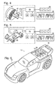
- FIG. 4 is a block diagram of the functional components of the toy vehicle of FIGS. 1 and 2 showing an encoder, a microprocessor, memory, a power supply, control inputs and a display showing a calculated speed.
- FIG. 5 is a block diagram of the functional components of an alternate embodiment of the toy vehicle of FIGS. 1 and 2 showing an accelerometer, a microprocessor, memory, a power supply, control inputs and a display with a calculated speed.
- FIG. 6 is a perspective view showing an alternative configuration of a toy vehicle including LED lights associated with the engine, a display incorporated into the engine area and three user control inputs behind the engine.
- FIG. 7 is a perspective view showing an alternative configuration of a toy vehicle including a connector extending from the vehicle and the connector being plugged into a computer to transfer information between the vehicle and the computer.
- FIG. 8 is a flowchart showing an example of a method of measuring velocity of a toy vehicle, such as the toy vehicle of FIG. 1 .
- Toy vehicle 10 includes a body housing 12 in the form of a car body and a display 14 .
- Display 14 shows a speed corresponding to the vehicle velocity. The speed displayed may not be the actual speed of toy vehicle 10 but may correspond to the speed of a full scale vehicle.
- FIG. 2 a toy vehicle 10 similar to FIG. 1 is shown with body housing 12 cut away to show functional components. Similar numbering is used for clarity in this and subsequent figures as in the previous figure.
- Toy vehicle 10 again includes display 14 and also shows control inputs 16 , a motion sensor 18 , an encoder pattern 20 , a wheel 22 , a microprocessor 24 , a power supply 26 and memory 28 .
- Display 14 , motion sensor 18 , power supply 26 and memory 28 are operably connected to microprocessor 24 .
- Motion sensor 18 may be an accelerometer 30 or a rotary encoder 32 .
- a user playing with toy vehicle 10 may push the vehicle across the floor as fast as possible to achieve the highest possible speed.
- multiple users may race their toys by giving them an initial velocity and releasing them side by side.
- Toy vehicle 10 may travel down an incline to gain speed. Users may try to attain the highest speed or acceleration possible with the data displayed on toy vehicle 10 .
- Rotary encoder 32 may incorporate a light source 34 , a detector 36 and encoder pattern 20 .
- Encoder pattern 20 may be printed on wheel 22 .
- Encoder pattern 20 may comprise contrasting patterns of a black section 38 and a white section 40 .
- Encoder pattern 20 may rotate in front of light source 34 and detector 36 .
- Light from light source 34 may be reflected from the surface of encoder 20 .
- Black section 38 and white section 40 of encoder pattern 20 may reflect different amounts of light.
- Detector 36 may differentiate the amount of light reaching it from light source 34 .
- encoder pattern 20 rotates with wheel 22 .
- white section 40 When white section 40 is proximate to encoder 32 , it reflects more light from source 34 which may cause detector 36 to emit an ‘ON’ signal.
- Black section 38 may reflect less light than white section 40 and may result in detector 36 emitting an ‘OFF’ signal.
- encoder pattern 20 comprises only one white section 40 and one black section 38
- each rotation will result in detector 36 emitting an ‘ON’ signal once.
- Each ‘ON’ signal will indicate one rotation at microprocessor 24 .
- Light source 34 and detector 36 may comprise a single unit.
- Light source 34 may be an LED.
- FIG. 3 an alternate embodiment of rotary encoder 32 is shown including light source 34 , detector 36 and disk 42 .
- Disk 42 may be mounted on an axle 44 and comprise encoder pattern 20 .
- Disk 38 may have clear section 46 and an opaque section 48 .
- Light source or emitter 34 and detector 36 may be mounted on opposite sides of disk 38 such that light only reaches detector 36 when clear section 46 of disk 42 is between source 34 and detector 36 .
- encoder pattern 20 comprises one clear section and one opaque section of disk 38
- each rotation will result in detector 36 emitting an ‘ON’ signal once.
- Each ‘ON’ signal will indicate one rotation.
- Disk 38 may have multiple clear sections separated by opaque sections.
- encoder pattern configurations are examples and should not be construed as limitations. Any encoder pattern configured to operate with rotary encoder 32 may be used and still fall within the scope of this disclosure.
- Microprocessor 24 may count the number of distinct ‘ON’ values transmitted by encoder 32 over a set period of time.
- the wheel circumference may be programmed into microprocessor 24 and the distance traveled may be calculated using the wheel circumference. If the wheel circumference is 2 centimeters (cm) and there are 50 rotations in a second, the distance traveled by toy vehicle 10 is 100 cm and the toy vehicle velocity is 100 cm per second. A velocity of 100 cm per second is equivalent to 3.6 kilometers per hour.
- Microprocessor 24 may be further programmed to multiply this value by the scale of vehicle 10 .
- the speed displayed may be 115 kilometers per hour.
- Microprocessor 24 may further convert this value to other units such as miles per hour and display a speed of 71 miles per hour.
- the reported speed value may be saved into memory 28 .
- the speed value may be shown on display 14 .
- Toy vehicle 10 again includes display 14 , microprocessor 24 , power supply 26 , memory 28 and optical rotary encoder 32 including encoder pattern 20 .
- Rotation of encoder pattern 20 may be detected by rotary encoder 32 and sends a digital signal to microprocessor 24 .
- Microprocessor 24 converts the digital signals to an appropriate value to be sent to display 14 .
- Control inputs 16 may be used to configure microprocessor 24 .
- Toy vehicle 10 may include discrete memory unit 28 .
- motion sensor 18 may be an accelerometer 30 .
- a single axis accelerometer may determine acceleration in one direction, such as by measuring the deflection of a cantilever beam on an integrated circuit chip.
- the chip may include means for measuring the deflection of the beam and transmitting that data from the chip as an electronic signal. Other methods of determining acceleration may also be used.
- Toy vehicle 10 includes display 14 , microprocessor 24 , power supply 26 and accelerometer 30 .
- accelerometer 30 may be supported by housing 12 and configured to measure the acceleration resulting from moving the car forwards and backwards. Data sent from accelerometer 30 may be received by microprocessor 24 . Microprocessor 24 may determine a speed value at any point in time from the measured acceleration and send the speed value to display 14 .
- Microprocessor 24 may convert the acceleration data from accelerator 30 to the required units and format to be sent to display 14 .
- Control inputs 16 may be used to configure the functions of microprocessor 24 .
- Microprocessor 24 may use the information from rotary encoder 32 or accelerometer 30 to determine other toy vehicle performance measures. Microprocessor 24 may determine elapsed time to reach a certain speed. Microprocessor 24 may also determine if the current speed value is higher than a highest or maximum speed value stored in memory and may replace a current speed value in memory.
- Control input 16 may comprise keys.
- the keys may be used to change a mode of play for the toy vehicle or the keys may be used to reset values stored in memory 28 or on microprocessor 24 .
- Keys may include a mode key 38 , a reset key 40 and a unit key 42 .
- Mode key 38 may be used to select from a plurality of modes such as Try Me mode, Speed Test mode, Highest Speed mode, and Time-trial mode.
- Reset key 40 may be used to clear and reset the display contents.
- Unit key 42 may be used to change a display unit of measure.
- the selectable units of display may include M/h (miles per hour), km/h (kilometers per hour), or Rev/s (revolution per second).
- the current speed of the car may be displayed.
- the internal electronics of vehicle 10 may use the information obtained by the rotary encoder 32 or accelerometer 30 to calculate the current speed of the vehicle. If the current speed calculated is higher than the highest speed record, then the current speed may be stored in the highest speed record. Reset key 40 may have no function in this mode.
- the user may select Speed Test Mode using Mode key 38 .
- the Speed Test mode may display the highest speed of the current run. The speed displayed may be different than the speed stored in memory as the highest speed. If the speed displayed in Speed Test Mode is higher than the value stored in memory 28 as the highest speed, the new higher speed value may be replaced with the lower speed value in memory.
- display 14 may show the maximum speed attained.
- the user may press Reset key 40 in this mode to clear the maximum speed record to zero.
- vehicle 10 When vehicle 10 is in Highest Speed Mode toy vehicle 10 may only display memory contents and motion sensor 18 may be turned off.
- the speed value unit of measure may be selected by pressing Unit key 42 .
- pressing the Unit key may change the display from units of Miles per Hour to Kilometers per Hour.
- Time-Trial Mode measures the time it takes for vehicle 10 to reach a predetermined speed, for example the time duration in ms (milliseconds) it takes for vehicle 10 to travel from 0 mph to 100 mph. The time may be displayed in increments of 250 ms per step until the speed of 100 mph is reached.
- electronic motion sensor 18 may be turned on. The time displayed may increment in tenths of a second.
- the decimal point on display 14 may be represented by an underscore. Pressing Reset key 40 may ready the on-board electronics for another time trial by clearing the LCD screen to zero. Unit key 42 may have no function in Time Trial mode.
- vehicle 10 may also include an auto shut down function.
- the internal electronics of toy vehicle 10 may automatically shut down to save power when not in use for a predetermined length of time, such as one minute.
- Display 14 and microprocessor 24 may be turned off on system shut down. Additionally, display 14 may dim when a battery requires replacement or an icon may appear.
- the default mode of play may be Current Speed Mode
- the default display may be 0000
- the default maximum speed recorded may be 0000.
- display 14 has three numeric digits to display speed and at least one icon or set of alphabetic, such as Mph, to indicate the unit of measure of display 14 .
- Alternative embodiments of vehicle 10 may include more digits and icons to display information.
- display 14 consists of four digits used for display of a digital number and an icon in front of the digital number indicating the mode and/or unit in use, such as M/hr, km/hr, etc.
- Display 14 may have four digits for display of a digit number and seven icons for display of unit or mode.
- the mode selected may be displayed in an upper segment of display 14 above the four digit number
- display 14 may display “TRY”, “TEST”, “MAX”, and “0-100” respectively.
- the display unit selected may be displayed in a side segment to the right of the four digit number.
- display 14 may show “MPH”, “KPH”, and “REV” respectively.
- a toy vehicle 10 is shown in an alternate configuration with a representation of an engine visible and LED lights as part of the engine representation.
- the engine representation also incorporates display 14 .
- Control inputs 16 may be located behind the engine.
- a toy vehicle 10 is shown with a USB connector 44 located at the rear portion of vehicle 10 .
- Vehicle 10 may include body 12 and display 14 .
- USB connector 44 may be used to connect to a computer 200 .
- Data from vehicle 10 may be uploaded to computer 200 , and data from computer 200 may be downloaded to vehicle 10 .
- Computer 200 may display data uploaded from vehicle 10 , calculated information uploaded from vehicle 10 , or calculated information determined using data uploaded from vehicle 10 .
- vehicle 10 may include a speaker. Vehicle 10 may download audio files from computer 200 and play the audio files during acceleration or at other times during play.
- vehicle 10 may record multiple measurements of vehicle performance and save the measurements to memory 28 .
- vehicle 10 may record speed of vehicle 10 every second for 20 seconds as vehicle 10 travels along a track.
- the results may be downloaded from memory 28 to computer 200 .
- Computer 200 may create a graphical chart displaying the collected speed values.
- Connector 44 may be a different kind of connector or comprise a cable.
- Connector 44 could be a wireless link such as a link using infrared or radio communication.
- Command inputs may comprise more or fewer buttons.
- display configurations, play modes and encoders described here are examples only and should not be considered limitations. Other configurations than those presented which perform similar functions are within the scope of this disclosure.
- Box 302 includes accelerating a toy.
- Box 304 includes measuring toy motion from onboard the toy, for example by a rotary encoder (such as an optical rotary encoder), an accelerometer, and so forth, as detailed above. In one example, toy motion in only one direction may be measured.
- Box 306 includes calculating toy velocity from the measurements, as explained above.
- Box 308 includes converting the calculated velocity to a scaled velocity, for example by multiplying the calculated velocity to a scaled vehicle velocity by multiplying the calculated velocity by a factor corresponding to the scale of the vehicle.
- Box 310 includes displaying the scaled vehicle velocity on the toy vehicle, such as on a LCD display.
- methods may further include further steps, indicated in boxes 312 , 314 , and 316 , respectively, of calculating a plurality of toy vehicle velocities during acceleration, determining a maximum toy vehicle velocity from the calculated toy vehicle velocities, and selecting a display mode to display the determined maximum toy vehicle velocity value.
- Another optional step of storing multiple calculated toy vehicle velocity values in memory onboard the toy vehicle is indicated in box 318 .
- Optional steps of connecting a microprocessor to a computer and transferring data between the toy vehicle and the computer are indicated in boxes 320 , 322 .
- Other methods may include fewer or more steps than those shown in 300 .
- some methods may include displaying the calculated toy vehicle velocity without converting the calculated velocity to a scaled toy vehicle velocity.
- Such methods, or other methods may include steps in a different order than as illustrated in FIG. 8 . All of such variations are considered to be within the scope of this disclosure.
Abstract
A toy vehicle that measures and displays performance characteristics is presented. The toy vehicle may be configured to measure performance of the toy, such as speed or acceleration, and display a value for the performance characteristic. A display for showing the performance values may be mounted on the body of the toy vehicle. Movement of the toy vehicle may be measured using an accelerometer. The toy vehicle may determine the number of wheel rotations in a set period of time using a rotary encoder. The value of the performance characteristic may be output to a microprocessor onboard the toy vehicle. The microprocessor may use the value in calculations and the result of the calculations, such as a scaled speed value, may be shown on the display screen.
Description
This application claims priority to U.S. Provisional Application Ser. No. 60/687,375, filed Jun. 3, 2005, and entitled “Toy Vehicle with On-Board Electronics,” incorporated herein by reference.
The present disclosure relates generally to toy vehicles with on-board electronics, and more specifically to toy vehicles incorporating electronics to record and display data related to the performance of the toy vehicle.
Examples of known toy vehicles are disclosed in U.S. Pat. Nos. 2,800,329, 2,896,708, 3,546,668, 3,618,397, 3,652,937, 3,942,114, 4,237,648, 4,247,107, 4,265,047, 4,280,300, 4,292,758, 4,330,127, 4,349,196, 4,364,566, 4,479,650, 4,451,911, 4,946,416, 4,964,837, 5,306,197, 5,637,996, 5,692,956, 5,855,483, 5,928,058, 6,155,928, 6,200,219, 6,293,798, 6,354,842, 6,461,238, 6,688,985, D426,215, D492,685 and published U.S. patent application Ser. Nos. US2001/0045978, US2002/0142701, US2002/0187725, US2003/0188594, US2004/0032395, US2004/0077285, US2004/0224740, US2005/0064936, WO199615837, WO2002078810, WO2004033247. The disclosures of all of these patents and publications are incorporated herein by reference.
A toy vehicle of the present disclosure may be rolled by children on flat surfaces, down inclines or along flexible tracks and may not use motors or other power sources for motion. A toy vehicle may include electronic sensors such as rotary optical encoders or accelerometers that monitor motion of the vehicle or monitor motion of a wheel of the vehicle. The toy vehicle may be used to simulate racing and the displayed data may be used to compare vehicle speed with other similar toy vehicles or with other runs of the same vehicle.
The data recorded by the sensors may be used to perform calculations relating to the motion or speed of the vehicle. The recorded data and/or results of the calculations may be made available to the user The data may be displayed on a Liquid Crystal Display (“LCD”) as part of the toy, a remote LCD screen, through Light Emitting Diodes (“LEDs”), through an audio output such as a speaker, or even through a conventional computer output device by plugging the vehicle into the computer or by plugging removable memory from the vehicle into the computer.
Values calculated and displayed may include speed, distance traveled, length of time of travel and acceleration (“G Force”). Some embodiments of the toy vehicle may include keys or control inputs that allow the user to change what information is displayed.
The advantages of the present invention will be understood more readily after a consideration of the drawings and the Detailed Description of the Preferred Embodiment.
Referring to FIG. 1 , a user 8 is shown rolling a toy vehicle 10 on the floor. Toy vehicle 10 includes a body housing 12 in the form of a car body and a display 14. Display 14 shows a speed corresponding to the vehicle velocity. The speed displayed may not be the actual speed of toy vehicle 10 but may correspond to the speed of a full scale vehicle.
Referring to FIG. 2 , a toy vehicle 10 similar to FIG. 1 is shown with body housing 12 cut away to show functional components. Similar numbering is used for clarity in this and subsequent figures as in the previous figure. Toy vehicle 10 again includes display 14 and also shows control inputs 16, a motion sensor 18, an encoder pattern 20, a wheel 22, a microprocessor 24, a power supply 26 and memory 28. Display 14, motion sensor 18, power supply 26 and memory 28 are operably connected to microprocessor 24. Motion sensor 18 may be an accelerometer 30 or a rotary encoder 32.
A user playing with toy vehicle 10 may push the vehicle across the floor as fast as possible to achieve the highest possible speed. In some applications, multiple users may race their toys by giving them an initial velocity and releasing them side by side. Toy vehicle 10 may travel down an incline to gain speed. Users may try to attain the highest speed or acceleration possible with the data displayed on toy vehicle 10.
Where encoder pattern 20 is on the surface of wheel 22, encoder pattern 20 rotates with wheel 22. When white section 40 is proximate to encoder 32, it reflects more light from source 34 which may cause detector 36 to emit an ‘ON’ signal. Black section 38 may reflect less light than white section 40 and may result in detector 36 emitting an ‘OFF’ signal.
Where encoder pattern 20 comprises only one white section 40 and one black section 38, each rotation will result in detector 36 emitting an ‘ON’ signal once. Each ‘ON’ signal will indicate one rotation at microprocessor 24. Light source 34 and detector 36 may comprise a single unit. Light source 34 may be an LED.
In FIG. 3 , an alternate embodiment of rotary encoder 32 is shown including light source 34, detector 36 and disk 42. Disk 42 may be mounted on an axle 44 and comprise encoder pattern 20. Disk 38 may have clear section 46 and an opaque section 48. Light source or emitter 34 and detector 36 may be mounted on opposite sides of disk 38 such that light only reaches detector 36 when clear section 46 of disk 42 is between source 34 and detector 36.
Where encoder pattern 20 comprises one clear section and one opaque section of disk 38, each rotation will result in detector 36 emitting an ‘ON’ signal once. Each ‘ON’ signal will indicate one rotation. Disk 38 may have multiple clear sections separated by opaque sections.
These encoder pattern configurations are examples and should not be construed as limitations. Any encoder pattern configured to operate with rotary encoder 32 may be used and still fall within the scope of this disclosure.
Referring to FIG. 4 , a block diagram of the functional components of toy vehicle 10 is shown. Toy vehicle 10 again includes display 14, microprocessor 24, power supply 26, memory 28 and optical rotary encoder 32 including encoder pattern 20. Rotation of encoder pattern 20 may be detected by rotary encoder 32 and sends a digital signal to microprocessor 24. Microprocessor 24 converts the digital signals to an appropriate value to be sent to display 14. Control inputs 16 may be used to configure microprocessor 24. Toy vehicle 10 may include discrete memory unit 28.
In an alternate configuration, motion sensor 18 may be an accelerometer 30. A single axis accelerometer may determine acceleration in one direction, such as by measuring the deflection of a cantilever beam on an integrated circuit chip. The chip may include means for measuring the deflection of the beam and transmitting that data from the chip as an electronic signal. Other methods of determining acceleration may also be used.
Referring to FIG. 5 , a block diagram shows the functional components of an alternate configuration of toy vehicle 10. Toy vehicle 10 includes display 14, microprocessor 24, power supply 26 and accelerometer 30.
In this example, accelerometer 30 may be supported by housing 12 and configured to measure the acceleration resulting from moving the car forwards and backwards. Data sent from accelerometer 30 may be received by microprocessor 24. Microprocessor 24 may determine a speed value at any point in time from the measured acceleration and send the speed value to display 14.
In Try Me mode, the current speed of the car may be displayed. In this mode, the internal electronics of vehicle 10 may use the information obtained by the rotary encoder 32 or accelerometer 30 to calculate the current speed of the vehicle. If the current speed calculated is higher than the highest speed record, then the current speed may be stored in the highest speed record. Reset key 40 may have no function in this mode.
The user may select Speed Test Mode using Mode key 38. The Speed Test mode may display the highest speed of the current run. The speed displayed may be different than the speed stored in memory as the highest speed. If the speed displayed in Speed Test Mode is higher than the value stored in memory 28 as the highest speed, the new higher speed value may be replaced with the lower speed value in memory.
In Highest Speed Mode, display 14 may show the maximum speed attained. The user may press Reset key 40 in this mode to clear the maximum speed record to zero. When vehicle 10 is in Highest Speed Mode toy vehicle 10 may only display memory contents and motion sensor 18 may be turned off.
The speed value unit of measure may be selected by pressing Unit key 42. For example, pressing the Unit key may change the display from units of Miles per Hour to Kilometers per Hour.
Time-Trial Mode measures the time it takes for vehicle 10 to reach a predetermined speed, for example the time duration in ms (milliseconds) it takes for vehicle 10 to travel from 0 mph to 100 mph. The time may be displayed in increments of 250 ms per step until the speed of 100 mph is reached. When vehicle 10 is in Time Trial Mode, electronic motion sensor 18 may be turned on. The time displayed may increment in tenths of a second.
The decimal point on display 14 may be represented by an underscore. Pressing Reset key 40 may ready the on-board electronics for another time trial by clearing the LCD screen to zero. Unit key 42 may have no function in Time Trial mode.
Some embodiments of vehicle 10 may also include an auto shut down function. The internal electronics of toy vehicle 10 may automatically shut down to save power when not in use for a predetermined length of time, such as one minute. Display 14 and microprocessor 24 may be turned off on system shut down. Additionally, display 14 may dim when a battery requires replacement or an icon may appear.
In some embodiments of vehicle 10, there may be default game play settings and default display settings when the toy is first turned on. For example, the default mode of play may be Current Speed Mode, the default display may be 0000, and the default maximum speed recorded may be 0000.
Referring again to the example depicted in FIG. 1 , display 14 has three numeric digits to display speed and at least one icon or set of alphabetic, such as Mph, to indicate the unit of measure of display 14. Alternative embodiments of vehicle 10 may include more digits and icons to display information. In an alternate embodiment of vehicle 10, display 14 consists of four digits used for display of a digital number and an icon in front of the digital number indicating the mode and/or unit in use, such as M/hr, km/hr, etc. Display 14 may have four digits for display of a digit number and seven icons for display of unit or mode.
The mode selected may be displayed in an upper segment of display 14 above the four digit number When in Try Me mode, Speed Test mode, Highest Speed mode or Time Trial mode, display 14 may display “TRY”, “TEST”, “MAX”, and “0-100” respectively. The display unit selected may be displayed in a side segment to the right of the four digit number. When in miles per hour, kilometers per hour, or revolutions per minute, display 14 may show “MPH”, “KPH”, and “REV” respectively.
Referring to FIG. 6 , a toy vehicle 10 is shown in an alternate configuration with a representation of an engine visible and LED lights as part of the engine representation. The engine representation also incorporates display 14. Control inputs 16 may be located behind the engine.
Referring to FIG. 7 , a toy vehicle 10 is shown with a USB connector 44 located at the rear portion of vehicle 10. Vehicle 10 may include body 12 and display 14. USB connector 44 may be used to connect to a computer 200. Data from vehicle 10 may be uploaded to computer 200, and data from computer 200 may be downloaded to vehicle 10. Computer 200 may display data uploaded from vehicle 10, calculated information uploaded from vehicle 10, or calculated information determined using data uploaded from vehicle 10.
In an alternate embodiment, vehicle 10 may include a speaker. Vehicle 10 may download audio files from computer 200 and play the audio files during acceleration or at other times during play.
In an alternate embodiment, vehicle 10 may record multiple measurements of vehicle performance and save the measurements to memory 28. For example, vehicle 10 may record speed of vehicle 10 every second for 20 seconds as vehicle 10 travels along a track. The results may be downloaded from memory 28 to computer 200. Computer 200 may create a graphical chart displaying the collected speed values.
These configurations are presented as examples and should not be construed as limitations. Connector 44 may be a different kind of connector or comprise a cable. Connector 44 could be a wireless link such as a link using infrared or radio communication. Command inputs may comprise more or fewer buttons. Similarly, display configurations, play modes and encoders described here are examples only and should not be considered limitations. Other configurations than those presented which perform similar functions are within the scope of this disclosure.
The foregoing disclosure details several possible methods of measuring the velocity of a reduced-scale toy vehicle, such as toy vehicle 10. Some examples of such methods are shown in FIG. 8 and indicated generally at 300. Box 302 includes accelerating a toy. Box 304 includes measuring toy motion from onboard the toy, for example by a rotary encoder (such as an optical rotary encoder), an accelerometer, and so forth, as detailed above. In one example, toy motion in only one direction may be measured. Box 306 includes calculating toy velocity from the measurements, as explained above. Box 308 includes converting the calculated velocity to a scaled velocity, for example by multiplying the calculated velocity to a scaled vehicle velocity by multiplying the calculated velocity by a factor corresponding to the scale of the vehicle. Box 310 includes displaying the scaled vehicle velocity on the toy vehicle, such as on a LCD display.
Optionally, methods may further include further steps, indicated in boxes 312, 314, and 316, respectively, of calculating a plurality of toy vehicle velocities during acceleration, determining a maximum toy vehicle velocity from the calculated toy vehicle velocities, and selecting a display mode to display the determined maximum toy vehicle velocity value. Another optional step of storing multiple calculated toy vehicle velocity values in memory onboard the toy vehicle is indicated in box 318. Optional steps of connecting a microprocessor to a computer and transferring data between the toy vehicle and the computer are indicated in boxes 320, 322.
Other methods may include fewer or more steps than those shown in 300. For example, some methods may include displaying the calculated toy vehicle velocity without converting the calculated velocity to a scaled toy vehicle velocity. Such methods, or other methods, may include steps in a different order than as illustrated in FIG. 8 . All of such variations are considered to be within the scope of this disclosure.
It is believed that the disclosure set forth above encompasses multiple distinct inventions with independent utility. While each of these inventions has been disclosed in its preferred form, the specific embodiments thereof as disclosed and illustrated herein are not to be considered in a limiting sense as numerous variations are possible. The subject matter of the inventions includes all novel and non-obvious combinations and subcombinations of the various elements, features, functions and/or properties disclosed herein. Similarly, where any claim recites “a” or “a first” element or the equivalent thereof, such claim should be understood to include incorporation of one or more such elements, neither requiring nor excluding two or more such elements.
Inventions embodied in various combinations and subcombinations of features, functions, elements, and/or properties may be claimed through presentation of new claims in this or a related application. Such new claims, whether they are directed to a different invention or directed to the same invention, whether different, broader, narrower or equal in scope to the original claims, are also regarded as included within the subject matter of the inventions of the present disclosure.
Claims (25)
1. A toy vehicle comprising:
a housing configured to resemble a reduced-scale vehicle;
at least one freely rotatable wheel supporting the housing and configured to rotate when the vehicle moves along an external surface;
a display disposed on an exterior surface of the housing for displaying a velocity value;
a rotary encoder configured to count rotations of the freely rotatable wheel and output encoder data representative of the rotation count; and
a microprocessor configured to calculate toy vehicle velocity from the encoder data and to send a velocity value to the display.
2. The toy vehicle of claim 1 where the rotary encoder includes an encoder pattern configured to rotate with the at least one wheel, and the rotary encoder counts wheel rotation.
3. The toy vehicle of claim 1 where the display is a liquid crystal display.
4. The toy vehicle of claim 1 where the value displayed is the velocity of the toy multiplied by a scale factor corresponding to the reduced scale of the toy vehicle.
5. The toy vehicle of claim 1 further comprising memory operably connected to the microprocessor.
6. The toy vehicle of claim 1 further comprising a connector, operably connected to the microprocessor, configured to connect the microprocessor to a personal computer and transfer data between the microprocessor and personal computer.
7. The toy vehicle of claim 1 further comprising at least one control input.
8. A toy vehicle comprising:
a housing configured to resemble a reduced-scale vehicle;
a display disposed on an exterior surface of the housing for displaying a speed;
an accelerometer for measuring vehicle motion; and
a microprocessor configured to:
calculate toy vehicle velocity from measured vehicle motion; and
send a velocity value to the display.
9. The toy vehicle of claim 8 where the accelerometer is a Micro Electro Mechanical System.
10. The toy vehicle of claim 8 further comprising memory for storing program instructions and values.
11. The toy vehicle of claim 8 further comprising a connector configured to connect the microprocessor to a personal computer.
12. The toy vehicle of claim 8 further comprising at least one control input.
13. A speedometer to be used in a reduced-scale toy vehicle having a body supported on at least one freely rotatable wheel that rotates when the vehicle is moved along a support surface, the speedometer comprising:
an optical rotary encoder, including an encoder pattern, configured to count rotation of the freely rotatable wheel;
control inputs;
a display on the toy vehicle;
a power source; and
a microprocessor, operably connected to the control inputs, the encoder, the display and the power source, the microprocessor configured to determine and display a value based on counted wheel rotation.
14. The toy speedometer of claim 13 where the display is a liquid crystal display.
15. The toy speedometer of claim 13 where the value displayed is the speed of the toy vehicle multiplied by a scale factor corresponding to the reduced scale of the toy vehicle.
16. The toy speedometer of claim 13 further comprising memory operably connected to the microprocessor.
17. The toy speedometer of claim 13 further comprising a connector configured to connect the microprocessor to a personal computer for transferring data between the microprocessor and personal computer.
18. A method of measuring velocity of a reduced-scale toy vehicle, comprising:
accelerating a reduced-scale toy vehicle;
measuring toy motion from onboard the toy vehicle;
calculating toy vehicle velocity from the measurements;
converting the calculated velocity to a scaled vehicle velocity by multiplying the calculated velocity by a factor corresponding to the reduced scale of the toy vehicle; and
displaying the scaled vehicle velocity on the toy vehicle.
19. The velocity measuring method of claim 18 where toy motion is measured by an accelerometer.
20. The velocity measuring method of claim 18 where toy motion is measured by an optical rotary encoder.
21. The velocity measuring method of claim 18 where toy motion in only one direction is measured.
22. The velocity measuring method of claim 18 further comprising calculating a plurality of toy vehicle velocities during acceleration, determining a maximum toy vehicle velocity from the calculated toy vehicle velocities, and selecting a display mode to display the determined maximum toy vehicle velocity value.
23. The velocity measuring method of claim 18 further comprising storing a toy vehicle velocity value in memory onboard the toy vehicle.
24. The velocity measuring method of claim 18 further comprising storing multiple calculated toy vehicle velocity values in memory onboard the toy vehicle.
25. The velocity measuring method of claim 18 further comprising:
connecting a microprocessor to a computer; and
transferring data between the toy vehicle and the computer.
Priority Applications (7)
| Application Number | Priority Date | Filing Date | Title |
|---|---|---|---|
| US11/422,033 US7275975B2 (en) | 2005-06-03 | 2006-06-02 | Toy vehicle with on-board electronics |
| CA2610477A CA2610477C (en) | 2005-06-03 | 2006-06-05 | Toy vehicle with on-board electronics |
| DE112006001450T DE112006001450T5 (en) | 2005-06-03 | 2006-06-05 | Toy vehicle with on-board electronics |
| PCT/US2006/021687 WO2006133061A2 (en) | 2005-06-03 | 2006-06-05 | Toy vehicle with on-board electronics |
| CN2006800247737A CN101218003B (en) | 2005-06-03 | 2006-06-05 | Toy vehicle with on-board electronics |
| MX2007015024A MX2007015024A (en) | 2005-06-03 | 2006-06-05 | Toy vehicle with on-board electronics. |
| GB0723296A GB2441459B (en) | 2005-06-03 | 2006-06-05 | Toy vehicle with on-board electronics |
Applications Claiming Priority (2)
| Application Number | Priority Date | Filing Date | Title |
|---|---|---|---|
| US68737505P | 2005-06-03 | 2005-06-03 | |
| US11/422,033 US7275975B2 (en) | 2005-06-03 | 2006-06-02 | Toy vehicle with on-board electronics |
Publications (2)
| Publication Number | Publication Date |
|---|---|
| US20070004311A1 US20070004311A1 (en) | 2007-01-04 |
| US7275975B2 true US7275975B2 (en) | 2007-10-02 |
Family
ID=37498984
Family Applications (1)
| Application Number | Title | Priority Date | Filing Date |
|---|---|---|---|
| US11/422,033 Active US7275975B2 (en) | 2005-06-03 | 2006-06-02 | Toy vehicle with on-board electronics |
Country Status (7)
| Country | Link |
|---|---|
| US (1) | US7275975B2 (en) |
| CN (1) | CN101218003B (en) |
| CA (1) | CA2610477C (en) |
| DE (1) | DE112006001450T5 (en) |
| GB (1) | GB2441459B (en) |
| MX (1) | MX2007015024A (en) |
| WO (1) | WO2006133061A2 (en) |
Cited By (5)
| Publication number | Priority date | Publication date | Assignee | Title |
|---|---|---|---|---|
| US20070249422A1 (en) * | 2005-10-11 | 2007-10-25 | Zeetoo, Inc. | Universal Controller For Toys And Games |
| US20090179856A1 (en) * | 2008-01-11 | 2009-07-16 | Lorraine Morgan Scott | Special Mouse |
| US8662953B1 (en) | 2011-03-16 | 2014-03-04 | Jeannie M. Tarr | Toy car apparatus |
| US8876572B2 (en) | 2011-08-29 | 2014-11-04 | Mattel, Inc. | Toy vehicle launching ramp and landing ramp |
| US11471783B2 (en) | 2019-04-16 | 2022-10-18 | Mattel, Inc. | Toy vehicle track system |
Families Citing this family (3)
| Publication number | Priority date | Publication date | Assignee | Title |
|---|---|---|---|---|
| US8417383B2 (en) * | 2006-05-31 | 2013-04-09 | Irobot Corporation | Detecting robot stasis |
| JP5995299B1 (en) * | 2015-07-14 | 2016-09-21 | 株式会社バンダイ | toy |
| US11224820B2 (en) | 2016-10-31 | 2022-01-18 | Lego A/S | Vehicle comprising an electric motor and a method of starting an electric motor for propulsion of a vehicle |
Citations (42)
| Publication number | Priority date | Publication date | Assignee | Title |
|---|---|---|---|---|
| US2800329A (en) | 1954-06-28 | 1957-07-23 | William C Tinsley | Toy control panel |
| US2896708A (en) | 1956-06-22 | 1959-07-28 | Hubley Mfg Company | Toy speedometer |
| US3546668A (en) | 1967-09-11 | 1970-12-08 | Frank C Legler | Talking speedometer |
| US3618397A (en) | 1969-11-26 | 1971-11-09 | Mattel Inc | Speedometer for toy vehicles |
| US3652937A (en) | 1970-11-02 | 1972-03-28 | William L Garrott | Speed and fault indicator for a model vehicle |
| US3942114A (en) | 1974-10-15 | 1976-03-02 | Keeling William E | Speed detector and indicator for DC motors |
| US4237648A (en) | 1979-01-24 | 1980-12-09 | Diker Moe Associates | Moving toy figure |
| US4247107A (en) | 1979-01-19 | 1981-01-27 | California R & D Center | Electronically controlled roadrace system with sound generator |
| US4265047A (en) | 1979-02-09 | 1981-05-05 | Marvin Glass & Associates | Vehicle instrumentation and control apparatus |
| US4280300A (en) | 1980-02-08 | 1981-07-28 | Marvin Glass & Associates | Toy vehicle |
| US4292758A (en) | 1980-01-30 | 1981-10-06 | Marvin Glass & Associates | Jet toy boat |
| US4330127A (en) | 1981-03-02 | 1982-05-18 | Brand Derek A | Toy racing car game accessory |
| US4349196A (en) | 1980-02-08 | 1982-09-14 | Smith Engineering | Computer control toy track system |
| US4364566A (en) | 1979-09-29 | 1982-12-21 | Hermann Neuhierl | Game apparatus with toy vehicles |
| US4451911A (en) | 1982-02-03 | 1984-05-29 | Mattel, Inc. | Interactive communicating toy figure device |
| US4479650A (en) | 1982-04-26 | 1984-10-30 | Hermann Neuhierl | Toy-racing express motor road |
| US4946416A (en) | 1989-11-01 | 1990-08-07 | Innova Development Corporation | Vehicle with electronic sounder and direction sensor |
| US4964837A (en) | 1989-02-16 | 1990-10-23 | Collier Harry B | Radio controlled model vehicle having coordinated sound effects system |
| US5306197A (en) | 1990-09-10 | 1994-04-26 | Tomy Company, Limited | Key action, moveable toy |
| WO1996015837A1 (en) | 1994-11-21 | 1996-05-30 | Compaq Computer Corporation | Interactive play with a computer |
| US5637996A (en) | 1993-02-05 | 1997-06-10 | Link Group International | Toy system with movable vehicles |
| US5692956A (en) | 1996-02-09 | 1997-12-02 | Mattel, Inc. | Combination computer mouse and game play control |
| US5928058A (en) | 1996-06-07 | 1999-07-27 | Francis; Geoffrey V. | Slot car and mechanism for guiding same |
| USD426215S (en) | 1999-07-20 | 2000-06-06 | Whalen Patrick F | Race car computer mouse |
| US6155928A (en) | 1998-05-19 | 2000-12-05 | The Coca-Cola Company | Modular portable gaming simulator systems and methods |
| US6200219B1 (en) | 1998-06-10 | 2001-03-13 | Elliot Rudell | Toy vehicles with integral motion sensitive game display |
| US6293798B1 (en) | 1999-11-10 | 2001-09-25 | Skyline Products | System and method for an RC controller and software |
| US20010045978A1 (en) | 2000-04-12 | 2001-11-29 | Mcconnell Daniel L. | Portable personal wireless interactive video device and method of using the same |
| US6354842B1 (en) | 2000-03-09 | 2002-03-12 | Massachusetts Institute Of Technology | Rolling toy with motion recording and playback capability |
| US20020142701A1 (en) | 2001-03-30 | 2002-10-03 | Rosenberg Louis B. | Haptic remote control for toys |
| US6461238B1 (en) | 2000-08-03 | 2002-10-08 | Rehco, Llc | Portable simulation game apparatus |
| US20020187725A1 (en) | 2001-06-06 | 2002-12-12 | Konami Corporation | Play extension system and program for the same |
| US20030010545A1 (en) * | 2001-04-20 | 2003-01-16 | Seiko Epson Corporation | Direction control device of control target |
| US20030188594A1 (en) | 2002-04-03 | 2003-10-09 | Immersion Corporation | Haptic shifting devices |
| US6688985B2 (en) | 2001-02-07 | 2004-02-10 | Mattel, Inc. | Electrically controlled racing game with information and control center |
| US20040032395A1 (en) | 1996-11-26 | 2004-02-19 | Goldenberg Alex S. | Haptic feedback effects for control knobs and other interface devices |
| WO2004033247A2 (en) | 2002-10-04 | 2004-04-22 | Tesla Capital, Llc | Electrical systems for electric powered vehicles |
| US20040077285A1 (en) | 2002-04-22 | 2004-04-22 | Bonilla Victor G. | Method, apparatus, and system for simulating visual depth in a concatenated image of a remote field of action |
| USD492685S1 (en) | 2003-07-30 | 2004-07-06 | Stephen J. Vlcek | Computer input device |
| US20040224740A1 (en) | 2000-08-02 | 2004-11-11 | Ball Timothy James | Simulation system |
| US20050064936A1 (en) | 2000-07-07 | 2005-03-24 | Pryor Timothy R. | Reconfigurable control displays for games, toys, and other applications |
| US20060183405A1 (en) * | 2005-02-15 | 2006-08-17 | Mathews David K | System for monitoring operation of a toy vehicle |
Family Cites Families (5)
| Publication number | Priority date | Publication date | Assignee | Title |
|---|---|---|---|---|
| US4325199A (en) * | 1980-10-14 | 1982-04-20 | Mcedwards Timothy K | Engine sound simulator |
| CN2277072Y (en) * | 1996-08-08 | 1998-03-25 | 段平凡 | Timing velometer of toy car |
| US6071166A (en) * | 1998-04-21 | 2000-06-06 | Toymax Inc. | Light shooting and detecting toy figures |
| US6089951A (en) * | 1999-01-29 | 2000-07-18 | Mattel, Inc. | Toy vehicle and trackset having lap-counting feature |
| CN1129464C (en) * | 1999-11-15 | 2003-12-03 | 赵舜培 | Turn number counter for competitive track vehicle |
-
2006
- 2006-06-02 US US11/422,033 patent/US7275975B2/en active Active
- 2006-06-05 MX MX2007015024A patent/MX2007015024A/en active IP Right Grant
- 2006-06-05 DE DE112006001450T patent/DE112006001450T5/en not_active Withdrawn
- 2006-06-05 GB GB0723296A patent/GB2441459B/en not_active Expired - Fee Related
- 2006-06-05 WO PCT/US2006/021687 patent/WO2006133061A2/en active Application Filing
- 2006-06-05 CA CA2610477A patent/CA2610477C/en not_active Expired - Fee Related
- 2006-06-05 CN CN2006800247737A patent/CN101218003B/en not_active Expired - Fee Related
Patent Citations (45)
| Publication number | Priority date | Publication date | Assignee | Title |
|---|---|---|---|---|
| US2800329A (en) | 1954-06-28 | 1957-07-23 | William C Tinsley | Toy control panel |
| US2896708A (en) | 1956-06-22 | 1959-07-28 | Hubley Mfg Company | Toy speedometer |
| US3546668A (en) | 1967-09-11 | 1970-12-08 | Frank C Legler | Talking speedometer |
| US3618397A (en) | 1969-11-26 | 1971-11-09 | Mattel Inc | Speedometer for toy vehicles |
| US3652937A (en) | 1970-11-02 | 1972-03-28 | William L Garrott | Speed and fault indicator for a model vehicle |
| US3942114A (en) | 1974-10-15 | 1976-03-02 | Keeling William E | Speed detector and indicator for DC motors |
| US4247107A (en) | 1979-01-19 | 1981-01-27 | California R & D Center | Electronically controlled roadrace system with sound generator |
| US4237648A (en) | 1979-01-24 | 1980-12-09 | Diker Moe Associates | Moving toy figure |
| US4265047A (en) | 1979-02-09 | 1981-05-05 | Marvin Glass & Associates | Vehicle instrumentation and control apparatus |
| US4364566A (en) | 1979-09-29 | 1982-12-21 | Hermann Neuhierl | Game apparatus with toy vehicles |
| US4292758A (en) | 1980-01-30 | 1981-10-06 | Marvin Glass & Associates | Jet toy boat |
| US4349196A (en) | 1980-02-08 | 1982-09-14 | Smith Engineering | Computer control toy track system |
| US4280300A (en) | 1980-02-08 | 1981-07-28 | Marvin Glass & Associates | Toy vehicle |
| US4330127A (en) | 1981-03-02 | 1982-05-18 | Brand Derek A | Toy racing car game accessory |
| US4451911A (en) | 1982-02-03 | 1984-05-29 | Mattel, Inc. | Interactive communicating toy figure device |
| US4479650A (en) | 1982-04-26 | 1984-10-30 | Hermann Neuhierl | Toy-racing express motor road |
| US4964837A (en) | 1989-02-16 | 1990-10-23 | Collier Harry B | Radio controlled model vehicle having coordinated sound effects system |
| US4964837B1 (en) | 1989-02-16 | 1993-09-14 | B. Collier Harry | Radio controlled model vehicle having coordinated sound effects system |
| US4946416A (en) | 1989-11-01 | 1990-08-07 | Innova Development Corporation | Vehicle with electronic sounder and direction sensor |
| US5306197A (en) | 1990-09-10 | 1994-04-26 | Tomy Company, Limited | Key action, moveable toy |
| US5637996A (en) | 1993-02-05 | 1997-06-10 | Link Group International | Toy system with movable vehicles |
| US5855483A (en) | 1994-11-21 | 1999-01-05 | Compaq Computer Corp. | Interactive play with a computer |
| WO1996015837A1 (en) | 1994-11-21 | 1996-05-30 | Compaq Computer Corporation | Interactive play with a computer |
| US5692956A (en) | 1996-02-09 | 1997-12-02 | Mattel, Inc. | Combination computer mouse and game play control |
| US5928058A (en) | 1996-06-07 | 1999-07-27 | Francis; Geoffrey V. | Slot car and mechanism for guiding same |
| US20040032395A1 (en) | 1996-11-26 | 2004-02-19 | Goldenberg Alex S. | Haptic feedback effects for control knobs and other interface devices |
| US6155928A (en) | 1998-05-19 | 2000-12-05 | The Coca-Cola Company | Modular portable gaming simulator systems and methods |
| US6200219B1 (en) | 1998-06-10 | 2001-03-13 | Elliot Rudell | Toy vehicles with integral motion sensitive game display |
| USD426215S (en) | 1999-07-20 | 2000-06-06 | Whalen Patrick F | Race car computer mouse |
| US6293798B1 (en) | 1999-11-10 | 2001-09-25 | Skyline Products | System and method for an RC controller and software |
| US6354842B1 (en) | 2000-03-09 | 2002-03-12 | Massachusetts Institute Of Technology | Rolling toy with motion recording and playback capability |
| US20010045978A1 (en) | 2000-04-12 | 2001-11-29 | Mcconnell Daniel L. | Portable personal wireless interactive video device and method of using the same |
| US20050064936A1 (en) | 2000-07-07 | 2005-03-24 | Pryor Timothy R. | Reconfigurable control displays for games, toys, and other applications |
| US20040224740A1 (en) | 2000-08-02 | 2004-11-11 | Ball Timothy James | Simulation system |
| US6461238B1 (en) | 2000-08-03 | 2002-10-08 | Rehco, Llc | Portable simulation game apparatus |
| US6688985B2 (en) | 2001-02-07 | 2004-02-10 | Mattel, Inc. | Electrically controlled racing game with information and control center |
| US20020142701A1 (en) | 2001-03-30 | 2002-10-03 | Rosenberg Louis B. | Haptic remote control for toys |
| WO2002078810A1 (en) | 2001-03-30 | 2002-10-10 | Immersion Corporation | Haptic remote control for toys |
| US20030010545A1 (en) * | 2001-04-20 | 2003-01-16 | Seiko Epson Corporation | Direction control device of control target |
| US20020187725A1 (en) | 2001-06-06 | 2002-12-12 | Konami Corporation | Play extension system and program for the same |
| US20030188594A1 (en) | 2002-04-03 | 2003-10-09 | Immersion Corporation | Haptic shifting devices |
| US20040077285A1 (en) | 2002-04-22 | 2004-04-22 | Bonilla Victor G. | Method, apparatus, and system for simulating visual depth in a concatenated image of a remote field of action |
| WO2004033247A2 (en) | 2002-10-04 | 2004-04-22 | Tesla Capital, Llc | Electrical systems for electric powered vehicles |
| USD492685S1 (en) | 2003-07-30 | 2004-07-06 | Stephen J. Vlcek | Computer input device |
| US20060183405A1 (en) * | 2005-02-15 | 2006-08-17 | Mathews David K | System for monitoring operation of a toy vehicle |
Cited By (6)
| Publication number | Priority date | Publication date | Assignee | Title |
|---|---|---|---|---|
| US20070249422A1 (en) * | 2005-10-11 | 2007-10-25 | Zeetoo, Inc. | Universal Controller For Toys And Games |
| US8142287B2 (en) * | 2005-10-11 | 2012-03-27 | Zeemote Technology Inc. | Universal controller for toys and games |
| US20090179856A1 (en) * | 2008-01-11 | 2009-07-16 | Lorraine Morgan Scott | Special Mouse |
| US8662953B1 (en) | 2011-03-16 | 2014-03-04 | Jeannie M. Tarr | Toy car apparatus |
| US8876572B2 (en) | 2011-08-29 | 2014-11-04 | Mattel, Inc. | Toy vehicle launching ramp and landing ramp |
| US11471783B2 (en) | 2019-04-16 | 2022-10-18 | Mattel, Inc. | Toy vehicle track system |
Also Published As
| Publication number | Publication date |
|---|---|
| CN101218003A (en) | 2008-07-09 |
| MX2007015024A (en) | 2008-04-22 |
| WO2006133061A3 (en) | 2007-02-08 |
| GB2441459B (en) | 2010-03-03 |
| GB0723296D0 (en) | 2008-01-09 |
| DE112006001450T5 (en) | 2008-04-17 |
| WO2006133061A2 (en) | 2006-12-14 |
| GB2441459A (en) | 2008-03-05 |
| CN101218003B (en) | 2012-05-09 |
| CA2610477C (en) | 2011-03-08 |
| US20070004311A1 (en) | 2007-01-04 |
| CA2610477A1 (en) | 2006-12-14 |
Similar Documents
| Publication | Publication Date | Title |
|---|---|---|
| US7275975B2 (en) | Toy vehicle with on-board electronics | |
| KR100762286B1 (en) | Treadmill system | |
| US7495549B2 (en) | Integrated power, lighting, and instrumentation system for bicycles | |
| CN102198316B (en) | Multi-sensor montoring of athletic performance | |
| US6200219B1 (en) | Toy vehicles with integral motion sensitive game display | |
| WO2002011838A1 (en) | Handheld driving simulation game apparatus | |
| KR100475622B1 (en) | Game extension system and computer readable recording medium recording program therefor | |
| JP3806285B2 (en) | Light-emitting toy and body condition recording / judgment system using light-emitting toy | |
| JP2019501002A (en) | Stationary ergometric exercise device | |
| KR20020094887A (en) | Toy system | |
| JPH10510357A (en) | Opto-mechanical device for measuring line distance | |
| ES2225254T3 (en) | TOY CONSTRUCTION ASSEMBLY WITH A MEASUREMENT SENSOR. | |
| CN201583546U (en) | Bicycle detecting device | |
| JPH11197268A (en) | Traveling simulation device of bicycle | |
| KR101759096B1 (en) | Indoor bicycle that uses a magnetic brake and system | |
| US20090179856A1 (en) | Special Mouse | |
| KR100782916B1 (en) | Treadmill system and control method thereof | |
| GB2452119A (en) | Toy navigation device, e.g. sat-nav | |
| CN1250941C (en) | Assembled walking counter | |
| CN210728656U (en) | Emitter | |
| WO2023166946A1 (en) | Traveling toy | |
| CN220125504U (en) | Light-emitting device | |
| CN211364808U (en) | Children fitness detection system applied to scooter | |
| US20220395761A1 (en) | Drag racing stability management for a model vehicle | |
| KR100440670B1 (en) | The display method and device that using the afterimage effect in the moving object. |
Legal Events
| Date | Code | Title | Description |
|---|---|---|---|
| AS | Assignment |
Owner name: MATTEL, INC., CALIFORNIA Free format text: ASSIGNMENT OF ASSIGNORS INTEREST;ASSIGNORS:TRAGESER, MARK;WEI, ALAN;WONG, ANGUS;AND OTHERS;REEL/FRAME:018300/0862;SIGNING DATES FROM 20060602 TO 20060901 |
|
| STCF | Information on status: patent grant |
Free format text: PATENTED CASE |
|
| FPAY | Fee payment |
Year of fee payment: 4 |
|
| FPAY | Fee payment |
Year of fee payment: 8 |
|
| MAFP | Maintenance fee payment |
Free format text: PAYMENT OF MAINTENANCE FEE, 12TH YEAR, LARGE ENTITY (ORIGINAL EVENT CODE: M1553); ENTITY STATUS OF PATENT OWNER: LARGE ENTITY Year of fee payment: 12 |