US7280666B2 - Moveable device component with acoustic porting - Google Patents
Moveable device component with acoustic porting Download PDFInfo
- Publication number
- US7280666B2 US7280666B2 US10/973,231 US97323104A US7280666B2 US 7280666 B2 US7280666 B2 US 7280666B2 US 97323104 A US97323104 A US 97323104A US 7280666 B2 US7280666 B2 US 7280666B2
- Authority
- US
- United States
- Prior art keywords
- acoustic
- component
- microphone
- dual purpose
- acoustic port
- Prior art date
- Legal status (The legal status is an assumption and is not a legal conclusion. Google has not performed a legal analysis and makes no representation as to the accuracy of the status listed.)
- Expired - Fee Related, expires
Links
- 230000037361 pathway Effects 0.000 claims abstract description 11
- 230000009977 dual effect Effects 0.000 claims description 51
- 238000000034 method Methods 0.000 claims description 12
- 230000005236 sound signal Effects 0.000 claims description 8
- 230000008878 coupling Effects 0.000 claims description 5
- 238000010168 coupling process Methods 0.000 claims description 5
- 238000005859 coupling reaction Methods 0.000 claims description 5
- 230000001413 cellular effect Effects 0.000 abstract description 51
- 238000012545 processing Methods 0.000 description 9
- 238000010586 diagram Methods 0.000 description 4
- 238000013461 design Methods 0.000 description 2
- 230000002411 adverse Effects 0.000 description 1
- 230000009286 beneficial effect Effects 0.000 description 1
- 230000005540 biological transmission Effects 0.000 description 1
- 230000001419 dependent effect Effects 0.000 description 1
- 238000010348 incorporation Methods 0.000 description 1
- 239000004973 liquid crystal related substance Substances 0.000 description 1
- 239000000463 material Substances 0.000 description 1
- 239000002184 metal Substances 0.000 description 1
- 238000012986 modification Methods 0.000 description 1
- 230000004048 modification Effects 0.000 description 1
- 230000002085 persistent effect Effects 0.000 description 1
- 230000035945 sensitivity Effects 0.000 description 1
- 230000001052 transient effect Effects 0.000 description 1
- 238000013022 venting Methods 0.000 description 1
- 230000000007 visual effect Effects 0.000 description 1
- XLYOFNOQVPJJNP-UHFFFAOYSA-N water Substances O XLYOFNOQVPJJNP-UHFFFAOYSA-N 0.000 description 1
Images


Classifications
-
- H—ELECTRICITY
- H04—ELECTRIC COMMUNICATION TECHNIQUE
- H04R—LOUDSPEAKERS, MICROPHONES, GRAMOPHONE PICK-UPS OR LIKE ACOUSTIC ELECTROMECHANICAL TRANSDUCERS; DEAF-AID SETS; PUBLIC ADDRESS SYSTEMS
- H04R1/00—Details of transducers, loudspeakers or microphones
- H04R1/20—Arrangements for obtaining desired frequency or directional characteristics
- H04R1/32—Arrangements for obtaining desired frequency or directional characteristics for obtaining desired directional characteristic only
- H04R1/34—Arrangements for obtaining desired frequency or directional characteristics for obtaining desired directional characteristic only by using a single transducer with sound reflecting, diffracting, directing or guiding means
- H04R1/342—Arrangements for obtaining desired frequency or directional characteristics for obtaining desired directional characteristic only by using a single transducer with sound reflecting, diffracting, directing or guiding means for microphones
-
- H—ELECTRICITY
- H04—ELECTRIC COMMUNICATION TECHNIQUE
- H04R—LOUDSPEAKERS, MICROPHONES, GRAMOPHONE PICK-UPS OR LIKE ACOUSTIC ELECTROMECHANICAL TRANSDUCERS; DEAF-AID SETS; PUBLIC ADDRESS SYSTEMS
- H04R2499/00—Aspects covered by H04R or H04S not otherwise provided for in their subgroups
- H04R2499/10—General applications
- H04R2499/11—Transducers incorporated or for use in hand-held devices, e.g. mobile phones, PDA's, camera's
Definitions
- the present invention generally relates to the field of acoustic systems, and more particularly relates to acoustic systems with acoustic pathways through device components.
- flip phone which can be used as a conventional cellular phone or in a high audio mode that includes both speaker phone operations as well as walkie-talkie modes (also known as dispatch modes).
- walkie-talkie modes also known as dispatch modes.
- the flip part of the phone is able to be closed and then physically blocks the microphone mounted in the base of the phone. It is desirable for such a flip phone to have the same microphone acoustic performance regardless of the position of the flip part of the phone.
- the high audio operation of such a flip phone should not appreciably vary when the flip part is open or closed.
- Some conventional designs provide an acoustic pathway in the form of a large gap or a groove between the flip part and the base of the phone that acts as an acoustic channel for the audio signal.
- An acoustic pathway can also be provided between the two parts of the closed flip phone by placing bumpers in the area between the two flip phone parts so that an air gap is provided when the flip phone is closed. Providing these gaps or groves enhances acoustic performance by preventing blockage of the microphone when the flip is closed.
- bumpers add thickness to the phone when it is in the closed position, which limits a designer's ability to produce the ever smaller, and especially thinner, acoustic devices such as flip cellular phones that are in demand.
- the use of bumpers can also increase the number of parts in the phone assembly. Furthermore, these bumpers and groves can cosmetically detract from the phone.
- an acoustic system includes a first component having a microphone and a second component that is moveable relative to the first component.
- the second component is also able to be positioned in at least a first position and a second position relative to the first component.
- the second component also has a first wall and a second wall with the second wall being opposite the first wall.
- the acoustic system further has at least one acoustic transducer that is affixed to the second component.
- the second component also includes at least one acoustic port that is configured to pass a sound pressure signal, which is generated by the acoustic transducer, through a first wall of the second component.
- the second component further has at least one dual purpose acoustic port that is located on the second wall of the second component and that is configured to pass an ambient sound pressure signal that enters the at least one acoustic port to the microphone.
- a method for coupling a sound pressure signal includes providing a first component that has a microphone and providing a second component. The first component and the second component are movable with respect to each other into at least a first position and a second position. The method further includes providing an acoustic transducer mounted on the second component. The acoustic transducer is capable of producing a sound pressure signal. The method also includes providing at least one acoustic port that is configured to pass the sound pressure signal through a first wall of the second component. The method also includes passing an ambient sound pressure signal that enters the at least one acoustic port through at least one dual purpose acoustic port on a second wall of the second component to the microphone.
- FIG. 1 illustrates a cellular flip-type phone according to an exemplary embodiment of the present invention in an open position.
- FIG. 2 illustrates the cellular flip-type phone of FIG. 1 in a closed position.
- FIG. 3 illustrates an exploded view for part of the closed cellular flip-type phone of FIG. 2 .
- FIG. 4 illustrates a side cut away view for the closed cellular phone of FIG. 2 .
- FIG. 5 illustrates a bottom cut away view for the closed cellular phone of FIG. 2 .
- FIG. 6 illustrates a processing flow diagram for coupling a sound pressure signal according to an exemplary embodiment of the present invention.
- FIG. 7 illustrates a block diagram of a cellular phone incorporating an exemplary embodiment of the present invention.
- FIG. 1 illustrates a cellular flip-type phone 100 according to an exemplary embodiment of the present invention in an open position.
- the cellular flip-type phone 100 includes a first component that is a phone base 104 , and a second component that is a flip part 102 .
- the flip part 102 is a cover part in this exemplary embodiment.
- the phone base 104 and the flip part 102 are moveable relative to each other around a hinge 114 .
- Further embodiments of the present invention incorporate two or more components that move relative to each other in various ways, such as a so-called “slider” phone where a first component is a base part and a second component is a cover part that slides along the first component to expand and contract the size of the phone and expose and conceal various elements of the phone.
- the phone base 104 and flip part 102 in this exemplary embodiment include electronic circuits, as are described below, that support wireless voice communications.
- the phone base 104 of this exemplary embodiment includes a keypad 106 to allow entry of phone numbers and other phone control information for the phone.
- the phone base 104 of this exemplary embodiment further includes a microphone contained within a microphone protrusion 108 that protrudes above the neighboring surface of the phone base 104 , as is discussed in more detail below.
- the flip part 102 is connected to the phone base 104 by hinge 114 .
- the flip part 102 is shown in this illustration in the open, or second, position.
- a closed position, or first position, is illustrated and described below.
- a flip front side 120 is illustrated in this view of the cellular flip-type phone 100 .
- the flip part 102 has a display 110 that in this exemplary embodiment is able to display alpha-numeric and graphical data that is either communicated over a wireless link or that is used to control the operation of the exemplary cellular phone 100 .
- the flip part 102 further includes a dual purpose acoustic port 112 that is recessed into the flip front side 120 and that has a recess wall 122 .
- An acoustic transducer described below, is located behind the dual purpose acoustic port 112 and generates sound pressure signals that correspond to, for example, audio signals received by the cellular phone 100 over a wireless link.
- the configuration of the dual purpose acoustic port 112 and microphone protrusion 108 allow the open cellular flip-type phone 100 to be held along the face of the user to facilitate wireless audio communications.
- the recess of the dual purpose acoustic port 112 accepts the protruding microphone protrusion 108 .
- Further embodiments of the present invention incorporate dual purpose acoustic ports that protrude above the flip front side 120 and have microphones that are recessed into the phone base 104 .
- Yet further embodiments of the present invention include microphones that form substantially closed acoustic pathways with other structures between their first component and second components.
- the open cellular flip-type phone 100 is able to be used in a mode in which a relatively low level acoustic signal is produced through the dual purpose acoustic port 112 that allows the dual purpose acoustic port 112 to be held near the user's ear.
- a further operation mode for the open cellular flip-type phone 100 includes a high level audio mode in which a separate speaker, illustrated below in FIG. 4 , is used to produce a higher level audio output signal.
- the cellular phone 100 is then able to be held away from the user's ear and face and used in either of the familiar “speakerphone” or simplex voice communications modes.
- Microphone within microphone protrusion 108 is also generally operated with increased sensitivity in these modes in order to facilitate operation of the cellular phone 100 in the high level audio mode. Operation in the high level audio mode can be used when the cellular phone is communicating in a speakerphone wherein voice signals are simultaneously transmitted and received over a wireless link, or in a simplex mode wherein the operator alternately selects one of transmitting and receiving voice signals over the wireless link. Simplex mode is controlled in the exemplary cellular phone 100 by pressing the Push-To-Talk (PTT) button 116 . When the PTT button 116 is pressed, acoustic signals that are detected by microphone within microphone protrusion 108 are transmitted over the wireless link and no audio signals are received.
- PTT Push-To-Talk
- audio signals received over the wireless link are produced through a high audio level speaker (illustrated below in FIG. 4 and located on the underside of phone base 104 in this exemplary embodiment) so that they can be heard by the user.
- the volume of the audio signal produced by the cellular phone 100 can be adjusted by volume control buttons 118 .
- FIG. 2 illustrates the cellular flip-type phone 100 of FIG. 1 in the closed position.
- the closed cellular flip-type phone 100 has its flip part 102 rotated about hinge 114 , relative to the open cellular flip-type phone discussed above, so as to lie along the top of the phone base 104 and to be in a first position.
- An outer flip part side 204 is illustrated in this view of the cellular flip-type phone 100 .
- the outer flip part side 204 is the side of the flip part 102 that is opposite the front side 120 of the flip part 102 , described above.
- the outer flip part side 204 includes an outer side acoustic port 202 that allows sound pressure signals from an acoustic transducer, which is internal to the flip part 102 in this exemplary embodiment and is discussed below, to be ported through the outer flip part side 204 .
- Providing an acoustic port on the outer flip part side 204 is beneficial in smaller cellular phones that have a correspondingly smaller flip part 102 since the reduced internal spatial volume of the closed phone can adversely impact sound quality if such an acoustic port is not provided. Larger flip-type cellular phones are better able to adequately operate without an acoustic port on the outer flip part 204 side because they have larger internal spatial volume when closed. Incorporation of the outer side acoustic port 202 on the outer flip part side 204 advantageously provides improved acoustic performance when using a smaller flip part 102 .
- the closed cellular flip-type phone 100 further identifies two sectional views, a sectional view 4 - 4 and a sectional view 5 - 5 , which are described in detail below.
- FIG. 3 illustrates an exploded view 300 for part of the closed cellular flip-type phone 100 of FIG. 2 .
- the phone base 104 , microphone protrusion 108 and the back of the flip front side 120 of the flip part 102 are shown for the cellular phone 100 .
- a flip part inner support 302 is shown removed from the part supporting the front side 120 of the flip part 102 .
- the flip part support 302 has a number of acoustic ports to support the operation of the acoustic system of the exemplary cellular phone 100 .
- An acoustic transducer mounting area 312 accepts an acoustic transducer that is not shown in this illustration for clarity, but that is described below.
- the acoustic transducer mounting area 312 has a first acoustic transducer port 308 and a second acoustic transducer port 310 to pass sound pressure signals generated by a transducer placed in the acoustic transducer mounting area 312 .
- Sound pressure signals generated by a mounted transducer pass through the first acoustic transducer port 308 and the second transducer port 310 and through the dual purpose acoustic port 112 when the flip part 102 is in the open, or second, position. Sound pressure signals generated by the mounted acoustic transducer also pass through outer side acoustic port 202 .
- the exploded view of FIG. 3 further illustrates the sound pressure signal path that is formed from the outer side acoustic port 202 to the microphone protrusion 108 when the flip part 102 is in its closed, or first, position.
- sound pressure signals are able to enter the outer side acoustic port 202 , pass through the first internal dual purpose acoustic port 304 and the second internal dual purpose acoustic port 306 , and then pass on through the dual purpose acoustic port 112 and on through to the microphone protrusion 108 .
- This arrangement provides a path from the outer side acoustic port 202 on the outer flip part side 204 to the microphone protrusion 108 , thereby providing enhanced acoustic performance when the flip part 102 is in its closed, or first position. It can also be seen from this figure that microphone protrusion 108 protrudes into the recess formed by acoustic port 112 in this exemplary embodiment.
- the acoustic path formed by the outer side acoustic port 202 , the first internal dual purpose acoustic port 304 and the second internal dual purpose acoustic port 306 , and the dual purpose acoustic port 112 is additionally used by sound pressure signals generated by an acoustic transducer when the flip part 102 is held relatively tightly to a users ear.
- the acoustic path through the dual use acoustic ports ensures a consistent acoustic performance for the user without regard to how the flip part 102 is held to the ear of the user. This characteristic advantageously provides a leak tolerant design by venting pressure.
- the “dual purpose” ports are given that name in this specification due to the use of these ports to conduct sound pressure signals that are generated by an acoustic transducer as well as to conduct sound pressure signals received from ambient sources, such as a user's voice, from the ambient area to the microphone protrusion 108 .
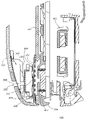
- FIG. 4 illustrates a closed cellular phone side cut away view 400 for the closed cellular phone 100 of FIG. 2 .
- the side cut away view 400 corresponds to the sectional view through 4 - 4 of FIG. 2 .
- the flip part 102 is shown to include the flip part inner support 302 with an acoustic transducer mounting area 312 .
- An acoustic transducer 406 such as an electromagnetic speaker in the exemplary embodiment, is shown to be attached at the acoustic transducer mounting area 312 , which is part of the flip part 102 .
- flip part 102 is a moveable component of the acoustic system of cellular phone 100 .
- the front of the acoustic transducer 406 is shown to be facing and in proximity to the dual purpose acoustic port 112 .
- the rear of the acoustic transducer 406 is mounted on the acoustic transducer mounting area 312 so that sound generated by the acoustic transducer 406 is ported through the first acoustic transducer port 308 (as illustrated in FIG. 3 ) and the second acoustic transducer port 310 (as illustrated in FIG. 3 ).
- the first acoustic transducer port 308 and the second acoustic transducer port 310 are not visible in the perspective of this figure, but are located in the flip part internal support 302 , as shown above in FIG. 3 .
- Sound pressure signals generated by the acoustic transducer 406 of the exemplary embodiment pass through the first acoustic transducer port 308 and the second acoustic transducer port 310 and are then ported through the outer side acoustic port 202 .
- the outer side acoustic port 202 is an acoustic port configured to pass sound pressure signals generated by the acoustic transducer 406 through a first wall of the flip part 102 , which is a moveable component of cell phone 100 .
- the second internal dual purpose acoustic port 306 as well as the first internal dual purpose acoustic port 304 (which is behind the second internal dual purpose acoustic port 306 in the perspective of this figure but is not explicitly visible in this figure), form an acoustical path between the outer side acoustic port 202 and the dual purpose acoustic port 112 .
- ambient sound pressure signals arriving and entering through outer side acoustic port 202 pass through the second internal dual purpose acoustic port 306 and first internal dual purpose acoustic port 304 and then through the dual purpose acoustic port 112 and are delivered directly to microphone protrusion 108 .
- the flip part 102 is shown to be folded closed along the phone base 104 so that the flip front side 120 is in proximity to the front of the phone base 104 .
- the microphone protrusion 108 is shown to be protruding into the recess formed for the dual purpose acoustic port 112 .
- This configuration forms a substantially closed acoustic pathway 404 between the dual purpose acoustic port 112 , which is a dual purpose acoustic port in this exemplary embodiment, and the microphone protrusion 108 .
- This substantially closed acoustic pathway 404 is also partially formed by the flip front side 120 in the exemplary embodiment.
- a microphone cartridge 402 which is part of microphone protrusion 108 in this exemplary embodiment.
- a high output speaker 410 is also illustrated in this side cut away view.
- High output speaker 410 is used for various purposes within the cellular phone 100 , such as for call notification ringing as well as for generating acoustic output when the cellular phone is operating in a high level audio mode, as described above, in either a simplex or duplex operational mode.
- the acoustic transducer 406 does not operate when the flip part 102 of the cellular phone 100 is in its closed, or first, position, as is illustrated in this side cut away view.
- High output speaker 410 is instead used to generate audio output in this configuration.
- FIG. 5 illustrates a bottom cut away view 500 for the cellular phone 100 of FIG. 2 .
- the bottom cut away view 500 corresponds to the sectional view through line 5 - 5 of FIG. 2 .
- the cut away view 500 illustrates the position of microphone cartridge 402 and the microphone protrusion 108 that are mounted in the phone base 104 .
- the bottom cut away view 500 also illustrates the acoustic transducer 406 , and the flip part internal support 302 that are located in the flip part 102 .
- the bottom cut away view 500 further illustrates a felt pad 506 that lines the back of the flip front side 120 .
- Felt pad 506 is used in the exemplary embodiment in order to, for example, prevent foreign material from entering the phone housing.
- the felt pad 506 helps reduce the impact of metal shavings, which are attracted to the magnet within the acoustic transducer 406 and reduce the entry of water into the phone's case.
- Microphone acoustic paths 502 are illustrated to show the path of sound pressure signals that enter the outer side acoustic port 202 , propagate through the first acoustic transducer port 308 and the second acoustic transducer port 310 , and continue on to reach the dual purpose acoustic port 112 . These sound pressure signals then continue on through the substantially closed acoustic pathway 404 and arrive at microphone protrusion 108 . These direct microphone acoustic paths 502 provide for enhanced acoustic performance of the microphone cartridge 402 when the flip part 102 of the flip-type phone 100 is in its closed position.
- Speaker acoustic paths 504 are illustrated to show the path of sound pressure signals that propagate from the acoustic transducer 406 , through the first acoustic transducer port 308 and the second acoustic transducer port 310 , and through the outer side acoustic port 202 .
- the exemplary embodiment of the present invention does not operate the acoustic transducer 406 when the flip part is in a closed position, as illustrated in this bottom cut away view, but this acoustic path is shown in this figure for comparison to the microphone acoustic path 502 .
- the microphone acoustic path 502 and the speaker acoustic path 504 are not identical, they do share a porting of acoustic signals through the outer side acoustic port 202 .
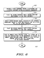
- FIG. 6 illustrates a processing flow diagram 600 for coupling a sound pressure signal according to an exemplary embodiment of the present invention.
- the coupling of a sound pressure signal begins by providing, at step 602 , a first component having a microphone and a second component having an acoustic transducer.
- the phone base 104 corresponds to the first component and the flip part 102 corresponds to the second component.
- the processing continues by placing, at step 604 , the second component into a second position with respect to the first component.
- the open position of the cell phone 100 corresponds to this second position.
- the processing then passes, at step 606 , a sound pressure signal generated by the acoustic transducer 406 through at least one acoustic port in a first wall of the second component.
- this step passes the sound pressure signal through at least the outer side acoustic port 202 .
- the processing places, at step 608 , the second component into a first position with respect to the first component. In the above described exemplary embodiment, the closed position corresponds to this first position.
- the processing then passes, at step 610 , an ambient sound pressure signal that enters the at least one acoustic port to the microphone protrusion 108 by passing the ambient sound pressure signal through at least one dual purpose acoustic port 112 on a second wall of the second component.
- FIG. 7 illustrates a block diagram of a cellular phone 700 incorporating an exemplary embodiment of the present invention.
- the cellular phone 700 includes an RF antenna 702 , an RF receiver 704 and an RF transmitter 706 .
- the RF transmitter 706 and RF receiver 704 are connected to the RF antenna 702 in order to support bi-directional RF communications.
- the cellular phone 700 is able to simultaneously transmit and receive voice and/or data signals.
- the RF receiver 704 provides voice data to an audio processor 708 and the audio processor 708 provides voice data to the RF transmitter 706 to implement voice communications.
- the audio processor 708 obtains voice signals from microphone cartridge 406 and generates audio signals that are provided to the acoustic transducer 402 or to the high output speaker 410 , dependent upon the operational mode of the cellular phone.
- the RF receiver 704 , RF transmitter 706 , audio processor 708 , microphone cartridge 406 and acoustic transducer 402 operate to communicate voice signals to and from the cellular phone 700 .
- the cellular phone 700 includes a controller 716 that controls the operation of the cellular phone in the exemplary embodiment.
- Controller 716 is connected to the various components of the cellular phone 700 via control bus 722 .
- Controller 716 communicates data to external devices (not shown), such as a base station and/or a server, through a wireless link.
- Controller 716 provides data to and accepts data from data processor 714 .
- Data processor 714 of the exemplary embodiment performs communications processing necessary to implement over-the-air data communications to and from external devices.
- Data processor 714 provides data for transmission to the RF transmitter 706 and accepts received data from the RF receiver 704 .
- Controller 716 provides visual display data to the user through display 110 .
- Display 110 of the exemplary embodiment is a Liquid Crystal Display that is able to display alphanumeric and graphical data.
- Controller 716 also accepts user input from keypad 106 .
- Keypad 106 is similar to a conventional cellular phone keypad and has buttons to accept user input in order to support operation of the cellular phone 700 .
- the cellular phone 700 further includes non-volatile memory 726 .
- Non-volatile memory 726 stores program data and more persistent data for use by the controller 716 . Data stored in non-volatile memory 726 of the exemplary embodiment can be changed under control of controller 716 if called for by particular processing performed by the controller 716 .
- the cellular phone 700 further contains volatile memory 724 . Volatile memory 724 is able to store transient data for use by processing and/or calculations performed by the controller 716 .
Abstract
Description
Claims (17)
Priority Applications (1)
| Application Number | Priority Date | Filing Date | Title |
|---|---|---|---|
| US10/973,231 US7280666B2 (en) | 2004-10-26 | 2004-10-26 | Moveable device component with acoustic porting |
Applications Claiming Priority (1)
| Application Number | Priority Date | Filing Date | Title |
|---|---|---|---|
| US10/973,231 US7280666B2 (en) | 2004-10-26 | 2004-10-26 | Moveable device component with acoustic porting |
Publications (2)
| Publication Number | Publication Date |
|---|---|
| US20060088179A1 US20060088179A1 (en) | 2006-04-27 |
| US7280666B2 true US7280666B2 (en) | 2007-10-09 |
Family
ID=36206208
Family Applications (1)
| Application Number | Title | Priority Date | Filing Date |
|---|---|---|---|
| US10/973,231 Expired - Fee Related US7280666B2 (en) | 2004-10-26 | 2004-10-26 | Moveable device component with acoustic porting |
Country Status (1)
| Country | Link |
|---|---|
| US (1) | US7280666B2 (en) |
Cited By (7)
| Publication number | Priority date | Publication date | Assignee | Title |
|---|---|---|---|---|
| US20070019820A1 (en) * | 2005-06-29 | 2007-01-25 | Zurek Robert A | Communication device with single output audio transducer |
| US20080069384A1 (en) * | 2006-09-18 | 2008-03-20 | Samsung Electronics Co. Ltd. | Speaker device for portable terminal |
| US20080130931A1 (en) * | 2006-11-30 | 2008-06-05 | Motorola, Inc. | Attachable external acoustic chamber for a mobile device |
| US8180075B2 (en) | 2007-04-26 | 2012-05-15 | Motorola Mobility, Inc. | Arrangement for variable bass reflex cavities |
| US20120231849A1 (en) * | 2011-03-09 | 2012-09-13 | Kyocera Corporation | Mobile electronic device |
| US8971974B2 (en) | 2011-04-28 | 2015-03-03 | Nflukz, Llc | Cover for hand-held electronic device |
| US9800969B2 (en) | 2013-10-22 | 2017-10-24 | Nokia Technologies Oy | Speaker back cavity |
Families Citing this family (1)
| Publication number | Priority date | Publication date | Assignee | Title |
|---|---|---|---|---|
| TWI354455B (en) * | 2007-08-21 | 2011-12-11 | Asustek Comp Inc | Communication device |
Citations (9)
| Publication number | Priority date | Publication date | Assignee | Title |
|---|---|---|---|---|
| US5732331A (en) * | 1995-01-12 | 1998-03-24 | Ericsson Inc. | Portable radio having a detachable flip portion |
| US6134336A (en) * | 1998-05-14 | 2000-10-17 | Motorola, Inc. | Integrated speaker assembly of a portable electronic device |
| US20010029198A1 (en) * | 1997-07-08 | 2001-10-11 | Seiji Miyashita | Microphone assembly for a portable telephone with a foldable flap element |
| US20040018862A1 (en) * | 2002-07-22 | 2004-01-29 | Jon Godston | Self operating opening mechanism for use in a hand-held electronic device |
| US20050020327A1 (en) * | 2003-07-23 | 2005-01-27 | Samsung Electronics Co., Ltd. | Speaker-up type portable terminal |
| US20050137000A1 (en) * | 2003-12-22 | 2005-06-23 | Toh Kok W. | Rotatable latching device for a housing of a portable electronic device |
| US20060148540A1 (en) * | 2003-02-12 | 2006-07-06 | Matsushita Electric Industrial Co., Ltd. | Portable terminal device |
| US7092745B1 (en) * | 1999-10-08 | 2006-08-15 | Nokia Mobile Phones Limited | Portable electronics device with variable sound output |
| US7103395B2 (en) * | 2001-10-11 | 2006-09-05 | Nec Corporation | Folding mobile terminal device capable of receiving and transmitting sound while folded |
-
2004
- 2004-10-26 US US10/973,231 patent/US7280666B2/en not_active Expired - Fee Related
Patent Citations (9)
| Publication number | Priority date | Publication date | Assignee | Title |
|---|---|---|---|---|
| US5732331A (en) * | 1995-01-12 | 1998-03-24 | Ericsson Inc. | Portable radio having a detachable flip portion |
| US20010029198A1 (en) * | 1997-07-08 | 2001-10-11 | Seiji Miyashita | Microphone assembly for a portable telephone with a foldable flap element |
| US6134336A (en) * | 1998-05-14 | 2000-10-17 | Motorola, Inc. | Integrated speaker assembly of a portable electronic device |
| US7092745B1 (en) * | 1999-10-08 | 2006-08-15 | Nokia Mobile Phones Limited | Portable electronics device with variable sound output |
| US7103395B2 (en) * | 2001-10-11 | 2006-09-05 | Nec Corporation | Folding mobile terminal device capable of receiving and transmitting sound while folded |
| US20040018862A1 (en) * | 2002-07-22 | 2004-01-29 | Jon Godston | Self operating opening mechanism for use in a hand-held electronic device |
| US20060148540A1 (en) * | 2003-02-12 | 2006-07-06 | Matsushita Electric Industrial Co., Ltd. | Portable terminal device |
| US20050020327A1 (en) * | 2003-07-23 | 2005-01-27 | Samsung Electronics Co., Ltd. | Speaker-up type portable terminal |
| US20050137000A1 (en) * | 2003-12-22 | 2005-06-23 | Toh Kok W. | Rotatable latching device for a housing of a portable electronic device |
Cited By (16)
| Publication number | Priority date | Publication date | Assignee | Title |
|---|---|---|---|---|
| US7961900B2 (en) * | 2005-06-29 | 2011-06-14 | Motorola Mobility, Inc. | Communication device with single output audio transducer |
| US20110212754A1 (en) * | 2005-06-29 | 2011-09-01 | Motorola Mobility, Inc. | Flip-Type Communication Device with a Single Output Audio Transducer |
| US20070019820A1 (en) * | 2005-06-29 | 2007-01-25 | Zurek Robert A | Communication device with single output audio transducer |
| US20080069384A1 (en) * | 2006-09-18 | 2008-03-20 | Samsung Electronics Co. Ltd. | Speaker device for portable terminal |
| US8098868B2 (en) * | 2006-09-18 | 2012-01-17 | Samsung Electronics Co., Ltd. | Speaker device for portable terminal |
| US8577069B2 (en) | 2006-11-30 | 2013-11-05 | Motorola Mobility Llc | Attachable external acoustic chambers for a mobile device |
| US20080130931A1 (en) * | 2006-11-30 | 2008-06-05 | Motorola, Inc. | Attachable external acoustic chamber for a mobile device |
| US8098867B2 (en) | 2006-11-30 | 2012-01-17 | Motorola Mobility, Inc. | Attachable external acoustic chamber for a mobile device |
| US8180075B2 (en) | 2007-04-26 | 2012-05-15 | Motorola Mobility, Inc. | Arrangement for variable bass reflex cavities |
| US20120231849A1 (en) * | 2011-03-09 | 2012-09-13 | Kyocera Corporation | Mobile electronic device |
| US8700101B2 (en) * | 2011-03-09 | 2014-04-15 | Kyocera Corporation | Mobile electronic device |
| US9094932B2 (en) | 2011-03-09 | 2015-07-28 | Kyocera Corporation | Mobile electronic device |
| US9521651B2 (en) | 2011-03-09 | 2016-12-13 | Kyocera Corporation | Mobile electronic device |
| US8971974B2 (en) | 2011-04-28 | 2015-03-03 | Nflukz, Llc | Cover for hand-held electronic device |
| US9800969B2 (en) | 2013-10-22 | 2017-10-24 | Nokia Technologies Oy | Speaker back cavity |
| US10027784B2 (en) | 2013-10-22 | 2018-07-17 | Nokia Technologies Oy | Speaker back cavity |
Also Published As
| Publication number | Publication date |
|---|---|
| US20060088179A1 (en) | 2006-04-27 |
Similar Documents
| Publication | Publication Date | Title |
|---|---|---|
| JP4261581B2 (en) | Speaker unit and portable terminal including the speaker unit | |
| US6052464A (en) | Telephone set having a microphone for receiving or an earpiece for generating an acoustic signal via a keypad | |
| US6137883A (en) | Telephone set having a microphone for receiving an acoustic signal via keypad | |
| KR101636461B1 (en) | A hole construction for inputing and outputing sound of acoustic appliance in portable terminal | |
| US6002949A (en) | Handset with a single transducer for handset and handsfree functionality | |
| EP2238769B1 (en) | Acoustic reconfiguration devices and methods | |
| US7068782B2 (en) | Communications devices with receiver earpieces and methods therefor | |
| WO2019228245A1 (en) | Mobile terminal control method and mobile terminal | |
| US20100054492A1 (en) | Leak-Tolerant Earspeakers, Related Portable Electronic Devices and Methods of Operating the Same | |
| US8290179B2 (en) | Multiple-use acoustic port | |
| US20050069164A1 (en) | Microphone system for a communication device | |
| GB2355128A (en) | Single transducer for hands-free and private use has separate acoustic paths with different attenuations | |
| JPH08139794A (en) | Portable telephone mechanism with built-in variable capacity receiver | |
| CN103200288A (en) | Communication device with single output audio transducer | |
| US20040081325A1 (en) | Waterproof acoustic structure applicable in conjunction with speaker | |
| JP2005006205A (en) | Mobile terminal | |
| KR101202236B1 (en) | Portable phone having speaker | |
| KR100689486B1 (en) | Spearker for mobile phone using resonance space | |
| EP1897351B1 (en) | A speaker apparatus combining earpiece and hands free functions | |
| US7280666B2 (en) | Moveable device component with acoustic porting | |
| CN102204274A (en) | Electronic devices including substrate mounted acoustic actuators and related methods and mobile radiotelephones | |
| US20060140433A1 (en) | Dual sided ear cup | |
| KR101669020B1 (en) | Speaker module for portable terminal and execution method in speaker phone mode using it | |
| CN212064357U (en) | Receiver and terminal | |
| US20060018499A1 (en) | Acoustic resonator/diffuser system and method |
Legal Events
| Date | Code | Title | Description |
|---|---|---|---|
| AS | Assignment |
Owner name: MOTOROLA, INC., ILLINOIS Free format text: ASSIGNMENT OF ASSIGNORS INTEREST;ASSIGNORS:GUYOT, NICOLAS E.;FRIEDMAN, JOSEPH M.;REEL/FRAME:015939/0310 Effective date: 20041020 |
|
| AS | Assignment |
Owner name: MOTOROLA MOBILITY, INC, ILLINOIS Free format text: ASSIGNMENT OF ASSIGNORS INTEREST;ASSIGNOR:MOTOROLA, INC;REEL/FRAME:025673/0558 Effective date: 20100731 |
|
| FPAY | Fee payment |
Year of fee payment: 4 |
|
| AS | Assignment |
Owner name: MOTOROLA MOBILITY LLC, ILLINOIS Free format text: CHANGE OF NAME;ASSIGNOR:MOTOROLA MOBILITY, INC.;REEL/FRAME:029216/0282 Effective date: 20120622 |
|
| AS | Assignment |
Owner name: GOOGLE TECHNOLOGY HOLDINGS LLC, CALIFORNIA Free format text: ASSIGNMENT OF ASSIGNORS INTEREST;ASSIGNOR:MOTOROLA MOBILITY LLC;REEL/FRAME:034320/0001 Effective date: 20141028 |
|
| REMI | Maintenance fee reminder mailed | ||
| LAPS | Lapse for failure to pay maintenance fees | ||
| STCH | Information on status: patent discontinuation |
Free format text: PATENT EXPIRED DUE TO NONPAYMENT OF MAINTENANCE FEES UNDER 37 CFR 1.362 |
|
| FP | Lapsed due to failure to pay maintenance fee |
Effective date: 20151009 |