US7283214B2 - Self-mixing laser range sensor - Google Patents
Self-mixing laser range sensor Download PDFInfo
- Publication number
- US7283214B2 US7283214B2 US11/249,682 US24968205A US7283214B2 US 7283214 B2 US7283214 B2 US 7283214B2 US 24968205 A US24968205 A US 24968205A US 7283214 B2 US7283214 B2 US 7283214B2
- Authority
- US
- United States
- Prior art keywords
- signal
- laser
- frequency
- output
- vco
- Prior art date
- Legal status (The legal status is an assumption and is not a legal conclusion. Google has not performed a legal analysis and makes no representation as to the accuracy of the status listed.)
- Active, expires
Links
Images


Classifications
-
- G—PHYSICS
- G01—MEASURING; TESTING
- G01C—MEASURING DISTANCES, LEVELS OR BEARINGS; SURVEYING; NAVIGATION; GYROSCOPIC INSTRUMENTS; PHOTOGRAMMETRY OR VIDEOGRAMMETRY
- G01C3/00—Measuring distances in line of sight; Optical rangefinders
- G01C3/02—Details
- G01C3/06—Use of electric means to obtain final indication
- G01C3/08—Use of electric radiation detectors
-
- G—PHYSICS
- G01—MEASURING; TESTING
- G01S—RADIO DIRECTION-FINDING; RADIO NAVIGATION; DETERMINING DISTANCE OR VELOCITY BY USE OF RADIO WAVES; LOCATING OR PRESENCE-DETECTING BY USE OF THE REFLECTION OR RERADIATION OF RADIO WAVES; ANALOGOUS ARRANGEMENTS USING OTHER WAVES
- G01S17/00—Systems using the reflection or reradiation of electromagnetic waves other than radio waves, e.g. lidar systems
- G01S17/02—Systems using the reflection of electromagnetic waves other than radio waves
- G01S17/06—Systems determining position data of a target
- G01S17/08—Systems determining position data of a target for measuring distance only
- G01S17/32—Systems determining position data of a target for measuring distance only using transmission of continuous waves, whether amplitude-, frequency-, or phase-modulated, or unmodulated
- G01S17/34—Systems determining position data of a target for measuring distance only using transmission of continuous waves, whether amplitude-, frequency-, or phase-modulated, or unmodulated using transmission of continuous, frequency-modulated waves while heterodyning the received signal, or a signal derived therefrom, with a locally-generated signal related to the contemporaneously transmitted signal
-
- G—PHYSICS
- G01—MEASURING; TESTING
- G01S—RADIO DIRECTION-FINDING; RADIO NAVIGATION; DETERMINING DISTANCE OR VELOCITY BY USE OF RADIO WAVES; LOCATING OR PRESENCE-DETECTING BY USE OF THE REFLECTION OR RERADIATION OF RADIO WAVES; ANALOGOUS ARRANGEMENTS USING OTHER WAVES
- G01S7/00—Details of systems according to groups G01S13/00, G01S15/00, G01S17/00
- G01S7/48—Details of systems according to groups G01S13/00, G01S15/00, G01S17/00 of systems according to group G01S17/00
- G01S7/491—Details of non-pulse systems
- G01S7/4912—Receivers
- G01S7/4916—Receivers using self-mixing in the laser cavity
-
- H—ELECTRICITY
- H01—ELECTRIC ELEMENTS
- H01S—DEVICES USING THE PROCESS OF LIGHT AMPLIFICATION BY STIMULATED EMISSION OF RADIATION [LASER] TO AMPLIFY OR GENERATE LIGHT; DEVICES USING STIMULATED EMISSION OF ELECTROMAGNETIC RADIATION IN WAVE RANGES OTHER THAN OPTICAL
- H01S5/00—Semiconductor lasers
- H01S5/0014—Measuring characteristics or properties thereof
- H01S5/0028—Laser diodes used as detectors
-
- H—ELECTRICITY
- H01—ELECTRIC ELEMENTS
- H01S—DEVICES USING THE PROCESS OF LIGHT AMPLIFICATION BY STIMULATED EMISSION OF RADIATION [LASER] TO AMPLIFY OR GENERATE LIGHT; DEVICES USING STIMULATED EMISSION OF ELECTROMAGNETIC RADIATION IN WAVE RANGES OTHER THAN OPTICAL
- H01S5/00—Semiconductor lasers
- H01S5/06—Arrangements for controlling the laser output parameters, e.g. by operating on the active medium
- H01S5/062—Arrangements for controlling the laser output parameters, e.g. by operating on the active medium by varying the potential of the electrodes
- H01S5/06209—Arrangements for controlling the laser output parameters, e.g. by operating on the active medium by varying the potential of the electrodes in single-section lasers
- H01S5/06213—Amplitude modulation
-
- H—ELECTRICITY
- H01—ELECTRIC ELEMENTS
- H01S—DEVICES USING THE PROCESS OF LIGHT AMPLIFICATION BY STIMULATED EMISSION OF RADIATION [LASER] TO AMPLIFY OR GENERATE LIGHT; DEVICES USING STIMULATED EMISSION OF ELECTROMAGNETIC RADIATION IN WAVE RANGES OTHER THAN OPTICAL
- H01S5/00—Semiconductor lasers
- H01S5/10—Construction or shape of the optical resonator, e.g. extended or external cavity, coupled cavities, bent-guide, varying width, thickness or composition of the active region
- H01S5/18—Surface-emitting [SE] lasers, e.g. having both horizontal and vertical cavities
- H01S5/183—Surface-emitting [SE] lasers, e.g. having both horizontal and vertical cavities having only vertical cavities, e.g. vertical cavity surface-emitting lasers [VCSEL]
Definitions
- distance is measured mechanically.
- a wheel, ball or other rolling member can be rolled across a surface. Indexed counters coupled to the rolling member can then be used to determine the distance traveled.
- Such mechanical measuring systems have a number of disadvantages, however. Notably, such systems typically require physical contact with an object to which (or over which) distance is being measured. In some cases, such contact is not practical. Even when physical contact may not be a problem, the mechanical components of such a system may be relatively expensive and/or the source of other problems (e.g., dirt accumulation).
- Distance can also be measured by reflection of energy (electromagnetic or sound) from an object.
- energy electromagnetic or sound
- Such techniques avoid many of the problems with mechanical measuring systems, and offer numerous other advantages.
- a laser is used.
- Laser range-finding systems can be very accurate.
- known laser range finding systems have their own set of limitations.
- TOF time-of-flight
- light from a laser is reflected from a target and received in a receptor.
- the distance between the laser and the target can be calculated.
- TOF systems are commonly used for measuring relatively long distances (tens of meters or more). At closer ranges, the travel time for the light is extremely short (tens of picoseconds), and accurate measurement can be quite difficult without the use of expensive detection circuitry.
- TOF system uses the round trip delay time of the laser light to form part of a variable frequency oscillator circuit. The oscillation frequency is then correlated to the distance. Still another TOF system uses a modulated beam and calculates time of flight indirectly by comparing the output beam with the reflected beam. These techniques suffer from limited measurement range, and temperature drift or calibration issues.
- Another group of laser range finders includes triangulation-based systems.
- light from a laser is reflected from a target and received by a receptor positioned a known distance from the laser emitter. Based on that known distance and the angle of the reflected light, the distance to the target can be trigonometrically calculated.
- Triangulation-based systems are commonly used for shorter ranges. As the measurement distances increase, the variation in the angle of reflected light becomes quite small. Accurately detecting such small angles can require expensive optics and detection circuitry.
- Yet another type of laser range finder utilizes the self-mixing effect.
- a portion of light reflected from a target returns to an emitting laser and enters the emitting cavity.
- the reflected light mixes with light being generated in the cavity and affects the power output of the laser.
- the power output variations relate to the distance traveled by the light to the target and back. By measuring changes in the laser power output, distance can be determined.
- Self-mixing-based systems offer significant advantages over other types of laser range finding. Because the emitting laser is also used as a receptor, fewer components are needed. Self-mixing-based systems can also be very accurate. However, self-mixing-based systems also present a number of challenges. The signal generated by self-mixing can be quite noisy, and accurate measurement of the self-mixing effects on laser power output can require relatively complex and expensive circuits. For at least these reasons, such systems have generally not been used in many applications.
- a laser range finder includes a laser and a photosensitive element.
- the laser is biased with a modulated bias current, and projects a beam onto a target surface in order to determine a distance between the laser and the target surface.
- a backscattered portion of the laser beam returns to the laser from the target surface and enters the laser emitting cavity.
- the frequency detection circuit includes a difference frequency analog phase locked loop (DFAPLL) having a voltage controlled oscillator (VCO) with a center frequency that is substantially greater than expected beat signal frequencies.
- the DFAPLL mixes the VCO output with a reference frequency to generate a difference frequency signal, with the difference frequency signal providing a purified form of the beat signal.
- the frequency of the purified beat signal is determined and used to calculate distance to the target surface.
- DFAPLL difference frequency analog phase locked loop
- VCO voltage controlled oscillator
- FIG. 1 is a block diagram of a range sensor according to at least some exemplary embodiments.
- FIG. 2 is an example of a beat signal wave and a corresponding triangularly-modulated bias current.
- FIGS. 3A and 3B illustrate phase reversal accompanying inflection points in a triangular wave modulating a bias current.
- FIG. 4 is a block diagram showing detection circuitry according to at least some exemplary embodiments.
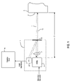
- FIG. 5 is a block diagram of a range sensor according to at least one alternate embodiment.
- FIG. 1 is a block diagram of a ranger sensor 1 according to at least some exemplary embodiments of the invention.
- sensor 1 measures a distance D to a target surface 2 of an arbitrary target object 3 .
- Sensor 1 includes a vertical cavity surface emitting laser (VCSEL) 5 , a photosensitive detector (PD) 6 , a lens 7 and a partially reflective surface 8 .
- VCSEL 5 receives power in the form of a biasing current.
- Laser light emanating from the emitting cavity of VCSEL 5 passes through lens 7 and surface 8 to exit sensor 1 as outgoing light beam 10 .
- a backscattered portion of beam 10 (shown as broken line arrow 11 ) is returned into the emitting cavity of VCSEL 5 , as discussed more fully below.
- Surface 8 is partially reflective, and thus directs a small portion of the beam 10 (approximately 5%) to PD 6 .
- the output of PD 6 varies based on the intensity of light reflected from surface 8 . Accordingly, output of PD 6 can also be used to measure the output of beam 10 .
- PD 6 can be a photodiode, a phototransistor or other type of device which varies its output based on the intensity of received light. Fluctuations in the output from PD 6 are measured by detection circuitry 15 and used to determine the distance D. Detection circuitry 15 is described in more detail below in conjunction with FIG. 4 .
- Backscattered light 11 from target surface 2 that enters the emitting cavity of VCSEL 5 mixes with the light being newly generated. Because of the self-mixing effect, the power output by VCSEL 5 in outgoing light beam 10 is thereby affected. Self-mixing per se is known in the art, and thus a detailed description of the phenomenon is not included herein. In general, however, the power of beam 10 will fluctuate (or “beat”) in a periodic manner as a result of interference between the outgoing light being generated in the VCSEL emitting cavity and the backscattered light from a target.
- FIG. 1 shows outgoing light beam 10 and backscattered light 11 as separate arrows, this is only to simplify the drawing. In theory, backscattered light from a target mixes with the outgoing light beam to form a waveform that includes a beat.
- the periodic fluctuation of the output beam power corresponds to mode hops in VCSEL 5 occurring at target displacements in multiples of ⁇ /2, where ⁇ is the wavelength of VCSEL 5 .
- the wavelength of VCSEL 5 is periodically changed by modulating the bias current with a triangular wave function, so that phase shifts of 2 ⁇ occur at every resonant mode created by the laser and the target.
- the output wavelength of a VCSEL will increase as the bias current for that VCSEL increases.
- the frequency of beam 10 will fall during the upslope of the modulating wave and will rise during the downslope of that modulating wave.
- the distance D can then be determined by finding the frequency spacing between the adjacent modes.
- the distance D from VCSEL 5 to target surface 2 (i.e., the external cavity length for VCSEL 5 ) can be determined from Equation 1.
- Equation 1 c is the speed of light (m/sec).
- the frequency modulation coefficient ⁇ expressed in GHz/mA, provides the frequency of beam 10 for a given bias current over the operating range of VCSEL 5 .
- the coefficient m is the slope of the triangular bias current modulating wave, expressed in mA/sec.
- the quantity p avg is the average period (e.g., time between peaks) of the beat signal. Because p avg is equal to the inverse of the average frequency (f avg ) of the beat signal, distance D can alternatively be determined from Equation 2.
- FIG. 2 shows examples of a beat signal wave and a corresponding modulating wave for one type of single-mode VCSEL.
- the output frequency of the VCSEL varies by +/ ⁇ 29 GHz; the modulating wave frequency (f m ) is 1.3 KHz, and the external cavity length (D) is 100 mm.
- Equations 1 and 2 are relatively straightforward, various factors can hinder an accurate determination of the distance D. Some of these factors are described by reference to FIGS. 3A and 3B .
- FIGS. 3A and 3B shows, in a simplified form and on the same time scale, an example of a beat signal waveform and the modulating bias current used to create that beat signal.
- FIG. 3A there is an abrupt phase reversal in the beat signal waveform at the inflection of the modulating wave (i.e., where the triangle wave goes from rising to falling).
- a similar phase reversal occurs at each inflection of the bias current modulation wave (including each falling-to-rising inflection).
- phase reversals can increase measurement errors when determining f avg or p avg .
- One example of potential inaccuracy is seen by comparing sampling windows A and B.
- Windows A and B are of equal duration, but located on different portions of the beat signal wave.
- Window A is located on a portion of the beat signal wave which does not include a phase reversal, and contains 5 peaks.
- Window B is located on a portion of the beat signal wave that does include a phase reversal. Because the phase reversal occurs near a peak of the beat signal waveform, however, the portions of the beat signal waveform on either side of the phase reversal are treated as a single peak.
- the beat signal is closer to its trough at the time of phase reversal. This results in a count of two peaks at the phase reversal in window C instead of one peak, as in window B of FIG. 3A .
- This unpredictability of beat signal phase at the inflections is caused by several factors.
- One contributing factor is the nonlinearity of the VCSEL itself. Specifically, the change in VCSEL output light frequency in response to bias current change is not truly linear. Yet another contributing factor is the distance being measured. Because the phase of the backscattered light 11 re-entering VCSEL 5 will vary based on that distance D, the phase of the beat signal wave is also affected by that distance.
- the average beat frequency f avg is a function of the number of beat signal waveforms (N Tm ) during a period (T m ) of the modulating wave.
- N Tm increase achieved with a high optical frequency excursion can severely disturb the beat signal envelope. This can make beat frequency detection more difficult. Numerous other factors can also complicate frequency determination.
- the beat signal frequently has a low signal-to-noise ratio (SNR). This low SNR is caused by, e.g., speckling from the target surface. The strength of the backscattered light received by the VCSEL may also be greatly diminished, particularly for longer distances and/or absorptive target surfaces.
- the shape of the beat signal waveform also complicates determination of f avg .
- the beat signal is shown as a regularly-shaped wave for simplicity. In practice, however, beat signal waveforms are not standard sine or square waves. Instead, beat signal waves often have an irregular shape which can be difficult to detect.
- FIG. 4 is a block diagram providing additional details of detection circuitry 15 which, according to at least one exemplary embodiment, addresses the above and other difficulties in determining the beat signal frequency.
- Many of the individual components of detection circuitry 15 e.g., filters, amplifiers, etc.
- filters, amplifiers, etc. represent previously-known components; such components are represented in block form for simplicity.
- Persons skilled in the art will appreciate that various known circuits can be employed for each of the components shown in block diagram form. The selection of such circuits will be apparent to persons skilled in the art in view of the information provided herein, which information shows the combination of such known components in a new manner to achieve a new and advantageous result.
- VCSEL 5 of sensor 1 is driven by a triangularly-modulated bias current from current generator 25 .
- the beat signal output by PD 6 of sensor 1 is initially fed to pre-amplifier 20 . This increases the strength of the relatively low power signal output by PD 6 .
- the output of preamplifier 20 is then fed to triangle wave band eliminator 21 . Because VCSEL 5 of sensor 1 is being driven with a triangle-wave modulated bias current, the beat signal will include a harmonic having the triangular wave frequency. Accordingly, triangle wave eliminator 21 subtracts that triangular wave frequency from the beat signal.
- the output of triangle wave eliminator 21 is then input to band pass filter 22 to remove frequencies outside a predetermined pass range (e.g., 50-500 KHz).
- This range corresponds to expected values for f avg over a range of values for distance D measurable by sensor 1 and detection circuitry 15 .
- the output from band pass filter 22 is then input to a difference frequency analog phase locked loop (DFAPLL) 28 for additional noise reduction.
- DFAPLL difference frequency analog phase locked loop
- analog phased locked loops have good noise rejection and amplitude modulation rejection qualities, they can be used to regenerate a less-noisy version of a noisy input signal.
- an analog PLL can be used to enhance the accuracy with which beat signal frequency (and thus, distance) is measured.
- typical analog PLLs have a limited “lock” range of approximately ⁇ 20% of the center frequency of the voltage controlled oscillator (VCO) in the PLL. In other words, such a PLL would only be able to reproduce input frequencies that are within 20% of the VCO center frequency. If such an analog PLL were used in detection circuitry 15 , the system would be limited to measuring displacements within 20% of some reference displacement value. If for example, a conventional analog PLL was selected based on a reference displacement of 1 m, the system would only be able to measure values of D between 0.8 m and 1.2 m.
- a VCO of a DFAPLL has a center frequency which is substantially higher (e.g., an order of magnitude or more) than the highest expected beat signal frequency, but which also has a frequency response which is sufficiently wide.
- a frequency downconverter is then used to subtract a reference frequency from the VCO output. Because the lock-in range of a DFAPLL can be quite large (e.g., 2 KHZ ⁇ 1 MHZ), a DFAPLL can be used to expand the range of distances which can be measured.
- DFAPLL 28 of detection circuitry 15 includes a phase detector 29 , a loop filter 30 , a VCO 31 , a reference frequency oscillator 32 and a frequency mixer 33 .
- the signal from photosensitive detector 6 after pre-conditioning by pre-amplifier 20 , modulation eliminator 21 and band pass filter 22 , is input to phase detector 29 .
- Phase detector 29 measures the difference in phase between the beat signal frequency and the output from frequency mixer 33 , which is discussed below.
- a phase difference signal output from phase detector 29 is then filtered by loop filter 30 and fed to VCO 31 . Similar to other PLLs, VCO 31 then adjusts its output frequency based on the phase difference signal.
- VCO 31 decreases its output frequency. If the beat signal frequency is higher than the other frequency input to phase detector 29 , VCO 31 increases its output frequency.
- the output of VCO 31 is fed to mixer 33 .
- a reference frequency generated by reference frequency oscillator 32 is also fed to mixer 33 .
- the frequency of the signal output by VCO 31 is reduced (or “downconverted”) by the reference frequency from oscillator 32 .
- the downconverted output from mixer 33 (the difference frequency output signal) is then fed to phase detector 29 .
- phase detector 29 compares the beat signal with the difference frequency output signal from mixer 33 to generate the phase difference signal. Because VCO 31 continually adjusts its output so as to reduce the phase difference signal, and because the VCO output is frequency downconverted in mixer 33 so as to be within the range of the beat signal frequency, the difference frequency output signal from mixer 33 will match the beat signal frequency once DFAPLL 28 reaches equilibrium.
- the difference frequency output signal from mixer 33 is a purified form of the signal received from band pass filter 22 . In particular, processing by DFAPLL 28 removes noise and other anomalies in the beat signal previously described.
- the following example further illustrates the operation of DFAPLL 28 .
- the beat signal frequency will, for the range of velocities to be measured, vary between 50 KHz and 500 KHz.
- An analog PLL without a frequency downconversion stage would be unable to reproduce frequencies over that entire range.
- a VCO with a center frequency of 275 KHz halfway between 50 KHz and 500 KHz
- VCO 31 has a 10 MHz center frequency, however, it would be able to output a sufficiently wide range of frequencies.
- VCO Even if such a VCO has a dynamic range of only 5%, it could output frequencies from approximately 9.5 MHz to approximately 10.5 MHz, a spread of approximately 1000 KHz. Because the output of that VCO would always be higher than the beat signal frequency, however, the VCO output is reduced by a reference frequency (from oscillator 32 ) of 9.5 MHz. If the beat signal input to phase detector 29 has a frequency of 50 kHz, VCO 31 will (after DFAPLL 28 reaches equilibrium) output a 9.55 MHz signal. After downconversion by the 9.5 MHz reference frequency, a 0.05 MHz (50 KHz) difference frequency output signal is output by mixer 33 and DFAPLL 28 .
- phase detector 29 Similarly, a 500 KHz beat signal input to phase detector 29 would cause VCO 31 to ultimately output a 10 MHz signal. After downconversion by the 9.5 MHz reference frequency, a 0.50 MHz (500 KHz) difference frequency output signal is output by mixer 33 and DFAPLL 28 .
- the difference frequency output signal from DFAPLL 28 is provided to frequency counter 35 .
- Frequency counter 35 determines the beat signal frequency f avg and outputs a value of f avg to distance calculator 36 .
- Distance calculator 36 (which may be, e.g., a microprocessor or other logic circuitry) then determines the distance D based on Equation 2.
- detection circuitry 15 (including distance calculator 36 ) and/or sensor 1 and/or current generator 25 are contained on a signal integrated circuit chip.
- Temperature controller 37 may be, e.g., a thermostatically-controlled thermoelectric device in thermal communication with sensor 1 .
- the response of many VCSELs to bias current modulation is also dependent upon temperature, and maintaining the temperature of sensor 1 at a known level can further increase measurement accuracy. It is to be noted, however, that a temperature controller is not required. Notably, and as discussed below, a prototype of the system shown in FIG. 4 has achieved results without temperature control that are satisfactory for many applications.
- a VCSEL was used in sensor 1 .
- VCSELs offer numerous advantages over other types of laser devices (e.g., circular beam shape, lower threshold current), other types of laser devices could be used.
- an edge emitting laser diode EELD
- sensor 1 of FIG. 1 has been replaced with sensor 1 ′.
- Sensor 1 ′ includes an EELD 5 ′.
- EELD 5 ′ emits from two edges. Accordingly, laser light from one edge of EELD 5 ′ passes through lens 7 ′ and out of sensor 1 ′ as beam 10 ′.
- PD 6 ′ Light emanating from the other edge of EELD 5 ′ strikes PD 6 ′.
- the output of PD 6 ′ is then used, in a manner similar to the output from PD 6 of FIG. 1 , to measure power output of beam 10 ′.
- the signal output from PD 6 ′ is then processed in a manner similar to that previously described for the signal output from PD 6 .
- a prototype of the system shown in FIG. 4 was constructed using a VCSEL having a nominal wavelength of 850 nm that varied with bias current at a rate ( ⁇ / ⁇ I) of 0.25 nm/mA.
- the bias current was modulated with a triangular wave having a frequency f m of 1.3 KHz and a peak-to-peak amplitude of 8 mA +/ ⁇ 0.28 mA, resulting in the values shown in Table 1.
- the DFAPLL phase detector had a gain K d of 1.0V/rad
- the VCO had a gain K O of 1.08 f O /V
- the VCO center frequency f O was 10 MHz
- the reference frequency was 9.5 MHz.
- the input signal to the DFAPLL had an amplitude of 20-300 mV.
- the AM rejection was better than 40 dB.
- the lock-in range of the DFAPLL was 5 KHz to 1 MHz.
- Distances (to a sandblasted metal target) between 50 mm and 500 mm were measured. When laser temperature was maintained between 0° and 55° C., resolution was 1 mm and ranging accuracy was within 4 mm. When laser temperature was maintained at 25+/ ⁇ 2° C., resolution was 1 mm and ranging accuracy was within 2 mm.
- various embodiments provide a self-mixing laser range finder offering improved ranging accuracy and dynamic range, as well as simple configuration and low cost.
- a range sensor can be advantageously utilized in a number of applications.
- various computer input devices can employ a range sensor instead of electrical contacts, potentiometers and other conventional mechanisms for detecting movement of a keyboard key, a slider or other type of control piece. Examples of input devices employing range measurement are described in commonly-owned U.S. patent application Ser. No. 10/953,107, titled “Keyboard or Other Input Device Using Ranging for Detection of Control Piece Movement” and filed Sep. 30, 2004.
- a distance sensor could be employed to determine the distance between a user and a computer display. That distance could then be used to adjust the display contents to accommodate users who may be too far from the screen to, e.g., read normal sized text.
- a distance sensor could be used to track a user's hand as part of an input command (e.g., the user moves his hand away from the computer to zoom in a display). Beyond computer input, an accurate and inexpensive distance sensor has numerous other uses (e.g., in a camera autofocus, in numerous computer vision applications, etc.).
Abstract
Description
| TABLE 1 | ||||
| Δλ | +/−0.07 | nm | ||
| Δf(laser light) | +/−29 | GHz | ||
| m | 1456 | mA/s | ||
| Ω | 104 | GHz/mA | ||
Claims (11)
Priority Applications (1)
| Application Number | Priority Date | Filing Date | Title |
|---|---|---|---|
| US11/249,682 US7283214B2 (en) | 2005-10-14 | 2005-10-14 | Self-mixing laser range sensor |
Applications Claiming Priority (1)
| Application Number | Priority Date | Filing Date | Title |
|---|---|---|---|
| US11/249,682 US7283214B2 (en) | 2005-10-14 | 2005-10-14 | Self-mixing laser range sensor |
Publications (2)
| Publication Number | Publication Date |
|---|---|
| US20070091295A1 US20070091295A1 (en) | 2007-04-26 |
| US7283214B2 true US7283214B2 (en) | 2007-10-16 |
Family
ID=37984986
Family Applications (1)
| Application Number | Title | Priority Date | Filing Date |
|---|---|---|---|
| US11/249,682 Active 2025-10-25 US7283214B2 (en) | 2005-10-14 | 2005-10-14 | Self-mixing laser range sensor |
Country Status (1)
| Country | Link |
|---|---|
| US (1) | US7283214B2 (en) |
Cited By (22)
| Publication number | Priority date | Publication date | Assignee | Title |
|---|---|---|---|---|
| US20060066576A1 (en) * | 2004-09-30 | 2006-03-30 | Microsoft Corporation | Keyboard or other input device using ranging for detection of control piece movement |
| US20060213997A1 (en) * | 2005-03-23 | 2006-09-28 | Microsoft Corporation | Method and apparatus for a cursor control device barcode reader |
| US20070002013A1 (en) * | 2005-06-30 | 2007-01-04 | Microsoft Corporation | Input device using laser self-mixing velocimeter |
| US20070102523A1 (en) * | 2005-11-08 | 2007-05-10 | Microsoft Corporation | Laser velocimetric image scanning |
| US20070109267A1 (en) * | 2005-11-14 | 2007-05-17 | Microsoft Corporation | Speckle-based two-dimensional motion tracking |
| US20070109268A1 (en) * | 2005-11-14 | 2007-05-17 | Microsoft Corporation | Speckle-based two-dimensional motion tracking |
| US20080094134A1 (en) * | 2006-10-24 | 2008-04-24 | Nec Electronics Corporation | Semiconductor integrated circuit device |
| US20080111797A1 (en) * | 2006-11-15 | 2008-05-15 | Yu-Sheop Lee | Touch screen |
| US20100283990A1 (en) * | 2009-05-07 | 2010-11-11 | Dezhong Yang | Optoelectronic distance measuring device |
| WO2010032202A3 (en) * | 2008-09-17 | 2010-11-18 | Philips Intellectual Property & Standards Gmbh | Wavelength-controlled semiconductor laser device |
| US20110116101A1 (en) * | 2008-07-07 | 2011-05-19 | Koninklijke Philips Electronics N.V. | Laser self-mixing measuring device |
| US20110148710A1 (en) * | 2009-12-23 | 2011-06-23 | Itrack, Llc | Distance separation tracking system |
| WO2012049561A1 (en) | 2010-10-15 | 2012-04-19 | Universitat Politècnica De Catalunya | A method of measuring a displacement-related parameter using a laser self-mixing measuring system, and a laser self-mixing measuring system |
| US20120160031A1 (en) * | 2009-06-23 | 2012-06-28 | Imec | Optical tactile sensors |
| DE102011101809A1 (en) * | 2011-05-17 | 2012-11-22 | M3i Technologies GmbH | Slider for electrical or electronic device e.g. mixers used in music industry, has actuators that are removed from their current position relative to light source, on linear adjustment path, to determine their position dependent output |
| US9091538B2 (en) | 2013-02-19 | 2015-07-28 | Chengdu Haicun Ip Technology Llc | Laser landing altimeter for precision aircraft landing aid |
| US9506944B2 (en) | 2010-11-03 | 2016-11-29 | Koninklijke Philips N.V. | Velocity determination apparatus |
| US10191454B2 (en) * | 2016-06-13 | 2019-01-29 | William Marsh Rice University | Methods and related systems of ultra-short pulse detection |
| US11006828B2 (en) | 2014-07-17 | 2021-05-18 | 1 Sonic Medical Corporation, S.A.S. | Measurement of ocular parameters using vibrations induced in the eye |
| RU2750681C1 (en) * | 2020-10-07 | 2021-07-01 | Самсунг Электроникс Ко., Лтд. | Optical sensor device for determining range, speed and identification of shape and structure of object |
| US11112233B2 (en) | 2019-09-12 | 2021-09-07 | Apple Inc. | Self-mixing particulate matter sensors using VCSELs with extrinsic photodiodes |
| US11501224B2 (en) | 2018-01-24 | 2022-11-15 | Andersen Corporation | Project management system with client interaction |
Families Citing this family (16)
| Publication number | Priority date | Publication date | Assignee | Title |
|---|---|---|---|---|
| CN101897089B (en) | 2007-12-11 | 2013-02-06 | 皇家飞利浦电子股份有限公司 | Semiconductor laser with integrated phototransistor |
| US8279415B2 (en) * | 2009-02-13 | 2012-10-02 | Robert Welland | Method and apparatus for distance measurement using optical beam |
| EP2409115A2 (en) * | 2009-03-18 | 2012-01-25 | Koninklijke Philips Electronics N.V. | Apparatus for determining a flow property of a fluid |
| EP2654143A1 (en) * | 2012-04-18 | 2013-10-23 | Nederlandse Organisatie voor toegepast -natuurwetenschappelijk onderzoek TNO | Frequency tunable laser system |
| JP2014059222A (en) * | 2012-09-18 | 2014-04-03 | Denso Corp | Optical radar device |
| US9831630B2 (en) * | 2014-02-06 | 2017-11-28 | GM Global Technology Operations LLC | Low cost small size LiDAR for automotive |
| CN104236464B (en) * | 2014-09-04 | 2017-03-22 | 宁波舜宇智能科技有限公司 | Laser vibration displacement sensor and measuring method thereof |
| JP6018662B2 (en) * | 2015-03-31 | 2016-11-02 | アズビル株式会社 | Counting device, physical quantity sensor, counting method and physical quantity measuring method |
| JP2019502925A (en) * | 2016-01-22 | 2019-01-31 | メズメリズ インク. | Apparatus, method and application for signal detection |
| CN105716704B (en) * | 2016-04-20 | 2019-05-28 | 安徽大学 | The chip-shaped laser of microcavity is from mixing vibration, displacement, velocity pick-up method |
| CN109782298B (en) * | 2016-04-20 | 2020-06-02 | 安徽大学 | Different-side coupling type microcavity chip type laser self-mixing distance sensing system |
| US20190331473A1 (en) * | 2016-06-13 | 2019-10-31 | Vixar, Llc | Improved self-mix module utilizing filters |
| DE102017215783A1 (en) * | 2017-09-07 | 2019-03-07 | Robert Bosch Gmbh | Method for operating a laser rangefinder |
| DE102018215177A1 (en) * | 2018-09-06 | 2020-03-12 | Robert Bosch Gmbh | Autofocus and particle sensor device and corresponding method, as well as camera and particle sensor system |
| IT201900015761A1 (en) * | 2019-09-06 | 2021-03-06 | St Microelectronics Srl | Optical proximity sensor and corresponding operating procedure |
| EP3968475B1 (en) * | 2020-09-15 | 2023-08-23 | TRUMPF Photonic Components GmbH | Laser sensor module for self-mixing interferometry |
Citations (38)
| Publication number | Priority date | Publication date | Assignee | Title |
|---|---|---|---|---|
| US3954335A (en) | 1972-06-19 | 1976-05-04 | Siemens Ag | Method and apparatus for measuring range and speed of an object relative to a datum plane |
| US4240745A (en) | 1974-07-29 | 1980-12-23 | The United States Of America As Represented By The Secretary Of The Air Force | Imagery with constant range lines |
| US4379968A (en) | 1980-12-24 | 1983-04-12 | Burroughs Corp. | Photo-optical keyboard having light attenuating means |
| US4721385A (en) | 1985-02-11 | 1988-01-26 | Raytheon Company | FM-CW laser radar system |
| US5114226A (en) * | 1987-03-20 | 1992-05-19 | Digital Optronics Corporation | 3-Dimensional vision system utilizing coherent optical detection |
| US5125736A (en) * | 1990-11-13 | 1992-06-30 | Harris Corporation | Optical range finder |
| US5274361A (en) | 1991-08-15 | 1993-12-28 | The United States Of America As Represented By The Secretary Of The Navy | Laser optical mouse |
| US5274363A (en) | 1991-02-01 | 1993-12-28 | Ibm | Interactive display system |
| US5475401A (en) | 1993-04-29 | 1995-12-12 | International Business Machines, Inc. | Architecture and method for communication of writing and erasing signals from a remote stylus to a digitizing display |
| US5510604A (en) | 1993-12-13 | 1996-04-23 | At&T Global Information Solutions Company | Method of reading a barcode representing encoded data and disposed on an article and an apparatus therefor |
| US5781297A (en) | 1996-08-23 | 1998-07-14 | M&M Precision Systems Corporation | Mixed frequency and amplitude modulated fiber optic heterodyne interferometer for distance measurement |
| US6015089A (en) | 1996-06-03 | 2000-01-18 | Accu-Sort Systems, Inc. | High speed image acquisition system and method of processing and decoding bar code symbol |
| US6040914A (en) | 1997-06-10 | 2000-03-21 | New Focus, Inc. | Simple, low cost, laser absorption sensor system |
| US6333735B1 (en) | 1999-03-16 | 2001-12-25 | International Business Machines Corporation | Method and apparatus for mouse positioning device based on infrared light sources and detectors |
| US20020117549A1 (en) | 2001-02-26 | 2002-08-29 | Martin Lee | Barcode-readable computer mouse |
| US20020158838A1 (en) | 2001-04-30 | 2002-10-31 | International Business Machines Corporation | Edge touchpad input device |
| US20030006367A1 (en) | 2000-11-06 | 2003-01-09 | Liess Martin Dieter | Optical input device for measuring finger movement |
| US6525677B1 (en) | 2000-08-28 | 2003-02-25 | Motorola, Inc. | Method and apparatus for an optical laser keypad |
| US20030085878A1 (en) | 2001-11-06 | 2003-05-08 | Xiadong Luo | Method and apparatus for determining relative movement in an optical mouse |
| US20030085284A1 (en) | 2000-02-28 | 2003-05-08 | Psc Scanning, Inc. | Multi-format bar code reader |
| US20030128190A1 (en) | 2002-01-10 | 2003-07-10 | International Business Machines Corporation | User input method and apparatus for handheld computers |
| US20030128188A1 (en) | 2002-01-10 | 2003-07-10 | International Business Machines Corporation | System and method implementing non-physical pointers for computer devices |
| US6646723B1 (en) | 2002-05-07 | 2003-11-11 | The United States Of America As Represented By The Administrator Of The National Aeronautics And Space Administration | High precision laser range sensor |
| US20040004128A1 (en) | 1996-09-03 | 2004-01-08 | Hand Held Products, Inc. | Optical reader system comprising digital conversion circuit |
| US6687274B2 (en) | 2002-02-04 | 2004-02-03 | Eastman Kodak Company | Organic vertical cavity phase-locked laser array device |
| US20040075823A1 (en) * | 2002-04-15 | 2004-04-22 | Robert Lewis | Distance measurement device |
| US20040095323A1 (en) | 2002-11-15 | 2004-05-20 | Jung-Hong Ahn | Method for calculating movement value of optical mouse and optical mouse using the same |
| US20040213311A1 (en) | 2000-11-28 | 2004-10-28 | Johnson Ralph H | Single mode vertical cavity surface emitting laser |
| US20040228377A1 (en) | 2002-10-31 | 2004-11-18 | Qing Deng | Wide temperature range vertical cavity surface emitting laser |
| US20040227954A1 (en) | 2003-05-16 | 2004-11-18 | Tong Xie | Interferometer based navigation device |
| US20040246460A1 (en) * | 2001-08-03 | 2004-12-09 | Franz Auracher | Method and device for adjusting a laser |
| US20050068300A1 (en) | 2003-09-26 | 2005-03-31 | Sunplus Technology Co., Ltd. | Method and apparatus for controlling dynamic image capturing rate of an optical mouse |
| US6903662B2 (en) | 2002-09-19 | 2005-06-07 | Ergodex | Computer input device with individually positionable and programmable input members |
| WO2005055037A1 (en) | 2003-12-03 | 2005-06-16 | Chois Technology Co., Ltd. | Optical mouse operable in 3-dimensional space |
| US20050156875A1 (en) | 2004-01-21 | 2005-07-21 | Microsoft Corporation | Data input device and method for detecting lift-off from a tracking surface by laser doppler self-mixing effects |
| US20050157202A1 (en) | 2004-01-16 | 2005-07-21 | Chun-Huang Lin | Optical mouse and image capture chip thereof |
| US20050179658A1 (en) | 2004-02-18 | 2005-08-18 | Benq Corporation | Mouse with a built-in laser pointer |
| US20050231484A1 (en) | 1995-10-06 | 2005-10-20 | Agilent Technologies, Inc. | Optical mouse with uniform level detection method |
-
2005
- 2005-10-14 US US11/249,682 patent/US7283214B2/en active Active
Patent Citations (39)
| Publication number | Priority date | Publication date | Assignee | Title |
|---|---|---|---|---|
| US3954335A (en) | 1972-06-19 | 1976-05-04 | Siemens Ag | Method and apparatus for measuring range and speed of an object relative to a datum plane |
| US4240745A (en) | 1974-07-29 | 1980-12-23 | The United States Of America As Represented By The Secretary Of The Air Force | Imagery with constant range lines |
| US4379968A (en) | 1980-12-24 | 1983-04-12 | Burroughs Corp. | Photo-optical keyboard having light attenuating means |
| US4721385A (en) | 1985-02-11 | 1988-01-26 | Raytheon Company | FM-CW laser radar system |
| US5114226A (en) * | 1987-03-20 | 1992-05-19 | Digital Optronics Corporation | 3-Dimensional vision system utilizing coherent optical detection |
| US5125736A (en) * | 1990-11-13 | 1992-06-30 | Harris Corporation | Optical range finder |
| US5274363A (en) | 1991-02-01 | 1993-12-28 | Ibm | Interactive display system |
| US5274361A (en) | 1991-08-15 | 1993-12-28 | The United States Of America As Represented By The Secretary Of The Navy | Laser optical mouse |
| US5475401A (en) | 1993-04-29 | 1995-12-12 | International Business Machines, Inc. | Architecture and method for communication of writing and erasing signals from a remote stylus to a digitizing display |
| US5510604A (en) | 1993-12-13 | 1996-04-23 | At&T Global Information Solutions Company | Method of reading a barcode representing encoded data and disposed on an article and an apparatus therefor |
| US20050231484A1 (en) | 1995-10-06 | 2005-10-20 | Agilent Technologies, Inc. | Optical mouse with uniform level detection method |
| US6015089A (en) | 1996-06-03 | 2000-01-18 | Accu-Sort Systems, Inc. | High speed image acquisition system and method of processing and decoding bar code symbol |
| US5781297A (en) | 1996-08-23 | 1998-07-14 | M&M Precision Systems Corporation | Mixed frequency and amplitude modulated fiber optic heterodyne interferometer for distance measurement |
| US20040004128A1 (en) | 1996-09-03 | 2004-01-08 | Hand Held Products, Inc. | Optical reader system comprising digital conversion circuit |
| US6040914A (en) | 1997-06-10 | 2000-03-21 | New Focus, Inc. | Simple, low cost, laser absorption sensor system |
| US6333735B1 (en) | 1999-03-16 | 2001-12-25 | International Business Machines Corporation | Method and apparatus for mouse positioning device based on infrared light sources and detectors |
| US20030085284A1 (en) | 2000-02-28 | 2003-05-08 | Psc Scanning, Inc. | Multi-format bar code reader |
| US6525677B1 (en) | 2000-08-28 | 2003-02-25 | Motorola, Inc. | Method and apparatus for an optical laser keypad |
| US6872931B2 (en) | 2000-11-06 | 2005-03-29 | Koninklijke Philips Electronics N.V. | Optical input device for measuring finger movement |
| US20030006367A1 (en) | 2000-11-06 | 2003-01-09 | Liess Martin Dieter | Optical input device for measuring finger movement |
| US20040213311A1 (en) | 2000-11-28 | 2004-10-28 | Johnson Ralph H | Single mode vertical cavity surface emitting laser |
| US20020117549A1 (en) | 2001-02-26 | 2002-08-29 | Martin Lee | Barcode-readable computer mouse |
| US20020158838A1 (en) | 2001-04-30 | 2002-10-31 | International Business Machines Corporation | Edge touchpad input device |
| US20040246460A1 (en) * | 2001-08-03 | 2004-12-09 | Franz Auracher | Method and device for adjusting a laser |
| US20030085878A1 (en) | 2001-11-06 | 2003-05-08 | Xiadong Luo | Method and apparatus for determining relative movement in an optical mouse |
| US20030128190A1 (en) | 2002-01-10 | 2003-07-10 | International Business Machines Corporation | User input method and apparatus for handheld computers |
| US20030128188A1 (en) | 2002-01-10 | 2003-07-10 | International Business Machines Corporation | System and method implementing non-physical pointers for computer devices |
| US6687274B2 (en) | 2002-02-04 | 2004-02-03 | Eastman Kodak Company | Organic vertical cavity phase-locked laser array device |
| US20040075823A1 (en) * | 2002-04-15 | 2004-04-22 | Robert Lewis | Distance measurement device |
| US6646723B1 (en) | 2002-05-07 | 2003-11-11 | The United States Of America As Represented By The Administrator Of The National Aeronautics And Space Administration | High precision laser range sensor |
| US6903662B2 (en) | 2002-09-19 | 2005-06-07 | Ergodex | Computer input device with individually positionable and programmable input members |
| US20040228377A1 (en) | 2002-10-31 | 2004-11-18 | Qing Deng | Wide temperature range vertical cavity surface emitting laser |
| US20040095323A1 (en) | 2002-11-15 | 2004-05-20 | Jung-Hong Ahn | Method for calculating movement value of optical mouse and optical mouse using the same |
| US20040227954A1 (en) | 2003-05-16 | 2004-11-18 | Tong Xie | Interferometer based navigation device |
| US20050068300A1 (en) | 2003-09-26 | 2005-03-31 | Sunplus Technology Co., Ltd. | Method and apparatus for controlling dynamic image capturing rate of an optical mouse |
| WO2005055037A1 (en) | 2003-12-03 | 2005-06-16 | Chois Technology Co., Ltd. | Optical mouse operable in 3-dimensional space |
| US20050157202A1 (en) | 2004-01-16 | 2005-07-21 | Chun-Huang Lin | Optical mouse and image capture chip thereof |
| US20050156875A1 (en) | 2004-01-21 | 2005-07-21 | Microsoft Corporation | Data input device and method for detecting lift-off from a tracking surface by laser doppler self-mixing effects |
| US20050179658A1 (en) | 2004-02-18 | 2005-08-18 | Benq Corporation | Mouse with a built-in laser pointer |
Non-Patent Citations (99)
| Title |
|---|
| "Laser Sensors Offer Long Stand-off and Measurement Range", ThomasNet Industrial news Room, <http://www.news.thomasnet.com/fullstory/458005/1782>, date of first publication unknown, but dated Dec. 3, 2004, 5 pages. |
| "Laser-Based Tracking for Real-Time 3D Gesture Acquistion", <http://www.k2.t.u-tokyo.ac.jp/fusion/LaserActive Tracking/index-e.html>; first published on or before Aug. 3, 2004. |
| "Optical Mouse Saves Space", <http://www.optics.org/articles/news/8/6/23/1>, date of first publication unknown, but believed to be Jun. 26, 2002. |
| "Ultra-miniature Laser Displacement Sensors", <http://www.globalspec.com/FeaturedProducts/Detail/BaumerElectric/Ultraminiature<SUB>-</SUB>Laser<SUB>-</SUB>Displacement<SUB>-</SUB>Sensors/13470/1>, first date of publication unknown, but prior to Sep. 12, 2005, 2 pages. |
| 5-button USB Laser Mouse; <http://www.logear.com/main.php?loc=product&item=GME521>; date of first publication unknown, but on or before Oct. 24, 2005; 3 pages. |
| Acket, G., et al., "The Influence of Feedback Intensity on Longitudinal Mode Properties and Optical Noise in Index-Guided Semiconductor Lasers", IEEE Journal of Quantum Electronics, vol. QE-20, No. 10, pp. 1163-1169, Oct. 1984. |
| Acroname Articles, Demystifying the Sharp IR Rangers, <http://www.acroname.com/rootics/info/articles/sharp/sharp.html> (First published before Sep. 14, 2004). |
| Aeroflex Mixed-Signal Asics, "Choosing an Ultrasonic Sensor for Proximity or Distance Measurement", Part 1: Acoustic Considerations <http://www.sensorsmag.com/articles/0299/acou0299/main.shtml>; first published in 1999. |
| Besesty, Pascal, et al., "Compact FMCW Advanced Laser Range Finder", pp. 552-553, (1999) Technical Digest Conference on Lasers and Electro-Optics. |
| Besnard, Pascal, et al., "Feedback Phenomena in a Semiconductor Laser Induced by Distant Reflectors", IEEE Journal of Quantum Electronics, pp. 1271-1284, (May 1993) vol. 29, No. 5. |
| Besnard, Pascal, et al., "Microwave Spectra in External-Cavity Semiconductor Lasers: Theoretical Modeling of Multipass Resonances", IEEE Journal of Quantum Electronics, pp. 1713-1722, (Aug. 1994) vol. 30, No. 8. |
| Bezin, G., et al., "A New Laser Range-Finder Based on FMCW-Like Method", IEEE Instrumentation and Measurement Technology Conference, (1996), pp. 90-93. |
| Bosch, T. et al., "A Low-cost, Optical Feedback Laser Range-Finder with Chirp Control", (2001), IEEE Instrumentation and Measurement Technology Conference. |
| Bosch, Thierry, et al., "Three-Dimensional Object Construction Using a Self-Mixing Type Scanning Laser Range Finder", pp. 1326-1329. (1998), IEEE Transactions on Instrumentation and Measurement, vol. 47, No. 5. |
| Canesta, Inc., "Data Input Alternatives for Mobile Devices", pp. 1-5, Nov. 28, 2002. |
| Cole, Timothy, et al., "Fight Characterization of the Near Laser Rangefinder", pp. 131-142, (2000), Laser Radar Technology and Applications, Proceedings of SPIE vol. 4035. |
| D. Dupuy, et al., "Improvement of the FMCW Laser Range-Finder by an APD Working as an Optoelectronic Mixer," IEEE Transactions on Instrumentation and Measurement, 51, 5, pp. 1010-1014, 2002. |
| Dandliker, R., et al., "Two-Wavelength Laser Interferometry Using Superheterodyne Detection", pp. 339-341, Optics Letters, (1998) vol. 13, No. 5. |
| De Groot, Peter, et al., "Chirped Synthetic-Wavelength Interferometry", pp. 1626-1628, (1992), Optics Letters, vol. 17, No. 22. |
| Dorsch, Rainer G., et al., "Laser Triangulation: Fundamental Uncertainty in Distance Measurement", pp. 1306-1314, (1994), Applied Optics, vol. 33, No. 7. |
| Dupuy, D., et al., "A FMCW Laser Range-Finder Based on a Delay Line Technique", pp. 1084-1088, (2001), IEEE Instrumentation and Measurement Technology Conference. |
| E.T. Shimizu, "Directional Discrimination in the Self-Mixing Type Laser Doppler Velocimeter", Appl. Opt., vol. 25, No. 21, pp. 4541-4544, Nov. 1987. |
| F. Robert, et al., "Polarization Modulation Dynamics of Vertical-Cavity Surface-Emitting Lasers with an Extended Cavity", IEEE Journal of Quantum Electronics, vol. 33, No. 12, 2231-2239, Dec. 1997. |
| Favre-Bulle, Bernard, et al., "Efficient Tracking of 3D-Robot Positions by Dynamic Triangulation", pp. 446-449 (1998), IEEE ITMC Session on Instrumentation and Measurement in Robotics. |
| Gagnon, Eric, "Laser Range Imaging Using the Self-Mxing Effect in a Laser Diode", pp. 693-699, (1999), IEEE Transactions on Instrumentation and Measurement, vol. 48, No. 3. |
| Gelmini, E, et al., "Tunable Double-Wavelength Heterodyne Detection Interferometer for Absolute-Distance Measurements", pp. 213-215, (1994), Optics Letters, vol. 19, No. 3. |
| Guido Giuliani, et al., "Laser Diode Self-Mixing Technique for Sensing Applications", J. Opt. A: Pure Appl. Opt, 4, vol. 4, No. 6, pp. S283-S294, Nov. 4, 2002. |
| H. Yeh, et al., "Localized Fluid Flow Measurements with an He-Ne Laser Spectrometer", Appl. Phys. Lett., vol. 4, No. 10, pp. 176-178, May 15, 1984. |
| H.W. Jentink, et al., "Small Laser Doppler Velocimeter Based on the Self-Mixing Effect in a Diode Laser", Appl. Opt. vol. 27, No. 2, pp. 379-385, Jan. 15, 1998. |
| Hebert, Martial, "Active and Passive Range Sensing for Robotics", pp. 102-110, (2000) IEEE International Conference for Robotics and Automation. |
| Hewett, Jacqueline, "Holey VCSELs Produce High Powers", <http://www.optics.org/articles/news/10/12/5/1>, date of first publication unknown, but dated Dec. 2004; 2 pages. |
| Houghton, Andrew, et al., "A Method for Processing Laser Speckle Images to Extract High-Resolution Motion" pp. 611-617, Meas. Sci. Technol. 8 (1997), published Feb. 24, 1997. |
| IBM Technical Disclosure Bulletin, "Ultrasonic Cursor Position Detection", pp. 6712-6714, (1985), vol. 27, No. 11. |
| J. Danckaert, et al., "Minimal Rate Equations Describing Polarization Switching in Vertical-Cavity Surface-Emitting Lasers", Optics Communications, vol. 201, pp. 129-137, Jan. 2002. |
| J. Martin-Regalado, et al., "Polarization Properties of Vertical-Cavity Surface-Emitting Lasers", IEEE Journal of Quantum Electronics, vol. 33, No. 5, pp. 765-783, May 1997. |
| James H. Chumside, "Laser Doppler Velocimetry by Modulating a CO<SUB>2 </SUB>Laser with Backscattered Light", Appl. Opt., vol. 23, No. 1, pp. 61-66, Jan. 1984. |
| Journal, B, et al., "A Low-Cost Laser Range Finder Based on an FMCW-Like Method", pp. 840-843 (2000), IEEE Transactions on Instrumentation and Measurement, vol. 49, No. 4. |
| Journal, B., et al., "High Resolution Laser Range-Finder Based on Phase-Shift Measurement Method", pp. 123-132, (1998), SPIE vol. 3520. |
| K. Petermann, et al., "External Optical Feedback Phenomena in Semiconductor Lasers", IEEE Journal of Selected Topics in Quantum Electronics, vol. 1, No. 2, pp. 480-489, Jun. 1995. |
| L. Fabiny, et al., "Interferometric Fiber-Optic Doppler Velocimeter with High-Dynamic Range", IEEE Photonics Toch. Lett., vol. 9, No. 1, pp. 79-81, Jan. 1997. |
| Logitech(R) G7 Laser Cordless Mouse; <http://www.logitech.com/index.cfm/products/details/US/EN, CRID=2135,CONTENTID=10716>; date of first publication unknown, but on or before Oct. 24, 2005; 3 pages. |
| Logitech(R) MX(TM) 1000 Laser Cordless Mouse; <http://www.logitech.com/index.cfm/products/details/US/EN,CRID=3,CONTENTID=9043,a d=g03&srch=1>; date of first publication unknown, but on or before Oct. 24, 2005; 3 pages. |
| Lowery, James, et al., "Design and Stimulation of a Simple Laser Rangefinder Using a Semiconductor Optical Amplifier-Detector", Optics Express, vol. 13, No. 10, May 16, 2005; pp. 3647-3652. |
| M. Nagahara, et al., "Real-Time Blood Velocity Measurement in Human Retinal Vein Using the Laser Speckle Phenomenon", Japanese Journal of Ophthalmology, 43, pp. 186-195, 1999. |
| M.H. Koelink, et al., "Laser Doppler Velocimeter Based on the Self-Mixing Effect in a Fiber-Coupled Semiconductor Laser: Theory", Appl. Opt., vol. 31, No. 18, pp. 3401-3408, Jun. 20, 1992. |
| M.J. Rudd, "A Laser Doppler Velocimeter Employing the Laser as a Mixer-Oscillator", J. Phys. E1, Series 2, vol. 1, pp. 723-726, Feb. 21, 1968. |
| M.J. Rudd, "A New Theoretical Model for the Laser Dopplemeter", J. Phys. E2, pp. 56-58, 1969. |
| M.K. Mazumber, et al., "Laser Doppler Velocity Measurement Without Directional Ambiguity By Using Frequency Shifted Incident Beams", Appl. Phys. Lett., vol. 16, No. 1, pp. 462-464, Jun. 1, 1970. |
| Maler, T., et al., "A Compact Sensor for Interferometric Displacement Measurements", <http://www.fke.tuwien.ac.at/Publications/jb/fdjb99/tm.htm>, first date of publication unknown, but dated 1999, 2 pages. |
| Marques, Lino, et al., "3D Laser-Based Sensor for Robotics", pp. 1328-1331, (1994) ISR-Institute of Systems and Robotics. |
| Marques, Lino, et al., "A New 3D Optical Triangulation Sensor for Robotics", pp. 512-517, (1998), IEEE International Workshop on Advanced Motion Control. |
| N. Tsukuda, et al., "New Range-Finding Speedometer Using a Self-Mixing Laser Diode Modulated by Triangular Wave Pulse Current", IEEE, WEAM 4-1, pp. 332-335, May 1994. |
| Nerin, P., et al., "Absolute Distance and Velocity Measurement by the FMCW Technique and Self-Mixing Interference Effect Inside a Single-Mode Nd:YAG-LiTAO<SUB>3 </SUB>Microchip Laser", Journal of Optics, vol. 29, No. 3, Jun. 1998. |
| Nyland, Lars S., et al., "Capturing, Processing and Rendering Real-World Scenes", IEEE 2001. |
| Onodera, Ribun, et al., "Effect of Laser-Diode Power Change on Optical heterodyne Interferometry", pp. 675-681, (1995), Journal of Lightwave Technology, vol. 13, No. 4. |
| P.A. Porta, "Laser Doppler Velocimetry by Optical Self-Mixing in Vertical-Cavity Surface-Emitting Lasers", IEEE Photonics Technology Letters, vol. 14, No. 12, pp. 1719-1721, Dec. 2002. |
| P.J. de Groot, et al., "Ranging and Velocimetry Signal Generation in a Backscatter-Modulated Laser Diode", Appl. Opt., vol. 27, No. 21, pp. 4475-4480, Nov. 1988. |
| Peng, Gang, et al., "Design of 3-D Mouse Using Ultrasonic Distance Measurement", International Conference on Sensors and Control Techniques, pp. 226-229; (2000), Proceedings of SPEI, vol. 4077. |
| Poujouty, Stephane, et al., Digital Laser Ranger Finder: Phase-Shift Estimation by Undersampling Technique, pp. 1312-1317, (1999), IEEE. |
| Preucil, Libor, "Building a 2D Environmental Map From Laser Range-Finder date", pp. 290-295, (2000), IEEE Intelligent Vehicle Symposium. |
| R.P. Griffiths, et al., "Cavity-resonant Optical Position Sensor-A New Type of Optical Position Sensor," p. 328, CLEO, 1998. |
| Richard C. Addy, et al., "Effects of External Reflector Alignment in Sensing Applications of Optical Feedback in Laser Diodes", IEEE Journal of Lightwave Technology, December, vol. 14, No. 12, pp. 2672-2676, Dec. 1996. |
| Roland E. Best, "Phase-Locked Loops, Theory, Design, and Applications", McGraw-Hill Book Company, pp. 151-164, 1984 (15 pages). |
| Rornbach, Pirmin, et al., "A Low-Voltage Silicon Condenser Microphone for Hearing Instrument Applications, Microtronic A/S"; date of first publication unknown, but believed to be prior to Sep. 30, 2003. |
| Roy Lang, et al., "External Optical Feedback Effects on Semiconductor Injection Laser Properties", IEEE Journal of Quantum Electronics, vol. QE-16, No. 3, pp. 347-355, Mar. 3, 1980. |
| S. Donati, et al., "Laser Diode Feedback Interferometer for Measurement of Displacements Without Ambiguity", IEEE Journal of Quantum Electronics, vol. 31, No. 1, pp. 113-119, Jan. 1995. |
| S. Kato, et al., "Optical Fibre Laser Doppler Velocimetry Based on Laser Diode Frequency Modulation", Optical and Laser Technology, vol. 27, No. 4, pp. xii, 1995. |
| S. Shinohara, et al., "Acquisition of 3-D Image of Still or Moving Objects Utilizing Laser Diode Range-Finding Speedometer", IEEE, pp. 1730-1735, 1993. |
| S. Shinohara, et al., "Compact and Versatile Self-Mixing Type Semiconductor Laser Doppler Velocimeters with Direction-Discrimination Circuit", IEEE Transactions on Instrumentation and Measurement, vol. 38, No. 2, pp. 574-577, Apr. 1989. |
| S. Shinohara, et al., "Detection of Mesa Spots and Indents on Slowly Moving Object Surface by Laser-Light Beam Scanning", SICE, 105C-5, pp. 1167-1170, Jul. 26-28, 1995. |
| S. Shinohara, et al., "Laser Doppler Velocimeter Using the Self-Mixing Effect of a Semiconductor Laser Diode", Appl. Opl., vol. 25, No. 9, pp. 1417-1419, 1988. |
| S.F. Yu, "Theoretical Analysis of Polarization Bistability in Vertical Cavity Surface Emitting Semiconductor Lasers", IEEE Journal of Lightwave Technology, vol. 15, No. 6, pp. 1032-1041, Jun. 1997. |
| S.K. Ozdemir, et al., "Effect of Linewidth Enhancement Factor on Doppler Beat Waveform Obtained From a Self-Mixing Laser Diode", Optical Review, vol. 7, No. 6, pp. 550-554, Jun. 22, 2000. |
| S.K. Ozdemir, et al., "New Speckle Velocimeter Using Two Self-Mixing Laser Diodes", SICE 115C-3, pp. 947-950, Jul. 29-31, 1997. |
| S.L. Toh, et al., "Whole Field Surface Roughness Measurement by Laser Spackle Correlation Technique", Optics and Laser Technology, 33, pp. 427-434, Jun. 5, 2001. |
| S.W. James, et al., "Fiber Optic Based Reference Beam Laser Doppler Velocimetry", Optics Communications, 119, pp. 460-464, Sep. 15, 1995. |
| Shigenobu Shinohara, et al., "Compact and High-Precision Range Finder with Wide Dynamic Range and its Application", IEEE Transactions on Instrumentation and Measurement, vol. 41, No. 1, pp. 40-44, Feb. 1992. |
| Shinoda, Yukitaka, et al., "Real-Time Computation of Distance and Displacement by Software Instruments Using Optical Frequency Modulation", pp. 82-83, (2002), SICE. |
| Shinohara, Shigenobu, et al., "High-Resolution Range Finder with Wide Dynamic Range of 0.2m to 1m using a Frequency-Modulated Laser Diode", pp. 646-651, (1989), IEEE. |
| Short Talk: Fitt's Law & Text Input, New Horizons, "Interface with Pre-Typing Visual Feedback for Touch Sensitive Keyboard", pp. 750-751, CHI 2003. |
| Steinmetz, Robert, et al., "Solving the Data Input Problem in Mobile Devices", pp. 1-6, Sep. 2002. |
| T. Bosch, et al., "The Self-Mixing Interference Inside a Laser Diode: Application to Displacement, Velocity and Distance Measurement", Proc. SPIE, vol. 3478, pp. 98-108, Jul. 1998. |
| T. Ito, et al., "Integrated Microlaser Doppler Velocimeter", J. Lightwave Tech., vol. 17, No. 1, pp. 30-34, Jan. 1999. |
| T. Shibata, et al., "Laser Speckly Velocimeter Using Self-Mixing Laser Diode", IEEE Transactions on Instrumentation and Measurement, vol. 45, No. 2, pp. 499-503, Apr. 2, 1998. |
| Taka, Nobukatsu, et al., Displacement Measurement of Speckles Using a 2-D Level-cross Technique, Applied Optics, vol. 22, No. 22, published Nov. 15, 1983; pp. 3514-3519. |
| Tomasi, Carlo, et al., "Full Size Projection Keyboard for Handheld Devices", pp. 70-75, (2003) Communications of the ACM, vol. 46, No. 7. |
| Tucker, J.R., et al., "Laser Range Finding Using the Self-Mixing Effect in a Vertical-Cavity Surface Emitting Laser", pp. 583-586, (2002), Conference on Optoelectronic and Microelectronic Materials and Devices. |
| Tucker, John, "Laser Range Finder Using the Self-Mixing Effect in a Vertical Cavity Surface Emitting Laser" (VCSEL), pp. 1-71, (2001). |
| Viarani, Luigi, et al., "A CMOS Smart Pixel for Active 3-D Vision Applications", pp. 145-152, (2004), IEEE Sensors Journal, vol. 4, No. 1. |
| W.H. Stevenson, "Optical Frequency Shifting by means of a Rotating diffraction Grating", Appl. Opt. 9, vol. 9, No. 3, pp. 649-652, Mar. 1970. |
| W.M. Wang, et al., "Self-Mixing Interference in a Diode Laser: Experimental Observations and Theoretical Analysis", Appl. Opt. vol. 32, No. 9, pp. 1551-1558, Mar. 20, 1993. |
| Wakitana, Jun, et al., "Wrist-Mounted Laser Rangefinder", pp. 362-367, (1995) Proceedings of the International Conference on Intelligent Robots and Systems. |
| Whetstone, Albert, "Free-Hand Data Input", pp. 11-28, Science Accessories Corporation (1970). |
| Wu, Qingguang, et al., "New Vibrometer Using Self-Mixing Laser Diode Modulated with Triangular Current", Shizuoka University, Cleo/Pacific Rim/, pp. 290-291 (1997). |
| Y. Kakiuchi, et al., "Measurement of Small Vibrational Displacement by SM LD Vibrometer with Resonance Element", SICE, 107 A-4, pp. 903-908, Jul. 29-31, 1998. |
| Yamaguchi, Ichirou, et al., "Stabilized and Accelerated Speckle Strain Gauge", SPIE Conference on Laser Interferometry; Quantitative Analysis of Interferograms: Third in a Series, Aug. 1989; published Sep. 22, 1991; 8 pages. |
| Zahid, M., et al., "High-Frequency Phase Measurement for Optical Rangefinding System", pp. 141-148, (1997), IEEE Proceedings Science and Measurement Technology, vol. 144, No. 3. |
| Zheng, Jiang A., "A Flexible Laser Range Sensor Based on Spatial-Temporal Analysis", (2000), Proceedings of the International Conference on Pattern Recognition. |
| Zou, Q., et al. "Silicon Capacitive Microphones with Corrugated Diaphragms", School of Mechanical and Production Engineering, Nanyang Technological University; date of first publication unknown, but believed to be prior to Sep. 30, 2003. |
Cited By (34)
| Publication number | Priority date | Publication date | Assignee | Title |
|---|---|---|---|---|
| US7528824B2 (en) | 2004-09-30 | 2009-05-05 | Microsoft Corporation | Keyboard or other input device using ranging for detection of control piece movement |
| US20060066576A1 (en) * | 2004-09-30 | 2006-03-30 | Microsoft Corporation | Keyboard or other input device using ranging for detection of control piece movement |
| US20060213997A1 (en) * | 2005-03-23 | 2006-09-28 | Microsoft Corporation | Method and apparatus for a cursor control device barcode reader |
| US20070002013A1 (en) * | 2005-06-30 | 2007-01-04 | Microsoft Corporation | Input device using laser self-mixing velocimeter |
| US7557795B2 (en) | 2005-06-30 | 2009-07-07 | Microsoft Corporation | Input device using laser self-mixing velocimeter |
| US20070102523A1 (en) * | 2005-11-08 | 2007-05-10 | Microsoft Corporation | Laser velocimetric image scanning |
| US7543750B2 (en) | 2005-11-08 | 2009-06-09 | Microsoft Corporation | Laser velocimetric image scanning |
| US7505033B2 (en) | 2005-11-14 | 2009-03-17 | Microsoft Corporation | Speckle-based two-dimensional motion tracking |
| US20070109268A1 (en) * | 2005-11-14 | 2007-05-17 | Microsoft Corporation | Speckle-based two-dimensional motion tracking |
| US20070109267A1 (en) * | 2005-11-14 | 2007-05-17 | Microsoft Corporation | Speckle-based two-dimensional motion tracking |
| US20080094134A1 (en) * | 2006-10-24 | 2008-04-24 | Nec Electronics Corporation | Semiconductor integrated circuit device |
| US7750730B2 (en) * | 2006-10-24 | 2010-07-06 | Nec Electronics Corporation | Bandpass filter circuit |
| US20080111797A1 (en) * | 2006-11-15 | 2008-05-15 | Yu-Sheop Lee | Touch screen |
| US8035625B2 (en) * | 2006-11-15 | 2011-10-11 | Samsung Electronics Co., Ltd. | Touch screen |
| US8416424B2 (en) * | 2008-07-07 | 2013-04-09 | Koninklijke Philips Electronics N.V. | Laser self-mixing measuring device |
| US20110116101A1 (en) * | 2008-07-07 | 2011-05-19 | Koninklijke Philips Electronics N.V. | Laser self-mixing measuring device |
| US20110164633A1 (en) * | 2008-09-17 | 2011-07-07 | Koninklijke Philips Electronics N.V. | Wavelength-controlled semiconductor laser device |
| WO2010032202A3 (en) * | 2008-09-17 | 2010-11-18 | Philips Intellectual Property & Standards Gmbh | Wavelength-controlled semiconductor laser device |
| US8345719B2 (en) | 2008-09-17 | 2013-01-01 | Koninklijke Philips Electronics N.V. | Wavelength-controlled semiconductor laser device |
| CN102160246B (en) * | 2008-09-17 | 2013-03-27 | 皇家飞利浦电子股份有限公司 | Wavelength-controlled semiconductor laser device |
| US20100283990A1 (en) * | 2009-05-07 | 2010-11-11 | Dezhong Yang | Optoelectronic distance measuring device |
| US8567257B2 (en) * | 2009-06-23 | 2013-10-29 | Imec | Optical tactile sensors |
| US20120160031A1 (en) * | 2009-06-23 | 2012-06-28 | Imec | Optical tactile sensors |
| US20110148710A1 (en) * | 2009-12-23 | 2011-06-23 | Itrack, Llc | Distance separation tracking system |
| US8823577B2 (en) | 2009-12-23 | 2014-09-02 | Itrack, Llc | Distance separation tracking system |
| WO2012049561A1 (en) | 2010-10-15 | 2012-04-19 | Universitat Politècnica De Catalunya | A method of measuring a displacement-related parameter using a laser self-mixing measuring system, and a laser self-mixing measuring system |
| US9506944B2 (en) | 2010-11-03 | 2016-11-29 | Koninklijke Philips N.V. | Velocity determination apparatus |
| DE102011101809A1 (en) * | 2011-05-17 | 2012-11-22 | M3i Technologies GmbH | Slider for electrical or electronic device e.g. mixers used in music industry, has actuators that are removed from their current position relative to light source, on linear adjustment path, to determine their position dependent output |
| US9091538B2 (en) | 2013-02-19 | 2015-07-28 | Chengdu Haicun Ip Technology Llc | Laser landing altimeter for precision aircraft landing aid |
| US11006828B2 (en) | 2014-07-17 | 2021-05-18 | 1 Sonic Medical Corporation, S.A.S. | Measurement of ocular parameters using vibrations induced in the eye |
| US10191454B2 (en) * | 2016-06-13 | 2019-01-29 | William Marsh Rice University | Methods and related systems of ultra-short pulse detection |
| US11501224B2 (en) | 2018-01-24 | 2022-11-15 | Andersen Corporation | Project management system with client interaction |
| US11112233B2 (en) | 2019-09-12 | 2021-09-07 | Apple Inc. | Self-mixing particulate matter sensors using VCSELs with extrinsic photodiodes |
| RU2750681C1 (en) * | 2020-10-07 | 2021-07-01 | Самсунг Электроникс Ко., Лтд. | Optical sensor device for determining range, speed and identification of shape and structure of object |
Also Published As
| Publication number | Publication date |
|---|---|
| US20070091295A1 (en) | 2007-04-26 |
Similar Documents
| Publication | Publication Date | Title |
|---|---|---|
| US7283214B2 (en) | Self-mixing laser range sensor | |
| RU2111510C1 (en) | Laser device to measure distances | |
| US7557795B2 (en) | Input device using laser self-mixing velocimeter | |
| JP3307730B2 (en) | Optical measuring device | |
| US7518709B2 (en) | Processing apparatus for pulsed signal and processing method for pulsed signal and program therefor | |
| JP5411499B2 (en) | A method for measuring the relative movement of an object and an optical input device in two dimensions using a single self-mixing laser. | |
| US7177014B2 (en) | Light wave distance measuring apparatus | |
| US5309212A (en) | Scanning rangefinder with range to frequency conversion | |
| EP1966627B1 (en) | Device and method for measuring relative movement | |
| US7543750B2 (en) | Laser velocimetric image scanning | |
| JP2909742B2 (en) | Delay time measuring device | |
| US7889353B2 (en) | Method of measuring relative movement of an object and an optical input device over a range of speeds | |
| US20070206180A1 (en) | Movement Sensor | |
| JP2008524563A (en) | Single channel heterodyne distance measurement method | |
| JP2006521536A (en) | High-precision distance measuring apparatus and method | |
| US3542472A (en) | Distance measuring apparatus | |
| JP2000206244A (en) | Distance-measuring apparatus | |
| US7548829B2 (en) | Hand-held pulse laser distance measuring device | |
| JP3241857B2 (en) | Optical rangefinder | |
| JPH08105971A (en) | Ranging method using multi-pulse and device therefor | |
| JP3486223B2 (en) | Distance measuring device | |
| JPS5811565B2 (en) | fiber optic equipment | |
| JPS5928273B2 (en) | distance measuring device | |
| WO2012073378A1 (en) | Optical distance measurement device | |
| JPH0357912A (en) | Distance measuring sensor |
Legal Events
| Date | Code | Title | Description |
|---|---|---|---|
| AS | Assignment |
Owner name: MICROSOFT CORPORATION, WASHINGTON Free format text: ASSIGNMENT OF ASSIGNORS INTEREST;ASSIGNORS:XU, JUN;MING, HAI;XIE, JIANPING;AND OTHERS;REEL/FRAME:019118/0402;SIGNING DATES FROM 20051011 TO 20051013 |
|
| STCF | Information on status: patent grant |
Free format text: PATENTED CASE |
|
| FPAY | Fee payment |
Year of fee payment: 4 |
|
| AS | Assignment |
Owner name: MICROSOFT TECHNOLOGY LICENSING, LLC, WASHINGTON Free format text: ASSIGNMENT OF ASSIGNORS INTEREST;ASSIGNOR:MICROSOFT CORPORATION;REEL/FRAME:034543/0001 Effective date: 20141014 |
|
| FPAY | Fee payment |
Year of fee payment: 8 |
|
| MAFP | Maintenance fee payment |
Free format text: PAYMENT OF MAINTENANCE FEE, 12TH YEAR, LARGE ENTITY (ORIGINAL EVENT CODE: M1553); ENTITY STATUS OF PATENT OWNER: LARGE ENTITY Year of fee payment: 12 |