US7330200B2 - Thermal processor employing replaceable sleeve - Google Patents
Thermal processor employing replaceable sleeve Download PDFInfo
- Publication number
- US7330200B2 US7330200B2 US11/029,593 US2959305A US7330200B2 US 7330200 B2 US7330200 B2 US 7330200B2 US 2959305 A US2959305 A US 2959305A US 7330200 B2 US7330200 B2 US 7330200B2
- Authority
- US
- United States
- Prior art keywords
- heated drum
- tubular sleeve
- oven
- polymer material
- imaging
- Prior art date
- Legal status (The legal status is an assumption and is not a legal conclusion. Google has not performed a legal analysis and makes no representation as to the accuracy of the status listed.)
- Expired - Fee Related, expires
Links
Images


Classifications
-
- G—PHYSICS
- G03—PHOTOGRAPHY; CINEMATOGRAPHY; ANALOGOUS TECHNIQUES USING WAVES OTHER THAN OPTICAL WAVES; ELECTROGRAPHY; HOLOGRAPHY
- G03D—APPARATUS FOR PROCESSING EXPOSED PHOTOGRAPHIC MATERIALS; ACCESSORIES THEREFOR
- G03D13/00—Processing apparatus or accessories therefor, not covered by groups G11B3/00 - G11B11/00
- G03D13/002—Heat development apparatus, e.g. Kalvar
Definitions
- the present invention relates generally to an apparatus and method for thermally processing an imaging media, and more specifically to an apparatus and method for thermally developing an imaging media employing a replaceable sleeve positioned about a rotatable member.
- Photothermographic film generally includes a base material, such as a thin polymer or paper, typically coated on one side with an emulsion of dry silver or other heat sensitive materials.
- a base material such as a thin polymer or paper
- photostimulation exposed
- the resulting latent image is developed through application of heat to the film.
- controlling heat transfer to the photothermographic film during the development process is critical. If heat transfer is not uniform, visual artifacts such as non-uniform density and streaking may occur.
- thermal processors have been developed in efforts to achieve optimal heat transfer to exposed photothermographic film during processing.
- One type employs a rotating heated drum having multiple pressure rollers positioned around a segment the drum's circumference to hold the film in contact with the heated drum during development.
- Another type of processor commonly referred to as a flat-bed processor, employs multiple transport rollers spaced to form a generally horizontal transport path that moves the photothermographic film through an oven. Both the heated drum and the transport rollers of the flatbed processor have surfaces which may be coated with a thin polymer coating which contacts and assists in transporting the photothermographic film through the processor during development.
- a qualified technician generally applies solvents to the surfaces of the drums and rollers to dissolve and remove the deposits.
- one portion of the surface of a drum or roller may be more thoroughly cleaned than another portion of the surface during a single cleaning process, and the thoroughness of the cleaning may vary from one cleaning process to the next.
- Such variations in the cleaning process can result in inconsistencies in the quality of the images produced by the thermal processors.
- Such a cleaning process can be also be costly and result in processor downtime, and solvents employed in the cleaning process sometimes produce undesirable odors, resulting in complaints from customers and technicians alike.
- associated heaters must be recalibrated in order to operate properly.
- thermal processors particularly drum type processors
- the present invention provides a thermal processor for thermally developing an image in an imaging material, the thermal processor including an oven and at least one rotatable member positioned within the oven.
- a sleeve is adapted to slidably fit over and selectively couple to at least a portion of the rotatable member, the sleeve having an exterior surface coated with a layer of polymer material. The sleeve is positioned such that the layer of polymer material contacts the imaging material and transports the imaging material through the oven as the at least one rotatable member rotates.
- the present invention provides a thermal processor including an enclosure forming an oven, a heated drum for thermally developing an image in an imaging media, wherein the heated drum positioned at least partially within the oven, and a drive system for rotating the heated drum.
- the thermal processor further includes a tubular sleeve adapted to slidably fit over and selectively couple to at least a portion of an outer surface of the heated drum.
- the tubular sleeve has an exterior surface substantially coated with a polymer material and is positioned such that the polymer material contacts and transports the imaging media through the oven as the heated drum rotates.
- the layer of polymer material can be replaced upon becoming contaminated with byproducts released by the imaging media during development by installing a new sleeve.
- Installation of a new sleeve eliminates problems associated with cleaning the integral polymer surfaces of standard processing drums, such as image defects resulting from nearly inherent variations in the cleanliness of the polymer material after cleaning and undesirable odors associated with cleaning solvents.
- replacement of the sleeve can be completed more quickly than cleaning the integral polymer surfaces of standard processor drums, thereby reducing labor associated with maintenance and processor downtime. Also, since the drum is not being replaced, calibration of associated heaters is not required.
- FIG. 1 is a perspective view illustrating generally a thermal processor employing a replacement sleeve in accordance with the present invention.
- FIG. 2 is a lateral cross-sectional view illustrating in greater detail portions of the thermal processor of FIG. 1 .
- FIG. 3 is a longitudinal cross-sectional view illustrating in greater detail portions of the thermal processor illustrated by FIG. 1 .
- FIG. 4A is a perspective view illustrating one embodiment of a replacement sleeve in accordance with the present invention.
- FIG. 4B is a perspective view illustrating one embodiment of a replacement sleeve in accordance with the present invention.
- FIG. 4C is a perspective view illustrating one embodiment of a replacement sleeve in accordance with the present invention.
- FIG. 5 is a cross-sectional view illustrating generally one embodiment of a thermal processor employing a replacement sleeve in accordance with the present invention.
- FIG. 6 is a cross-sectional view illustrating generally one embodiment of a thermal processor employing a replacement sleeve in accordance with the present invention.
- FIG. 7 is a cross-sectional view illustrating generally one embodiment.
- FIG. 1 is a perspective view illustrating generally a drum type thermal processor 30 including a heated drum assembly 32 employing a replaceable outer sleeve in accordance with the present invention.
- Thermal processor 30 further includes a drive system 34 , a film cooling section 36 , a densitometer 38 , and a contaminant removal system 40 .
- exposed photothermographic media is thermally developed by heated drum assembly 32 .
- the heated media is cooled while passing over cooling section 36 .
- Densitometer 38 reads density control patches on the developed media before the developed media is output to a user.
- Contaminant removal system 40 is configured to remove airborne contaminants, including heated gasses, produced during the thermal development process from heated drum assembly 32 .
- FIG. 2 is a cross-sectional view, as indicated by section line A-A at 41 in FIG. 1 , illustrating in greater detail portions of thermal processor 30 .
- Heated drum assembly 32 includes a circumferential heater 42 mounted within an interior of a rotatable processor drum 44 which is coupled to and driven in a direction 46 by drive assembly 34 .
- a replaceable tubular sleeve 48 having an exterior surface coated with a layer 50 of a polymer material is fitted about the exterior of and is selectively coupled to processor drum 44 in accordance with the present invention.
- Tubular sleeve 48 rotates along with processor drum in direction 46 .
- a plurality of pressure rollers 52 is circumferentially arrayed about a segment of drum 44 and tubular sleeve 48 , and is configured to hold an exposed media in contact with layer 50 of tubular sleeve 48 during the development process.
- FIG. 3 is an enlarged view of portions of thermal processor 30 of FIG. 2 more clearly illustrating circumferential heater 42 , processor drum 44 , tubular sleeve 48 , polymer material layer 50 , and pressure rollers 52 .
- sleeve 48 comprises a seamless tubular sleeve to eliminate potential surface inconsistencies in polymer material layer 50 that could result in artifacts in the developed image.
- polymer material layer 50 comprises a silicone rubber material.
- tubular sleeve 50 comprises a material having high thermal conductivity characteristics.
- tubular sleeve 48 comprises a metallic material, such as nickel.
- the wall thickness 54 of tubular sleeve 48 should be as thin as possible.
- the wall thickness 54 of tubular sleeve 48 must also be able to provide structural stability to tubular sleeve 48 so that it can be handled and installed without damage.
- tubular sleeve has a wall thickness 54 sufficiently thin to enable heat transfer from the heated drum 44 to polymer material layer 50 to develop imaging media and sufficiently thick to provide structural stability.
- tubular sleeve 48 has wall thickness 54 of about 0.005 inches. Further embodiments of tubular sleeve 48 are described below by FIGS. 4-5 .
- thermal processor 30 further includes an enclosure 56 having an upper curved cover 58 spaced from pressure roller 52 and a lower curved cover 60 spaced from a lower portion of drum 44 that encloses and forms an oven 62 around drum 44 , tubular sleeve 48 , and pressure rollers 52 .
- Upper and lower covers 58 and 60 have respective first ends 64 and 66 spaced from one another to define a media (film) entrance region 68 , and respective second ends 70 and 72 forming a media (film) exit region 74 .
- Entrance region 68 includes a pair of feed rollers, 75 a and 75 b , and a media guide 76 .
- Upper cover 58 can be rotated around a hinge 77 so that enclosure 56 can be opened to allow access to drum 44 , tubular sleeve 48 , and pressure rollers 52 .
- a film diverter 78 diverts film from contact with layer 50 of tubular sleeve 48 to exit region 74 over a perforated felt pad 80 .
- contaminant removal system 40 further includes a vacuum system 90 coupled to upper condensation trap 82 and including a fan 92 and a filter 94 .
- a hose 96 connects lower condensation trap 84 to upper condensation trap 82 .
- circumferential heater 42 heats drum 44 and tubular sleeve 48 to a temperature necessary to provide a uniform development temperature to the imaging media being developed.
- drum 44 and tubular sleeve 48 operate at a temperature of approximately 122.5° C.
- Feed rollers 75 receive and feed a piece of exposed imaging media, such as imaging media 100 , to media guide 76 which channels imaging media 100 to drum 44 and sleeve 48 .
- exposed imaging media 100 contacts polymer layer 50
- the rotation of drum 44 and sleeve 48 draws exposed imaging media under pressure rollers 52 and transfers exposed imaging media 100 from entrance region 68 to exit region 74 .
- film diverter 78 directs imaging media 100 from polymer layer 50 to cooling region 36 .
- Imaging media 100 wraps around tubular sleeve 48 and is transported toward exit region 74 , imaging media 100 begins to be heated to the desired development temperature.
- Photothermographic film such as imaging media 100 , generally comprises a base material, such as a thin polymer or paper, which is typically coated on one side with an emulsion of heat sensitive materials.
- the emulsion side of imaging media 100 is in contact with polymer layer 50 of tubular sleeve 48 .
- FAZ fatty acids
- vacuum system 90 draws air into oven 62 from entrance region 68 and produces upper and lower air streams 110 and 112 around drum 44 and tubular sleeve 48 .
- Upper air stream 110 is drawn into upper condensation trap 82 via duct 86 and lower air stream 112 is drawn in lower condensation trap 84 , wherein the gasses are mixed with ambient air and subsequently condense.
- FIGS. 4A , 4 B and 4 C are perspective views illustrating generally the coupling of tubular sleeve 48 about the exterior surface of processor drum 44 .
- a first end flange 120 a is coupled to a first end of processor drum 44 , which is in-turn coupled to drive system 34 .
- processor drum 44 and tubular sleeve 48 are cool (i.e. at an ambient temperature)
- tubular sleeve which has an inner diameter incrementally larger than an outer diameter of processor drum 44 , is slideably inserted and fitted about the outer surface of processor drum 44 .
- tubular sleeve 46 comprises a material having a rate of thermal expansion lower than a rate of thermal expansion of processor drum 44 .
- tubular sleeve 46 comprises nickel.
- tubular sleeve 46 comprises a polycarbonate material.
- processor drum 44 comprises aluminum.
- processor drum 44 and sleeve 46 As the temperature of processor drum 44 and sleeve 46 approach the desired processing temperature, the exterior surface of processor drum 44 expands to a diameter such that processor drum 44 engages and “captures” tubular sleeve 48 by creating a pressure fitting between itself and tubular sleeve 48 .
- Tubular sleeve 48 and processor drum 44 are then in “intimate” contact with one another such that tubular sleeve 48 is interlocked with and rotates with processor drum 44 as it is driven by drive system 34 .
- no mechanical fasteners are employed to secure tubular sleeve 48 to processor drum 44 .
- tubular sleeve 48 is secured to processor drum 44 via use of one or more set screws 126 . As illustrated, a pair of set screws 126 a and 126 b are employed. After being slideably inserted about the exterior of processor drum 44 , tubular sleeve 48 is positioned such that holes a pair of holes, 128 a and 128 b , through polymer layer 50 and tubular sleeve 48 respectively align with a pair of corresponding threaded holes, 130 a and 130 b , in processor drum 44 .
- Set screws 126 a and 126 b are respectively threaded into threaded holes 130 a and 130 b via holes 128 a and 128 b to secure tubular sleeve 48 to processor drum 44 .
- tubular sleeve 48 is interlocked with processor drum via the differing rates of thermal expansion between processor drum 44 and tubular sleeve 48 as described above with regard to FIG. 4A .
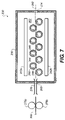
- FIG. 7 is a cross-sectional view illustrating generally another exemplary embodiment of a thermal processor 230 in accordance with the present invention.
- Thermal processor 130 is commonly referred to as a flat-bed type thermal processor and includes a plurality of rollers, such as roller 244 , configured to rotate in a direction as indicated by directional arrow 246 .
- a replaceable tubular sleeve 248 having an outer surface coated with a layer 250 of polymer material is positioned about and selectively coupled to an outer surface of rollers 246 .
- An enclosure 256 forms an oven about roller 244 and tubular sleeves 256 , the oven having an entrance 268 and an exit 274 .
- An upper heat source 242 a and a lower heat source 242 b and 242 b are configured to maintain oven 262 at a desired development temperature.
- a pair of feed rollers, 275 a and 275 , and a media guide 276 are positioned at entrance 268 .
- feed rollers 275 a and 275 b receive and feed a piece of exposed imaging media 300 to media guide 276 .
- Media guide 276 in-turn channels exposed imaging media 300 into oven 262 via entrance 268 .
- Polymer layer 250 contacts exposed imaging media, and the rotation 246 of rollers 244 and tubular sleeves 248 transport the exposed imaging media 300 through oven 262 along a sinusoidal-like transport path 280 .
- imaging media 300 travels along transport path 280 through oven 262 , it is heated to the desired development temperature and, in the process, produces contaminants that over time can accumulate on surfaces within enclosure 256 . In particular, these contaminants can accumulate on polymer layers 250 of tubular sleeves 248 , which are in direct contact with imaging media 300 .
- a qualified technician can periodically replace tubular sleeves 248 in lieu of individually cleaning the outer surfaces of rollers 244 .
- the layer of polymer material can be replaced upon becoming contaminated with byproducts released by the imaging media during development by installing a new sleeve.
- Installation of a new sleeve eliminates problems associated with cleaning the integral polymer surfaces of standard processing drums, such as image defects resulting from nearly inherent variations in the cleanliness of the polymer material after cleaning and undesirable odors associated with cleaning solvents.
- replacement of the sleeve can be completed more quickly than cleaning the integral polymer surfaces of standard processor drums, thereby reducing labor associated with maintenance and processor downtime. Also, since the drum is not being replaced, calibration of associated heaters is not required.
Abstract
Description
- 30 Thermal Processor
- 32 Heated Drum Assembly
- 34 Drive System
- 36 Film Cooling Section
- 38 Densitometer
- 40 Contaminant Removal System
- 41 Sectional View Indicator
- 42 Circumferential Heater
- 44 Heated Drum
- 46 Directional Arrow
- 48 Tubular Sleeve
- 50 Polymer Layer
- 52 Pressure Rollers
- 54 Thickness
- 56 Enclosure
- 58 Upper Cover
- 60 Lower Cover
- 62 Oven
- 64, 66 First Ends
- 68 Entrance Region
- 70, 72 Second Ends
- 74 Exit Region
- 75 a, 75 b Feed Rollers
- 76 Media Guide
- 77 Hinge
- 78 Film Diverter
- 80 Perforated Felt Pad
- 82 Upper Condensation Trap
- 84 Lower Condensation Trap
- 86 Flexible Duct
- 90 Vacuum System
- 92 Fan
- 94 Filter
- 96 Hose
- 100 Imaging Media
- 110, 112 Air Flow Direction
- 120 a, 120 b End Flanges
- 122 a, 122 b Tabs
- 124 a, 124 b Notches
- 126 a, 126 b Set Screws
- 128 a, 128 b Holes
- 130 a, 130 b Threaded Holes
- 141 Sectional View Indicator
- 230 Thermal Processor
- 256 Enclosure
- 262 Oven
- 268 Entrance
- 274 Exit
- 242 a, 242 b Upper and Lower Heat Sources
- 244 Rollers
- 246 Directional Arrow
- 248 Tubular Sleeve
- 250 Polymer Layer
- 275 a, 275 b Feed Rollers
- 276 Media Guide
- 280 Transport Path
- 300 Imaging Media
Claims (15)
Priority Applications (5)
| Application Number | Priority Date | Filing Date | Title |
|---|---|---|---|
| US11/029,593 US7330200B2 (en) | 2005-01-05 | 2005-01-05 | Thermal processor employing replaceable sleeve |
| JP2007549400A JP2008527410A (en) | 2005-01-05 | 2005-12-07 | Heat treatment machine with replaceable sleeve |
| EP05848870A EP1834212B1 (en) | 2005-01-05 | 2005-12-07 | Thermal processor employing replaceable sleeve |
| PCT/US2005/044136 WO2006073658A1 (en) | 2005-01-05 | 2005-12-07 | Thermal processor employing replaceable sleeve |
| DE602005024176T DE602005024176D1 (en) | 2005-01-05 | 2005-12-07 | THERMOPROCESSOR WITH REPLACEABLE MUFF |
Applications Claiming Priority (1)
| Application Number | Priority Date | Filing Date | Title |
|---|---|---|---|
| US11/029,593 US7330200B2 (en) | 2005-01-05 | 2005-01-05 | Thermal processor employing replaceable sleeve |
Publications (2)
| Publication Number | Publication Date |
|---|---|
| US20060146111A1 US20060146111A1 (en) | 2006-07-06 |
| US7330200B2 true US7330200B2 (en) | 2008-02-12 |
Family
ID=36096205
Family Applications (1)
| Application Number | Title | Priority Date | Filing Date |
|---|---|---|---|
| US11/029,593 Expired - Fee Related US7330200B2 (en) | 2005-01-05 | 2005-01-05 | Thermal processor employing replaceable sleeve |
Country Status (5)
| Country | Link |
|---|---|
| US (1) | US7330200B2 (en) |
| EP (1) | EP1834212B1 (en) |
| JP (1) | JP2008527410A (en) |
| DE (1) | DE602005024176D1 (en) |
| WO (1) | WO2006073658A1 (en) |
Cited By (1)
| Publication number | Priority date | Publication date | Assignee | Title |
|---|---|---|---|---|
| US9753429B2 (en) * | 2014-11-11 | 2017-09-05 | Canon Kabushiki Kaisha | Image heating apparatus |
Families Citing this family (4)
| Publication number | Priority date | Publication date | Assignee | Title |
|---|---|---|---|---|
| US20110092930A1 (en) * | 2009-10-20 | 2011-04-21 | TriMountain Medical Resources LLC | Medical protective table sheets |
| US10730317B2 (en) * | 2017-11-15 | 2020-08-04 | Atpcolor S.R.L. | Method and unit for thermosetting printed fabrics |
| IT201800010222A1 (en) | 2018-11-09 | 2020-05-09 | Pmi S R L | ROLLER WITH IMPROVED QUICK RELEASE HUB |
| US20230146996A1 (en) * | 2021-11-05 | 2023-05-11 | J.C. Ford Company | Sheeter with removeable cutting roller sleeve |
Citations (16)
| Publication number | Priority date | Publication date | Assignee | Title |
|---|---|---|---|---|
| US3757662A (en) * | 1970-01-08 | 1973-09-11 | F Ingels | Apparatus for thermic development of heat-sensitive paper |
| US3807616A (en) | 1972-10-25 | 1974-04-30 | H Hope | Removable rollers |
| US4178664A (en) * | 1978-07-17 | 1979-12-18 | Mcloughlin Nelson E | Roller with replaceable sleeve |
| US4992816A (en) | 1988-09-09 | 1991-02-12 | Fuji Photo Film Co., Ltd. | Image recording apparatus and method |
| US5066562A (en) | 1988-03-17 | 1991-11-19 | Fuji Photo Film Co., Ltd. | Method of heating image formation sheet |
| US5296874A (en) | 1990-10-19 | 1994-03-22 | Fuji Photo Film Co., Ltd. | Thermal printer |
| US5468568A (en) * | 1993-04-19 | 1995-11-21 | Hoechst Aktiengesellschaft | Printing roller with a sleeve of thermally wound fiber-reinforced thermoplastics and a plasma-sprayed coating of copper or copper alloy |
| US5946025A (en) | 1997-09-29 | 1999-08-31 | Imation Corp. | Thermal drum processor assembly with roller mounting assembly for a laser imaging device |
| US6007971A (en) | 1992-09-09 | 1999-12-28 | Minnesota Mining And Manufacturing | Apparatus, system, and method for processing photothermographic elements |
| US6285006B1 (en) | 2000-07-12 | 2001-09-04 | American Roller Company | Ceramic heater/fuser roller with internal heater |
| US6393249B1 (en) * | 2000-10-04 | 2002-05-21 | Nexpress Solutions Llc | Sleeved rollers for use in a fusing station employing an internally heated fuser roller |
| US20020135657A1 (en) * | 2001-03-21 | 2002-09-26 | Makoto Sumi | Heat developing apparatus |
| US6541171B1 (en) * | 2000-10-04 | 2003-04-01 | Nexpress Solutions Llc | Sleeved photoconductive member and method of making |
| US6567641B1 (en) * | 2000-10-04 | 2003-05-20 | Nexpress Solutions Llc | Sleeved rollers for use in a fusing station employing an externally heated fuser roller |
| US6582222B1 (en) * | 2002-05-06 | 2003-06-24 | Nexpress Solutions Llc | Fusing station including multilayer fuser roller |
| US20040136707A1 (en) | 2002-12-25 | 2004-07-15 | Makoto Sumi | Thermal development apparatus |
-
2005
- 2005-01-05 US US11/029,593 patent/US7330200B2/en not_active Expired - Fee Related
- 2005-12-07 WO PCT/US2005/044136 patent/WO2006073658A1/en active Application Filing
- 2005-12-07 DE DE602005024176T patent/DE602005024176D1/en active Active
- 2005-12-07 JP JP2007549400A patent/JP2008527410A/en active Pending
- 2005-12-07 EP EP05848870A patent/EP1834212B1/en not_active Expired - Fee Related
Patent Citations (17)
| Publication number | Priority date | Publication date | Assignee | Title |
|---|---|---|---|---|
| US3757662A (en) * | 1970-01-08 | 1973-09-11 | F Ingels | Apparatus for thermic development of heat-sensitive paper |
| US3807616A (en) | 1972-10-25 | 1974-04-30 | H Hope | Removable rollers |
| US4178664A (en) * | 1978-07-17 | 1979-12-18 | Mcloughlin Nelson E | Roller with replaceable sleeve |
| US5066562A (en) | 1988-03-17 | 1991-11-19 | Fuji Photo Film Co., Ltd. | Method of heating image formation sheet |
| US4992816A (en) | 1988-09-09 | 1991-02-12 | Fuji Photo Film Co., Ltd. | Image recording apparatus and method |
| US5091281A (en) | 1988-09-09 | 1992-02-25 | Fuji Photo Film Co., Ltd. | Image recording apparatus and method |
| US5296874A (en) | 1990-10-19 | 1994-03-22 | Fuji Photo Film Co., Ltd. | Thermal printer |
| US6007971A (en) | 1992-09-09 | 1999-12-28 | Minnesota Mining And Manufacturing | Apparatus, system, and method for processing photothermographic elements |
| US5468568A (en) * | 1993-04-19 | 1995-11-21 | Hoechst Aktiengesellschaft | Printing roller with a sleeve of thermally wound fiber-reinforced thermoplastics and a plasma-sprayed coating of copper or copper alloy |
| US5946025A (en) | 1997-09-29 | 1999-08-31 | Imation Corp. | Thermal drum processor assembly with roller mounting assembly for a laser imaging device |
| US6285006B1 (en) | 2000-07-12 | 2001-09-04 | American Roller Company | Ceramic heater/fuser roller with internal heater |
| US6393249B1 (en) * | 2000-10-04 | 2002-05-21 | Nexpress Solutions Llc | Sleeved rollers for use in a fusing station employing an internally heated fuser roller |
| US6541171B1 (en) * | 2000-10-04 | 2003-04-01 | Nexpress Solutions Llc | Sleeved photoconductive member and method of making |
| US6567641B1 (en) * | 2000-10-04 | 2003-05-20 | Nexpress Solutions Llc | Sleeved rollers for use in a fusing station employing an externally heated fuser roller |
| US20020135657A1 (en) * | 2001-03-21 | 2002-09-26 | Makoto Sumi | Heat developing apparatus |
| US6582222B1 (en) * | 2002-05-06 | 2003-06-24 | Nexpress Solutions Llc | Fusing station including multilayer fuser roller |
| US20040136707A1 (en) | 2002-12-25 | 2004-07-15 | Makoto Sumi | Thermal development apparatus |
Cited By (1)
| Publication number | Priority date | Publication date | Assignee | Title |
|---|---|---|---|---|
| US9753429B2 (en) * | 2014-11-11 | 2017-09-05 | Canon Kabushiki Kaisha | Image heating apparatus |
Also Published As
| Publication number | Publication date |
|---|---|
| JP2008527410A (en) | 2008-07-24 |
| US20060146111A1 (en) | 2006-07-06 |
| WO2006073658A1 (en) | 2006-07-13 |
| EP1834212A1 (en) | 2007-09-19 |
| DE602005024176D1 (en) | 2010-11-25 |
| EP1834212B1 (en) | 2010-10-13 |
Similar Documents
| Publication | Publication Date | Title |
|---|---|---|
| US6141512A (en) | Process cartridge having air flow path | |
| EP1834212B1 (en) | Thermal processor employing replaceable sleeve | |
| JP5070182B2 (en) | Image forming apparatus | |
| JP4068770B2 (en) | High temperature pressure fixing device | |
| EP0946898B1 (en) | Apparatus for thermally processing an imaging material employing a system for reducing fogging on the imaging material during thermal processing | |
| US7510596B2 (en) | Thermal processor with contaminant removal cartridge | |
| US7064295B1 (en) | Thermal processor having flexible duct | |
| JP3556152B2 (en) | Image forming device | |
| EP1834213A1 (en) | Media entrance guide in a thermal processor | |
| EP1834211B1 (en) | Thermal processor employing drum and flatbed technologies | |
| JP2006030572A (en) | Image forming apparatus | |
| EP1730590A1 (en) | Preheat chamber for thermal processing | |
| JP2013003507A (en) | Image forming apparatus | |
| JP7206927B2 (en) | image forming device | |
| JPH0545947A (en) | Image forming device | |
| JP2008015313A (en) | Image forming apparatus and transfer device | |
| JP2010117420A (en) | Image forming apparatus | |
| JPH06202508A (en) | Fixing device for image forming device and image forming device | |
| JP2918233B2 (en) | Fixing device | |
| JPH04168471A (en) | Cleaning device | |
| JP2004045950A (en) | Image forming device | |
| JPH10143052A (en) | Image forming device | |
| JP2006071755A (en) | Image forming apparatus | |
| JPH0511171U (en) | Fixing device for image forming apparatus | |
| JPH0571852U (en) | Image forming device |
Legal Events
| Date | Code | Title | Description |
|---|---|---|---|
| AS | Assignment |
Owner name: EASTMAN KODAK COMPANY, NEW YORK Free format text: ASSIGNMENT OF ASSIGNORS INTEREST;ASSIGNOR:VANOUS, JAMES C.;REEL/FRAME:016467/0114 Effective date: 20050412 |
|
| AS | Assignment |
Owner name: CREDIT SUISSE, CAYMAN ISLANDS BRANCH, AS ADMINISTR Free format text: FIRST LIEN OF INTELLECTUAL PROPERTY SECURITY AGREEMENT;ASSIGNOR:CARESTREAM HEALTH, INC.;REEL/FRAME:019649/0454 Effective date: 20070430 Owner name: CREDIT SUISSE, CAYMAN ISLANDS BRANCH, AS ADMINISTR Free format text: SECOND LIEN INTELLECTUAL PROPERTY SECURITY AGREEME;ASSIGNOR:CARESTREAM HEALTH, INC.;REEL/FRAME:019773/0319 Effective date: 20070430 |
|
| STCF | Information on status: patent grant |
Free format text: PATENTED CASE |
|
| AS | Assignment |
Owner name: CARESTREAM HEALTH, INC., NEW YORK Free format text: ASSIGNMENT OF ASSIGNORS INTEREST;ASSIGNOR:EASTMAN KODAK COMPANY;REEL/FRAME:020741/0126 Effective date: 20070501 Owner name: CARESTREAM HEALTH, INC., NEW YORK Free format text: ASSIGNMENT OF ASSIGNORS INTEREST;ASSIGNOR:EASTMAN KODAK COMPANY;REEL/FRAME:020756/0500 Effective date: 20070501 Owner name: CARESTREAM HEALTH, INC.,NEW YORK Free format text: ASSIGNMENT OF ASSIGNORS INTEREST;ASSIGNOR:EASTMAN KODAK COMPANY;REEL/FRAME:020741/0126 Effective date: 20070501 Owner name: CARESTREAM HEALTH, INC.,NEW YORK Free format text: ASSIGNMENT OF ASSIGNORS INTEREST;ASSIGNOR:EASTMAN KODAK COMPANY;REEL/FRAME:020756/0500 Effective date: 20070501 |
|
| AS | Assignment |
Owner name: CARESTREAM HEALTH, INC., NEW YORK Free format text: RELEASE OF SECURITY INTEREST IN INTELLECTUAL PROPERTY (FIRST LIEN);ASSIGNOR:CREDIT SUISSE AG, CAYMAN ISLANDS BRANCH;REEL/FRAME:026069/0012 Effective date: 20110225 |
|
| AS | Assignment |
Owner name: CREDIT SUISSE AG, CAYMAN ISLANDS BRANCH, NEW YORK Free format text: INTELLECTUAL PROPERTY SECURITY AGREEMENT;ASSIGNORS:CARESTREAM HEALTH, INC.;CARESTREAM DENTAL, LLC;QUANTUM MEDICAL IMAGING, L.L.C.;AND OTHERS;REEL/FRAME:026269/0411 Effective date: 20110225 |
|
| FPAY | Fee payment |
Year of fee payment: 4 |
|
| AS | Assignment |
Owner name: CARESTREAM HEALTH, INC., NEW YORK Free format text: RELEASE OF SECURITY INTEREST IN INTELLECTUAL PROPERTY (SECOND LIEN);ASSIGNOR:CREDIT SUISSE AG, CAYMAN ISLANDS BRANCH;REEL/FRAME:027851/0812 Effective date: 20110225 |
|
| AS | Assignment |
Owner name: CREDIT SUISSE AG, CAYMAN ISLANDS BRANCH, NEW YORK Free format text: AMENDED AND RESTATED INTELLECTUAL PROPERTY SECURITY AGREEMENT (FIRST LIEN);ASSIGNORS:CARESTREAM HEALTH, INC.;CARESTREAM DENTAL LLC;QUANTUM MEDICAL IMAGING, L.L.C.;AND OTHERS;REEL/FRAME:030711/0648 Effective date: 20130607 |
|
| AS | Assignment |
Owner name: CREDIT SUISSE AG, CAYMAN ISLANDS BRANCH, NEW YORK Free format text: SECOND LIEN INTELLECTUAL PROPERTY SECURITY AGREEMENT;ASSIGNORS:CARESTREAM HEALTH, INC.;CARESTREAM DENTAL LLC;QUANTUM MEDICAL IMAGING, L.L.C.;AND OTHERS;REEL/FRAME:030724/0154 Effective date: 20130607 |
|
| FPAY | Fee payment |
Year of fee payment: 8 |
|
| FEPP | Fee payment procedure |
Free format text: MAINTENANCE FEE REMINDER MAILED (ORIGINAL EVENT CODE: REM.); ENTITY STATUS OF PATENT OWNER: LARGE ENTITY |
|
| LAPS | Lapse for failure to pay maintenance fees |
Free format text: PATENT EXPIRED FOR FAILURE TO PAY MAINTENANCE FEES (ORIGINAL EVENT CODE: EXP.); ENTITY STATUS OF PATENT OWNER: LARGE ENTITY |
|
| STCH | Information on status: patent discontinuation |
Free format text: PATENT EXPIRED DUE TO NONPAYMENT OF MAINTENANCE FEES UNDER 37 CFR 1.362 |
|
| FP | Lapsed due to failure to pay maintenance fee |
Effective date: 20200212 |
|
| AS | Assignment |
Owner name: TROPHY DENTAL INC., GEORGIA Free format text: RELEASE BY SECURED PARTY;ASSIGNOR:CREDIT SUISSE AG, CAYMAN ISLANDS BRANCH;REEL/FRAME:061681/0380 Effective date: 20220930 Owner name: QUANTUM MEDICAL HOLDINGS, LLC, NEW YORK Free format text: RELEASE BY SECURED PARTY;ASSIGNOR:CREDIT SUISSE AG, CAYMAN ISLANDS BRANCH;REEL/FRAME:061681/0380 Effective date: 20220930 Owner name: QUANTUM MEDICAL IMAGING, L.L.C., NEW YORK Free format text: RELEASE BY SECURED PARTY;ASSIGNOR:CREDIT SUISSE AG, CAYMAN ISLANDS BRANCH;REEL/FRAME:061681/0380 Effective date: 20220930 Owner name: CARESTREAM DENTAL, LLC, GEORGIA Free format text: RELEASE BY SECURED PARTY;ASSIGNOR:CREDIT SUISSE AG, CAYMAN ISLANDS BRANCH;REEL/FRAME:061681/0380 Effective date: 20220930 Owner name: CARESTREAM HEALTH, INC., NEW YORK Free format text: RELEASE BY SECURED PARTY;ASSIGNOR:CREDIT SUISSE AG, CAYMAN ISLANDS BRANCH;REEL/FRAME:061681/0380 Effective date: 20220930 Owner name: TROPHY DENTAL INC., GEORGIA Free format text: RELEASE OF SECURITY INTEREST IN INTELLECTUAL PROPERTY (SECOND LIEN);ASSIGNOR:CREDIT SUISSE AG, CAYMAN ISLANDS BRANCH;REEL/FRAME:061683/0601 Effective date: 20220930 Owner name: QUANTUM MEDICAL IMAGING, L.L.C., NEW YORK Free format text: RELEASE OF SECURITY INTEREST IN INTELLECTUAL PROPERTY (SECOND LIEN);ASSIGNOR:CREDIT SUISSE AG, CAYMAN ISLANDS BRANCH;REEL/FRAME:061683/0601 Effective date: 20220930 Owner name: CARESTREAM DENTAL LLC, GEORGIA Free format text: RELEASE OF SECURITY INTEREST IN INTELLECTUAL PROPERTY (SECOND LIEN);ASSIGNOR:CREDIT SUISSE AG, CAYMAN ISLANDS BRANCH;REEL/FRAME:061683/0601 Effective date: 20220930 Owner name: CARESTREAM HEALTH, INC., NEW YORK Free format text: RELEASE OF SECURITY INTEREST IN INTELLECTUAL PROPERTY (SECOND LIEN);ASSIGNOR:CREDIT SUISSE AG, CAYMAN ISLANDS BRANCH;REEL/FRAME:061683/0601 Effective date: 20220930 Owner name: TROPHY DENTAL INC., NEW YORK Free format text: RELEASE OF SECURITY INTEREST IN INTELLECTUAL PROPERTY (FIRST LIEN);ASSIGNOR:CREDIT SUISSE AG, CAYMAN ISLANDS BRANCH;REEL/FRAME:061683/0441 Effective date: 20220930 Owner name: QUANTUM MEDICAL IMAGING, L.L.C., NEW YORK Free format text: RELEASE OF SECURITY INTEREST IN INTELLECTUAL PROPERTY (FIRST LIEN);ASSIGNOR:CREDIT SUISSE AG, CAYMAN ISLANDS BRANCH;REEL/FRAME:061683/0441 Effective date: 20220930 Owner name: CARESTREAM DENTAL LLC, GEORGIA Free format text: RELEASE OF SECURITY INTEREST IN INTELLECTUAL PROPERTY (FIRST LIEN);ASSIGNOR:CREDIT SUISSE AG, CAYMAN ISLANDS BRANCH;REEL/FRAME:061683/0441 Effective date: 20220930 Owner name: CARESTREAM HEALTH, INC., NEW YORK Free format text: RELEASE OF SECURITY INTEREST IN INTELLECTUAL PROPERTY (FIRST LIEN);ASSIGNOR:CREDIT SUISSE AG, CAYMAN ISLANDS BRANCH;REEL/FRAME:061683/0441 Effective date: 20220930 |