US7338393B2 - Dimples comprised of two or more intersecting surfaces - Google Patents
Dimples comprised of two or more intersecting surfaces Download PDFInfo
- Publication number
- US7338393B2 US7338393B2 US11/551,982 US55198206A US7338393B2 US 7338393 B2 US7338393 B2 US 7338393B2 US 55198206 A US55198206 A US 55198206A US 7338393 B2 US7338393 B2 US 7338393B2
- Authority
- US
- United States
- Prior art keywords
- cylinders
- dimple
- radius
- dimples
- golf ball
- Prior art date
- Legal status (The legal status is an assumption and is not a legal conclusion. Google has not performed a legal analysis and makes no representation as to the accuracy of the status listed.)
- Active
Links
Images


Classifications
-
- A—HUMAN NECESSITIES
- A63—SPORTS; GAMES; AMUSEMENTS
- A63B—APPARATUS FOR PHYSICAL TRAINING, GYMNASTICS, SWIMMING, CLIMBING, OR FENCING; BALL GAMES; TRAINING EQUIPMENT
- A63B37/00—Solid balls; Rigid hollow balls; Marbles
- A63B37/0003—Golf balls
- A63B37/0004—Surface depressions or protrusions
- A63B37/0007—Non-circular dimples
-
- A—HUMAN NECESSITIES
- A63—SPORTS; GAMES; AMUSEMENTS
- A63B—APPARATUS FOR PHYSICAL TRAINING, GYMNASTICS, SWIMMING, CLIMBING, OR FENCING; BALL GAMES; TRAINING EQUIPMENT
- A63B37/00—Solid balls; Rigid hollow balls; Marbles
- A63B37/0003—Golf balls
- A63B37/0004—Surface depressions or protrusions
- A63B37/0006—Arrangement or layout of dimples
- A63B37/00065—Arrangement or layout of dimples located around the pole or the equator
-
- A—HUMAN NECESSITIES
- A63—SPORTS; GAMES; AMUSEMENTS
- A63B—APPARATUS FOR PHYSICAL TRAINING, GYMNASTICS, SWIMMING, CLIMBING, OR FENCING; BALL GAMES; TRAINING EQUIPMENT
- A63B37/00—Solid balls; Rigid hollow balls; Marbles
- A63B37/0003—Golf balls
- A63B37/0004—Surface depressions or protrusions
- A63B37/0012—Dimple profile, i.e. cross-sectional view
- A63B37/0015—Dimple profile, i.e. cross-sectional view with sub-dimples formed within main dimples
-
- A—HUMAN NECESSITIES
- A63—SPORTS; GAMES; AMUSEMENTS
- A63B—APPARATUS FOR PHYSICAL TRAINING, GYMNASTICS, SWIMMING, CLIMBING, OR FENCING; BALL GAMES; TRAINING EQUIPMENT
- A63B37/00—Solid balls; Rigid hollow balls; Marbles
- A63B37/0003—Golf balls
- A63B37/0004—Surface depressions or protrusions
- A63B37/0019—Specified dimple depth
-
- A—HUMAN NECESSITIES
- A63—SPORTS; GAMES; AMUSEMENTS
- A63B—APPARATUS FOR PHYSICAL TRAINING, GYMNASTICS, SWIMMING, CLIMBING, OR FENCING; BALL GAMES; TRAINING EQUIPMENT
- A63B37/00—Solid balls; Rigid hollow balls; Marbles
- A63B37/0003—Golf balls
- A63B37/0004—Surface depressions or protrusions
- A63B37/00215—Volume ratio
Definitions
- the present invention relates to a new golf ball dimple configuration comprised of two or more intersecting surfaces.
- the intersecting surfaces are cylindrical.
- Dimples are provided in the surface of a golf ball in order to control and improve the flight of the ball.
- the dimples serve to reduce the pressure differential between the front and rear of the ball as it rotates and travels through the air.
- One basic criteria for the use of dimples is maximize the surface coverage of dimples on the ball without diminishing the aerodynamic symmetry of the ball.
- Golf balls are produced having various dimple patterns, dimple sizes, and dimple configurations so as to have a substantially constant geometric surface while improving the flight characteristics of the ball.
- the dimple has a bottom surface including multiple portions defined by at least two intersecting surfaces. Each portion of the dimple bottom corresponds with one surface.
- the surfaces are preferably cylindrical, and three such surfaces are provided.
- the first bottom portion of the dimple is defined by a first cylinder having a first radius, and second and third bottom portions are defined by second and third cylinders having equal radii which are less than the radius of the first cylinder.
- tri-cylinders intersect to define a geometric configuration used to form the dimple bottom surface.
- Each tri-cylinder is defined by the intersection of one large radius and two small radius cylinders as set forth above.
- the dimple configuration may also be defined by a tetrahedron formed by the intersection of at least three surfaces.
- the intersecting surfaces may be planar or curved, such as portions of a sphere or cylinder.
- the top of the tetrahedron is truncated by a planar or curved surface to define the geometric configuration of the dimple.
- the resulting dimples may have a triangular, quadrangular, pentagonal or hexagonal shape where the dimple volumes meet the surface of the golf ball.
- Such dimples are provided in a golf ball surface. All of the dimples in the ball surface may have the same configuration, or a variety of dimples of different configurations may be provided in the ball surface to maximize dimple coverage thereon.
- the dimples can also be arranged in the surface in a geometric pattern.
- FIG. 1 is sectional view of a golf ball having a conventional circular dimple as known in the art.
- FIG. 2 is a perspective view of a regular dual radius tri-cylinder and its circumscribed prism according to the invention.
- FIG. 3 is a perspective view of a regular bi-cylinder and its circumscribed prism according to the invention.
- FIG. 4 is a perspective view of a regular tri-semicylinder and its circumscribed prism according to the invention.
- FIG. 5 is a plan view of a golf ball and three intersecting cylinders showing the correlation between the intersection of the surfaces of the cylinders with the golf ball surface.
- FIG. 6 is a detailed view of the golf ball of FIG. 5 showing two smaller radius cylinders intersecting the golf ball surface and which are tangent to a large cylinder.
- FIG. 7 is a cross-sectional view of the dimple formed using the three intersecting cylinders of FIGS. 5 and 6 .
- FIGS. 8 , 9 , and 10 are bottom views, respectively, of three dual radius cylinders used to form a dimple geometry according to another embodiment of the invention.
- FIGS. 11 , 12 , and 13 are side views of the dual radius cylinders of FIGS. 8 , 9 , and 10 , respectively.
- FIG. 14 is a bottom view of the dual radius cylinders of FIGS. 8 , 9 and 10 showing their orientation prior to intersection.
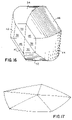
- FIG. 15 is a bottom view of the geometric configuration defined by intersecting portions of the dual radius cylinders of FIG. 14 .
- FIG. 16 is a detailed perspective view of the volume of a dimple formed using the geometric configuration shown in FIG. 15 .
- FIG. 17 is a detailed perspective view of the dimple volume formed using penta-semi-cylindrical geometry.
- FIG. 18A is a partial plan view of a golf ball including dimples configured with a geometry based on the dual radius cylinder of FIG. 15 .
- FIG. 18B is a detailed plan view of a dimple from the golf ball of FIG. 18A .
- FIG. 19 is a plan view of a golf ball containing dual radii penta-semi-cylindrical dimples, symmetric dual radii tri-cylindrical dimples, and non-symmetric dual radii tri-cylindrical dimples formed in accordance with the invention.
- FIG. 20 is a top plan view of a tetrahedral volume formed by intersecting planar surfaces used to form a dimple geometry according to the invention.
- FIGS. 21-23 are top plan views of the tetrahedral volume of FIG. 20 where the top portion of the volume has been truncated in accordance with the invention.
- FIGS. 24-27 are sectional views taken along lines 24 - 24 , 25 - 25 , 26 - 26 and 27 - 27 of FIGS. 20-23 , respectively, showing the resulting cross-sectional dimple configurations thereof.
- FIG. 28 is a top plan view of a tetrahedral volume formed by intersecting curved surfaces used to form a dimple geometry according to the invention.
- FIGS. 29-31 are top plan views of the tetrahedral volume of FIG. 28 where the top portion of the volume has been truncated in accordance with the invention.
- FIGS. 32-35 are sectional views taken along lines 32 - 32 , 33 - 33 , 34 - 34 and 35 - 35 of FIGS. 28 - 31 , respectively, showing the resulting cross-sectional dimple configurations thereof and
- FIG. 36 is a plan view of a golf ball having dimples formed using a truncated tetrehedtal volume geometry.
- FIG. 1 there is shown the cross.-sectional configuration of a conventional circular dimple 2 in the surface of a golf ball 4 .
- the dimple has a diameter D and a depth d.
- a circular dimple can be thought of as being created by the intersection of a spherical surface with the surface of a golf ball, with the radius of the dimple being defined by the radius of the sphere.
- the present invention relates to non-circular dimple geometries formed by intersecting surfaces, such as for example, cylindrical and planar surfaces. Intersecting cylinders form tri-cylinders, tri-semicylinders, bi-cylinders, quad-semicylinders or more generally n-cylinders. Dimple volumes are formed by the intersecting n cylinders, with their long axes coplanar and equal angles between those long axes.
- the intersecting cylinders may have a pair of smaller cylinders tangent to the larger cylinder on each side to form edge radii of the dimple.
- This is similar to a dual radius dimple profile.
- a dual radius dimple is formed with a larger spherical radius (as the bottom of the dimple) tangent to a torus of smaller radius (forming an edge radius).
- the dual radius n-cylinder dimple bottom is formed by n cylinders and the edge radius is formed by a pair of smaller cylinders tangent to each of the larger cylinders.
- These are called dual radius tri-cylinders, tri-semicylinders, bi-cylinders, and quad-semicylinders.
- the dimples volumes are formed by the intersecting n cylinders (each with a pair of smaller tangent cylinders), with their long axes coplanar and equal angles between those long axes. If the radii of the cylinders used to form these shapes are the same, the shape is regular. Two dimensional cross-sections of these volumes (cut parallel to the plane of the long axes) are regular 2n-gons, e.g. a regular polygon of 2 ⁇ n sides.
- FIGS. 2 , 3 , and 4 Examples of the geometries used to create dimples in accordance with the invention are shown in FIGS. 2 , 3 , and 4 . More particularly, FIG. 2 shows the geometry defined by the intersection of three cylinders of the same diameter and is referred to as a symmetric tri-cylinder 6 . The hexagonal prism circumscribed by the tri-cylinder is shown in phantom. Tri-cylinders are formed from three cylinders oriented 120 ⁇ apart with a common axis of rotation central to the dimple volume. The configuration of the two-dimensional cross-section is a hexagon. When this volume is removed from a sphere to form a dimple, the intersecting surface is not planar, but rather resembles a hexagon having curved edges.
- FIG. 3 shows the geometry defined by the intersection of two cylinders of the same diameter and is a symmetric bi-cylinder 8 with the circumscribed square prism shown in phantom.
- Bi-cylinders are formed from two cylinders oriented 90 ⁇ apart with a common axis of rotation central to the dimple volume.
- the configuration of the two-dimensional cross-sections are not squares. When this volume is removed from a sphere to form a dimple, the intersecting surface is not planar, but rather resembles a square having curved edges.
- FIG. 4 shows the geometry defined by the intersection of three eccentric cylinders, i.e. a tri-semicylinder 10 with a triangular circumscribed prism shown in phantom.
- Tri-semicylinders are formed from three cylinders oriented 120 ⁇ apart with a common axis of rotation that is eccentric from the geometric center of the dimple volume.
- the configuration of the two-dimensional cross-sections is a triangle. When this volume is removed from a sphere to form a dimple, the intersecting surface is not planar, but rather resembles a triangle having curved edges.
- Quad-cylinders are formed from four cylinders oriented 45 ⁇ apart with a common axis of rotation central to the dimple volume.
- the configuration of the two-dimensional cross-sections is an octagon. When this volume is removed from a sphere to form a dimple, the intersecting surface is not planar, but rather resembles an octagon having curved edges.
- FIGS. 5-7 there are shown dual radius cylinders used to form a further geometry for a further dimple configuration.
- a first cylinder 12 ( FIG. 5 ) has a first radius R 12 which is used to define the bottom portion 14 of a dimple 16 in the surface of a golf ball 18 shown in FIG. 7 . That is, the bottom portion 14 of the dimple 16 has a radius R 12 .
- Second 20 and third 22 cylinders each have radii R 20 and R 22 which are significantly less than the radius R 12 of the first cylinder. In the preferred example shown, the radii R 20 and R 22 are equal. However, they may be different so long as they both are less than the radius R 12 .
- the second and third cylinders are arranged at an outer edge of the first cylinder as shown in FIG. 5 , with the axes of all of the cylinders being parallel.
- the surfaces of second 20 and third 22 cylinders intersect the golf ball surface and thus define dimple bottom portions 24 and 26 , respectively.
- the bottom portion 24 has a radius R 20 from the second cylinder 20 and the bottom portion 26 has a radius R 22 from the third cylinder 22 .
- the second and third cylinders overlap so that all three cylinders intersect and are tangent at the intersection.
- the intersection of the surfaces of the cylinders with the golf ball surface define the geometric configuration of the dimple bottom surface.
- the degree of overlap of the second and third cylinders will define the width of the dimple.
- the golf ball 18 has X, Y, and Z axes and is centered at (0,0,0).
- the first cylinder 12 that forms the bottom of the dimple has its radius parallel with the Z-axis of the ball and is centered at (0, YE, 0).
- the edge cylinders i.e. the second 20 and third 22 cylinders are created. These cylinders have their radii centered at (XC, YC) and ( ⁇ XC, YC), respectively.
- the surface of the three solids defined by the joinder of the three cylinders defines the geometry of the dimple.
- This geometry can be used to create a dimple volume removal tool which is used to create a ball geometry for forming the dimples during molding of the cover layer of the golf ball.
- the dimple defined by the intersecting cylindrical surfaces is referred to as a dual radius cylinder dimple.
- the first cylinder 12 has a first radius and the second and third cylinders 20 , 22 have a second radius.
- FIGS. 8 is a bottom view of a dual radius cylinder 28 including a large diameter cylinder portion 30 and two small diameter cylinder portions 32 , 34 , small cylinder portions having equal radii.
- the small diameter cylinder portions define the edge of a dimple the large diameter cylinder portion defines the bottom of a dimple.
- the large diameter cylinder portion may be referred to as the bottom cylinder and the small diameter cylinder portions may be referred to as the edge cylinders.
- FIG. 9 is a bottom view of a dual radius cylinder 36 including bottom cylinder 38 and edge cylinders 40 , 42
- FIG. 10 is a bottom view of a dual radius cylinder 44 including bottom cylinder 46 and edge cylinders 48 , 50 .
- the dual radius cylinders 36 and 44 are similar to the dual radius cylinder 28 .
- FIGS. 11-13 are side views of the dual radius cylinders 28 , 36 , and 44 of FIGS. 8-10 , respectively.
- FIG. 14 shows the orientation of the dual radius cylinders 28 , 36 , and 44 prior to intersection and FIG. 15 is a detailed bottom view of the geometry defined by the intersection of the surfaces of the dual radius cylinders.
- FIG. 15 all volumes of the dual radius cylinders which do not intersect have been removed to define the geometry as shown.
- a perspective view of the intersection geometry of FIG. 15 is shown in FIG. 16 . It represents the volume of a dimple formed using the geometry.
- the portions 30 , 38 and 46 are formed by the bottom cylindrical surface of the dual radius cylinders and define the bottom surface of the dimple and the portions 32 , 34 , 40 , 42 , 48 , and 50 are formed by the edge cylindrical surfaces of the dual radius cylinders and define the edge surfaces of the dimple.
- FIG. 17 is a perspective view of a dual radius penta-semicylinder dimple.
- FIG. 18A shows a golf ball surface 52 having dimples 54 defined by a symmetric tri-cylinder as shown in FIG. 15 formed of dual radius cylinders as shown in FIG. 14 .
- the upper portion of the tri-cylinder has six surfaces, two each of surfaces 30 , 38 , and 46 .
- Each dimple 54 in the ball of FIG. 18A also has six surfaces 54 a - f corresponding to the upper surfaces of the tri-cylinder, respectively, as shown in FIG. 18B .
- the mid-portion of the tri-cylinder has another six surfaces 32 , 34 , 40 , 42 , 48 , and 50 which form the surfaces 54 g - l in the dimple 54 in FIG. 18B .
- the dimples can be sized and arranged on the ball surface in a desired pattern to maximize dimple coverage on the ball surface.
- the size and depth of the dimples is defined by the radii of the cylinders being used to create the geometries.
- a common design practice of placing dimples onto a golf ball is to begin at either the equator and work toward the pole, begin at the pole and work toward the equator, or begin at both the pole and equator and work toward the other simultaneously. It is also common that the preferred dimple sizes may not maximize surface area coverage.
- a variation to the n-cylinder (bi, tri, quad, penta etc.) may be employed which in effect stretches the dimple in at least one direction, similar to the way in which a circular dimple would be stretched into an ellipse. Such stretching could also result in a non-symmetric dimple. This is done to maximize surface area coverage and to create a cosmetically attractive layout.
- the dimple volumes can be combined to form dimple patterns with increased dimple coverage on the surface of a golf ball.
- these new dimple shapes have edge angles, volumes, depths, and chordal diameters similar to traditional spherical dimples.
- Individual dimple volumes can be tuned to match volume ratios that work for traditional spherical dimple patterns.
- the pair of smaller tangential cylinders allows the dimple volume and dimple edge angle to be adjusted independently.
- a golf ball 56 including dimples formed in accordance with a preferred embodiment of the invention is shown in FIG. 19 .
- the golf ball includes 12 dual radius penta-semicylinder dimples 58 , 50 symmetric dual radius tri-cylinder dimples 60 , and 260 non-symmetric dual radius tri-cylinder dimples 62 .
- the pattern is repeated five times across the surface of the golf ball (i.e. five-fold symmetry) and provides 90.3% dimple surface coverage.
- intersecting surfaces may also be used to define the geometry used to create dimple configurations in accordance with the invention.
- FIGS. 20-23 three planar surfaces intersect to form a tetrahedral volume. The top of the tetrahedron can be used to form the dimple geometry.
- the volume of FIG. 20 is a full tetrahedron 64 .
- the cross-section of the tetrahedron taken along line 24 - 24 produces the dimple cross-sectional configuration shown in FIG. 24 .
- the volume of FIG. 21 is a truncated tetrahedron 66 .
- the top of the tetrahedron is truncated by a fourth planar surface which is parallel to the plane of the bottom of the tetrahedron.
- the cross-section of the tetrahedron 66 taken along line 25 - 25 produces the dimple cross-sectional configuration shown in FIG. 25 .
- the volume of FIG. 22 is a truncated tetrahedron 68 .
- the top of the tetrahedron is truncated by a fourth convex surface.
- the cross-section of the tetrahedron 68 taken along line 26 - 26 produces the dimple cross-sectional configuration shown in FIG. 26 .
- the volume of FIG. 23 is a truncated tetrahedron 70 .
- the top of the tetrahedron is truncated by a fourth concave surface.
- the cross-section of the tetrahedron 70 taken along line 27 - 27 produces the dimple cross-sectional configuration shown in FIG. 27 .
- FIGS. 28-31 are similar to FIGS. 20-23 except that the tetrahedral volumes are defined by curved rather than planar surfaces.
- the curves may be portions of a sphere or cylinder or other curved geometric shape.
- the truncations in FIGS. 29-31 are formed by planar, concave, and convex surfaces, respectively, in the same manner as the truncations in FIGS. 21-23 .
- the dimple configurations resulting from cross-sections taken along lines 32 - 32 , 33 - 33 , 34 - 34 , and 35 - 35 are shown in FIGS. 32 , 33 , 34 , and 35 , respectively.
- FIG. 36 a golf ball containing triangular dimples 72 with planar sides.
- the bottom surfaces of the dimples are formed by a sphere concentric with the golf ball surface but having a slightly smaller diameter than the golf ball. Where the edges of the dimples meet, small fillet radii are provided to round off the transition between adjacent dimples.
- Such a dimple pattern provides 93.86% coverage of the golf ball surface where the dimple depth is 0.006 inches, the ball radius is 1.693 inches, the edge angle is 15.25 ⁇ , and the total volume ratio is 1.45%.
Abstract
Description
Claims (10)
Priority Applications (1)
| Application Number | Priority Date | Filing Date | Title |
|---|---|---|---|
| US11/551,982 US7338393B2 (en) | 2003-08-18 | 2006-10-23 | Dimples comprised of two or more intersecting surfaces |
Applications Claiming Priority (3)
| Application Number | Priority Date | Filing Date | Title |
|---|---|---|---|
| US49610603P | 2003-08-18 | 2003-08-18 | |
| US10/920,591 US7128666B2 (en) | 2003-08-18 | 2004-08-18 | Dimples comprised of two or more intersecting surfaces |
| US11/551,982 US7338393B2 (en) | 2003-08-18 | 2006-10-23 | Dimples comprised of two or more intersecting surfaces |
Related Parent Applications (1)
| Application Number | Title | Priority Date | Filing Date |
|---|---|---|---|
| US10/920,591 Division US7128666B2 (en) | 2003-08-18 | 2004-08-18 | Dimples comprised of two or more intersecting surfaces |
Publications (2)
| Publication Number | Publication Date |
|---|---|
| US20070042838A1 US20070042838A1 (en) | 2007-02-22 |
| US7338393B2 true US7338393B2 (en) | 2008-03-04 |
Family
ID=34198091
Family Applications (2)
| Application Number | Title | Priority Date | Filing Date |
|---|---|---|---|
| US10/920,591 Active 2024-09-21 US7128666B2 (en) | 2003-08-18 | 2004-08-18 | Dimples comprised of two or more intersecting surfaces |
| US11/551,982 Active US7338393B2 (en) | 2003-08-18 | 2006-10-23 | Dimples comprised of two or more intersecting surfaces |
Family Applications Before (1)
| Application Number | Title | Priority Date | Filing Date |
|---|---|---|---|
| US10/920,591 Active 2024-09-21 US7128666B2 (en) | 2003-08-18 | 2004-08-18 | Dimples comprised of two or more intersecting surfaces |
Country Status (1)
| Country | Link |
|---|---|
| US (2) | US7128666B2 (en) |
Cited By (8)
| Publication number | Priority date | Publication date | Assignee | Title |
|---|---|---|---|---|
| US20170136305A1 (en) * | 2015-11-16 | 2017-05-18 | Acushnet Company | Golf ball dimple plan shape |
| US20170136308A1 (en) * | 2015-11-16 | 2017-05-18 | Acushnet Company | Golf ball dimple plan shape |
| US20170136307A1 (en) * | 2015-11-16 | 2017-05-18 | Acushnet Company | Golf ball dimple plan shapes and methods of generating same |
| US20180193703A1 (en) * | 2015-11-16 | 2018-07-12 | Acushnet Company | Golf ball dimple plan shape |
| US10486028B2 (en) * | 2015-11-16 | 2019-11-26 | Acushnet Company | Golf ball dimple plan shape |
| US10814176B2 (en) * | 2015-11-16 | 2020-10-27 | Acushnet Company | Golf ball dimple plan shape |
| US11117021B2 (en) * | 2015-11-16 | 2021-09-14 | Acushnet Company | Golf ball dimple plan shape |
| US11207571B2 (en) * | 2015-11-16 | 2021-12-28 | Acushnet Company | Golf ball dimple plan shape |
Families Citing this family (18)
| Publication number | Priority date | Publication date | Assignee | Title |
|---|---|---|---|---|
| US7354358B2 (en) * | 2005-07-15 | 2008-04-08 | Bridgestone Sports Co., Ltd. | Golf ball |
| US7390272B2 (en) * | 2006-06-30 | 2008-06-24 | Bridgestone Sports Co., Ltd. | Golf ball |
| US7559857B2 (en) * | 2007-10-31 | 2009-07-14 | Bridgestone Sports Co., Ltd. | Golf ball |
| US8083614B2 (en) | 2009-02-20 | 2011-12-27 | Bridgestone Sports Co., Ltd. | Golf ball and method for designing same |
| US8317638B2 (en) * | 2009-09-09 | 2012-11-27 | Acushnet Company | Golf ball dimples having circumscribed prismatoids |
| US20110269577A1 (en) * | 2010-04-28 | 2011-11-03 | Aero-X Golf Inc. | nonconforming anti-slice ball |
| US20150119171A1 (en) | 2010-12-22 | 2015-04-30 | Acushnet Company | Golf ball dimples defined by superposed curves |
| US10232223B2 (en) | 2010-12-22 | 2019-03-19 | Acushnet Company | Golf ball dimples defined by superposed curves |
| US9782630B2 (en) * | 2010-12-22 | 2017-10-10 | Acushnet Company | Golf ball dimples defined by superposed curves |
| US10758785B2 (en) | 2010-12-22 | 2020-09-01 | Acushnet Company | Golf ball dimples defined by superposed curves |
| US8894510B2 (en) * | 2012-12-31 | 2014-11-25 | Acushnet Company | Golf ball dimple profile |
| US9297714B2 (en) | 2013-03-05 | 2016-03-29 | Rosemount Aerospace Inc. | Air data probes |
| US9341533B2 (en) | 2013-03-05 | 2016-05-17 | Rosemount Aerospace Inc. | Air data probes |
| RU2542791C1 (en) * | 2013-08-29 | 2015-02-27 | Федеральное государственное унитарное предприятие "Центральный аэрогидродинамический институт имени профессора Н.Е. Жуковского" (ФГУП "ЦАГИ") | Air pressure intake |
| US9878212B2 (en) * | 2015-12-29 | 2018-01-30 | Acushnet Company | Golf ball dimple shape |
| JP7238382B2 (en) * | 2018-12-19 | 2023-03-14 | 住友ゴム工業株式会社 | Golf ball |
| US11813500B2 (en) * | 2022-03-23 | 2023-11-14 | Acushnet Company | Fan-shaped golf ball dimple |
| US20230372779A1 (en) * | 2022-05-18 | 2023-11-23 | Acushnet Company | Golf ball dimple constructed of radial channels |
Citations (36)
| Publication number | Priority date | Publication date | Assignee | Title |
|---|---|---|---|---|
| US1418220A (en) | 1920-10-22 | 1922-05-30 | White John | Golf ball |
| US2861810A (en) | 1954-12-10 | 1958-11-25 | Veatch Franklin | Golf ball |
| US4090716A (en) | 1971-06-25 | 1978-05-23 | Uniroyal, Inc. | Golf ball |
| US4830378A (en) | 1987-01-28 | 1989-05-16 | Wilson Sporting Goods Co. | Golf ball with uniform land configuration |
| US4836552A (en) | 1984-03-12 | 1989-06-06 | Macgregor Golf Company | Short distance golf ball |
| US4840381A (en) | 1986-03-20 | 1989-06-20 | Bridgestone Corporation | Golf ball |
| US4869512A (en) | 1986-11-19 | 1989-09-26 | Bridgestone Corporation | Golf ball |
| US5024444A (en) | 1988-12-02 | 1991-06-18 | Bridgestone Corporation | Golf ball |
| US5080367A (en) | 1972-03-20 | 1992-01-14 | Acushnet Company | Golf ball |
| US5174578A (en) | 1990-12-19 | 1992-12-29 | Sumitomo Rubber Industries, Ltd. | Golf ball |
| US5338039A (en) | 1991-10-08 | 1994-08-16 | Sumitomo Rubber Industries, Ltd. | Golf ball |
| US5470076A (en) | 1993-02-17 | 1995-11-28 | Dunlop Slazenger Corporation | Golf ball |
| US5536013A (en) | 1993-06-23 | 1996-07-16 | Hansberger Precision Golf Incorporated | Golf ball |
| US5564708A (en) | 1994-09-06 | 1996-10-15 | Ilya Co., Ltd. | Golf ball |
| US5722903A (en) | 1995-01-13 | 1998-03-03 | Sumitomo Rubber Industries, Ltd. | Golf ball |
| US5779563A (en) | 1996-02-09 | 1998-07-14 | Bridgestone Sports Co., Ltd. | Multi-piece solid golf ball |
| US5842937A (en) | 1997-10-22 | 1998-12-01 | Acushnet Company | Golf ball with surface texture defined by fractal geometry |
| US5984807A (en) | 1998-08-20 | 1999-11-16 | Callaway Golf Company | Golf ball |
| US6039660A (en) | 1997-08-15 | 2000-03-21 | Bridgestone Sports Co., Ltd. | Golf ball |
| US6053820A (en) | 1997-08-19 | 2000-04-25 | Bridgestone Corporation | Golf ball |
| US6059671A (en) | 1997-07-31 | 2000-05-09 | Sumitomo Rubber Industries, Ltd. | Golf ball |
| USD433472S (en) | 1999-11-18 | 2000-11-07 | Callaway Golf Company | Golf ball |
| US6176793B1 (en) | 1999-03-01 | 2001-01-23 | Spalding Sports Worldwide, Inc. | Golf ball with contoured dimples |
| US20010002373A1 (en) | 1997-08-11 | 2001-05-31 | Hisashi Yamagishi | Multi-piece solid golf ball |
| US20010005700A1 (en) | 1999-12-21 | 2001-06-28 | Atsuki Kasashima | Golf Ball |
| US6293877B1 (en) | 1998-12-29 | 2001-09-25 | Acushnet Company | Golf ball |
| USD449358S1 (en) | 1999-11-18 | 2001-10-16 | Callaway Golf Company | Golf ball |
| US6383092B1 (en) | 1999-11-18 | 2002-05-07 | Callaway Golf Company | Golf ball with pyramidal protrusions |
| US6547678B2 (en) | 1999-10-25 | 2003-04-15 | Gilbert Barfield | Golf ball dimple structures with vortex generators |
| US20030083153A1 (en) | 2001-03-23 | 2003-05-01 | Sullivan Michael J. | Golf ball having a non-uniform thickness layer |
| US6569038B2 (en) | 2001-05-02 | 2003-05-27 | Acushnet Company | Golf ball dimples |
| US6599204B2 (en) | 2000-03-31 | 2003-07-29 | Bridgestone Sports Co., Ltd. | Golf ball |
| US20030158002A1 (en) * | 2002-02-15 | 2003-08-21 | Morgan William E. | Golf ball with spherical polygonal dimples |
| US6620060B2 (en) | 2001-01-23 | 2003-09-16 | Callaway Golf Company | Golf ball |
| US6626772B1 (en) | 2000-06-20 | 2003-09-30 | The Top-Flite Golf Company | Golf ball with elevated dimple portions |
| US6969327B2 (en) * | 2003-12-18 | 2005-11-29 | Acushnet Company | Golf ball dimple pattern with overlapping dimples |
-
2004
- 2004-08-18 US US10/920,591 patent/US7128666B2/en active Active
-
2006
- 2006-10-23 US US11/551,982 patent/US7338393B2/en active Active
Patent Citations (38)
| Publication number | Priority date | Publication date | Assignee | Title |
|---|---|---|---|---|
| US1418220A (en) | 1920-10-22 | 1922-05-30 | White John | Golf ball |
| US2861810A (en) | 1954-12-10 | 1958-11-25 | Veatch Franklin | Golf ball |
| US4090716A (en) | 1971-06-25 | 1978-05-23 | Uniroyal, Inc. | Golf ball |
| US5080367A (en) | 1972-03-20 | 1992-01-14 | Acushnet Company | Golf ball |
| US4836552A (en) | 1984-03-12 | 1989-06-06 | Macgregor Golf Company | Short distance golf ball |
| US4840381A (en) | 1986-03-20 | 1989-06-20 | Bridgestone Corporation | Golf ball |
| US4869512A (en) | 1986-11-19 | 1989-09-26 | Bridgestone Corporation | Golf ball |
| US4830378A (en) | 1987-01-28 | 1989-05-16 | Wilson Sporting Goods Co. | Golf ball with uniform land configuration |
| US5024444A (en) | 1988-12-02 | 1991-06-18 | Bridgestone Corporation | Golf ball |
| US5174578A (en) | 1990-12-19 | 1992-12-29 | Sumitomo Rubber Industries, Ltd. | Golf ball |
| US5338039A (en) | 1991-10-08 | 1994-08-16 | Sumitomo Rubber Industries, Ltd. | Golf ball |
| US5470076A (en) | 1993-02-17 | 1995-11-28 | Dunlop Slazenger Corporation | Golf ball |
| US5536013A (en) | 1993-06-23 | 1996-07-16 | Hansberger Precision Golf Incorporated | Golf ball |
| US5564708A (en) | 1994-09-06 | 1996-10-15 | Ilya Co., Ltd. | Golf ball |
| US5722903A (en) | 1995-01-13 | 1998-03-03 | Sumitomo Rubber Industries, Ltd. | Golf ball |
| US5779563A (en) | 1996-02-09 | 1998-07-14 | Bridgestone Sports Co., Ltd. | Multi-piece solid golf ball |
| US6059671A (en) | 1997-07-31 | 2000-05-09 | Sumitomo Rubber Industries, Ltd. | Golf ball |
| US20010002373A1 (en) | 1997-08-11 | 2001-05-31 | Hisashi Yamagishi | Multi-piece solid golf ball |
| US6039660A (en) | 1997-08-15 | 2000-03-21 | Bridgestone Sports Co., Ltd. | Golf ball |
| US6053820A (en) | 1997-08-19 | 2000-04-25 | Bridgestone Corporation | Golf ball |
| US5842937A (en) | 1997-10-22 | 1998-12-01 | Acushnet Company | Golf ball with surface texture defined by fractal geometry |
| US5984807A (en) | 1998-08-20 | 1999-11-16 | Callaway Golf Company | Golf ball |
| US6293877B1 (en) | 1998-12-29 | 2001-09-25 | Acushnet Company | Golf ball |
| US6176793B1 (en) | 1999-03-01 | 2001-01-23 | Spalding Sports Worldwide, Inc. | Golf ball with contoured dimples |
| US6547678B2 (en) | 1999-10-25 | 2003-04-15 | Gilbert Barfield | Golf ball dimple structures with vortex generators |
| US6383092B1 (en) | 1999-11-18 | 2002-05-07 | Callaway Golf Company | Golf ball with pyramidal protrusions |
| USD449358S1 (en) | 1999-11-18 | 2001-10-16 | Callaway Golf Company | Golf ball |
| US6471605B2 (en) | 1999-11-18 | 2002-10-29 | Callaway Golf Company | Golf ball with pyramidal protrusions |
| USD433472S (en) | 1999-11-18 | 2000-11-07 | Callaway Golf Company | Golf ball |
| US20010005700A1 (en) | 1999-12-21 | 2001-06-28 | Atsuki Kasashima | Golf Ball |
| US6454668B2 (en) | 1999-12-21 | 2002-09-24 | Bridgestone Sports Co., Ltd. | Golf ball |
| US6599204B2 (en) | 2000-03-31 | 2003-07-29 | Bridgestone Sports Co., Ltd. | Golf ball |
| US6626772B1 (en) | 2000-06-20 | 2003-09-30 | The Top-Flite Golf Company | Golf ball with elevated dimple portions |
| US6620060B2 (en) | 2001-01-23 | 2003-09-16 | Callaway Golf Company | Golf ball |
| US20030083153A1 (en) | 2001-03-23 | 2003-05-01 | Sullivan Michael J. | Golf ball having a non-uniform thickness layer |
| US6569038B2 (en) | 2001-05-02 | 2003-05-27 | Acushnet Company | Golf ball dimples |
| US20030158002A1 (en) * | 2002-02-15 | 2003-08-21 | Morgan William E. | Golf ball with spherical polygonal dimples |
| US6969327B2 (en) * | 2003-12-18 | 2005-11-29 | Acushnet Company | Golf ball dimple pattern with overlapping dimples |
Cited By (13)
| Publication number | Priority date | Publication date | Assignee | Title |
|---|---|---|---|---|
| US20170136305A1 (en) * | 2015-11-16 | 2017-05-18 | Acushnet Company | Golf ball dimple plan shape |
| US20170136308A1 (en) * | 2015-11-16 | 2017-05-18 | Acushnet Company | Golf ball dimple plan shape |
| US20170136307A1 (en) * | 2015-11-16 | 2017-05-18 | Acushnet Company | Golf ball dimple plan shapes and methods of generating same |
| US9908005B2 (en) * | 2015-11-16 | 2018-03-06 | Acushnet Company | Golf ball dimple plan shape |
| US9908004B2 (en) * | 2015-11-16 | 2018-03-06 | Acushnet Company | Golf ball dimple plan shape |
| US9993690B2 (en) * | 2015-11-16 | 2018-06-12 | Acushnet Company | Golf ball dimple plan shapes and methods of generating same |
| US20180193703A1 (en) * | 2015-11-16 | 2018-07-12 | Acushnet Company | Golf ball dimple plan shape |
| US10195484B2 (en) * | 2015-11-16 | 2019-02-05 | Acushnet Company | Golf ball dimple plan shape |
| US10486028B2 (en) * | 2015-11-16 | 2019-11-26 | Acushnet Company | Golf ball dimple plan shape |
| US10814176B2 (en) * | 2015-11-16 | 2020-10-27 | Acushnet Company | Golf ball dimple plan shape |
| US11117021B2 (en) * | 2015-11-16 | 2021-09-14 | Acushnet Company | Golf ball dimple plan shape |
| US11207571B2 (en) * | 2015-11-16 | 2021-12-28 | Acushnet Company | Golf ball dimple plan shape |
| US11724159B2 (en) | 2015-11-16 | 2023-08-15 | Acushnet Company | Golf ball dimple plan shape |
Also Published As
| Publication number | Publication date |
|---|---|
| US20050043119A1 (en) | 2005-02-24 |
| US7128666B2 (en) | 2006-10-31 |
| US20070042838A1 (en) | 2007-02-22 |
Similar Documents
| Publication | Publication Date | Title |
|---|---|---|
| US7338393B2 (en) | Dimples comprised of two or more intersecting surfaces | |
| US4925193A (en) | Dimpled golf ball | |
| JP5036976B2 (en) | Golf ball | |
| EP0460577B1 (en) | Golf ball | |
| US7179178B2 (en) | Golf ball dimple pattern | |
| US4830378A (en) | Golf ball with uniform land configuration | |
| CA1232624A (en) | Golf ball dimple pattern | |
| US6338684B1 (en) | Phyllotaxis-based dimple patterns | |
| US5575477A (en) | Golf ball | |
| US20080004136A1 (en) | Golf ball | |
| JP2676929B2 (en) | Golf ball | |
| JP2724809B2 (en) | Golf ball having a spherical surface on which a plurality of dimples are formed | |
| US9950215B2 (en) | Golf ball having non-planar parting line with non-circular dimples | |
| GB2275200A (en) | Golf ball dimples | |
| US9174088B2 (en) | Golf ball having non-concentric parting line | |
| EP0407080B1 (en) | Golf ball | |
| JP4129625B2 (en) | Golf ball | |
| JP2004194774A (en) | Golf ball | |
| JPH05200131A (en) | Golf ball and method of positioning dimple on the surface thereof | |
| JPH03286786A (en) | Golf ball | |
| US20030168804A1 (en) | Three-dimensional jigsaw puzzle | |
| US20200171357A1 (en) | Golf ball having non-planar parting line | |
| US11673028B2 (en) | Golf ball having non-planar parting line | |
| CA2140157C (en) | Golf ball | |
| US4317653A (en) | Educational blocks |
Legal Events
| Date | Code | Title | Description |
|---|---|---|---|
| AS | Assignment |
Owner name: CALLAWAY GOLF COMPANY, CALIFORNIA Free format text: ASSIGNMENT OF ASSIGNORS INTEREST;ASSIGNORS:VEILLEUX, THOMAS A.;SIMONDS, VINCENT J.;SHANNON, KEVIN J.;REEL/FRAME:018424/0339 Effective date: 20040818 |
|
| STCF | Information on status: patent grant |
Free format text: PATENTED CASE |
|
| FPAY | Fee payment |
Year of fee payment: 4 |
|
| FPAY | Fee payment |
Year of fee payment: 8 |
|
| AS | Assignment |
Owner name: BANK OF AMERICA, N.A., CALIFORNIA Free format text: SECURITY INTEREST;ASSIGNORS:CALLAWAY GOLF COMPANY;CALLAWAY GOLF SALES COMPANY;CALLAWAY GOLF BALL OPERATIONS, INC.;AND OTHERS;REEL/FRAME:045350/0741 Effective date: 20171120 |
|
| AS | Assignment |
Owner name: BANK OF AMERICA, N.A., AS ADMINISTRATIVE AGENT, NO Free format text: SECURITY AGREEMENT;ASSIGNORS:CALLAWAY GOLF COMPANY;OGIO INTERNATIONAL, INC.;REEL/FRAME:048172/0001 Effective date: 20190104 Owner name: BANK OF AMERICA, N.A., AS ADMINISTRATIVE AGENT, NORTH CAROLINA Free format text: SECURITY AGREEMENT;ASSIGNORS:CALLAWAY GOLF COMPANY;OGIO INTERNATIONAL, INC.;REEL/FRAME:048172/0001 Effective date: 20190104 |
|
| AS | Assignment |
Owner name: BANK OF AMERICA, N.A., CALIFORNIA Free format text: SECURITY INTEREST;ASSIGNORS:CALLAWAY GOLF COMPANY;CALLAWAY GOLF SALES COMPANY;CALLAWAY GOLF BALL OPERATIONS, INC.;AND OTHERS;REEL/FRAME:048110/0352 Effective date: 20190104 |
|
| MAFP | Maintenance fee payment |
Free format text: PAYMENT OF MAINTENANCE FEE, 12TH YEAR, LARGE ENTITY (ORIGINAL EVENT CODE: M1553); ENTITY STATUS OF PATENT OWNER: LARGE ENTITY Year of fee payment: 12 |
|
| AS | Assignment |
Owner name: OGIO INTERNATIONAL, INC., CALIFORNIA Free format text: RELEASE (REEL 048172 / FRAME 0001);ASSIGNOR:BANK OF AMERICA, N.A.;REEL/FRAME:063622/0187 Effective date: 20230316 Owner name: TOPGOLF CALLAWAY BRANDS CORP. (F/K/A CALLAWAY GOLF COMPANY), CALIFORNIA Free format text: RELEASE (REEL 048172 / FRAME 0001);ASSIGNOR:BANK OF AMERICA, N.A.;REEL/FRAME:063622/0187 Effective date: 20230316 |
|
| AS | Assignment |
Owner name: BANK OF AMERICA, N.A, AS COLLATERAL AGENT, NORTH CAROLINA Free format text: SECURITY AGREEMENT;ASSIGNORS:TOPGOLF CALLAWAY BRANDS CORP. (FORMERLY CALLAWAY GOLF COMPANY);OGIO INTERNATIONAL, INC.;TOPGOLF INTERNATIONAL, INC.;AND OTHERS;REEL/FRAME:063665/0176 Effective date: 20230512 |
|
| AS | Assignment |
Owner name: BANK OF AMERICA, N.A., CALIFORNIA Free format text: SECURITY INTEREST;ASSIGNORS:TOPGOLF CALLAWAY BRANDS CORP.;OGIO INTERNATIONAL, INC.;TOPGOLF INTERNATIONAL, INC.;AND OTHERS;REEL/FRAME:063692/0009 Effective date: 20230517 |