US7403659B2 - Method and apparatus for differentiating pedestrians, vehicles, and other objects - Google Patents
Method and apparatus for differentiating pedestrians, vehicles, and other objects Download PDFInfo
- Publication number
- US7403659B2 US7403659B2 US10/930,735 US93073504A US7403659B2 US 7403659 B2 US7403659 B2 US 7403659B2 US 93073504 A US93073504 A US 93073504A US 7403659 B2 US7403659 B2 US 7403659B2
- Authority
- US
- United States
- Prior art keywords
- image
- minima
- binary image
- contour
- maxima
- Prior art date
- Legal status (The legal status is an assumption and is not a legal conclusion. Google has not performed a legal analysis and makes no representation as to the accuracy of the status listed.)
- Active, expires
Links
Images


Classifications
-
- G—PHYSICS
- G06—COMPUTING; CALCULATING OR COUNTING
- G06V—IMAGE OR VIDEO RECOGNITION OR UNDERSTANDING
- G06V20/00—Scenes; Scene-specific elements
- G06V20/50—Context or environment of the image
- G06V20/56—Context or environment of the image exterior to a vehicle by using sensors mounted on the vehicle
- G06V20/58—Recognition of moving objects or obstacles, e.g. vehicles or pedestrians; Recognition of traffic objects, e.g. traffic signs, traffic lights or roads
-
- G—PHYSICS
- G06—COMPUTING; CALCULATING OR COUNTING
- G06V—IMAGE OR VIDEO RECOGNITION OR UNDERSTANDING
- G06V10/00—Arrangements for image or video recognition or understanding
- G06V10/20—Image preprocessing
- G06V10/255—Detecting or recognising potential candidate objects based on visual cues, e.g. shapes
-
- G—PHYSICS
- G06—COMPUTING; CALCULATING OR COUNTING
- G06V—IMAGE OR VIDEO RECOGNITION OR UNDERSTANDING
- G06V10/00—Arrangements for image or video recognition or understanding
- G06V10/40—Extraction of image or video features
- G06V10/46—Descriptors for shape, contour or point-related descriptors, e.g. scale invariant feature transform [SIFT] or bags of words [BoW]; Salient regional features
Definitions
- the present invention relates to artificial or computer vision systems, e.g. vehicular vision systems.
- this invention relates to a method and apparatus for detecting automobiles and pedestrians in a manner that facilitates collision avoidance.
- Collision avoidance systems utilize a sensor system for detecting objects in front of an automobile or other form of vehicle or platform.
- a platform can be any of a wide range of bases, including a boat, a plane, an elevator, or even a stationary dock or floor.
- the sensor system may include radar, an infrared sensor, or another detector. In any event the sensor system generates a rudimentary image of the scene in front of the vehicle. By processing that imagery, objects can be detected.
- Collision avoidance systems generally identify when an object is in front of a vehicle, but usually do not classify the object or provide any information regarding the movement of the object.
- the present invention describes a method and apparatus for classifying an object in an image.
- edge energy information and/or intensity variation information is generated for an object in a region of interest of the image.
- the object occupying the region of interest is classified based on the edge energy information and/or intensity variation information.
- FIG. 1 depicts one embodiment of a schematic view of a vehicle utilizing the present invention
- FIG. 2 depicts a block diagram of a vehicular vision system in accordance with one embodiment of the present invention
- FIG. 3 depicts a block diagram of functional modules of the vision system of FIG. 2 in accordance with one embodiment of the present invention
- FIG. 4 illustrates a flow diagram in accordance with a method of the present invention
- FIG. 5 illustrates a flow diagram in accordance with a method of the present invention
- FIG. 6 illustrates an example of a histogram having maxima and minima in accordance with one embodiment of the present invention
- FIG. 7 illustrates an example of a segmented region of interest in accordance with one embodiment of the present invention.
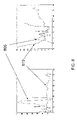
- FIG. 8 illustrates typical row and column sum vectors for a car and a pedestrian in accordance with one embodiment of the present invention.
- the present invention discloses in one embodiment method and apparatus for classifying an object in a region of interest based on one or more features of the object. Detection and classification of pedestrians, vehicles, and other objects are important, e.g., for automotive safety devices, since these devices may deploy in a particular fashion only if a target of the particular type (i.e., pedestrian or car) is about to be impacted. In particular, measures employed to mitigate the injury to a pedestrian may be very different from those employed to mitigate damage and injury from a vehicle-to-vehicle collision.
- FIG. 1 depicts a schematic diagram of a vehicle 100 having a target differentiation system 102 that differentiates a pedestrian (or pedestrians) 110 within a scene 104 that is proximate the vehicle 100 .
- target differentiation system 102 is operable to detect pedestrians, automobiles, or other objects. While in the illustrated embodiment scene 104 is in front of vehicle 100 , other object detection systems may image scenes that are behind or to the side of vehicle 100 .
- target differentiation system 102 need not be related to a vehicle, but can be used with any type of platform, such as a boat, a plane, an elevator, or even stationary streets, docks, or floors.
- Target differentiation system 102 comprises a sensor array 106 that is coupled to an image processor 108 . The sensors within the sensor array 106 have a field of view that includes one or more targets.
- the field of view in a practical object detection system 102 may be ⁇ 12 meters horizontally in front of the vehicle 100 (e.g., approximately 3 traffic lanes), with a ⁇ 3 meter vertical area, and have a view depth of approximately 12-40 meters. Therefore, it should be understood that the present invention can be used in a pedestrian detection system or as part of a collision avoidance system.
- FIG. 2 depicts a block diagram of hardware used to implement the target differentiation system 102 .
- the sensor array 106 comprises, for example, a pair of cameras 200 and 202 .
- an optional secondary sensor 204 can be included.
- the secondary sensor 204 may be radar, a light detection and ranging (LIDAR) sensor, an infrared range finder, a sound navigation and ranging (SONAR) senor, and the like.
- the cameras 200 and 202 generally operate in the visible wavelengths, but may be augmented with infrared sensors, or the cameras may themselves operate in the infrared range.
- the cameras have a known, fixed relation to one another such that they can produce a stereo image of the scene 104 . Therefore, the cameras 200 and 202 will sometimes be referred to herein as stereo cameras.
- the image processor 108 comprises an image preprocessor 206 , a central processing unit (CPU) 210 , support circuits 208 , and memory 212 .
- the image preprocessor 206 generally comprises circuitry for capturing, digitizing and processing the imagery from the sensor array 106 .
- the image preprocessor may be a single chip video processor such as the processor manufactured under the model Acadia ITM by Pyramid Vision Technologies of Princeton, N.J.
- the processed images from the image preprocessor 206 are coupled to the CPU 210 .
- the CPU 210 may comprise any one of a number of presently available high speed microcontrollers or microprocessors.
- CPU 210 is supported by support circuits 208 that are generally well known in the art. These circuits include cache, power supplies, clock circuits, input-output circuitry, and the like.
- Memory 212 is also coupled to CPU 210 .
- Memory 212 stores certain software routines that are retrieved from a storage medium, e.g., an optical disk, and the like, and that are executed by CPU 210 to facilitate operation of the present invention.
- Memory 212 also stores certain databases 214 of information that are used by the present invention, and image processing software 216 that is used to process the imagery from the sensor array 106 .
- the present invention is described in the context of a series of method steps, the method may be performed in hardware, software, or some combination of hardware and software (e.g., an ASIC). Additionally, the methods as disclosed can
- FIG. 3 is a functional block diagram of modules that are used to implement the present invention.
- the stereo cameras 200 and 202 provide stereo imagery to a stereo image preprocessor 300 .
- the stereo image preprocessor is coupled to a depth map generator 302 which is coupled to a target processor 304 .
- Depth map generator 302 may be utilized to define a region of interest (ROI), i.e., an area of the image that potentially contains a target 110 . In some applications the depth map generator 302 is not used. In applications where depth map generator 302 is not used, ROIs would be determined using image-based methods. The following will describe the functional block diagrams under the assumption that a depth map generator 302 is used.
- ROI region of interest
- the target processor 304 receives information from a target template database 306 and from the optional secondary sensor 204 .
- the stereo image preprocessor 300 calibrates the stereo cameras, captures and digitizes imagery, warps the images into alignment, performs pyramid wavelet decomposition, and performs stereo matching, which is generally well known in the art, to create disparity images at different resolutions.
- disparity images having different resolutions are beneficial when detecting objects.
- Calibration provides for a reference point and direction from which all distances and angles are determined.
- Each of the disparity images contains the point-wise motion from the left image to the right image and each corresponds to a different image resolution. The greater the computed disparity of an imaged object, the closer the object is to the sensor array.
- the depth map generator 302 processes the multi-resolution disparity images into a two-dimensional depth image.
- the depth image (also referred to as a depth map) contains image points or pixels in a two dimensional array, where each point represents a specific distance from the sensor array to point within the scene.
- the depth image is then processed by the target processor 304 wherein templates (models) of typical objects encountered by the vision system are compared to the information within the depth image.
- the template database 306 comprises templates of objects (e.g., automobiles, pedestrians) located at various positions and depth with respect to the sensor array.
- An exhaustive search of the template database may be performed to identify a template that most closely matches the present depth image.
- the secondary sensor 204 may provide additional information regarding the position of the object relative to the vehicle, velocity of the object, size or angular width of the object, etc., such that the target template search process can be limited to templates of objects at about the known position relative to the vehicle. If the secondary sensor is a radar sensor, the sensor can, for example, provide an estimate of both object position and distance.
- the target processor 304 produces a target list that is then used to identify target size and classification estimates that enable target tracking and the identification of each target's position, classification and velocity within the scene. That information may then be used to avoid collisions with each target or perform pre-crash alterations to the vehicle to mitigate or eliminate damage (e.g., lower or raise the vehicle, deploy air bags, and the like).
- FIG. 4 depicts a flow diagram of a method 400 for classifying an object in an image.
- the method 400 begins at step 405 and proceeds to step 410 .
- edge energy information and/or intensity variation information is generated for an object in a region of interest (ROI).
- ROI region of interest
- the present invention describes the use of a depth based method to find a ROI where a target 110 may be located, however, ROIs may also be determined using image based methods.
- object(s) occupying the ROI are classified based on edge energy and/or intensity variation information of the target.
- object(s) occupying the ROI are classified based on at least one of edge energy information and intensity variation information. Once edge energy information and/or intensity variation information is found, other information related to the edge energy and/or intensity variation located in the ROI may be found and utilized in making a classification.
- the object is classified based on horizontal edge energy.
- the object is classified based on vertical edge energy.
- Most pedestrians have two strong vertical edges.
- a variation on vertical edge energy is paired edge energy, i.e., a combination of the scores of two edges at expected distances from each other, representing the left and right visible edges of the pedestrian.
- Vehicles may also have vertical edge energy as well, although the ratio of vertical edge and horizontal edge energy would be expected to be higher for pedestrians than vehicles.
- the object is classified based on intensity variation or maximum contrast (one measure of which might be standard deviation).
- intensity variation or maximum contrast one measure of which might be standard deviation.
- the object is classified based on symmetry.
- symmetry For example, most vehicles are symmetrical in many ways about the rear center of the vehicle (whether a license plate is present or not). This symmetry may be measured in terms of pixel intensities, or other higher-level measures such as texture or edge energies.
- the object is classified based on its shadow.
- Vehicles may be detected by its shadow beneath it, particularly on sunny days, where a pedestrian would not have this shadow.
- the width of a pedestrian is determined. Since, pedestrians are significantly thinner than most vehicles, a pedestrian's width may be measured by detecting the underlying asphalt beneath and behind a walking person. For example, windowed regions surrounding a default pedestrian width may be measured for asphalt-like qualities, such as intensity or low texture, whereas the center region (the hypothesized pedestrian) would not have these asphalt-like qualities. This method can be particularly useful in the image space since standard stereo depth image methods often over-estimate the size of the target, due to the windowing effects of the method used.
- the object is classified based on its “parts”.
- a dedicated head and shoulders detector may be able to discriminate pedestrians from other targets, particularly at the closer ranges.
- the 2-D outline of a human figure may be tessellated into regions which are expected to contain human body parts such as a head, shoulders, arms, torso, etc., and region outside these parts (such as above a shoulder and beside the head) would be expected to be background, such as the asphalt behind and beneath the pedestrian.
- Measures which distinguish the two can then be applied to generate a strong pedestrian-detection filter.
- the object is classified based on a histogram of pixel intensity values in a region of interest of the image. This embodiment is explained in more detail in FIG. 5 .
- Each of the above embodiments (e.g., edge energy information or intensity variation information) is considered a “feature”.
- the indicative features may be used in several ways to differentiate pedestrians from vehicles.
- One method is to combine each feature as a conjunction of tests, setting each individual test's thresholds such that any pedestrian (or vehicle) will be expected to pass each test. However, a non-pedestrian would be expected to fail at least one of these tests, despite the particular threshold settings.
- Another method is to require that a pedestrian or vehicle classification pass some threshold subset number of these tests. For example, a pedestrian classification may be required to pass 5 out of 7 possible pedestrian-defining tests.
- Another method is to award points for each test passed, depending on the discriminatory power of each test. A given classification would be required to exceed a certain threshold of points. (Note that the previous method may be regarded as a specific case of this method where each test has equal value.)
- FIG. 5 depicts a flow diagram of a method 500 of classifying an object in an image.
- the method 500 begins at step 505 and proceeds to step 510 .
- step 510 a histogram of pixel intensity values in a region of interest is built.
- the present invention uses a signal processing approach where the histogram is smoothed by convolving the histogram with an averaging filter, and then applying a filter called the “mean-shift” filter to locate the local maxima and minima.
- maxima and minima are located in the histogram. Once all peaks (maxima) and valleys (minima) have been located, the intensity values that define interesting contiguous regions (segments) in the image are identified. The intensity values can be thought of as image contours that segment the image into different regions based on similar intensity values.
- contour scores are assigned to each pixel intensity value.
- Intensity values (contours) are chosen for the final segmentation by assigning a numeric score to each candidate intensity value (or histogram bin).
- each valley as located by the mean-shift filtering of the image histogram (as mentioned above), and the two adjacent peaks on either side of this valley, is considered.
- contour_score ( y 1 ⁇ y 2)+( y 3 ⁇ y 2)+abs(( x 2 ⁇ x 1) ⁇ ( x 3 ⁇ x 2))/( x 3 ⁇ x 1)
- the two peaks are parameterized by (x 1 , y 1 ) and (x 3 , y 3 ), with x 1 referring to the intensity bin value and y 1 referring to the number of image pixel counts in bin x 1 .
- the valley is represented by (x 2 , y 2 ) in the above formula.
- the basic idea is to evaluate how well a valley divides two regions which have peaks (local maxima) in them.
- the relative heights of the peaks and the relative spacing between the peaks and valleys in terms of intensity values affect the score.
- a list of valleys or local minima and their associated scores using the above formula is provided.
- FIG. 6 illustrates an example of a histogram having maxima and minima.
- the result of smoothing 605 and mean-shift filtering 610 on the image histogram is shown.
- Pulse-like feature 620 shows peaks and step-like feature 615 shows valleys.
- the evaluated contours scores (Y-axis) for the valleys (X-axis) are shown with crosses and the best three contour choices are shown with circles.
- the ROI is segmented using two of the contour scores to produce a binary image.
- the following method is utilized. First, the case where at least two valleys (three peaks) are provided is considered. The valleys are rank ordered according to the contour score as described above. From the sorted list, the top two candidates are picked with some additional heuristics to avoid saturated regions. For example, saturated regions would be avoided when, given an image with intensity levels between 0 and 256, if there are candidate valleys with high scores but with intensity values within a small margin of 0 or 256, those candidate valleys would be discarded from a list of probable choices.
- the image is then segmented by thresholding the intensity values between the two chosen contours to generate a binary image. Finally the rows and columns of the binary image are summed (separately) to generate the “row sum” and “column sum” vectors. Then these projected sums are used to generate a measure for object classification for cars and pedestrians.
- FIG. 7 illustrates an example of a segmented region of interest.
- the left image shows a typical image ROI having a car.
- the right image shows the corresponding segmented image using a threshold based the contour scores.
- an object score is determined using the binary image.
- the values for the tuning parameters are adjustable in accordance with application specific requirements.
- FIG. 8 illustrates typical row 805 and column 810 sum vectors for a car (left) and a pedestrian (right).
- the important observation here is the presence of high variations in the row sum as compared to the column sum for the car image.
- the presence of these high variations in the row sum illustrates that the contiguous segments in an image ROI with a car comprise horizontal sections. This appears to be the case for the majority of the cases when a car is in the image.
- the object is classified in accordance with a threshold for the object score.
- the object score from the histogram based segmentation method can be used for classification as follows:
- the present invention allows the score to be offset by a large constant so that the higher level classification algorithm knows that the score is low confidence. This would occur in the case where the image contrast is low or the size of target ROI is small.
- the present invention provides an option to check symmetries along both horizontal and vertical directions and penalize the object score accordingly. This would be useful in the case where a lot of background is included in the image ROI, in addition to the above cases.
- the present invention allows for the employment of additional heuristics to narrow the choice of candidate contours. These techniques are useful in cases where there are a lot of candidate contours for segmenting the ROI.
Abstract
Description
contour_score=(y1−y2)+(y3−y2)+abs((x2−x1)−(x3−x2))/(x3−x1)
object_score=0.1*(alpha*(w/md — y)+beta*(md — x/h))
where md_y equals a mean deviation of the row sum vector; md_x equals a mean deviation of the column sum vector; h is a height of the ROI; w is a width of the ROI; and the tuning parameters, e.g., are alpha=⅓ and beta=⅖. The values for the tuning parameters are adjustable in accordance with application specific requirements.
object_score=0.5*(alpha*(h —1/w —1)+beta*(
where
- h—1=(max(row_sum)−min(row_sum));
-
h —2=(max(column_sum)−min(column_sum)); - w—1=length(row_sum);
-
w —2=length(column_sum); and
tuning parameters are alpha=⅓ and beta=⅖ (Tuning parameters are adjustable in accordance with application specific requirements.)
| 0.25 <= object_score < 0.5 | Pedestrian | ||
| 0.9 > object_score >= 0.5 | Unknown | ||
| car_score >= 0.9 | Car | ||
Claims (12)
Priority Applications (1)
| Application Number | Priority Date | Filing Date | Title |
|---|---|---|---|
| US10/930,735 US7403659B2 (en) | 2003-08-28 | 2004-08-30 | Method and apparatus for differentiating pedestrians, vehicles, and other objects |
Applications Claiming Priority (3)
| Application Number | Priority Date | Filing Date | Title |
|---|---|---|---|
| US49843703P | 2003-08-28 | 2003-08-28 | |
| US54920304P | 2004-03-02 | 2004-03-02 | |
| US10/930,735 US7403659B2 (en) | 2003-08-28 | 2004-08-30 | Method and apparatus for differentiating pedestrians, vehicles, and other objects |
Publications (2)
| Publication Number | Publication Date |
|---|---|
| US20050084156A1 US20050084156A1 (en) | 2005-04-21 |
| US7403659B2 true US7403659B2 (en) | 2008-07-22 |
Family
ID=34278597
Family Applications (1)
| Application Number | Title | Priority Date | Filing Date |
|---|---|---|---|
| US10/930,735 Active 2026-10-04 US7403659B2 (en) | 2003-08-28 | 2004-08-30 | Method and apparatus for differentiating pedestrians, vehicles, and other objects |
Country Status (2)
| Country | Link |
|---|---|
| US (1) | US7403659B2 (en) |
| WO (1) | WO2005022077A2 (en) |
Cited By (19)
| Publication number | Priority date | Publication date | Assignee | Title |
|---|---|---|---|---|
| US20080159620A1 (en) * | 2003-06-13 | 2008-07-03 | Theodore Armand Camus | Vehicular Vision System |
| US20100321513A1 (en) * | 2009-06-17 | 2010-12-23 | Sony Corporation | Content adaptive detection of images with stand-out object |
| US20110071761A1 (en) * | 2009-09-18 | 2011-03-24 | Charles Arnold Cummings | Holistic cybernetic vehicle control |
| US8509523B2 (en) | 2004-07-26 | 2013-08-13 | Tk Holdings, Inc. | Method of identifying an object in a visual scene |
| US20130207833A1 (en) * | 2012-02-13 | 2013-08-15 | Mazda Motor Corporation | Vechicle-mounted radar apparatus |
| US20130335259A1 (en) * | 2011-03-10 | 2013-12-19 | Panasonic Corporation | Object detection device and object detection method |
| US20140002650A1 (en) * | 2012-06-28 | 2014-01-02 | GM Global Technology Operations LLC | Wide baseline binocular object matching method using minimal cost flow network |
| US8768007B2 (en) | 2012-03-26 | 2014-07-01 | Tk Holdings Inc. | Method of filtering an image |
| US8818042B2 (en) | 2004-04-15 | 2014-08-26 | Magna Electronics Inc. | Driver assistance system for vehicle |
| US8824733B2 (en) | 2012-03-26 | 2014-09-02 | Tk Holdings Inc. | Range-cued object segmentation system and method |
| US8842176B2 (en) | 1996-05-22 | 2014-09-23 | Donnelly Corporation | Automatic vehicle exterior light control |
| US8917169B2 (en) | 1993-02-26 | 2014-12-23 | Magna Electronics Inc. | Vehicular vision system |
| US8993951B2 (en) | 1996-03-25 | 2015-03-31 | Magna Electronics Inc. | Driver assistance system for a vehicle |
| US9171217B2 (en) | 2002-05-03 | 2015-10-27 | Magna Electronics Inc. | Vision system for vehicle |
| US9349058B2 (en) | 2012-10-31 | 2016-05-24 | Tk Holdings, Inc. | Vehicular path sensing system and method |
| US9436880B2 (en) | 1999-08-12 | 2016-09-06 | Magna Electronics Inc. | Vehicle vision system |
| US9440535B2 (en) | 2006-08-11 | 2016-09-13 | Magna Electronics Inc. | Vision system for vehicle |
| US10083361B2 (en) | 2013-03-15 | 2018-09-25 | Joyson Safety Systems Acquisition Llc | Path sensing using structured lighting |
| US11148663B2 (en) | 2019-10-02 | 2021-10-19 | Ford Global Technologies, Llc | Enhanced collision mitigation |
Families Citing this family (23)
| Publication number | Priority date | Publication date | Assignee | Title |
|---|---|---|---|---|
| JP4094604B2 (en) * | 2004-11-30 | 2008-06-04 | 本田技研工業株式会社 | Vehicle periphery monitoring device |
| JP4766302B2 (en) * | 2005-03-22 | 2011-09-07 | オムロン株式会社 | Image processing apparatus and method, recording medium, and program |
| US8311730B2 (en) * | 2006-11-29 | 2012-11-13 | Neff Ryan A | Vehicle position determination system |
| US8027029B2 (en) * | 2007-11-07 | 2011-09-27 | Magna Electronics Inc. | Object detection and tracking system |
| US8023741B2 (en) * | 2008-05-23 | 2011-09-20 | Sharp Laboratories Of America, Inc. | Methods and systems for detecting numerals in a digital image |
| US8023770B2 (en) * | 2008-05-23 | 2011-09-20 | Sharp Laboratories Of America, Inc. | Methods and systems for identifying the orientation of a digital image |
| CN101996401B (en) * | 2009-08-24 | 2016-05-11 | 三星电子株式会社 | Target analysis method and apparatus based on intensity image and depth image |
| US8744168B2 (en) * | 2009-08-24 | 2014-06-03 | Samsung Electronics Co., Ltd. | Target analysis apparatus, method and computer-readable medium |
| US8355822B2 (en) * | 2009-12-29 | 2013-01-15 | Masco Corporation Of Indiana | Method of controlling a valve |
| US8408517B2 (en) * | 2009-12-29 | 2013-04-02 | Masco Corporation Of Indiana | Water delivery device |
| US8614414B2 (en) * | 2009-12-29 | 2013-12-24 | Masco Corporation Of Indiana | Proximity sensor |
| JP5861396B2 (en) * | 2011-11-02 | 2016-02-16 | トヨタ自動車株式会社 | Pedestrian detection device for vehicle, pedestrian protection system for vehicle |
| TWI462031B (en) * | 2011-11-10 | 2014-11-21 | Nat Inst Chung Shan Science & Technology | Image pedestrian detection device |
| WO2013106418A1 (en) * | 2012-01-09 | 2013-07-18 | Tk Holdings, Inc. | Stereo-vision object detection system and method |
| US9042908B2 (en) * | 2012-05-08 | 2015-05-26 | International Business Machines Corporation | Identifying purpose-based origin-destination using call detailed records |
| US9076034B2 (en) * | 2012-12-07 | 2015-07-07 | Analog Devices, Inc. | Object localization using vertical symmetry |
| JP6169366B2 (en) * | 2013-02-08 | 2017-07-26 | 株式会社メガチップス | Object detection device, program, and integrated circuit |
| US9669833B2 (en) * | 2015-07-21 | 2017-06-06 | GM Global Technology Operations LLC | Method and system for operating adaptive cruise control system |
| US20170032676A1 (en) * | 2015-07-30 | 2017-02-02 | Illinois Institute Of Technology | System for detecting pedestrians by fusing color and depth information |
| US10212408B1 (en) | 2016-06-29 | 2019-02-19 | Amazon Technologies, Inc. | Depth-map augmentation techniques |
| US10237530B1 (en) * | 2016-06-29 | 2019-03-19 | Amazon Technologies, Inc. | Depth-map augmentation techniques |
| KR101934731B1 (en) * | 2016-11-22 | 2019-01-03 | 엘지전자 주식회사 | Communication device for vehicle and vehicle |
| EP3336800B1 (en) * | 2016-12-19 | 2019-08-28 | Siemens Healthcare GmbH | Determination of a training function for generating annotated training images |
Citations (4)
| Publication number | Priority date | Publication date | Assignee | Title |
|---|---|---|---|---|
| US4783829A (en) * | 1983-02-23 | 1988-11-08 | Hitachi, Ltd. | Pattern recognition apparatus |
| US5487116A (en) * | 1993-05-25 | 1996-01-23 | Matsushita Electric Industrial Co., Ltd. | Vehicle recognition apparatus |
| US5761326A (en) * | 1993-12-08 | 1998-06-02 | Minnesota Mining And Manufacturing Company | Method and apparatus for machine vision classification and tracking |
| US6208749B1 (en) | 1997-02-28 | 2001-03-27 | Electro-Optical Sciences, Inc. | Systems and methods for the multispectral imaging and characterization of skin tissue |
-
2004
- 2004-08-30 WO PCT/US2004/028391 patent/WO2005022077A2/en active Application Filing
- 2004-08-30 US US10/930,735 patent/US7403659B2/en active Active
Patent Citations (4)
| Publication number | Priority date | Publication date | Assignee | Title |
|---|---|---|---|---|
| US4783829A (en) * | 1983-02-23 | 1988-11-08 | Hitachi, Ltd. | Pattern recognition apparatus |
| US5487116A (en) * | 1993-05-25 | 1996-01-23 | Matsushita Electric Industrial Co., Ltd. | Vehicle recognition apparatus |
| US5761326A (en) * | 1993-12-08 | 1998-06-02 | Minnesota Mining And Manufacturing Company | Method and apparatus for machine vision classification and tracking |
| US6208749B1 (en) | 1997-02-28 | 2001-03-27 | Electro-Optical Sciences, Inc. | Systems and methods for the multispectral imaging and characterization of skin tissue |
Cited By (53)
| Publication number | Priority date | Publication date | Assignee | Title |
|---|---|---|---|---|
| US8917169B2 (en) | 1993-02-26 | 2014-12-23 | Magna Electronics Inc. | Vehicular vision system |
| US8993951B2 (en) | 1996-03-25 | 2015-03-31 | Magna Electronics Inc. | Driver assistance system for a vehicle |
| US8842176B2 (en) | 1996-05-22 | 2014-09-23 | Donnelly Corporation | Automatic vehicle exterior light control |
| US9436880B2 (en) | 1999-08-12 | 2016-09-06 | Magna Electronics Inc. | Vehicle vision system |
| US9834216B2 (en) | 2002-05-03 | 2017-12-05 | Magna Electronics Inc. | Vehicular control system using cameras and radar sensor |
| US10118618B2 (en) | 2002-05-03 | 2018-11-06 | Magna Electronics Inc. | Vehicular control system using cameras and radar sensor |
| US10351135B2 (en) | 2002-05-03 | 2019-07-16 | Magna Electronics Inc. | Vehicular control system using cameras and radar sensor |
| US9643605B2 (en) | 2002-05-03 | 2017-05-09 | Magna Electronics Inc. | Vision system for vehicle |
| US9555803B2 (en) | 2002-05-03 | 2017-01-31 | Magna Electronics Inc. | Driver assistance system for vehicle |
| US9171217B2 (en) | 2002-05-03 | 2015-10-27 | Magna Electronics Inc. | Vision system for vehicle |
| US10683008B2 (en) | 2002-05-03 | 2020-06-16 | Magna Electronics Inc. | Vehicular driving assist system using forward-viewing camera |
| US11203340B2 (en) | 2002-05-03 | 2021-12-21 | Magna Electronics Inc. | Vehicular vision system using side-viewing camera |
| US7974442B2 (en) * | 2003-06-13 | 2011-07-05 | Sri International | Vehicular vision system |
| US20080159620A1 (en) * | 2003-06-13 | 2008-07-03 | Theodore Armand Camus | Vehicular Vision System |
| US8818042B2 (en) | 2004-04-15 | 2014-08-26 | Magna Electronics Inc. | Driver assistance system for vehicle |
| US10015452B1 (en) | 2004-04-15 | 2018-07-03 | Magna Electronics Inc. | Vehicular control system |
| US11847836B2 (en) | 2004-04-15 | 2023-12-19 | Magna Electronics Inc. | Vehicular control system with road curvature determination |
| US11503253B2 (en) | 2004-04-15 | 2022-11-15 | Magna Electronics Inc. | Vehicular control system with traffic lane detection |
| US9008369B2 (en) | 2004-04-15 | 2015-04-14 | Magna Electronics Inc. | Vision system for vehicle |
| US10735695B2 (en) | 2004-04-15 | 2020-08-04 | Magna Electronics Inc. | Vehicular control system with traffic lane detection |
| US10462426B2 (en) | 2004-04-15 | 2019-10-29 | Magna Electronics Inc. | Vehicular control system |
| US9191634B2 (en) | 2004-04-15 | 2015-11-17 | Magna Electronics Inc. | Vision system for vehicle |
| US10306190B1 (en) | 2004-04-15 | 2019-05-28 | Magna Electronics Inc. | Vehicular control system |
| US10187615B1 (en) | 2004-04-15 | 2019-01-22 | Magna Electronics Inc. | Vehicular control system |
| US9428192B2 (en) | 2004-04-15 | 2016-08-30 | Magna Electronics Inc. | Vision system for vehicle |
| US10110860B1 (en) | 2004-04-15 | 2018-10-23 | Magna Electronics Inc. | Vehicular control system |
| US9948904B2 (en) | 2004-04-15 | 2018-04-17 | Magna Electronics Inc. | Vision system for vehicle |
| US9736435B2 (en) | 2004-04-15 | 2017-08-15 | Magna Electronics Inc. | Vision system for vehicle |
| US9609289B2 (en) | 2004-04-15 | 2017-03-28 | Magna Electronics Inc. | Vision system for vehicle |
| US8509523B2 (en) | 2004-07-26 | 2013-08-13 | Tk Holdings, Inc. | Method of identifying an object in a visual scene |
| US8594370B2 (en) | 2004-07-26 | 2013-11-26 | Automotive Systems Laboratory, Inc. | Vulnerable road user protection system |
| US11951900B2 (en) | 2006-08-11 | 2024-04-09 | Magna Electronics Inc. | Vehicular forward viewing image capture system |
| US11623559B2 (en) | 2006-08-11 | 2023-04-11 | Magna Electronics Inc. | Vehicular forward viewing image capture system |
| US9440535B2 (en) | 2006-08-11 | 2016-09-13 | Magna Electronics Inc. | Vision system for vehicle |
| US11396257B2 (en) | 2006-08-11 | 2022-07-26 | Magna Electronics Inc. | Vehicular forward viewing image capture system |
| US10071676B2 (en) | 2006-08-11 | 2018-09-11 | Magna Electronics Inc. | Vision system for vehicle |
| US11148583B2 (en) | 2006-08-11 | 2021-10-19 | Magna Electronics Inc. | Vehicular forward viewing image capture system |
| US10787116B2 (en) | 2006-08-11 | 2020-09-29 | Magna Electronics Inc. | Adaptive forward lighting system for vehicle comprising a control that adjusts the headlamp beam in response to processing of image data captured by a camera |
| US8175335B2 (en) | 2009-06-17 | 2012-05-08 | Sony Corporation | Content adaptive detection of images with stand-out object |
| US20100321513A1 (en) * | 2009-06-17 | 2010-12-23 | Sony Corporation | Content adaptive detection of images with stand-out object |
| US8731815B2 (en) | 2009-09-18 | 2014-05-20 | Charles Arnold Cummings | Holistic cybernetic vehicle control |
| US20110071761A1 (en) * | 2009-09-18 | 2011-03-24 | Charles Arnold Cummings | Holistic cybernetic vehicle control |
| US9041588B2 (en) * | 2011-03-10 | 2015-05-26 | Panasonic Intellectual Property Management Co., Ltd. | Object detection device and object detection method |
| US20130335259A1 (en) * | 2011-03-10 | 2013-12-19 | Panasonic Corporation | Object detection device and object detection method |
| US20130207833A1 (en) * | 2012-02-13 | 2013-08-15 | Mazda Motor Corporation | Vechicle-mounted radar apparatus |
| US8976058B2 (en) * | 2012-02-13 | 2015-03-10 | Denso Corporation | Vechicle-mounted radar apparatus |
| US8824733B2 (en) | 2012-03-26 | 2014-09-02 | Tk Holdings Inc. | Range-cued object segmentation system and method |
| US8768007B2 (en) | 2012-03-26 | 2014-07-01 | Tk Holdings Inc. | Method of filtering an image |
| US9228833B2 (en) * | 2012-06-28 | 2016-01-05 | GM Global Technology Operations LLC | Wide baseline binocular object matching method using minimal cost flow network |
| US20140002650A1 (en) * | 2012-06-28 | 2014-01-02 | GM Global Technology Operations LLC | Wide baseline binocular object matching method using minimal cost flow network |
| US9349058B2 (en) | 2012-10-31 | 2016-05-24 | Tk Holdings, Inc. | Vehicular path sensing system and method |
| US10083361B2 (en) | 2013-03-15 | 2018-09-25 | Joyson Safety Systems Acquisition Llc | Path sensing using structured lighting |
| US11148663B2 (en) | 2019-10-02 | 2021-10-19 | Ford Global Technologies, Llc | Enhanced collision mitigation |
Also Published As
| Publication number | Publication date |
|---|---|
| WO2005022077A3 (en) | 2005-06-09 |
| US20050084156A1 (en) | 2005-04-21 |
| WO2005022077A2 (en) | 2005-03-10 |
Similar Documents
| Publication | Publication Date | Title |
|---|---|---|
| US7403659B2 (en) | Method and apparatus for differentiating pedestrians, vehicles, and other objects | |
| US7672514B2 (en) | Method and apparatus for differentiating pedestrians, vehicles, and other objects | |
| US7103213B2 (en) | Method and apparatus for classifying an object | |
| EP3229041B1 (en) | Object detection using radar and vision defined image detection zone | |
| US7466860B2 (en) | Method and apparatus for classifying an object | |
| US20050232463A1 (en) | Method and apparatus for detecting a presence prior to collision | |
| US7660436B2 (en) | Stereo-vision based imminent collision detection | |
| US7697786B2 (en) | Method and apparatus for detecting edges of an object | |
| US6956469B2 (en) | Method and apparatus for pedestrian detection | |
| US7486803B2 (en) | Method and apparatus for object tracking prior to imminent collision detection | |
| Nedevschi et al. | High accuracy stereovision approach for obstacle detection on non-planar roads | |
| US20040057599A1 (en) | Image processing apparatus and method | |
| US7321669B2 (en) | Method and apparatus for refining target position and size estimates using image and depth data | |
| Kamijo et al. | Pedestrian detection algorithm for on-board cameras of multi view angles | |
| Chang et al. | Stereo-based object detection, classi? cation, and quantitative evaluation with automotive applications | |
| Ma et al. | A real time object detection approach applied to reliable pedestrian detection | |
| Keller et al. | Dense stereo-based roi generation for pedestrian detection | |
| KR101478072B1 (en) | Method for Detecting Vehicle | |
| Lin et al. | Incorporating appearance and edge features for vehicle detection in the blind-spot area | |
| Dang et al. | Fast object hypotheses generation using 3D position and 3D motion | |
| Hwang et al. | Vehicle detection system design based on stereo vision sensors | |
| Alvarez et al. | Vehicle and pedestrian detection in esafety applications | |
| Lin et al. | Pedestrians and vehicles recognition based on image recognition and laser distance detection | |
| Seo et al. | Compound road environment recognition method using camera and laser range finder | |
| Yang et al. | Pedestrian detection on moving vehicle using stereovision and 2d cue |
Legal Events
| Date | Code | Title | Description |
|---|---|---|---|
| AS | Assignment |
Owner name: SARNOFF CORPORATION, NEW JERSEY Free format text: ASSIGNMENT OF ASSIGNORS INTEREST;ASSIGNORS:DAS, AVEEK KUMAR;CAMUS, THEODORE ARMAND;CHANG, PENG;REEL/FRAME:016086/0323;SIGNING DATES FROM 20041210 TO 20041214 |
|
| STCF | Information on status: patent grant |
Free format text: PATENTED CASE |
|
| FPAY | Fee payment |
Year of fee payment: 4 |
|
| AS | Assignment |
Owner name: SRI INTERNATIONAL, CALIFORNIA Free format text: MERGER;ASSIGNOR:SARNOFF CORPORATION;REEL/FRAME:036264/0390 Effective date: 20110204 |
|
| FPAY | Fee payment |
Year of fee payment: 8 |
|
| MAFP | Maintenance fee payment |
Free format text: PAYMENT OF MAINTENANCE FEE, 12TH YEAR, LARGE ENTITY (ORIGINAL EVENT CODE: M1553); ENTITY STATUS OF PATENT OWNER: LARGE ENTITY Year of fee payment: 12 |
|
| AS | Assignment |
Owner name: IP3 2019, SERIES 400 OF ALLIED SECURITY TRUST I, C Free format text: ASSIGNMENT OF ASSIGNORS INTEREST;ASSIGNOR:SRI INTERNATIONAL;REEL/FRAME:051355/0223 Effective date: 20191121 |
|
| AS | Assignment |
Owner name: ZAMA INNOVATIONS LLC, DELAWARE Free format text: ASSIGNMENT OF ASSIGNORS INTEREST;ASSIGNOR:IP3 2019, SERIES 400 OF ALLIED SECURITY TRUST I;REEL/FRAME:057407/0395 Effective date: 20210825 |