US7410468B2 - Method and apparatus for penetrating tissue - Google Patents
Method and apparatus for penetrating tissue Download PDFInfo
- Publication number
- US7410468B2 US7410468B2 US10/335,182 US33518202A US7410468B2 US 7410468 B2 US7410468 B2 US 7410468B2 US 33518202 A US33518202 A US 33518202A US 7410468 B2 US7410468 B2 US 7410468B2
- Authority
- US
- United States
- Prior art keywords
- penetrating member
- penetrating
- sample chamber
- cartridge
- tissue
- Prior art date
- Legal status (The legal status is an assumption and is not a legal conclusion. Google has not performed a legal analysis and makes no representation as to the accuracy of the status listed.)
- Expired - Fee Related, expires
Links
Images


Classifications
-
- G—PHYSICS
- G01—MEASURING; TESTING
- G01N—INVESTIGATING OR ANALYSING MATERIALS BY DETERMINING THEIR CHEMICAL OR PHYSICAL PROPERTIES
- G01N33/00—Investigating or analysing materials by specific methods not covered by groups G01N1/00 - G01N31/00
- G01N33/48—Biological material, e.g. blood, urine; Haemocytometers
- G01N33/50—Chemical analysis of biological material, e.g. blood, urine; Testing involving biospecific ligand binding methods; Immunological testing
- G01N33/53—Immunoassay; Biospecific binding assay; Materials therefor
- G01N33/557—Immunoassay; Biospecific binding assay; Materials therefor using kinetic measurement, i.e. time rate of progress of an antigen-antibody interaction
-
- A—HUMAN NECESSITIES
- A61—MEDICAL OR VETERINARY SCIENCE; HYGIENE
- A61B—DIAGNOSIS; SURGERY; IDENTIFICATION
- A61B5/00—Measuring for diagnostic purposes; Identification of persons
- A61B5/145—Measuring characteristics of blood in vivo, e.g. gas concentration, pH value; Measuring characteristics of body fluids or tissues, e.g. interstitial fluid, cerebral tissue
- A61B5/14546—Measuring characteristics of blood in vivo, e.g. gas concentration, pH value; Measuring characteristics of body fluids or tissues, e.g. interstitial fluid, cerebral tissue for measuring analytes not otherwise provided for, e.g. ions, cytochromes
-
- A—HUMAN NECESSITIES
- A61—MEDICAL OR VETERINARY SCIENCE; HYGIENE
- A61B—DIAGNOSIS; SURGERY; IDENTIFICATION
- A61B5/00—Measuring for diagnostic purposes; Identification of persons
- A61B5/15—Devices for taking samples of blood
- A61B5/150007—Details
- A61B5/150015—Source of blood
- A61B5/150022—Source of blood for capillary blood or interstitial fluid
-
- A—HUMAN NECESSITIES
- A61—MEDICAL OR VETERINARY SCIENCE; HYGIENE
- A61B—DIAGNOSIS; SURGERY; IDENTIFICATION
- A61B5/00—Measuring for diagnostic purposes; Identification of persons
- A61B5/15—Devices for taking samples of blood
- A61B5/150007—Details
- A61B5/150053—Details for enhanced collection of blood or interstitial fluid at the sample site, e.g. by applying compression, heat, vibration, ultrasound, suction or vacuum to tissue; for reduction of pain or discomfort; Skin piercing elements, e.g. blades, needles, lancets or canulas, with adjustable piercing speed
- A61B5/150106—Means for reducing pain or discomfort applied before puncturing; desensitising the skin at the location where body is to be pierced
- A61B5/150152—Means for reducing pain or discomfort applied before puncturing; desensitising the skin at the location where body is to be pierced by an adequate mechanical impact on the puncturing location
-
- A—HUMAN NECESSITIES
- A61—MEDICAL OR VETERINARY SCIENCE; HYGIENE
- A61B—DIAGNOSIS; SURGERY; IDENTIFICATION
- A61B5/00—Measuring for diagnostic purposes; Identification of persons
- A61B5/15—Devices for taking samples of blood
- A61B5/150007—Details
- A61B5/150053—Details for enhanced collection of blood or interstitial fluid at the sample site, e.g. by applying compression, heat, vibration, ultrasound, suction or vacuum to tissue; for reduction of pain or discomfort; Skin piercing elements, e.g. blades, needles, lancets or canulas, with adjustable piercing speed
- A61B5/150167—Adjustable piercing speed of skin piercing element, e.g. blade, needle, lancet or canula, for example with varying spring force or pneumatic drive
-
- A—HUMAN NECESSITIES
- A61—MEDICAL OR VETERINARY SCIENCE; HYGIENE
- A61B—DIAGNOSIS; SURGERY; IDENTIFICATION
- A61B5/00—Measuring for diagnostic purposes; Identification of persons
- A61B5/15—Devices for taking samples of blood
- A61B5/150007—Details
- A61B5/150175—Adjustment of penetration depth
-
- A—HUMAN NECESSITIES
- A61—MEDICAL OR VETERINARY SCIENCE; HYGIENE
- A61B—DIAGNOSIS; SURGERY; IDENTIFICATION
- A61B5/00—Measuring for diagnostic purposes; Identification of persons
- A61B5/15—Devices for taking samples of blood
- A61B5/150007—Details
- A61B5/150206—Construction or design features not otherwise provided for; manufacturing or production; packages; sterilisation of piercing element, piercing device or sampling device
- A61B5/150221—Valves
-
- A—HUMAN NECESSITIES
- A61—MEDICAL OR VETERINARY SCIENCE; HYGIENE
- A61B—DIAGNOSIS; SURGERY; IDENTIFICATION
- A61B5/00—Measuring for diagnostic purposes; Identification of persons
- A61B5/15—Devices for taking samples of blood
- A61B5/150007—Details
- A61B5/150358—Strips for collecting blood, e.g. absorbent
-
- A—HUMAN NECESSITIES
- A61—MEDICAL OR VETERINARY SCIENCE; HYGIENE
- A61B—DIAGNOSIS; SURGERY; IDENTIFICATION
- A61B5/00—Measuring for diagnostic purposes; Identification of persons
- A61B5/15—Devices for taking samples of blood
- A61B5/150007—Details
- A61B5/150374—Details of piercing elements or protective means for preventing accidental injuries by such piercing elements
- A61B5/150381—Design of piercing elements
- A61B5/150412—Pointed piercing elements, e.g. needles, lancets for piercing the skin
- A61B5/150427—Specific tip design, e.g. for improved penetration characteristics
-
- A—HUMAN NECESSITIES
- A61—MEDICAL OR VETERINARY SCIENCE; HYGIENE
- A61B—DIAGNOSIS; SURGERY; IDENTIFICATION
- A61B5/00—Measuring for diagnostic purposes; Identification of persons
- A61B5/15—Devices for taking samples of blood
- A61B5/150007—Details
- A61B5/150374—Details of piercing elements or protective means for preventing accidental injuries by such piercing elements
- A61B5/150381—Design of piercing elements
- A61B5/150503—Single-ended needles
-
- A—HUMAN NECESSITIES
- A61—MEDICAL OR VETERINARY SCIENCE; HYGIENE
- A61B—DIAGNOSIS; SURGERY; IDENTIFICATION
- A61B5/00—Measuring for diagnostic purposes; Identification of persons
- A61B5/15—Devices for taking samples of blood
- A61B5/150007—Details
- A61B5/150374—Details of piercing elements or protective means for preventing accidental injuries by such piercing elements
- A61B5/150534—Design of protective means for piercing elements for preventing accidental needle sticks, e.g. shields, caps, protectors, axially extensible sleeves, pivotable protective sleeves
- A61B5/150572—Pierceable protectors, e.g. shields, caps, sleeves or films, e.g. for hygienic purposes
-
- A—HUMAN NECESSITIES
- A61—MEDICAL OR VETERINARY SCIENCE; HYGIENE
- A61B—DIAGNOSIS; SURGERY; IDENTIFICATION
- A61B5/00—Measuring for diagnostic purposes; Identification of persons
- A61B5/15—Devices for taking samples of blood
- A61B5/150007—Details
- A61B5/150847—Communication to or from blood sampling device
- A61B5/15087—Communication to or from blood sampling device short range, e.g. between console and disposable
-
- A—HUMAN NECESSITIES
- A61—MEDICAL OR VETERINARY SCIENCE; HYGIENE
- A61B—DIAGNOSIS; SURGERY; IDENTIFICATION
- A61B5/00—Measuring for diagnostic purposes; Identification of persons
- A61B5/15—Devices for taking samples of blood
- A61B5/151—Devices specially adapted for taking samples of capillary blood, e.g. by lancets, needles or blades
- A61B5/15101—Details
- A61B5/15103—Piercing procedure
- A61B5/15107—Piercing being assisted by a triggering mechanism
- A61B5/15113—Manually triggered, i.e. the triggering requires a deliberate action by the user such as pressing a drive button
-
- A—HUMAN NECESSITIES
- A61—MEDICAL OR VETERINARY SCIENCE; HYGIENE
- A61B—DIAGNOSIS; SURGERY; IDENTIFICATION
- A61B5/00—Measuring for diagnostic purposes; Identification of persons
- A61B5/15—Devices for taking samples of blood
- A61B5/151—Devices specially adapted for taking samples of capillary blood, e.g. by lancets, needles or blades
- A61B5/15101—Details
- A61B5/15115—Driving means for propelling the piercing element to pierce the skin, e.g. comprising mechanisms based on shape memory alloys, magnetism, solenoids, piezoelectric effect, biased elements, resilient elements, vacuum or compressed fluids
- A61B5/15123—Driving means for propelling the piercing element to pierce the skin, e.g. comprising mechanisms based on shape memory alloys, magnetism, solenoids, piezoelectric effect, biased elements, resilient elements, vacuum or compressed fluids comprising magnets or solenoids
-
- A—HUMAN NECESSITIES
- A61—MEDICAL OR VETERINARY SCIENCE; HYGIENE
- A61B—DIAGNOSIS; SURGERY; IDENTIFICATION
- A61B5/00—Measuring for diagnostic purposes; Identification of persons
- A61B5/15—Devices for taking samples of blood
- A61B5/151—Devices specially adapted for taking samples of capillary blood, e.g. by lancets, needles or blades
- A61B5/15146—Devices loaded with multiple lancets simultaneously, e.g. for serial firing without reloading, for example by use of stocking means.
- A61B5/15148—Constructional features of stocking means, e.g. strip, roll, disc, cartridge, belt or tube
- A61B5/15149—Arrangement of piercing elements relative to each other
- A61B5/15153—Multiple piercing elements stocked in a single compartment
-
- A—HUMAN NECESSITIES
- A61—MEDICAL OR VETERINARY SCIENCE; HYGIENE
- A61B—DIAGNOSIS; SURGERY; IDENTIFICATION
- A61B5/00—Measuring for diagnostic purposes; Identification of persons
- A61B5/15—Devices for taking samples of blood
- A61B5/151—Devices specially adapted for taking samples of capillary blood, e.g. by lancets, needles or blades
- A61B5/15146—Devices loaded with multiple lancets simultaneously, e.g. for serial firing without reloading, for example by use of stocking means.
- A61B5/15148—Constructional features of stocking means, e.g. strip, roll, disc, cartridge, belt or tube
- A61B5/15157—Geometry of stocking means or arrangement of piercing elements therein
- A61B5/15159—Piercing elements stocked in or on a disc
- A61B5/15163—Characterized by propelling the piercing element in an axial direction relative to the disc
-
- A—HUMAN NECESSITIES
- A61—MEDICAL OR VETERINARY SCIENCE; HYGIENE
- A61B—DIAGNOSIS; SURGERY; IDENTIFICATION
- A61B5/00—Measuring for diagnostic purposes; Identification of persons
- A61B5/15—Devices for taking samples of blood
- A61B5/151—Devices specially adapted for taking samples of capillary blood, e.g. by lancets, needles or blades
- A61B5/15146—Devices loaded with multiple lancets simultaneously, e.g. for serial firing without reloading, for example by use of stocking means.
- A61B5/15148—Constructional features of stocking means, e.g. strip, roll, disc, cartridge, belt or tube
- A61B5/15157—Geometry of stocking means or arrangement of piercing elements therein
- A61B5/15165—Piercing elements stocked in or on a strip
- A61B5/15169—Characterized by a rolled strip
-
- A—HUMAN NECESSITIES
- A61—MEDICAL OR VETERINARY SCIENCE; HYGIENE
- A61B—DIAGNOSIS; SURGERY; IDENTIFICATION
- A61B5/00—Measuring for diagnostic purposes; Identification of persons
- A61B5/15—Devices for taking samples of blood
- A61B5/151—Devices specially adapted for taking samples of capillary blood, e.g. by lancets, needles or blades
- A61B5/15146—Devices loaded with multiple lancets simultaneously, e.g. for serial firing without reloading, for example by use of stocking means.
- A61B5/15148—Constructional features of stocking means, e.g. strip, roll, disc, cartridge, belt or tube
- A61B5/15157—Geometry of stocking means or arrangement of piercing elements therein
- A61B5/15165—Piercing elements stocked in or on a strip
- A61B5/15171—Characterized by propelling the piercing element perpendicular to the direction of movement of the strip
-
- A—HUMAN NECESSITIES
- A61—MEDICAL OR VETERINARY SCIENCE; HYGIENE
- A61B—DIAGNOSIS; SURGERY; IDENTIFICATION
- A61B5/00—Measuring for diagnostic purposes; Identification of persons
- A61B5/15—Devices for taking samples of blood
- A61B5/151—Devices specially adapted for taking samples of capillary blood, e.g. by lancets, needles or blades
- A61B5/15146—Devices loaded with multiple lancets simultaneously, e.g. for serial firing without reloading, for example by use of stocking means.
- A61B5/15148—Constructional features of stocking means, e.g. strip, roll, disc, cartridge, belt or tube
- A61B5/15178—Stocking means comprising separate compartments or units for new and for used piercing elements
-
- A—HUMAN NECESSITIES
- A61—MEDICAL OR VETERINARY SCIENCE; HYGIENE
- A61B—DIAGNOSIS; SURGERY; IDENTIFICATION
- A61B5/00—Measuring for diagnostic purposes; Identification of persons
- A61B5/15—Devices for taking samples of blood
- A61B5/151—Devices specially adapted for taking samples of capillary blood, e.g. by lancets, needles or blades
- A61B5/15146—Devices loaded with multiple lancets simultaneously, e.g. for serial firing without reloading, for example by use of stocking means.
- A61B5/15184—Piercing device comprising a separate compartment or unit for used piercing elements
-
- A—HUMAN NECESSITIES
- A61—MEDICAL OR VETERINARY SCIENCE; HYGIENE
- A61B—DIAGNOSIS; SURGERY; IDENTIFICATION
- A61B5/00—Measuring for diagnostic purposes; Identification of persons
- A61B5/15—Devices for taking samples of blood
- A61B5/151—Devices specially adapted for taking samples of capillary blood, e.g. by lancets, needles or blades
- A61B5/15186—Devices loaded with a single lancet, i.e. a single lancet with or without a casing is loaded into a reusable drive device and then discarded after use; drive devices reloadable for multiple use
-
- A—HUMAN NECESSITIES
- A61—MEDICAL OR VETERINARY SCIENCE; HYGIENE
- A61B—DIAGNOSIS; SURGERY; IDENTIFICATION
- A61B5/00—Measuring for diagnostic purposes; Identification of persons
- A61B5/15—Devices for taking samples of blood
- A61B5/157—Devices characterised by integrated means for measuring characteristics of blood
-
- B—PERFORMING OPERATIONS; TRANSPORTING
- B01—PHYSICAL OR CHEMICAL PROCESSES OR APPARATUS IN GENERAL
- B01L—CHEMICAL OR PHYSICAL LABORATORY APPARATUS FOR GENERAL USE
- B01L3/00—Containers or dishes for laboratory use, e.g. laboratory glassware; Droppers
- B01L3/50—Containers for the purpose of retaining a material to be analysed, e.g. test tubes
- B01L3/502—Containers for the purpose of retaining a material to be analysed, e.g. test tubes with fluid transport, e.g. in multi-compartment structures
- B01L3/5027—Containers for the purpose of retaining a material to be analysed, e.g. test tubes with fluid transport, e.g. in multi-compartment structures by integrated microfluidic structures, i.e. dimensions of channels and chambers are such that surface tension forces are important, e.g. lab-on-a-chip
- B01L3/502715—Containers for the purpose of retaining a material to be analysed, e.g. test tubes with fluid transport, e.g. in multi-compartment structures by integrated microfluidic structures, i.e. dimensions of channels and chambers are such that surface tension forces are important, e.g. lab-on-a-chip characterised by interfacing components, e.g. fluidic, electrical, optical or mechanical interfaces
-
- A—HUMAN NECESSITIES
- A61—MEDICAL OR VETERINARY SCIENCE; HYGIENE
- A61B—DIAGNOSIS; SURGERY; IDENTIFICATION
- A61B17/00—Surgical instruments, devices or methods, e.g. tourniquets
- A61B17/32—Surgical cutting instruments
- A61B17/3209—Incision instruments
- A61B17/32093—Incision instruments for skin incisions
-
- A—HUMAN NECESSITIES
- A61—MEDICAL OR VETERINARY SCIENCE; HYGIENE
- A61B—DIAGNOSIS; SURGERY; IDENTIFICATION
- A61B5/00—Measuring for diagnostic purposes; Identification of persons
- A61B5/145—Measuring characteristics of blood in vivo, e.g. gas concentration, pH value; Measuring characteristics of body fluids or tissues, e.g. interstitial fluid, cerebral tissue
- A61B5/14532—Measuring characteristics of blood in vivo, e.g. gas concentration, pH value; Measuring characteristics of body fluids or tissues, e.g. interstitial fluid, cerebral tissue for measuring glucose, e.g. by tissue impedance measurement
-
- A—HUMAN NECESSITIES
- A61—MEDICAL OR VETERINARY SCIENCE; HYGIENE
- A61M—DEVICES FOR INTRODUCING MEDIA INTO, OR ONTO, THE BODY; DEVICES FOR TRANSDUCING BODY MEDIA OR FOR TAKING MEDIA FROM THE BODY; DEVICES FOR PRODUCING OR ENDING SLEEP OR STUPOR
- A61M5/00—Devices for bringing media into the body in a subcutaneous, intra-vascular or intramuscular way; Accessories therefor, e.g. filling or cleaning devices, arm-rests
- A61M5/002—Packages specially adapted therefor, e.g. for syringes or needles, kits for diabetics
- A61M2005/004—Magazines with multiple needles directly inserted into an injection or infusion device, e.g. revolver-like magazines
-
- B—PERFORMING OPERATIONS; TRANSPORTING
- B01—PHYSICAL OR CHEMICAL PROCESSES OR APPARATUS IN GENERAL
- B01L—CHEMICAL OR PHYSICAL LABORATORY APPARATUS FOR GENERAL USE
- B01L2200/00—Solutions for specific problems relating to chemical or physical laboratory apparatus
- B01L2200/10—Integrating sample preparation and analysis in single entity, e.g. lab-on-a-chip concept
-
- B—PERFORMING OPERATIONS; TRANSPORTING
- B01—PHYSICAL OR CHEMICAL PROCESSES OR APPARATUS IN GENERAL
- B01L—CHEMICAL OR PHYSICAL LABORATORY APPARATUS FOR GENERAL USE
- B01L2300/00—Additional constructional details
- B01L2300/06—Auxiliary integrated devices, integrated components
- B01L2300/0627—Sensor or part of a sensor is integrated
- B01L2300/0663—Whole sensors
-
- B—PERFORMING OPERATIONS; TRANSPORTING
- B01—PHYSICAL OR CHEMICAL PROCESSES OR APPARATUS IN GENERAL
- B01L—CHEMICAL OR PHYSICAL LABORATORY APPARATUS FOR GENERAL USE
- B01L2300/00—Additional constructional details
- B01L2300/18—Means for temperature control
-
- G—PHYSICS
- G01—MEASURING; TESTING
- G01N—INVESTIGATING OR ANALYSING MATERIALS BY DETERMINING THEIR CHEMICAL OR PHYSICAL PROPERTIES
- G01N33/00—Investigating or analysing materials by specific methods not covered by groups G01N1/00 - G01N31/00
- G01N33/48—Biological material, e.g. blood, urine; Haemocytometers
- G01N33/483—Physical analysis of biological material
- G01N33/487—Physical analysis of biological material of liquid biological material
- G01N33/49—Blood
- G01N33/4905—Determining clotting time of blood
Definitions
- Lancing devices are known in the medical health-care products industry for piercing the skin to produce blood for analysis.
- a drop of blood for this type of analysis is obtained by making a small incision in the fingertip, creating a small wound, which generates a small blood droplet on the surface of the skin.
- Another impediment to patient compliance is the lack of spontaneous blood flow generated by known lancing technology.
- a patient may need more than one lancing event to obtain a blood sample since spontaneous blood generation is unreliable using known lancing technology.
- the pain is multiplied by the number of tries it takes to successfully generate spontaneous blood flow.
- Different skin thickness may yield different results in terms of pain perception, blood yield and success rate of obtaining blood between different users of the lancing device.
- Known devices poorly account for these skin thickness variations.
- a still further impediment to improved compliance with glucose monitoring are the many steps and hassle associated with each lancing event.
- Many diabetic patients that are insulin dependent may need to self-test for blood glucose levels five to six times daily.
- the large number of steps required in traditional methods of glucose testing, ranging from lancing, to milking of blood, applying blood to the test strip, and getting the measurements from the test strip discourages many diabetic patients from testing their blood glucose levels as often as recommended.
- Older patients and those with deteriorating motor skills encounter difficulty loading lancets into launcher devices, transferring blood onto a test strip, or inserting thin test strips into slots on glucose measurement meters.
- the wound channel left on the patient by known systems may also be of a size that discourages those who are active with their hands or who are concerned about healing of those wound channels from testing their glucose levels.
- an object of the present invention is to provide improved tissue penetrating systems, and their methods of use.
- Another object of the present invention is to provide tissue penetrating systems, and their methods of use, that provide reduced pain when penetrating a target tissue.
- Yet another object of the present invention is to provide tissue penetrating systems, and their methods of use, that provide controlled depth of penetration.
- Still a further object of the present invention is to provide tissue penetrating systems, and their methods of use, that provide controlled velocities into and out of target tissue.
- a further object of the present invention is to provide tissue penetrating systems, and their methods of use, that provide stimulation to a target tissue.
- Another object of the present invention is to provide tissue penetrating systems, and their methods of use, that apply a pressure to a target tissue.
- Yet another object of the present invention is to provide tissue penetrating systems, and their methods of use, with penetrating members that remain in sterile environments prior to launch.
- Still another object of the present invention is to provide tissue penetrating systems, and their methods of use, with penetrating members that remain in sterile environments prior to launch, and the penetrating members are not used to breach the sterile environment.
- a further object of the present invention is to provide improved tissue penetrating systems, and their methods of use, that have user interfaces.
- Another object of the present invention is to provide improved tissue penetrating systems, and their methods of use, that have human interfaces.
- Yet another object of the present invention is to provide tissue penetrating systems, and their methods of use, that have low volume sample chambers.
- Still another object of the present invention is to provide tissue penetrating systems, and their methods of use, that have sample chambers with volumes that do not exceed 1 ⁇ L.
- Another object of the present invention is to provide tissue penetrating systems, and their methods of use, that have multiple penetrating members housed in a cartridge.
- a skin penetrating system that includes a housing member and a penetrating member positioned in the housing member.
- An analyte detecting member is coupled to a sample chamber.
- the analyte detecting member is configured to determine a concentration of an analyte in a body fluid using a sample of less than 1 ⁇ L of a body fluid disposed in the sample chamber.
- a tip of the penetrating member is configured to extend through an opening of the sample chamber.
- a skin penetrating system in another embodiment, includes a housing member and a plurality of penetrating members positioned in the housing member.
- a plurality of analyte detecting members are each associated with a penetrating member and a sample chamber.
- the analyte detecting member is configured to determine a concentration of an analyte in a body fluid using a sample of less than 1 ⁇ L of a body fluid disposed in the sample chamber.
- a tip of the penetrating member is configured to extend through an opening of a sample chamber.
- a tissue penetrating system in another embodiment, includes a penetrating member driver.
- a cartridge with distal and proximal ports, is coupled to the penetrating member driver.
- An analyte detecting member is coupled to a sample chamber. The analyte detecting member is configured to determine a concentration of an analyte in a body fluid using a sample of less than 1 ⁇ L of a body fluid disposed in the sample chamber.
- a penetrating member has a sharpened distal tip and shaft portion that is slidably disposed within the cartridge. A tip of the penetrating member is configured to extend through the opening of the sample chamber.
- a tissue penetrating system in another embodiment, includes a penetrating member driver.
- a cartridge with distal and proximal ports, is coupled to the penetrating member driver.
- An analyte detecting member is coupled to a sample chamber. The analyte detecting member is configured to determine a concentration of an analyte in a body fluid using a sample of less than 1 ⁇ L of a body fluid disposed in the sample chamber.
- a penetrating member has a sharpened distal tip and a shaft portion that is slidably disposed within the cartridge. A tip of the penetrating member is configured to extend through the opening of the analyte detecting member.
- a first seal is formed at the distal port and a second seal formed at the proximal port.
- the first and second seals maintain the distal tip of the penetrating member, and the sample chamber, in a sterile environment prior to launch of the penetrating member.
- a tissue penetrating system in another embodiment, includes a cartridge with a distal port and a proximal port.
- Each cartridge includes an analyte detecting member coupled to a sample chamber,.
- the analyte detecting member is configured to determine a concentration of an analyte in a body fluid using a sample of less than 1 ⁇ L of a body fluid disposed in the sample chamber.
- a penetrating member has a sharpened distal tip and a shaft portion that is slidably disposed within the cartridge.
- a first seal covers the distal port.
- a second seal covers the proximal port.
- a tissue penetrating system in another embodiment, includes a plurality of penetrating members each having a sharpened distal tip.
- a penetrating member driver is coupled to the plurality of penetrating members.
- a plurality of cartridges each house a penetrating member and are configured so that the penetrating member driver engages each of the penetrating members sequentially.
- Each cartridge includes an analyte detecting member coupled to a sample chamber. The analyte detecting member is configured to determine a concentration of an analyte in a body fluid using a sample of less than 1 ⁇ L of a body fluid disposed in the sample chamber.
- a tissue penetrating system in another embodiment, includes a plurality of cartridges.
- Each cartridge includes an analyte detecting member coupled to a sample chamber.
- the analyte detecting member is configured to determine a concentration of an analyte in a body fluid using a sample of less than 1 ⁇ L of a body fluid disposed in the sample chamber.
- Each of the cartridges has a plurality of seals positioned so that the sample chamber remains in a sterile environment before launch of a penetrating member.
- the plurality of cartridges are coupled together in an array.
- a method of penetrating a target tissue provides a tissue penetrating system with a penetrating member and an analyte detecting member coupled to a sample chamber. A penetrating member is advanced through the target tissue. The penetrating member is withdrawn from the target tissue. No more than 1 ⁇ L of a body fluid is received in the sample chamber.
- a skin penetrating system that includes a housing member.
- a plurality of penetrating members are positioned in the housing member.
- a plurality of analyte detecting members are each associated with a penetrating member.
- Each analyte detecting member includes a sample chamber and an opening for transport of a body fluid into the sample chamber.
- the analyte detecting member is configured to determine a concentration of an analyte in a body fluid using a sample of less than 1 ⁇ L of a body fluid disposed in the sample chamber.
- a user interface is configured to relay at least one of, skin penetrating performance or a skin penetrating setting.
- a skin penetrating system in another embodiment, includes a housing member and a plurality of penetrating members positioned in the housing member.
- a penetrating member driver is coupled to the plurality of penetrating members.
- a plurality of analyte detecting members are each associated with a penetrating member.
- Each analyte detecting member includes a sample chamber and an opening for transport of a body fluid into the sample chamber.
- the analyte detecting member is configured to determine a concentration of an analyte in a body fluid using a sample of less than 1 ⁇ L of a body fluid disposed in the sample chamber.
- a human interface is included and provides at least one output.
- a tissue penetrating system in another embodiment, includes a penetrating member driver.
- a cartridge with distal and proximal ports, is coupled to the penetrating member driver.
- An analyte detecting member is coupled to a sample chamber. The analyte detecting member is configured to determine a concentration of an analyte in a body fluid using a sample of less than 1 ⁇ L of a body fluid disposed in the sample chamber.
- a penetrating member has a sharpened distal tip and a shaft portion that is slidably disposed within the cartridge. A tip of the penetrating member is configured to extend through the opening of the sample chamber.
- a user interface is configured to relay at least one of, skin penetrating performance or a skin penetrating setting.
- a tissue penetrating system in another embodiment, includes a penetrating member driver.
- a cartridge with distal and proximal ports, is coupled to the penetrating member driver.
- An analyte detecting member is coupled to a sample chamber. The analyte detecting member is configured to determine a concentration of an analyte in a body fluid using a sample of less than 1 ⁇ L of a body fluid disposed in the sample chamber.
- a penetrating member has a sharpened distal tip and a shaft portion that is slidably disposed within the cartridge. A tip of the penetrating member is configured to extend through the opening of the sample chamber.
- a human interface is includes and provides at least one output.
- FIG. 1 illustrates an embodiment of a controllable force driver in the form of a cylindrical electric penetrating member driver using a coiled solenoid-type configuration.
- FIG. 2A illustrates a displacement over time profile of a penetrating member driven by a harmonic spring/mass system.
- FIG. 2B illustrates the velocity over time profile of a penetrating member driver by a harmonic spring/mass system.
- FIG. 2C illustrates a displacement over time profile of an embodiment of a controllable force driver.
- FIG. 2D illustrates a velocity over time profile of an embodiment of a controllable force driver.
- FIG. 3 is a diagrammatic view illustrating a controlled feed-back loop.
- FIG. 4 is a perspective view of a tissue penetration device having features of the invention.
- FIG. 5 is an elevation view in partial longitudinal section of the tissue penetration device of FIG. 4 .
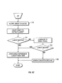
- FIGS. 6A-6C show a flowchart illustrating a penetrating member control method.
- FIG. 7 is a diagrammatic view of a patient's finger and a penetrating member tip moving toward the skin of the finger.
- FIG. 8 is a diagrammatic view of a patient's finger and the penetrating member tip making contact with the skin of a patient's finger.
- FIG. 9 is a diagrammatic view of the penetrating member tip depressing the skin of a patient's finger.
- FIG. 10 is a diagrammatic view of the penetrating member tip further depressing the skin of a patient's finger.
- FIG. 11 is a diagrammatic view of the penetrating member tip penetrating the skin of a patient's finger.
- FIG. 12 is a diagrammatic view of the penetrating member tip penetrating the skin of a patient's finger to a desired depth.
- FIG. 13 is a diagrammatic view of the penetrating member tip withdrawing from the skin of a patient's finger.
- FIGS. 14-18 illustrate a method of tissue penetration that may measure elastic recoil of the skin.
- FIG. 19 is a perspective view in partial section of a tissue penetration sampling device with a cartridge of sampling modules.
- FIG. 20 is a perspective view of a sampling module cartridge with the sampling modules arranged in a ring configuration.
- FIG. 21 illustrate an embodiment of a cartridge for use in sampling having a sampling cartridge body and a penetrating member cartridge body.
- FIG. 22A shows a device for use on a tissue site having a plurality of penetrating members.
- FIG. 22B shows rear view of a device for use on a tissue site having a plurality of penetrating members.
- FIG. 22C shows a schematic of a device for use on a tissue site with a feedback loop and optionally a damper.
- FIG. 23A shows an embodiment of a device with a user interface.
- FIG. 23B shows an outer view of a device with a user interface.
- FIG. 24 is a cut away view of a system for sampling body fluid.
- FIG. 25 is an exploded view of a cartridge for use with a system for sampling body fluid.
- FIG. 26 is an exploded view of a cartridge having multiple penetrating members for use with a system for sampling body fluid.
- FIGS. 27-28 show cartridges for use with a system for sampling body fluid.
- FIG. 29 shows a cutaway view of another embodiment of a system for sampling body fluid.
- FIG. 30 shows the density associated with a cartridge according to the present invention.
- FIG. 31 shows a cutaway view of another embodiment of a system for sampling body fluid.
- FIG. 32 is a cut away view of a cartridge according to the present invention.
- FIGS. 33-34 show views of a body sampling system using multiple cartridges.
- FIG. 35 shows an embodiment of the present invention with a tissue stabilizing member.
- FIG. 36 shows a cartridge according to the present invention with a tissue stabilizing member.
- FIG. 37 shows a system according to the present invention with a moveable cartridge.
- the present invention provides a solution for body fluid sampling.
- some embodiments of the present invention provides a penetrating member device for consistently creating a wound with spontaneous body fluid flow from a patient.
- the invention may be a multiple penetrating member device with an optional high density design. It may use penetrating members of smaller size than known penetrating members.
- the device may be used for multiple lancing events without having to remove a disposable from the device or for the user to handle sharps.
- the invention may provide improved sensing capabilities. At least some of these and other objectives described herein will be met by embodiments of the present invention.
- Optional or “optionally” means that the subsequently described circumstance may or may not occur, so that the description includes instances where the circumstance occurs and instances where it does not.
- a device optionally contains a feature for analyzing a blood sample, this means that the analysis feature may or may not be present, and, thus, the description includes structures wherein a device possesses the analysis feature and structures wherein the analysis feature is not present.
- Analyte detecting member refers to any use, singly or in combination, of chemical test reagents and methods, electrical test circuits and methods, physical test components and methods, optical test components and methods, and biological test reagents and methods to yield information about a blood sample.
- Analyte detecting member may include tests in the sample test chamber that test electrochemical properties of the blood, or they may include optical means for sensing optical properties of the blood (e.g. oxygen saturation level), or they may include biochemical reagents (e.g. antibodies) to sense properties (e.g. presence of antigens) of the blood.
- the analyte detecting member may comprise biosensing or reagent material that will react with an analyte in blood (e.g. glucose) or other body fluid so that an appropriate signal correlating with the presence of the analyte is generated and can be read by the reader apparatus.
- analyte detecting member may “associated with”, “mounted within”, or “coupled to” a chamber or other structure when the analyte detecting member participates in the function of providing an appropriate signal about the blood sample to the reader device.
- Analyte detecting member may also include nanowire analyte detecting members as described herein.
- Analyte detecting member may use potentiometric, coulometric, or other method useful for detection of analyte levels.
- the present invention may be used with a variety of different penetrating member drivers. It is contemplated that these penetrating member drivers may be spring based, solenoid based, magnetic driver based, nanomuscle based, or based on any other mechanism useful in moving a penetrating member along a path into tissue. It should be noted that the present invention is not limited by the type of driver used with the penetrating member feed mechanism.
- One suitable penetrating member driver for use with the present invention is shown in FIG. 1 . This is an embodiment of a solenoid type electromagnetic driver that is capable of driving an iron core or slug mounted to the penetrating member assembly using a direct current (DC) power supply.
- DC direct current
- the electromagnetic driver includes a driver coil pack that is divided into three separate coils along the path of the penetrating member, two end coils and a middle coil. Direct current is alternated to the coils to advance and retract the penetrating member.
- the driver coil pack is shown with three coils, any suitable number of coils may be used, for example, 4, 5, 6, 7 or more coils may be used.
- the stationary iron housing 10 may contain the driver coil pack with a first coil 12 flanked by iron spacers 14 which concentrate the magnetic flux at the inner diameter creating magnetic poles.
- the inner insulating housing 16 isolates the penetrating member 18 and iron core 20 from the coils and provides a smooth, low friction guide surface.
- the penetrating member guide 22 further centers the penetrating member 18 and iron core 20 .
- the penetrating member 18 is protracted and retracted by alternating the current between the first coil 12 , the middle coil, and the third coil to attract the iron core 20 . Reversing the coil sequence and attracting the core and penetrating member back into the housing retracts the penetrating member.
- the penetrating member guide 22 also serves as a stop for the iron core 20 mounted to the penetrating member 18 .
- tissue penetration devices which employ spring or cam driving methods have a symmetrical or nearly symmetrical actuation displacement and velocity profiles on the advancement and retraction of the penetrating member as shown in FIGS. 2 and 3 .
- the stored energy determines the velocity profile until the energy is dissipated.
- Controlling impact, retraction velocity, and dwell time of the penetrating member within the tissue can be useful in order to achieve a high success rate while accommodating variations in skin properties and minimize pain.
- Advantages can be achieved by taking into account of the fact that tissue dwell time is related to the amount of skin deformation as the penetrating member tries to puncture the surface of the skin and variance in skin deformation from patient to patient based on skin hydration.
- the ability to control velocity and depth of penetration may be achieved by use of a controllable force driver where feedback is an integral part of driver control.
- a controllable force driver where feedback is an integral part of driver control.
- Such drivers can control either metal or polymeric penetrating members or any other type of tissue penetration element.
- the dynamic control of such a driver is illustrated in FIG. 2C which illustrates an embodiment of a controlled displacement profile and FIG. 2D which illustrates an embodiment of a the controlled velocity profile.
- FIGS. 2A and 2B illustrate embodiments of displacement and velocity profiles, respectively, of a harmonic spring/mass powered driver.
- Reduced pain can be achieved by using impact velocities of greater than about 2 m/s entry of a tissue penetrating element, such as a lancet, into tissue.
- Other suitable embodiments of the penetrating member driver are described in commonly assigned, copending U.S. patent application Ser. No. 10/127,395, filed Apr. 19, 2002 and previously incorporated herein.
- FIG. 3 illustrates the operation of a feedback loop using a processor 60 .
- the processor 60 stores profiles 62 in non-volatile memory.
- a user inputs information 64 about the desired circumstances or parameters for a lancing event.
- the processor 60 selects a driver profile 62 from a set of alternative driver profiles that have been preprogrammed in the processor 60 based on typical or desired tissue penetration device performance determined through testing at the factory or as programmed in by the operator.
- the processor 60 may customize by either scaling or modifying the profile based on additional user input information 64 .
- the processor 60 is ready to modulate the power from the power supply 66 to the penetrating member driver 68 through an amplifier 70 .
- the processor 60 may measure the location of the penetrating member 72 using a position sensing mechanism 74 through an analog to digital converter 76 linear encoder or other such transducer. Examples of position sensing mechanisms have been described in the embodiments above and may be found in the specification for commonly assigned, copending U.S. patent application Ser. No. 10/127,395, filed Apr. 19, 2002 and previously incorporated herein.
- the processor 60 calculates the movement of the penetrating member by comparing the actual profile of the penetrating member to the predetermined profile.
- the processor 60 modulates the power to the penetrating member driver 68 through a signal generator 78 , which may control the amplifier 70 so that the actual velocity profile of the penetrating member does not exceed the predetermined profile by more than a preset error limit.
- the error limit is the accuracy in the control of the penetrating member.
- the processor 60 can allow the user to rank the results of the lancing event.
- the processor 60 stores these results and constructs a database 80 for the individual user.
- the processor 60 calculates the profile traits such as degree of painlessness, success rate, and blood volume for various profiles 62 depending on user input information 64 to optimize the profile to the individual user for subsequent lancing cycles. These profile traits depend on the characteristic phases of penetrating member advancement and retraction.
- the processor 60 uses these calculations to optimize profiles 62 for each user.
- an internal clock allows storage in the database 79 of information such as the time of day to generate a time stamp for the lancing event and the time between lancing events to anticipate the user's diurnal needs.
- the database stores information and statistics for each user and each profile that particular user uses.
- the processor 60 can be used to calculate the appropriate penetrating member diameter and geometry suitable to realize the blood volume required by the user. For example, if the user requires about 1-5 microliter volume of blood, the processor 60 may select a 200 micron diameter penetrating member to achieve these results. For each class of lancet, both diameter and lancet tip geometry, is stored in the processor 60 to correspond with upper and lower limits of attainable blood volume based on the predetermined displacement and velocity profiles.
- the lancing device is capable of prompting the user for information at the beginning and the end of the lancing event to more adequately suit the user.
- the goal is to either change to a different profile or modify an existing profile.
- the force driving the penetrating member is varied during advancement and retraction to follow the profile.
- the method of lancing using the lancing device comprises selecting a profile, lancing according to the selected profile, determining lancing profile traits for each characteristic phase of the lancing cycle, and optimizing profile traits for subsequent lancing events.
- FIG. 4 illustrates an embodiment of a tissue penetration device, more specifically, a lancing device 80 that includes a controllable driver 179 coupled to a tissue penetration element.
- the lancing device 80 has a proximal end 81 and a distal end 82 .
- the tissue penetration element in the form of a penetrating member 83 , which is coupled to an elongate coupler shaft 84 by a drive coupler 85 .
- the elongate coupler shaft 84 has a proximal end 86 and a distal end 87 .
- a driver coil pack 88 is disposed about the elongate coupler shaft 84 proximal of the penetrating member 83 .
- a position sensor 91 is disposed about a proximal portion 92 of the elongate coupler shaft 84 and an electrical conductor 94 electrically couples a processor 93 to the position sensor 91 .
- the penetrating member 83 has a proximal end 95 and a distal end 96 with a sharpened point at the distal end 96 of the penetrating member 83 and a drive head 98 disposed at the proximal end 95 of the penetrating member 83 .
- a penetrating member shaft 201 is disposed between the drive head 98 and the sharpened point 97 .
- the penetrating member shaft 201 may be comprised of stainless steel, or any other suitable material or alloy and have a transverse dimension of about 0.1 to about 0.4 mm.
- the penetrating member shaft may have a length of about 3 mm to about 50 mm, specifically, about 15 mm to about 20 mm.
- the drive head 98 of the penetrating member 83 is an enlarged portion having a transverse dimension greater than a transverse dimension of the penetrating member shaft 201 distal of the drive head 98 . This configuration allows the drive head 98 to be mechanically captured by the drive coupler 85 .
- the drive head 98 may have a transverse dimension of about 0.5 to about 2 mm.
- a magnetic member 102 is secured to the elongate coupler shaft 84 proximal of the drive coupler 85 on a distal portion 203 of the elongate coupler shaft 84 .
- the magnetic member 102 is a substantially cylindrical piece of magnetic material having an axial lumen 204 extending the length of the magnetic member 102 .
- the magnetic member 102 has an outer transverse dimension that allows the magnetic member 102 to slide easily within an axial lumen 105 of a low friction, possibly lubricious, polymer guide tube 105 ′ disposed within the driver coil pack 88 .
- the magnetic member 102 may have an outer transverse dimension of about 1.0 to about 5.0 mm, specifically, about 2.3 to about 2.5 mm.
- the magnetic member 102 may have a length of about 3.0 to about 5.0 mm, specifically, about 4.7 to about 4.9 mm.
- the magnetic member 102 can be made from a variety of magnetic materials including ferrous metals such as ferrous steel, iron, ferrite, or the like.
- the magnetic member 102 may be secured to the distal portion 203 of the elongate coupler shaft 84 by a variety of methods including adhesive or epoxy bonding, welding, crimping or any other suitable method.
- an optical encoder flag 206 is secured to the elongate coupler shaft 84 .
- the optical encoder flag 206 is configured to move within a slot 107 in the position sensor 91 .
- the slot 107 of the position sensor 91 is formed between a first body portion 108 and a second body portion 109 of the position sensor 91 .
- the slot 107 may have separation width of about 1.5 to about 2.0 mm.
- the optical encoder flag 206 can have a length of about 14 to about 18 mm, a width of about 3 to about 5 mm and a thickness of about 0.04 to about 0.06 mm.
- the optical encoder flag 206 interacts with various optical beams generated by LEDs disposed on or in the position sensor body portions 108 and 109 in a predetermined manner.
- the interaction of the optical beams generated by the LEDs of the position sensor 91 generates a signal that indicates the longitudinal position of the optical flag 206 relative to the position sensor 91 with a substantially high degree of resolution.
- the resolution of the position sensor 91 may be about 200 to about 400 cycles per inch, specifically, about 350 to about 370 cycles per inch.
- the position sensor 91 may have a speed response time (position/time resolution) of 0 to about 120,000 Hz, where one dark and light stripe of the flag constitutes one Hertz, or cycle per second.
- the position of the optical encoder flag 206 relative to the magnetic member 102 , driver coil pack 88 and position sensor 91 is such that the optical encoder 91 can provide precise positional information about the penetrating member 83 over the entire length of the penetrating member's power stroke.
- An optical encoder that is suitable for the position sensor 91 is a linear optical incremental encoder, model HEDS 9200, manufactured by Agilent Technologies.
- the model HEDS 9200 may have a length of about 20 to about 30 mm, a width of about 8 to about 12 mm, and a height of about 9 to about 11 mm.
- the position sensor 91 illustrated is a linear optical incremental encoder, other suitable position sensor embodiments could be used, provided they posses the requisite positional resolution and time response.
- the HEDS 9200 is a two channel device where the channels are 90 degrees out of phase with each other. This results in a resolution of four times the basic cycle of the flag. These quadrature outputs make it possible for the processor to determine the direction of penetrating member travel.
- Other suitable position sensors include capacitive encoders, analog reflective sensors, such as the reflective position sensor discussed above, and the like.
- a coupler shaft guide 111 is disposed towards the proximal end 81 of the lancing device 80 .
- the guide 111 has a guide lumen 112 disposed in the guide 111 to slidingly accept the proximal portion 92 of the elongate coupler shaft 84 .
- the guide 111 keeps the elongate coupler shaft 84 centered horizontally and vertically in the slot 102 of the optical encoder 91 .
- the driver coil pack 88 , position sensor 91 and coupler shaft guide 111 are all secured to a base 113 .
- the base 113 is longitudinally coextensive with the driver coil pack 88 , position sensor 91 and coupler shaft guide 111 .
- the base 113 can take the form of a rectangular piece of metal or polymer, or may be a more elaborate housing with recesses, which are configured to accept the various components of the lancing device 80 .
- the magnetic member 102 is configured to slide within an axial lumen 105 of the driver coil pack 88 .
- the driver coil pack 88 includes a most distal first coil 114 , a second coil 115 , which is axially disposed between the first coil 114 and a third coil 116 , and a proximal-most fourth coil 117 .
- Each of the first coil 114 , second coil 115 , third coil 116 and fourth coil 117 has an axial lumen.
- the axial lumens of the first through fourth coils are configured to be coaxial with the axial lumens of the other coils and together form the axial lumen 105 of the driver coil pack 88 as a whole.
- Axially adjacent each of the coils 114 - 117 is a magnetic disk or washer 118 that augments completion of the magnetic circuit of the coils 114 - 117 during a lancing cycle of the device 80 .
- the magnetic washers 118 of the embodiment of FIG. 5 are made of ferrous steel but could be made of any other suitable magnetic material, such as iron or ferrite.
- the outer shell 89 of the driver coil pack 88 is also made of iron or steel to complete the magnetic path around the coils and between the washers 118 .
- the magnetic washers 118 have an outer diameter commensurate with an outer diameter of the driver coil pack 88 of about 4.0 to about 8.0 mm.
- the magnetic washers 118 have an axial thickness of about 0.05, to about 0.4 mm, specifically, about 0.15 to about 0.25 mm.
- the elongate electrical conductor 121 is generally an insulated solid copper wire with a small outer transverse dimension of about 0.06 mm to about 0.88 mm, specifically, about 0.3 mm to about 0.5 mm. In one embodiment, 32 gauge copper wire is used for the coils 114 - 117 .
- the number of windings for each of the coils 114 - 117 of the driver pack 88 may vary with the size of the coil, but for some embodiments each coil 114 - 117 may have about 30 to about 80 turns, specifically, about 50 to about 60 turns.
- Each coil 114 - 117 can have an axial length of about 1.0 to about 3.0 mm, specifically, about 1.8 to about 2.0 mm.
- Each coil 114 - 117 can have an outer transverse dimension or diameter of about 4.0, to about 2.0 mm, specifically, about 9.0 to about 12.0 mm.
- the axial lumen 105 can have a transverse dimension of about 1.0 to about 3.0 mm.
- driver coil 88 it may be advantageous in some driver coil 88 embodiments to replace one or more of the coils with permanent magnets, which produce a magnetic field similar to that of the coils when the coils are activated.
- a permanent bar magnet 119 is disposed on the proximal end of the driver coil pack 88 .
- the bar magnet 119 is arranged so as to have one end disposed adjacent the travel path of the magnetic member 102 and has a polarity configured so as to attract the magnetic member 102 in a centered position with respect to the bar magnet 119 .
- the polymer guide tube 105 ′ can be configured to extend proximally to insulate the inward radial surface of the bar magnet 119 from an outer surface of the magnetic member 102 . This arrangement allows the magnetic member 119 and thus the elongate coupler shaft 84 to be attracted to and held in a zero point or rest position without the consumption of electrical energy from the power supply 125 .
- Having a fixed zero or start point for the elongate coupler shaft 84 and penetrating member 83 may be useful to properly controlling the depth of penetration of the penetrating member 83 as well as other lancing parameters. This can be because some methods of depth penetration control for a controllable driver measure the acceleration and displacement of the elongate coupler shaft 84 and penetrating member 83 from a known start position. If the distance of the penetrating member tip 96 from the target tissue is known, acceleration and displacement of the penetrating member is known and the start position of the penetrating member is know, the time and position of tissue contact and depth of penetration can be determined by the processor 93 .
- a magnetic bar 119 can be used for the purposes discussed above.
- a second permanent bar magnet (not shown) could be added to the proximal end of the driver coil pack 88 with the magnetic fields of the two bar magnets configured to complement each other.
- a disc magnet could be used as illustrated in FIG. 23( a ). The disc magnet is shown disposed at the proximal end of the driver coiled pack 88 with a polymer non-magnetic disc disposed between the proximal-most coil 117 and disc magnet and positions disc magnet away from the proximal end of the proximal-most coil 117 .
- the polymer non-magnetic disc spacer is used so that the magnetic member 102 can be centered in a zero or start position slightly proximal of the proximal-most coil 117 of the driver coil pack 88 . This allows the magnetic member to be attracted by the proximal-most coil 117 at the initiation of the lancing cycle instead of being passive in the forward drive portion of the lancing cycle.
- An inner lumen of the polymer non-magnetic disc can be configured to allow the magnetic member 102 to pass axially there through while an inner lumen of the disc magnet can be configured to allow the elongate coupler shaft 84 to pass through but not large enough for the magnetic member 102 to pass through. This results in the magnetic member 102 being attracted to the disc magnet and coming to rest with the proximal surface of the magnetic member 102 against a distal surface of the disc magnet. This arrangement provides for a positive and repeatable stop for the magnetic member, and hence the penetrating member.
- the driver coil pack 88 when the electrical current in the coils 114 - 117 of the driver coil pack 88 is off, a magnetic member 102 made of soft iron is attracted to the bar magnet 119 or disc magnet.
- the magnetic field of the driver coil pack 88 and the bar magnet 119 or disc magnet, or any other suitable magnet can be configured such that when the electrical current in the coils 114 - 117 is turned on, the leakage magnetic field from the coils 114 - 117 has the same polarity as the bar magnet 119 or disc magnet. This results in a magnetic force that repels the magnetic member 102 from the bar magnet 119 or disc magnet and attracts the magnetic member 102 to the activated coils 114 - 117 .
- the bar magnet 119 or disc magnet thus act to facilitate acceleration of the magnetic member 102 as opposed to working against the acceleration.
- Electrical conductors 122 couple the driver coil pack 88 with the processor 93 which can be configured or programmed to control the current flow in the coils 114 - 117 of the driver coil pack 88 based on position feedback from the position sensor 91 , which is coupled to the processor 93 by electrical conductors 94 .
- a power source 125 is electrically coupled to the processor 93 and provides electrical power to operate the processor 93 and power the coil driver pack 88 .
- the power source 125 may be one or more batteries that provide direct current power to the 93 processor.
- FIGS. 29A-29C a flow diagram is shown that describes the operations performed by the processor 93 in controlling the penetrating member 83 of the lancing device 80 discussed above during an operating cycle.
- FIGS. 30-36 illustrate the interaction of the penetrating member 83 and skin 133 of the patient's finger 134 during an operation cycle of the penetrating member device 83 .
- the processor 93 operates under control of programming steps that are stored in an associated memory. When the programming steps are executed, the processor 93 performs operations as described herein. Thus, the programming steps implement the functionality of the operations described with respect to the flow diagram of FIG. 29 .
- the processor 93 can receive the programming steps from a program product stored in recordable media, including a direct access program product storage device such as a hard drive or flash ROM, a removable program product storage device such as a floppy disk, or in any other manner known to those of skill in the art.
- the processor 93 can also download the programming steps through a network connection or serial connection.
- the processor 93 initializes values that it stores in memory relating to control of the penetrating member, such as variables that it uses to keep track of the controllable driver 179 during movement. For example, the processor may set a clock value to zero and a penetrating member position value to zero or to some other initial value. The processor 93 may also cause power to be removed from the coil pack 88 for a period of time, such as for about 10 ms, to allow any residual flux to dissipate from the coils.
- the processor 93 also causes the penetrating member to assume an initial stationary position.
- the penetrating member 83 When in the initial stationary position, the penetrating member 83 is typically fully retracted such that the magnetic member 102 is positioned substantially adjacent the fourth coil 117 of the driver coil pack 88 , shown in FIG. 5 above.
- the processor 93 can move the penetrating member 83 to the initial stationary position by pulsing an electrical current to the fourth coil 117 to thereby attract the magnetic member 102 on the penetrating member 83 to the fourth coil 117 .
- the magnetic member can be positioned in the initial stationary position by virtue of a permanent magnet, such as the bar magnet, disc magnet or any other suitable magnet as discussed above with regard to the tissue penetration device illustrated in FIGS. 20 and 21 .
- the processor 93 energizes one or more of the coils in the coil pack 88 . This should cause the penetrating member 83 to begin to move (i.e., achieve a non-zero speed) toward the skin target 133 .
- the processor 93 determines whether or not the penetrating member is indeed moving.
- the processor 93 can determine whether the penetrating member 83 is moving by monitoring the position of the penetrating member 83 to determine whether the position changes over time.
- the processor 93 can monitor the position of the penetrating member 83 by keeping track of the position of the optical encoder flag 106 secured to the elongate coupler shaft 84 wherein the encoder 91 produces a signal coupled to the processor 93 that indicates the spatial position of the penetrating member 83 .
- the processor 93 determines (via timeout without motion events) that the penetrating member 83 is not moving then the process proceeds to where the processor deems that an error condition is present. This means that some error in the system is causing the penetrating member 83 not to move.
- the error may be mechanical, electrical, or software related.
- the penetrating member 83 may be stuck in the stationary position because something is impeding its movement.
- the processor 93 determines that-the penetrating member 83 is indeed moving (a “Yes” result from the decision box numbered 249 ), then the process proceeds to the operation represented by the flow diagram box numbered 257 .
- the processor 93 causes the penetrating member 83 to continue to accelerate and launch toward the skin target 133 , as indicated by the arrow 135 in FIG. 7 .
- the processor 93 can achieve acceleration of the penetrating member 83 by sending an electrical current to an appropriate coil 114 - 117 such that the coil 114 - 117 exerts an attractive magnetic launching force on the magnetic member 102 and causes the magnetic member 102 and the penetrating member 83 coupled thereto to move in a desired direction.
- the processor 93 can cause an electrical current to be sent to the third coil 116 so that the third coil 116 attracts the magnetic member 102 and causes the magnetic member 102 to move from a position adjacent the fourth coil 117 toward the third coil 116 .
- the processor preferably determines which coil 114 - 117 should be used to attract the magnetic member 102 based on the position of the magnetic member 102 relative to the coils 114 - 117 . In this manner, the processor 93 provides a controlled force to the penetrating member that controls the movement of the penetrating member.
- the processor 93 periodically or continually monitors the position and/or velocity of the penetrating member 83 . In keeping track of the velocity and position of the penetrating member 83 as the penetrating member 83 moves towards the patient's skin 133 or other tissue, the processor 93 also monitors and adjusts the electrical current to the coils 114 - 117 . In some embodiments, the processor 93 applies current to an appropriate coil 114 - 117 such that the penetrating member 83 continues to move according to a desired direction and acceleration. In the instant case, the processor 93 applies current to the appropriate coil 114 - 117 that will cause the penetrating member 83 to continue to move in the direction of the patient's skin 133 or other tissue to be penetrated.
- the processor 93 may successively transition the current between coils 114 - 117 so that as the magnetic member 102 moves past a particular coil 114 - 117 , the processor 93 then shuts off current to that coil 114 - 117 and then applies current to another coil 114 - 117 that will attract the magnetic member 102 and cause the magnetic,member 102 to continue to move in the desired direction.
- the processor 93 can take into account various factors, including the speed of the penetrating member 83 , the position of the penetrating member 83 relative to the coils 114 - 117 , the number of coils 114 - 117 , and the level of current to be applied to the coils 114 - 117 to achieve a desired speed or acceleration.
- the processor 93 determines whether the cutting or distal end tip 96 of the penetrating member 83 has contacted the patient's skin 133 , as shown in FIG. 8 and as represented by the decision box numbered 165 in FIG. 6B .
- the processor 93 may determine whether the penetrating member 83 has made contact with the target tissue 133 by a variety of methods, including some that rely on parameters which are measured prior to initiation of a lancing cycle and other methods that are adaptable to use during a lancing cycle without any predetermined parameters.
- the processor 93 determines that the skin has been contacted when the end tip 96 of the penetrating member 83 has moved a predetermined distance with respect to its initial position. If the distance from the tip 261 of the penetrating member 83 to the target tissue 133 is known prior to initiation of penetrating member 83 movement, the initial position of the penetrating member 83 is fixed and known, and the movement and position of the penetrating member 83 can be accurately measured during a lancing cycle, then the position and time of penetrating member contact can be determined. This
- This method requires an accurate measurement of the distance between the penetrating member tip 96 and the patient's skin 133 when the penetrating member 83 is in the zero time or initial position. This can be accomplished in a number of ways. One way is to control all of the mechanical parameters that influence the distance from the penetrating member tip 96 to the patient's tissue or a surface of the lancing device 80 that will contact the patient's skin 133 .
- the distance from the penetrating member tip 96 to the target tissue 133 can be determined at the time of manufacture of the lancing device 80 . The distance could then be programmed into the memory of the processor 93 . If an adjustable feature is added to the lancing device 80 , such as an adjustable length elongate coupling shaft 84 , this can accommodate variations in all of the parameters noted above, except length of the penetrating member 83 .
- An electronic alternative to this mechanical approach would be to calibrate a stored memory contact point into the memory of the processor 93 during manufacture based on the mechanical parameters described above.
- moving the penetrating member tip 96 to the target tissue 133 very slowly and gently touching the skin 133 prior to actuation can accomplish the distance from the penetrating member tip 96 to the tissue 133 .
- the position sensor can accurately measure the distance from the initialization point to the point of contact, where the resistance to advancement of the penetrating member 83 stops the penetrating member movement.
- the penetrating member 83 is then retracted to the initialization point having measured the distance to the target tissue 133 without creating any discomfort to the user.
- the processor 93 may use software to determine whether the penetrating member 83 has made contact with the patient's skin 133 by measuring for a sudden reduction in velocity of the penetrating member 83 due to friction or resistance imposed on the penetrating member 83 by the patient's skin 133 .
- the optical encoder 91 measures displacement of the penetrating member 83 .
- the position output data provides input to the interrupt input of the processor 93 .
- the processor 93 also has a timer capable of measuring the time between interrupts. The distance between interrupts is known for the optical encoder 91 , so the velocity of the penetrating member 83 can be calculated by dividing the distance between interrupts by the time between the interrupts.
- This method requires that velocity losses to the penetrating member 83 and elongate coupler 84 assembly due to friction are known to an acceptable level so that these velocity losses and resulting deceleration can be accounted for when establishing a deceleration threshold above which contact between penetrating member tip 96 and target tissue 133 will be presumed.
- This same concept can be implemented in many ways. For example, rather than monitoring the velocity of the penetrating member 83 , if the processor 93 is controlling the penetrating member driver in order to maintain a fixed velocity, the power to the driver 88 could be monitored. If an amount of power above a predetermined threshold is required in order to maintain a constant velocity, then contact between the tip of the penetrating member 96 and the skin 133 could be presumed.
- the processor 93 determines skin 133 contact by the penetrating member 83 by detection of an acoustic signal produced by the tip 96 of the penetrating member 83 as it strikes the patient's skin 133 . Detection of the acoustic signal can be measured by an acoustic detector 136 placed in contact with the patient's skin 133 adjacent a penetrating member penetration site 137 , as shown in FIG. 8 . Suitable acoustic detectors 136 include piezo electric transducers, microphones and the like. The acoustic detector 136 transmits an electrical signal generated by the acoustic signal to the processor 93 via electrical conductors 138 .
- contact of the penetrating member 83 with the patient's skin 133 can be determined by measurement of electrical continuity in a circuit that includes the penetrating member 83 , the patient's finger 134 and an electrical contact pad 240 that is disposed on the patient's skin 133 adjacent the contact site 137 of the penetrating member 83 , as shown in FIG. 8 .
- the circuit 139 is completed and current flows through the circuit 139 . Completion of the circuit 139 can then be detected by the processor 93 to confirm skin 133 contact by the penetrating member 83 .
- the process proceeds to a timeout operation, in FIG. 6B .
- the processor 93 waits a predetermined time period. If the timeout period has not yet elapsed, then the processor continues to monitor whether the penetrating member has contacted the target skin 133 .
- the processor 93 preferably continues to monitor the position and speed of the penetrating member 83 , as well as the electrical current to the appropriate coil 114 - 117 to maintain the desired penetrating member 83 movement.
- the process proceeds to a withdraw phase, where the penetrating member is withdrawn away from the skin 133 , as discussed more fully below.
- the penetrating member 83 may not have contacted the target skin 133 for a variety of reasons, such as if the patient removed the skin 133 from the lancing device or if something obstructed the penetrating member 83 prior to it contacting the skin.
- the processor 93 may also proceed to the withdraw phase prior to skin contact for other reasons. For example, at some point after initiation of movement of the penetrating member 83 , the processor 93 may determine that the forward acceleration of the penetrating member 83 towards the patient's skin 133 should be stopped or that current to all coils. 114 - 117 should be shut down. This can occur, for example, if it is determined that the penetrating member 83 has achieved sufficient forward velocity, but has not yet contacted the skin 133 .
- the average penetration velocity of the penetrating member 83 from the point of contact with the skin to the point of maximum penetration may be about 2.0 to about 10.0 m/s, specifically, about 3.8 to about 4.2 m/s. In another embodiment, the average penetration velocity of the penetrating member may be from about 2 to about 8 meters per second, specifically, about 2 to about 4 m/s.
- the processor 93 can also proceed to the withdraw phase if it is determined that the penetrating member 83 has fully extended to the end of the power stroke of the operation cycle of lancing procedure. In other words, the process may proceed to withdraw phase when an axial center 141 of the magnetic member 102 has moved distal of an axial center 142 of the first coil 114 as show in FIG. 5 . In this situation, any continued power to any of the coils 114 - 117 of the driver coil pack 88 serves to decelerate the magnetic member 102 and thus the penetrating member 83 .
- the processor 93 considers the length of the penetrating member 83 (which can be stored in memory) the position of the penetrating member 83 relative to the magnetic member 102 , as well as the distance that the penetrating member 83 has traveled.
- the processor 93 determines that the penetrating member 83 has contacted the skin 133 (a “Yes” outcome from the decision box 165 ), then the processor 93 can adjust the speed of the penetrating member 83 or the power delivered to the penetrating member 83 for skin penetration to overcome any frictional forces on the penetrating member 83 in order to maintain a desired penetration velocity of the penetrating member.
- the distal tip 96 of the penetrating member 83 will first begin to depress or tent the contacted skin 137 and the skin 133 adjacent the penetrating member 83 to form a tented portion 243 as shown in FIG. 9 and further shown in FIG. 10 .
- the penetrating member 83 will eventually begin to penetrate the skin 133 , as shown in FIG. 11 .
- the static force at the distal tip 96 of the penetrating member 83 from the skin 133 will become a dynamic cutting force, which is generally less than the static tip force.
- the tented portion 243 of the skin 133 adjacent the distal tip 96 of the penetrating member 83 which had been depressed as shown in FIGS. 32 and 24 will spring back as shown in FIG. 11 .
- the processor 93 determines whether the distal end 96 of the penetrating member 83 has reached a brake depth.
- the brake depth is the skin penetration depth for which the processor 93 determines that deceleration of the penetrating member 83 is to be initiated in order to achieve a desired final penetration depth 144 of the penetrating member 83 as show in FIG. 12 .
- the brake depth may be pre-determined and programmed into the processor's memory, or the processor 93 may dynamically determine the brake depth during the actuation.
- the amount of penetration of the penetrating member 83 in the skin 133 of the patient may be measured during the operation cycle of the penetrating member device 80 .
- the penetration depth suitable for successfully obtaining a useable sample can depend on the amount of tenting of the skin 133 during the lancing cycle.
- the amount of tenting of the patient's skin 133 can in turn depend on the tissue characteristics of the patient such as elasticity, hydration etc. A method for determining these characteristics is discussed below with regard to skin 133 tenting measurements during the lancing cycle and illustrated in FIGS. 37-41 .
- Penetration measurement can be carried out by a variety of methods that are not dependent on measurement of tenting of the patient's skin.
- the penetration depth of the penetrating member 83 in the patient's skin 133 is measured by monitoring the amount of capacitance between the penetrating member 83 and the patient's skin 133 .
- a circuit includes the penetrating member 83 , the patient's finger 134 , the processor 93 and electrical conductors connecting these elements. As the penetrating member 83 penetrates the patient's skin 133 , the greater the amount of penetration, the greater the surface contact area between the penetrating member 83 and the patient's skin 133 .
- the capacitance between the skin 133 and the penetrating member 83 As the contact area increases, so does the capacitance between the skin 133 and the penetrating member 83 .
- the increased capacitance can be easily measured by the processor 93 using methods known in the art and penetration depth can then be correlated to the amount of capacitance. The same method can be used by measuring the electrical resistance between the penetrating member 83 and the patient's skin.
- the processor 93 waits a predetermined time period. If the timeout period has not yet elapsed (a “No” outcome from the decision box 173 ), then the processor continues to monitor whether the brake depth has been reached. If the timeout period elapses without the penetrating member 83 achieving the brake depth (a “Yes” output from the decision box 173 ), then the processor 93 deems that the penetrating member 83 will not reach the brake depth and the process proceeds to the withdraw phase, which is discussed more fully below. This may occur, for example, if the penetrating member 83 is stuck at a certain depth.
- the process proceeds to the operation represented by the flow diagram box numbered 275 .
- the processor 93 causes a braking force to be applied to the penetrating member to thereby reduce the speed of the penetrating member 83 to achieve a desired amount of final skin penetration depth 144 , as shown in FIG. 26 .
- FIGS. 32 and 33 illustrate the penetrating member making contact with the patient's skin and deforming or depressing the skin prior to any substantial penetration of the skin.
- the speed of the penetrating member 83 is preferably reduced to a value below a desired threshold and is ultimately reduced to zero.
- the processor 93 can reduce the speed of the penetrating member 83 by causing a current to be sent to a 114 - 117 coil that will exert an attractive braking force on the magnetic member 102 in a proximal direction away from the patient's tissue or skin 133 , as indicated by the arrow 190 in FIG. 13 . Such a negative force reduces the forward or distally oriented speed of the penetrating member 83 .
- the processor 93 can determine which coil 114 - 117 to energize based upon the position of the magnetic member 102 with respect to the coils 114 - 117 of the driver coil pack 88 , as indicated by the position sensor 91 .
- the process proceeds to the withdraw phase, as represented by the flow diagram box numbered 177 .
- the withdraw phase begins with the operation represented by the flow diagram box numbered 178 in FIG. 6C .
- the processor 93 allows the penetrating member 83 to settle at a position of maximum skin penetration 144 , as shown in FIG. 12 .
- the processor 93 waits until any motion in the penetrating member 83 (due to vibration from impact and spring energy stored in the skin, etc.) has stopped by monitoring changes in position of the penetrating member 83 .
- the processor 93 preferably waits until several milliseconds (ms), such as on the order of about 8 ms, have passed with no changes in position of the penetrating member 83 . This is an indication that movement of the penetrating member 83 has ceased entirely.
- the penetrating member may be allowed to settle for about 1 to about 2000 milliseconds, specifically, about 50 to about 200 milliseconds.
- the settling time may be about 1 to about 200 milliseconds.
- a software method can be used to measure the amount of tenting of the patient's skin 133 and thus determine the skin 133 characteristics such as elasticity, hydration and others.
- a penetrating member 83 is illustrated in various phases of a lancing cycle with target tissue 133 .
- FIG. 14 shows tip 96 of penetrating member 83 making initial contact with the skin 133 at the point of initial impact.
- FIG. 15 illustrates an enlarged view of the penetrating member 83 making initial contact with the tissue 133 shown in FIG. 14 .
- the penetrating member tip 96 has depressed or tented the skin 133 prior to penetration over a distance of X, as indicated by the arrow labeled X in FIG. 16 .
- the penetrating member 83 has reached the full length of the cutting power stroke and is at maximum displacement. In this position, the penetrating member tip 96 has penetrated the tissue 133 a distance of Y, as indicated by the arrow labeled Y in FIG. 16 .
- FIG. 15 illustrates an enlarged view of the penetrating member 83 making initial contact with the tissue 133 shown in FIG. 14 .
- the penetrating member tip 96 has depressed or tented the skin 133 prior to penetration over a distance of X, as indicated by the arrow labeled X in FIG. 16 .
- the penetrating member 83 has reached the full length of
- the penetrating member tip 96 was displaced a total distance of X plus Y from the time initial contact with the skin 133 was made to the time the penetrating member tip 96 reached its maximum extension as shown in FIG. 17 .
- the penetrating member tip 96 has only penetrated the skin 133 a distance Y because of the tenting phenomenon.
- the processor 93 allows the penetrating member to settle for about 8 msec. It is during this settling time that the skin 133 rebounds or relaxes back to approximately its original configuration prior to contact by the penetrating member 83 as shown in FIG. 18 .
- the penetrating member tip 96 is still buried in the skin to a depth of Y, as shown in FIG. 18 , however the elastic recoil of the tissue, has displaced the penetrating member rearward or retrograde to the point of inelastic tenting that is indicated by the arrows Z in FIG. 18 .
- the processor reads and stores the position data generated by the position sensor 91 and thus measures the amount of elastic tenting, which is the difference between X and Z.
- a tissue penetration sampling device 80 is shown with the controllable driver 179 of FIG. 4 coupled to a sampling module cartridge 205 and disposed within a driver housing 206 .
- a ratchet drive mechanism 207 is secured to the driver housing 206 , coupled to the sampling module cartridge 205 and configured to advance a sampling module belt 208 within the sampling module cartridge 205 so as to allow sequential use of each sampling module 209 in the sampling module belt 208 .
- the ratchet drive mechanism 207 has a drive wheel 211 configured to engage the sampling modules 209 of the sampling module belt 208 .
- the drive wheel 211 is coupled to an actuation lever 212 that advances the drive wheel 211 in increments of the width of a single sampling module 209 .
- a T-slot drive coupler 213 is secured to-the elongated coupler shaft 84 .
- a sampling module 209 is loaded and ready for use with the drive head 98 of the penetrating member 83 of the sampling module 209 loaded in the T-slot 214 of the drive coupler 213 .
- a sampling site 215 is disposed at the distal end 216 of the sampling module 209 disposed about a penetrating member exit port 217 .
- the distal end 216 of the sampling module 209 is exposed in a module window 218 , which is an opening in a cartridge cover 221 of the sampling module cartridge 205 . This allows the distal end 216 of the sampling module 209 loaded for use to be exposed to avoid contamination of the cartridge cover 221 with blood from the lancing process.
- a reader module 222 is disposed over a distal portion of the sampling module 209 that is loaded in the drive coupler 213 for use and has two contact brushes 224 that are configured to align and make electrical contact with analyte detecting member contacts 225 of the sampling module 209 as shown in FIG. 77 .
- the processor 93 of the controllable driver 179 can read a signal from an analytical region 226 of the sampling module 209 after a lancing cycle is complete and a blood sample enters the analytical region 226 of the sampling module 209 .
- the contact brushes 224 can have any suitable configuration that will allow the sampling module belt 208 to pass laterally beneath the contact brushes 224 and reliably make electrical contact with the sampling module 209 loaded in the drive coupler 213 and ready for use.
- a spring loaded conductive ball bearing is one example of a contact brush 224 that could be used.
- a resilient conductive strip shaped to press against the inside surface of the flexible polymer sheet 227 along the analyte detecting member region 228 of the sampling module 209 is another embodiment of a contact brush 224 .
- the sampling module cartridge 205 has a supply canister 229 and a receptacle canister 230 .
- the unused sampling modules of the sampling module belt 208 are disposed within the supply canister 229 and the sampling modules of the sampling module belt 208 that have been used are advanced serially after use into the receptacle canister 230 .
- FIG. 20 illustrates a further embodiment of sampling module cartridges.
- FIG. 20 shows a sampling module cartridge 202 in a carousel configuration with adjacent sampling modules 204 connected rigidly and with analyte detecting members 206 from the analytical regions of the various sampling modules 204 disposed near an inner radius 208 of the carousel.
- the sampling modules 204 of the sampling module cartridge 202 are advanced through a drive coupler 213 but in a circular as opposed to a linear fashion.
- FIG. 21 shows an exploded view in perspective of the cartridge 245 , which has a proximal end portion 254 and a distal end portion 255 .
- the penetrating member cartridge body 246 is disposed at the proximal end portion 254 of the cartridge 245 and has a plurality of penetrating member module portions 250 , such as the penetrating member module portion 250 .
- Each penetrating member module portion 250 has a penetrating member channel 251 with a penetrating member 83 slidably disposed within the penetrating member channel 251 .
- the penetrating member channels 251 are substantially parallel to the longitudinal axis 252 of the penetrating member cartridge body 246 .
- the penetrating members 83 shown have a drive head 98 , shaft portion 201 and sharpened tip 96 .
- the drive head 98 of the penetrating members are configured to couple to a drive coupler (not shown), such as the drive coupler 85 discussed above.
- the penetrating members 83 are free to slide in the respective penetrating member channels 251 and are nominally disposed with the sharpened tip 96 withdrawn into the penetrating member channel 251 to protect the tip 96 and allow relative rotational motion between the penetrating member cartridge body 246 and the sampling cartridge body 247 as shown by arrow 256 and arrow 257 in FIG. 21 .
- the radial center of each penetrating member channel 251 is disposed a fixed, known radial distance from the longitudinal axis 252 of the penetrating member cartridge body 246 and a longitudinal axis 258 of the cartridge 245 .
- each penetrating member channel 251 By disposing each penetrating member channel 251 a fixed known radial distance from the longitudinal axes 252 and 258 of the penetrating member cartridge body 246 and cartridge 245 , the penetrating member channels 251 can then be readily and repeatably aligned in a functional arrangement with penetrating member channels 253 of the sampling cartridge body 247 .
- the penetrating member cartridge body 246 rotates about a removable pivot shaft 259 which has a longitudinal axis 260 that is coaxial with the longitudinal axes 252 and 250 of the penetrating member cartridge body 246 and cartridge 245 .
- the sampling cartridge body 247 is disposed at the distal end portion 255 of the cartridge and has a plurality of sampling module portions 248 disposed radially about the longitudinal axis 249 of the sampling cartridge body 247 .
- the longitudinal axis 249 of the sampling cartridge body 247 is coaxial with the longitudinal axes 252 , 258 and 260 of the penetrating member cartridge body 246 , cartridge 245 and pivot shaft 259 .
- the sampling cartridge body 247 may also rotate about the pivot shaft 259 .
- one or both of the cartridge bodies 246 and 247 may be rotatable about the pivot shaft 259 , however, it is not necessary for both to be rotatable about the pivot shaft 259 , that is, one of the cartridge bodies 246 and 247 may be secured, permanently or removably, to the pivot shaft 259 .
- the sampling cartridge body 247 includes a base 261 and a cover sheet 262 that covers a proximal surface 263 of the base forming a fluid tight seal.
- Each sampling module portion 248 of the sampling cartridge body 247 such as the sampling module portion 248 , has a sample reservoir 264 and a penetrating member channel 253 .
- the sample reservoir 264 has a vent 965 at an outward radial end that allows the sample reservoir 264 to readily fill with a fluid sample.
- the sample reservoir 264 is in fluid communication with the respective penetrating member channel 253 which extends substantially parallel to the longitudinal axis 249 of the sampling cartridge body 247 .
- the penetrating member channel 253 is disposed at the inward radial end of the sample reservoir 264 . Still further description of the device of FIG. 21 may be found in commonly assigned, copending U.S. patent application Ser. No. 10/127,395 filed Apr. 19, 2002.
- one embodiment of the present invention is a tissue penetrating system 310 with a plurality of penetrating members 312 that each have a tissue penetrating tip 314 .
- the number of penetrating members 310 can vary, but numbers in the ranges of 10, 15, 25, 50, 75, 100, 500 or any other number, are suitable.
- Each penetrating member 312 can be a lancet, a traditional lancet with a molded body, a needle with a lumen, a knife like element, an elongate member without molded attachments, and the like, and may have a size in the range of 20 mm to 10 mm in length and between 0.012-0.040 mm in diameter.
- the penetrating member may have an elongate portion with a bend near a proximal end of the member.
- Each penetrating member 312 is coupled to a penetrating member driver 316 .
- Suitable penetrating member drivers 316 include but are not limited to, an electric drive force member, a voice coil drive force generator, a linear voice coil device, a rotary voice coil device, and the like. Suitable drive force generators can be found in commonly assigned, copending U.S. patent application Ser. No. 10/127,395 filed Apr. 19, 2002.
- the penetrating member driver or drive force generator 316 may be a single actuator used to advance the penetrating member and to withdraw the member. The driver 316 may also be used to stop the penetrating member in the tissue site.
- Penetrating member driver 316 can be a non-spring actuator for drawing penetrating member 312 in a direction back towards penetrating member driver 316 .
- a coupler 318 on penetrating member driver 316 is configured to engage at least a portion of an elongate portion of a penetrating member 312 in order to drive the penetrating member 312 along a path into and through target tissue 320 , and then withdrawn from target tissue 320 .
- each sterility enclosure 322 is removed from the penetrating member 312 prior to actuation, launch, of penetrating member 312 and positioned so that penetrating member 312 does not contact the associated sterility enclosure 322 during actuation. As seen in FIG. 22B , the tips of the penetrating members 312 can be uncovered when they are launched into a selected target tissue 320 .
- sterility enclosures 322 are provided for covering at least the tip of each penetrating member 312 .
- FIG. 22B shows that the enclosure may also cover the entire lancet.
- each sterility enclosure 322 is removed from the penetrating member 312 prior to actuation, launch, of penetrating member 312 and positioned so that penetrating member 312 does not contact the associated sterility enclosure 322 during actuation. As seen in FIG.
- the enclosure 322 may be peel away to reveal the penetrating member 312 prior to coupling of the member 312 to the drive force generator 316 .
- each penetrating member 312 breaches its associated sterility enclosure 322 during launch.
- Tissue penetrating system 310 can also include one or more penetrating member sensors 324 that are coupled to penetrating members 312 .
- suitable penetrating member sensors 324 include but are not limited to, a capacitive incremental encoder, an incremental encoder, an optical encoder, an interference encoder, and the like.
- Each penetrating member sensor 324 is configured to provide information relative to a depth of penetration of a penetrating member 312 through a target tissue 320 surface, including but not limited to a skin surface, and the like.
- the penetrating member sensor 324 may be positioned as shown in FIG. 22B .
- the penetrating member sensor 324 may also be positioned in a variety of location such as but not limited to being closer to the distal end of the penetrating member, in a position as shown in FIG. 5 , or in any other location useful for providing an indication of the position of a penetrating member 312 being driven by the force generator 316 .
- the penetration depth of a penetrating member 312 through the surface of a target tissue 320 can be, 100 to 2500 microns, 500 to 750 microns, and the like.
- Each penetrating member sensor 324 can also provide an indication of velocity of a penetrating member 312 .
- a damper 326 can be coupled to penetrating member driver 316 . Damper 326 prevents multiple oscillations of penetrating member 312 in target tissue 320 , particularly after penetrating member 312 has reached a desired depth of penetration.
- the damper 326 may be placed in a variety of positions such as but not limited to being coupled to the penetrating member, being coupled to the coupler 318 , being coupled to a core or shaft in the drive force generator 316 , or at any other position useful for slowing the motion of the penetrating member 312 .
- a feedback loop 328 can also be included that is coupled to penetrating member sensor 324 .
- Each penetrating member 312 sensor can be coupled to a processor 330 that has control instructions for penetrating member driver 316 .
- processor 330 can include a memory for storage and retrieval of a set of penetrating member 312 profiles utilized with penetrating member driver 316 .
- Processor 330 can also be utilized to monitor position and speed of a penetrating member 312 as it moves in first direction 332 to and through the target tissue 320 .
- Processor 330 can adjust an application of force to a penetrating member 312 in order to achieve a desired speed of a penetrating member 312 . Additionally, processor 330 can also be used to adjust an application of force applied to a penetrating member 312 when penetrating member 312 contacts target tissue 320 so that penetrating member 312 penetrates target tissue 320 within a desired range of speed. Further, processor 330 can also monitor position and speed of a penetrating member 312 as penetrating member 312 moves in first direction 332 toward the target tissue 320 . Application of a launching force to penetrating member 312 can be controlled based on position and speed of penetrating member 312 . Processor 330 can control a withdraw force, from target tissue 320 , to penetrating member 312 so that penetrating member 312 moves in second direction 334 away from target tissue 320 .
- Processor 330 can produce a signal that is indicative of a change in direction and magnitude of force exerted on penetrating member 312 . Additionally, processor 330 can cause a braking force to be applied to penetrating member 312 .
- penetrating member 312 moves toward target tissue 320 at a speed that is different than a speed at which penetrating member 312 moves away from target tissue 320 in second direction 334 .
- the speed of penetrating member 312 in first direction 332 is greater than the speed of penetrating member 312 in second direction 334 .
- the speed of penetrating member 312 in first direction 332 can be a variety of different ranges including but not limited to, 0.05 to 60 m/sec, 0.1 to 20.0 n/sec, 1.0 to 10.0 n/sec, 3.0 to 8.0 m/sec, and the like.
- the dwell time of penetrating member 312 in target tissue 320 , below a surface of the skin or other structure can be in the range of, 1 microsecond to 2 seconds, 500 milliseconds to 1.5 second, 100 milliseconds to 1 second, and the like.
- tissue penetrating system 310 can include a penetrating member transport device 336 for moving each of penetrating member 312 into a position for alignment with penetrating member driver 316 .
- Penetrating members 312 can be arranged in an array configuration by a number of different devices and structures defining support 338 , including but not limited to, a belt, a flexible or non-flexible tape device, support channel, cog, a plurality of connectors, and the like.
- Support 338 can have a plurality of openings each receiving a penetrating member 312 .
- Suitable supports 338 may also include but are not limited to, a bandolier, drum, disc and the like.
- tissue penetrating system 310 can include a single penetrating member driver 316 and a plurality of penetrating members 312 .
- Penetrating member driver 316 moves each penetrating member 312 along a path out of a housing that has a penetrating member exit and then into target tissue 320 , stopping in target tissue 320 , and then withdrawing out of the target tissue 320 .
- Support 338 couples the penetrating members 312 to define a linear array.
- Support 338 is movable and configured to move each penetrating member 312 to a launch position associated with penetrating member driver 316 .
- Penetrating member driver 316 can be controlled to follow a predetermined velocity trajectory into and out of target tissue 320 .
- Tissue penetrating system 310 can include a user interface 340 configured to relay different information, including but not limited to, skin penetrating performance, a skin penetrating setting, and the like.
- User interface 340 can provide a user with at a variety of different outputs, including but not limited to, penetration depth of a penetrating member 312 , velocity of a penetrating member 312 , a desired velocity profile, a velocity of penetrating member 312 into target tissue 320 , velocity of the penetrating member 312 out of target tissue 320 , dwell time of penetrating member 312 in target tissue 320 , a target tissue relaxation parameter, and the like.
- User interface 340 can include a variety of components including but not limited to, a real time clock 342 , one or more alarms 344 to provide a user with a reminder of a next target penetrating event is needed, a user interface processor 346 , and the like.
- User interface 340 can provide a variety of different outputs to a user including but not limited to, number of penetrating members 312 available, number of penetrating members 312 used, actual depth of penetrating member 312 penetration on target tissue 320 , stratum corneum thickness in the case where the target tissue 320 is the skin and an area below the skin, force delivered on target tissue 320 , energy used by penetrating member driver 316 to drive penetrating member 312 into target tissue 320 , dwell time of penetrating member 312 , battery status of tissue penetrating system 310 , status of tissue penetrating system 310 , the amount of energy consumed by tissue penetrating system 310 , or any component of tissue penetrating system 310 , speed profile of penetrating member 312 , information relative to contact of penetrating member 312 with target tissue 320 before penetration by penetrating member 312 , information relative to a change of speed of penetrating member 312 as in travels in target
- User interface 340 can include a data interface 348 that couples tissue penetrating system 310 to support equipment 350 with an interface, the internet, and the like.
- the data interface 348 may also be coupled to the processor 93 .
- Suitable support equipment 350 includes but is not limited to, a base station, home computer, central server, main processing equipment for storing analyte, such as glucose, level information, and the like.
- Data interface 348 can be a variety of interfaces including but not limited to, Serial RS-232, modem interface, USB, HPNA, Ethernet, optical interface, IRDA, RF interface, Bluetooth interface, cellular telephone interface, two-way pager interface, parallel port interface standard, near field magnetic coupling, RF transceiver, telephone system, and the like.
- User interface 340 be coupled to a memory 352 that stores, a target tissue parameter, target tissue 320 penetrating performance, and the like.
- the memory 352 may also be connected to processor 93 and store data from the user interface 340 .
- memory 352 can store, the number of target tissue penetrating events, time and date of the last selected number of target tissue penetrating events, time interval between alarm and target tissue penetrating event, stratum corneum thickness, time of day, energy consumed by penetrating member driver 316 to drive penetrating member 312 into target tissue 320 , depth of penetrating member 312 penetration, velocity of penetrating member 312 , a desired velocity profile, velocity of penetrating member 312 into target tissue 320 , velocity of penetrating member 312 out of target tissue 320 , dwell time of penetrating member 312 in target tissue 320 , a target tissue relaxation parameter, force delivered on target tissue 320 by any component of tissue penetrating device, dwell time of penetrating member 312 , battery status of tissue penetrating system 310 , tissue penetrating system 310 status, consumed energy by tissue penetrating system 310 or any of its components, speed profile of penetrating member 312 as
- processor 330 is coupled to and receives any of a different type of signals from user interface 340 .
- User interface 340 can respond to a variety of different commands, including but not limited to audio commands, and the like.
- User interface 340 can include a sensor for detecting audio commands.
- Information can be relayed to a user of tissue penetrating system 310 by way of an audio device, wireless device 329 , and the like.
- tissue penetrating device includes a human interface 354 with at least one output.
- the human interface 354 is specific for use by humans while a user interface 340 may be for any type of user, with user defined generically.
- Human interface 354 can be coupled to processor 330 and penetrating member sensor 324 .
- Human interface 354 can be a variety of different varieties including but not limited to, LED, LED digital display, LCD display, sound generator, buzzer, vibrating device, and the like.
- the output of human interface 354 can be a variety of outputs including but not limited to, a penetration event by penetrating member 312 , number of penetrating members 312 remaining, time of day, alarm, penetrating member 312 trajectory waveform profile information, force of last penetration event, last penetration event, battery status of tissue penetrating system 310 , analyte status, time to change cassette status, jamming malfunction, tissue penetrating system 310 status, and the like.
- Human interface 354 is coupled to a housing 356 .
- Suitable housings 356 include but are not limited to a, telephone, watch, PDA, electronic device, medical device, point of care device, decentralized diagnostic device and the like.
- An input device 358 is coupled to housing. Suitable input devices 358 include but are not limited to, one or more pushbuttons, a touch pad independent of the display device, a touch sensitive screen on a visual display, and the like.
- a data exchange device 360 can be utilized for coupling tissue penetrating system 310 to support equipment 350 including but not limited to, personal computer, modem, PDA, computer network, and the like.
- Human interface 354 can include a real time clock 362 , and one or more alarms 364 that enable a user to set and use for reminders for the next target tissue penetration event.
- Human interface 354 can be coupled to a human interface processor 366 which is distinct from processor 330 .
- Human interface processor 366 can include a sleep mode and can run intermittently to conserve power.
- Human interface processor 366 includes logic that can provide an alarm time set for a first subset of days, and a second alarm time set for a second subset of days.
- the first subset of days can be Monday through Friday
- the second subset of days can be Saturday and Sunday.
- Human interface 354 can be coupled to a memory 368 for storing a variety of information, including but not limited to, the number of target tissue penetrating events, time and date of the last selected number of target tissue penetrating events, time interval between alarm and target tissue penetrating event, stratum corneum thickness when target tissue 320 is below the skin surface and underlying tissue, time of day, energy consumed by penetrating member driver 316 to drive penetrating member 312 into target tissue 320 , depth of penetrating member 312 penetration, velocity of penetrating member 312 , a desired velocity profile, velocity of penetrating member 312 into target tissue 320 , velocity of penetrating member 312 out of target tissue 320 , dwell time of penetrating member 312 in target tissue 320 , a target tissue relaxation parameter, force delivered on target tissue 320 , dwell time of penetrating member 312 , battery status of tissue penetrating system 310 and its components, tissue penetrating system 310 status, consumed energy
- tissue penetrating system 310 can include a penetrating member driver 316 and a plurality of cartridges 370 .
- Each cartridge 370 contains a penetrating member 312 .
- the cartridges 370 can be coupled together in an array, which can be a flexible array.
- a cartridge transport device 372 moves cartridges 370 into a launch position that operatively couples a penetrating member 312 to penetrating member driver 316 .
- a support couples cartridges 370 to define an array.
- a plurality of sterility enclosures 322 can be provided to at least cover tips of penetrating members 312 .
- Sterility enclosure 322 (shown in phantom) is removed from their associated penetrating members 312 prior to launch of the penetrating member 312 .
- the enclosure may be peeled away (not shown) in a manner similar to that as seen in FIG. 22B , with the enclosure 322 on one tape surface being peeled away.
- the enclosure 322 may be a blister sack, a sack tightly formed about each cartridge 370 , or other enclosure useful for maintaining a sterile environment about the cartridge 370 prior to actuation or launch.
- the enclosure 322 may contain the entire cartridge 370 or some portion of the cartridge 370 which may need to remain sterile prior to launch.
- enclosure or sterility barrier 322 can be breached by a device other than penetrating member 312 , or can be breached by penetrating member 312 itself.
- An analyte detection member, sensor may be positioned to receive fluid from a wound created by the penetrating member 312 .
- the member may be on the cartridge 370 or may be on the device 80 .
- tissue penetrating system 310 includes cartridge transport device 372 and a plurality of cartridges 370 .
- Each cartridge 370 is associated with a penetrating member 312 .
- Cartridge transport device 372 moves each cartridge 370 to a position to align the associated penetrating member 312 with penetrating member driver 316 to drive penetrating member 312 along a path into target tissue 320 .
- each cartridge 370 has at least one of a distal port 374 and a proximal port 376 .
- a first seal 378 is positioned at distal or proximal ports. As seen in FIG. 25 , the seal 378 may be placed at the distal port.
- First seal 378 is formed of a material that is fractured by penetrating member 312 before it is launched.
- a second seal 380 can be positioned at the other port. It will be appreciated that only one or both of distal and proximal ports 374 and 376 can be sealed, and that each cartridge 370 can include only one port 374 and 376 .
- the penetrating member 312 extending longitudinally through the lumen in the cartridge 370 is not shown.
- the seals 380 and 378 may be fracturable seals formed between the penetrating member and the cartridge 370 . During actuation, the seals 378 and 380 are broken.
- Seal 378 may be also be positioned to cover the distal port or exit port 374 without being sealed against the penetrating member (i.e. covering the port without touching the penetrating member).
- a third seal 381 may be positioned to cover an entrance to sample chamber 384 .
- the seal 381 may be configured to be broken when the penetrating member 312 is actuated.
- a still further seal 381 A may be placed in the lumen.
- the tip of a penetrating member may be located at any position along the lumen, and may also be at or surrounded by one of the seals 378 , 381 , 381 A, or 376 .
- a cover sheet 383 may be a flexible polymer sheet as described in commonly assigned, copending U.S. patent application Ser. No. 10/127,395 filed Apr. 19, 2002. It should be understood of course that the sheet may be made of a variety of materials useful for coupling an analyte detecting member 390 . This allows the analyte detecting member 390 to be sterilized separately from the cartridge 370 and assembled together with the cartridge at a later time. This process may be used on certain analyte detecting members 390 that may be damaged if exposed to the sterilization process used on the cartridge 370 . Of course, some embodiments may also have the analyte detecting member 390 coupled to the cartridge 370 during sterilization.
- the cover sheet 383 may also form part of the seal to maintain a sterile environment about portions of the penetrating member.
- the lumen housing penetrating member may be enclosed and not use a sheet 383 to help form a sterile environment.
- the sheet 383 may be sized to focus on covering sample chamber 384 .
- cartridge 370 has at least one port 374 .
- a plurality of penetrating members 312 are in cartridge 370 .
- cartridge 370 is shown in FIG. 26 to have a linear design, the cartridge 370 may also have a curved, round, circular, triangular, or other configuration useful for positioning a penetrating member for use with a drive force generator.
- a seal 382 is associated with each penetrating member 312 in order to maintain each penetrating member 312 in a sterile environment in cartridge 370 prior to launch. Prior to launch, seal 382 associated with the penetrating member 312 to be launched is broken.
- a punch (not shown) is used to push down on the seal 382 covering the port 376 of the cartridge 370 . This breaks the seal 382 and also pushes it downward, allowing the penetrating member to exit the cartridge without contacting the seal 382 .
- the timing of the breaking of the seal 382 may be varied so long as the penetrating member remains substantially sterile when being launched towards the tissue site 320 .
- the port 376 may have a seal 383 that protrudes outward and is broken off by the downward motion of the punch.
- One or more sample chambers 384 are included in cartridge 370 .
- each penetrating member 312 has an associated sample chamber 384 . In one embodiment, illustrated in FIG.
- penetrating member 312 is extendable through an opening 386 of its associated sample chamber 384 .
- a seal 387 may be included in the sample chamber 384 .
- Seals 382 and 387 may be made from a variety of materials such as but not limited to metallic foil, aluminum foil, paper, polymeric material, or laminates combining any of the above.
- the seals may also be made of a fracturable material.
- the seals may be made of a material that can easily be broken when a device applies a force thereto.
- the seals alone or in combination with other barriers may be used to create a sterile environment about at least the tip of the penetrating member prior to lancing or actuation.
- each sample chamber 384 may have an opening 388 for transport of a body fluid into the sample chamber 384 .
- the size of sample chambers 384 in FIGS. 26 through 28 can vary.
- sample chambers 384 are sized to receive, no more than 1.0 ⁇ L of the body fluid, no more than 0.75 ⁇ L of the body fluid, no more than 0.5 ⁇ L of the body fluid, no more than 0.25 ⁇ L of the body fluid, no more than 0.1 ⁇ L of the body fluid, and the like. It will be appreciated that sample chambers 384 can have larger or smaller sizes.
- An analyte detecting member 390 may associated with each sample chamber 384 .
- the analyte detecting member 390 may be designed for use with a variety of different sensing techniques as described in commonly assigned, copending U.S. patent application Ser. No. 10/127,395 filed Apr. 19, 2002.
- Analyte detecting member 390 can be positioned in sample chamber 384 , at an exterior of sample chamber 384 , or at other locations useful for obtaining an analyte.
- Analyte detecting member 390 can be in a well 392 , or merely be placed on a support.
- analyte detecting member 390 includes chemistries that are utilized to measure and detect glucose, and other analytes. In another embodiment, analyte detecting member 390 is utilized to detect and measure the amount of different analytes in a body fluid or sample.
- analyte detecting member 390 determines a concentration of an analyte in a body fluid using a sample that does not exceed a volume of, 1 ⁇ L of a body fluid disposed in sample chamber 384 , 0.75 ⁇ L of a body fluid disposed in sample chamber 384 , 0.5 ⁇ L of a body fluid disposed in sample chamber 384 , 0.25 ⁇ L of a body fluid disposed in sample chamber 384 , 0.1 ⁇ L of a body fluid disposed in sample chamber 384 , and the like.
- the sample chamber 384 may be of a size larger than the volumes above, but the analyte detecting member 390 can obtain an analyte reading using the amounts of fluid described above.
- tissue penetrating system 310 can include a housing member 394 , a penetrating member 312 positioned in housing member 394 , and analyte detecting member 390 coupled to a sample chamber 384 .
- Analyte detecting member 390 is configured to determine a concentration of an analyte in a body fluid using with a variety of different body fluid, sample, volumes. In various embodiments, the volume is less than 1 ⁇ L of body fluid disposed in sample chamber 384 , 0.75 of body fluid disposed in sample chamber 384 , 0.5 of body fluid disposed in sample chamber 384 , 0.25 of body fluid disposed in sample chamber 384 , 0.1 of body fluid disposed in sample chamber 384 and the like.
- Each tip of a penetrating member 312 is configured to extend through an opening of sample chamber 384 .
- a plurality of penetrating members 312 can be positioned in housing member 394 .
- Housing member 394 can be the same as cartridge 370 .
- Cartridge 370 can have distal and proximal ports 374 and 376 , respectively. Additionally, in this embodiment, a plurality of cartridges 370 can be provided, each associated with a penetrating member 312 .
- each penetrating member 312 has a packing density, or occupied volume, in cartridge 370 .
- the packing density of each penetrating member 312 in cartridge 370 can be no more than, 5.0 cm3/penetrating member 312 , 4.0 cm3/penetrating member 312 , 3.0 cm3/penetrating member 312 , 2.0 cm3/penetrating member 312 , 1.0 cm3/penetrating member 312 , 0.75 cm3/penetrating member 312 , 0.5 cm3/penetrating member 312 , 0.25 cm3/penetrating member 312 , 0.1 cm3/penetrating member 312 , and the like.
- the volume required for each penetrating member does not exceed 5.0 cm3/penetrating member 312 , 4.0 cm3/penetrating member 312 , 3.0 cm3/penetrating member 312 , 2.0 cm3/penetrating member 312 , 1.0 cm3/penetrating member 312 , 0.75 cm3/penetrating member 312 , 0.5 cm3/penetrating member 312 , 0.25 cm3/penetrating member 312 , 0.1 cm3/penetrating member 312 , and the like. So, as seen in FIG.
- the volume for each unit does not exceed 5.0 cm3/unit, 4.0 cm3/unit, 3.0 cm3/unit, 2.0 cm3/unit, 1.0 cm3/unit, 0.75 cm3/unit, 0.5 cm3/unit, 0.25 cm3/unit, 0.1 cm3/unit, and the like.
- each penetrating member 312 and its associated sample chamber 384 have a combined packing density of no more than about 5.0 cm3, 4.0 cm3, 3.0 cm3, 2.0 cm3, 1.0 cm3, 0.75 cm3, 0.5 cm3, 0.25 cm3, 0.1 cm3, and the like.
- tissue penetrating system 310 can have a first seal 378 formed at distal port 374 and a second seal 380 formed at proximal port 376 of cartridge 370 .
- distal seal 378 and second seal 380 Prior to launching of penetrating member 312 , maintain a distal tip of penetrating member 312 and sample chamber 384 in a sterile environment. Second seal 380 is breached, and penetrating member 312 is then launched.
- a plurality of lumens 396 can be positioned between distal port 374 and proximal port 376 of cartridge 370 for slidably receiving a penetrating member 312 .
- Sample chamber 384 is defined by cartridge 370 , has an opening 398 and is associated with penetrating member 312 .
- First seal 378 covers distal port 374
- a second seal 380 covers proximal port 376 .
- tissue penetrating system 310 includes a plurality of cartridges 370 , penetrating member driver 316 , and a plurality of penetrating members 312 coupled to penetrating member driver 316 .
- Each penetrating member 312 is associated with a cartridge 370 .
- a plurality of gas-tightly sealed enclosures 400 are coupled in an array.
- Each enclosure 400 fully contains at least one of cartridge 370 .
- Enclosures 400 are configured to be advanceable on cartridge transport device 372 that individually releases cartridges 370 from sacks or enclosures 400 and loads them individually onto penetrating member driver 316 .
- the enclosures 400 may be removed by peeling back a top portion of the tape as shown in FIG. 22B .
- a plurality of penetrating members 312 each have a sharpened distal tip.
- a penetrating member driver 316 is coupled to each penetrating member 312 .
- a plurality of cartridges 370 are coupled in an array. Each cartridge 370 houses a penetrating member 312 and is configured to permit penetrating member driver 316 to engage each of penetrating members 312 sequentially.
- Each cartridge 370 has a plurality of seals positioned to provide that the sharpened distal tips remain in a sterile environment before penetrating target tissue 320 . Penetrating members 312 are launched without breaking a seal using the penetrating member.
- a plurality of cartridges 370 are provided, each having distal and proximal ports 374 and 376 , respectively.
- a plurality of penetrating members 312 are each associated with a cartridge 370 .
- Each penetrating member 312 has a sharpened distal tip and a shaft portion slidably disposed within cartridge 370 .
- the cartridges 370 may be coupled together by a connector or flexible support 403 .
- a seal 404 is formed by a fracturable material between the penetrating member 312 and each cartridge 370 . Seal 404 is positioned in at least one of distal or proximal ports 374 and 376 , respectively, of cartridge 370 .
- Cartridge transport device 372 moves each cartridge 370 to a position 405 that aligns penetrating member 312 with penetrating member driver 316 so that penetrating member 312 can be driven along a path into target tissue 320 .
- tissue penetrating system 310 includes a housing member 406 , the plurality of penetrating members 312 positioned in housing member 406 , and a tissue stabilizing member 408 , which can also be a pressure applicator, stimulating member, stimulating vibratory member that imparts motion to a tissue surface, and the like.
- tissue stabilizing member 408 can be positioned to at least partially surround an impact location of the penetrating member 312 on the target tissue 320 site.
- Tissue stabilizing member 408 can, enhance fluid flow from target tissue 320 , stretch a target tissue 320 surface, apply a vacuum to target tissue 320 , apply a force to target tissue 320 and cause target tissue 320 to press in an inward direction relative to housing member 406 , apply a stimulation to target tissue 320 , and the like.
- Tissue stabilizing member 408 can have a variety of different configurations.
- tissue stabilizer member 408 includes a plurality of protrusions 410 .
- a vacuum source 412 may be provided to assist the creation of a low pressure environment in the tissue stabilizing member 408 or along the fluid path to a sample chamber associated with the system 310 .
- the tissue stabilizing member 408 is mounted on the cartridge 370 . In other embodiments, the member 408 may be mounted on the housing 406 . The member 408 may also be pressed against the tissue site 320 and act as a pressure applicator. The member 408 may also be used against a variety of tissue including but not limited to skin or other body tissue.
- a cartridge 370 is shown with a penetrating member 312 creating a wound W in the tissue site 320 .
- a movable capillary member 420 is extended towards the wound W as indicated by arrow 422 to gather body fluid being expressed from the wound.
- the fluid may be drawn to a sample chamber 384 (not shown).
- the wound W is created and then the entire cartridge is moved to the tissue site 320 to gather body fluid from the wound W.
- the cartridge 370 moves towards the wound W relative to the housing 406 .
- Tissue penetrating systems 310 of FIGS. 22 through 37 can be utilized in a variety of different applications to detect any number of different analytes, including but not limited to glucose.
- the systems 310 may be used to measure potassium, other ions, or analytes associated with the process of glucose monitoring.
- the analyte detecting member 390 may further be adapted to measure other analytes found in body fluid.
- penetrating member 312 may be moved and positioned to be in engagement with penetrating member driver 316 .
- Penetrating member 312 is in a sterile environment, and prior to launch, the sterilizing covering, which can be a seal is removed.
- Tissue stabilizing member can apply a stimulation to a surface of the target tissue 320 prior to, and during penetration by penetration member.
- Penetrating member 312 is engaged with penetrating driving member and controllably pierces a target tissue 320 site.
- Penetrating member sensor 324 is utilized to control penetration depth and velocity of penetrating member 312 .
- Penetrating member 312 is stopped at a desired depth below a surface of target tissue 320 in order to reduce or eliminate without multiple oscillations against the surface of target tissue 320 .
- a wound is created, causing blood to flow into sample chamber 384 .
- no more than 1 ⁇ L of a body fluid is collected in sample chamber 384 .
- the cartridge of FIG. 26 may be adapted to include a distal portion with a tissue stabilizing member.
- the cartridge of FIG. 26 may be adapted for use with a vacuum device.
- the cartridge may include indexing features such as notches on the distal portion or outer radial periphery for those cartridges with a radial configuration. The notches will facilitate positioning, among other things, and may be used for movement.
- Other cartridges or tapes herein may be modified with notches or tractor holes to facilitate movement.
- User interfaces, human interfaces, and other interfaces may be added to any of the embodiments of the present invention.
- the location of the penetrating member drive device may be varied, relative to the penetrating members or the cartridge.
- the penetrating member tips may be uncovered during actuation (i.e. penetrating members do not pierce the penetrating member enclosure or protective foil during launch).
- the penetrating members may be a bare penetrating member during launch.
- the penetrating members may be bare penetrating members prior to launch as this may allow for significantly tighter densities of penetrating members.
- the penetrating members may be bent, curved, textured, shaped, or otherwise treated at a proximal end or area to facilitate handling by an actuator.
- the penetrating member may be configured to have a notch or groove to facilitate coupling to a gripper or coupler.
- the notch or groove may be formed along an elongate portion of the penetrating member.
- the coupler may be designed to create a frictional only type grip on the penetrating member.
- any open cavity housing the penetrating may be on the bottom or the top of the cartridge, with the gripper on the other side.
- sensors may be printed on the top, bottom, or side of the cavities.
- the front end of the cartridge maybe in contact with a user during lancing.
- the same driver may be used for advancing and retraction of the penetrating member.
- the penetrating member may have a diameters and length suitable for obtaining the blood volumes described herein.
- the penetrating member driver may also be in substantially the same plane as the cartridge. The driver may use a through hole or other opening to engage a proximal end of a penetrating member to actuate the penetrating member along a path into and out of the tissue.
- any of the features described in this application or any reference disclosed herein may be adapted for use with any embodiment of the present invention.
- the devices of the present invention may also be combined for use with injection penetrating members or needles as described in commonly assigned, copending U.S. patent application Ser. No. 10/1 27,395 filed Apr. 19, 2002.
- a sensor to detect the presence of foil may also be included in the lancing apparatus. For example, if a cavity has been used before, the foil or sterility barrier will be punched. The sensor can detect if the cavity is fresh or not based on the status of the barrier.
- the sterility barrier may be designed to pierce a sterility barrier of thickness that does not dull a tip of the penetrating member.
- the lancing apparatus may also use improved drive mechanisms.
- a solenoid force generator may be improved to try to increase the amount of force the solenoid can generate for a given current.
- a solenoid for use with the present invention may have five coils and in the present embodiment the slug is roughly the size of two coils.
- One change is to increase the thickness of the outer metal shell or windings surround the coils. By increasing the thickness, the flux will also be increased.
- the slug may be split; two smaller slugs may also be used and offset by 1 ⁇ 2 of a coil pitch. This allows more slugs to be approaching a coil where it could be accelerated. This creates more events where a slug is approaching a coil, creating a more efficient system.
- a gripper in the inner end of the protective cavity may hold the penetrating member during shipment and after use, eliminating the feature of using the foil, protective end, or other part to retain the used penetrating member.
- the housing of the lancing device may also be sized to be ergonomically pleasing.
- the device has a width of about 56 mm, a length of about 105 mm and a thickness of about 15 mm.
- some embodiments of the present invention may be used with non-electrical force generators or drive mechanism.
- the punch device and methods for releasing the penetrating members from sterile enclosures could be adapted for use with spring based launchers.
- the gripper using a frictional coupling may also be adapted for use with other drive technologies.
- the location of the penetrating member drive device may be varied, relative to the penetrating members or the cartridge.
- the penetrating member tips may be uncovered during actuation (i.e. penetrating members do not pierce the penetrating member enclosure or protective foil during launch).
- the penetrating members may be a bare penetrating member during launch. The same driver may be used for advancing and retraction of the penetrating member.
- Different analyte detecting members detecting different ranges of glucose concentration, different analytes, or the like may be combined for use with each penetrating member.
- Non-potentiometric measurement techniques may also be used for analyte detection.
- direct electron transfer of glucose oxidase molecules adsorbed onto carbon nanotube powder microelectrode may be used to measure glucose levels.
- nanoscopic wire growth can be carried out via chemical vapor deposition (CVD).
- preferred nanoscopic wires may be nanotubes. Any method useful for depositing a glucose oxidase or other analyte detection material on a nanowire or nanotube may be used with the present invention. Expected variations or differences in the results are contemplated in accordance with the objects and practices of the present invention. It is intended, therefore, that the invention be defined by the scope of the claims which follow and that such claims be interpreted as broadly as is reasonable.
Abstract
Description
Claims (14)
Priority Applications (15)
| Application Number | Priority Date | Filing Date | Title |
|---|---|---|---|
| US10/335,182 US7410468B2 (en) | 2002-04-19 | 2002-12-31 | Method and apparatus for penetrating tissue |
| CN038139618A CN1662174A (en) | 2002-04-19 | 2003-04-21 | Method and apparatus for body fluid sampling equipment |
| EP03733876.1A EP1501410B1 (en) | 2002-04-19 | 2003-04-21 | Apparatus for penetrating tissue |
| PCT/US2003/012555 WO2003088835A2 (en) | 2002-04-19 | 2003-04-21 | Method and apparatus for penetrating tissue |
| AU2003239160A AU2003239160A1 (en) | 2002-04-19 | 2003-04-21 | Method and apparatus for penetrating tissue |
| JP2003585589A JP4996811B2 (en) | 2002-04-19 | 2003-04-21 | Device for penetrating tissue and method for manufacturing the same |
| AU2003234167A AU2003234167A1 (en) | 2002-04-19 | 2003-04-21 | Method and apparatus for a multi-use body fluid sampling device |
| PCT/US2003/012546 WO2003088824A2 (en) | 2002-04-19 | 2003-04-21 | Device and method for variable speed lancet |
| AU2003231749A AU2003231749A1 (en) | 2002-04-19 | 2003-04-21 | Device and method for variable speed lancet |
| EP03747051A EP1501402A4 (en) | 2002-04-19 | 2003-04-21 | Device and method for variable speed lancet |
| PCT/US2003/012381 WO2003088834A1 (en) | 2002-04-19 | 2003-04-21 | Method and apparatus for a multi-use body fluid sampling device |
| EP03728475.9A EP1501409B1 (en) | 2002-04-19 | 2003-04-21 | Apparatus for a multi-use body fluid sampling device |
| US10/420,535 US7258693B2 (en) | 2002-04-19 | 2003-04-21 | Device and method for variable speed lancet |
| US12/023,615 US7648469B2 (en) | 2002-04-19 | 2008-01-31 | Method and apparatus for penetrating tissue |
| JP2012090464A JP5828796B2 (en) | 2002-04-19 | 2012-04-11 | Device for penetrating tissue with a penetrating member driver |
Applications Claiming Priority (4)
| Application Number | Priority Date | Filing Date | Title |
|---|---|---|---|
| US10/127,395 US7025774B2 (en) | 2001-06-12 | 2002-04-19 | Tissue penetration device |
| US10/237,261 US7344507B2 (en) | 2002-04-19 | 2002-09-05 | Method and apparatus for lancet actuation |
| US10/335,182 US7410468B2 (en) | 2002-04-19 | 2002-12-31 | Method and apparatus for penetrating tissue |
| US10/558,976 US20070100255A1 (en) | 2002-04-19 | 2004-05-28 | Method and apparatus for body fluid sampling and analyte sensing |
Related Parent Applications (2)
| Application Number | Title | Priority Date | Filing Date |
|---|---|---|---|
| US10/127,395 Continuation-In-Part US7025774B2 (en) | 2001-06-12 | 2002-04-19 | Tissue penetration device |
| US10/237,261 Continuation-In-Part US7344507B2 (en) | 2001-06-12 | 2002-09-05 | Method and apparatus for lancet actuation |
Related Child Applications (1)
| Application Number | Title | Priority Date | Filing Date |
|---|---|---|---|
| US12/023,615 Division US7648469B2 (en) | 2002-04-19 | 2008-01-31 | Method and apparatus for penetrating tissue |
Publications (2)
| Publication Number | Publication Date |
|---|---|
| US20030199790A1 US20030199790A1 (en) | 2003-10-23 |
| US7410468B2 true US7410468B2 (en) | 2008-08-12 |
Family
ID=46204695
Family Applications (2)
| Application Number | Title | Priority Date | Filing Date |
|---|---|---|---|
| US10/335,182 Expired - Fee Related US7410468B2 (en) | 2002-04-19 | 2002-12-31 | Method and apparatus for penetrating tissue |
| US12/023,615 Expired - Lifetime US7648469B2 (en) | 2002-04-19 | 2008-01-31 | Method and apparatus for penetrating tissue |
Family Applications After (1)
| Application Number | Title | Priority Date | Filing Date |
|---|---|---|---|
| US12/023,615 Expired - Lifetime US7648469B2 (en) | 2002-04-19 | 2008-01-31 | Method and apparatus for penetrating tissue |
Country Status (1)
| Country | Link |
|---|---|
| US (2) | US7410468B2 (en) |
Cited By (60)
| Publication number | Priority date | Publication date | Assignee | Title |
|---|---|---|---|---|
| US20060241628A1 (en) * | 2003-01-31 | 2006-10-26 | Parak Wolfgang J | Medical drilling device |
| US7875047B2 (en) | 2002-04-19 | 2011-01-25 | Pelikan Technologies, Inc. | Method and apparatus for a multi-use body fluid sampling device with sterility barrier release |
| US7892183B2 (en) | 2002-04-19 | 2011-02-22 | Pelikan Technologies, Inc. | Method and apparatus for body fluid sampling and analyte sensing |
| US7901365B2 (en) | 2002-04-19 | 2011-03-08 | Pelikan Technologies, Inc. | Method and apparatus for penetrating tissue |
| US7909774B2 (en) | 2002-04-19 | 2011-03-22 | Pelikan Technologies, Inc. | Method and apparatus for penetrating tissue |
| US7909777B2 (en) | 2002-04-19 | 2011-03-22 | Pelikan Technologies, Inc | Method and apparatus for penetrating tissue |
| US7909778B2 (en) | 2002-04-19 | 2011-03-22 | Pelikan Technologies, Inc. | Method and apparatus for penetrating tissue |
| US7909775B2 (en) | 2001-06-12 | 2011-03-22 | Pelikan Technologies, Inc. | Method and apparatus for lancet launching device integrated onto a blood-sampling cartridge |
| US7914465B2 (en) | 2002-04-19 | 2011-03-29 | Pelikan Technologies, Inc. | Method and apparatus for penetrating tissue |
| US20110105949A1 (en) * | 2008-06-25 | 2011-05-05 | Neodynamics Ab | Core biopsy arrangement |
| US7976476B2 (en) | 2002-04-19 | 2011-07-12 | Pelikan Technologies, Inc. | Device and method for variable speed lancet |
| US7981056B2 (en) | 2002-04-19 | 2011-07-19 | Pelikan Technologies, Inc. | Methods and apparatus for lancet actuation |
| US7981055B2 (en) | 2001-06-12 | 2011-07-19 | Pelikan Technologies, Inc. | Tissue penetration device |
| US7988645B2 (en) | 2001-06-12 | 2011-08-02 | Pelikan Technologies, Inc. | Self optimizing lancing device with adaptation means to temporal variations in cutaneous properties |
| US8007446B2 (en) | 2002-04-19 | 2011-08-30 | Pelikan Technologies, Inc. | Method and apparatus for penetrating tissue |
| US8062231B2 (en) | 2002-04-19 | 2011-11-22 | Pelikan Technologies, Inc. | Method and apparatus for penetrating tissue |
| US8079960B2 (en) | 2002-04-19 | 2011-12-20 | Pelikan Technologies, Inc. | Methods and apparatus for lancet actuation |
| US8197421B2 (en) | 2002-04-19 | 2012-06-12 | Pelikan Technologies, Inc. | Method and apparatus for penetrating tissue |
| US8221334B2 (en) | 2002-04-19 | 2012-07-17 | Sanofi-Aventis Deutschland Gmbh | Method and apparatus for penetrating tissue |
| US8221332B2 (en) | 2003-11-12 | 2012-07-17 | Facet Technologies, Llc | Multi-lancet cartridge and lancing device |
| US8251921B2 (en) | 2003-06-06 | 2012-08-28 | Sanofi-Aventis Deutschland Gmbh | Method and apparatus for body fluid sampling and analyte sensing |
| US8262614B2 (en) | 2003-05-30 | 2012-09-11 | Pelikan Technologies, Inc. | Method and apparatus for fluid injection |
| US8267870B2 (en) | 2002-04-19 | 2012-09-18 | Sanofi-Aventis Deutschland Gmbh | Method and apparatus for body fluid sampling with hybrid actuation |
| US8282576B2 (en) | 2003-09-29 | 2012-10-09 | Sanofi-Aventis Deutschland Gmbh | Method and apparatus for an improved sample capture device |
| US8287495B2 (en) | 2009-07-30 | 2012-10-16 | Tandem Diabetes Care, Inc. | Infusion pump system with disposable cartridge having pressure venting and pressure feedback |
| US20120271197A1 (en) * | 2010-06-02 | 2012-10-25 | Mark Castle | Methods and apparatus for lancet actuation |
| US8296918B2 (en) | 2003-12-31 | 2012-10-30 | Sanofi-Aventis Deutschland Gmbh | Method of manufacturing a fluid sampling device with improved analyte detecting member configuration |
| US8333710B2 (en) | 2002-04-19 | 2012-12-18 | Sanofi-Aventis Deutschland Gmbh | Tissue penetration device |
| US8360992B2 (en) | 2002-04-19 | 2013-01-29 | Sanofi-Aventis Deutschland Gmbh | Method and apparatus for penetrating tissue |
| US8372016B2 (en) | 2002-04-19 | 2013-02-12 | Sanofi-Aventis Deutschland Gmbh | Method and apparatus for body fluid sampling and analyte sensing |
| US8382682B2 (en) | 2002-04-19 | 2013-02-26 | Sanofi-Aventis Deutschland Gmbh | Method and apparatus for penetrating tissue |
| US8408421B2 (en) | 2008-09-16 | 2013-04-02 | Tandem Diabetes Care, Inc. | Flow regulating stopcocks and related methods |
| US8435190B2 (en) | 2002-04-19 | 2013-05-07 | Sanofi-Aventis Deutschland Gmbh | Method and apparatus for penetrating tissue |
| US8439872B2 (en) | 1998-03-30 | 2013-05-14 | Sanofi-Aventis Deutschland Gmbh | Apparatus and method for penetration with shaft having a sensor for sensing penetration depth |
| US8556829B2 (en) | 2002-04-19 | 2013-10-15 | Sanofi-Aventis Deutschland Gmbh | Method and apparatus for penetrating tissue |
| US8574895B2 (en) | 2002-12-30 | 2013-11-05 | Sanofi-Aventis Deutschland Gmbh | Method and apparatus using optical techniques to measure analyte levels |
| US8641644B2 (en) | 2000-11-21 | 2014-02-04 | Sanofi-Aventis Deutschland Gmbh | Blood testing apparatus having a rotatable cartridge with multiple lancing elements and testing means |
| US8650937B2 (en) | 2008-09-19 | 2014-02-18 | Tandem Diabetes Care, Inc. | Solute concentration measurement device and related methods |
| US8652831B2 (en) | 2004-12-30 | 2014-02-18 | Sanofi-Aventis Deutschland Gmbh | Method and apparatus for analyte measurement test time |
| US8668656B2 (en) | 2003-12-31 | 2014-03-11 | Sanofi-Aventis Deutschland Gmbh | Method and apparatus for improving fluidic flow and sample capture |
| US8702624B2 (en) | 2006-09-29 | 2014-04-22 | Sanofi-Aventis Deutschland Gmbh | Analyte measurement device with a single shot actuator |
| US8721671B2 (en) | 2001-06-12 | 2014-05-13 | Sanofi-Aventis Deutschland Gmbh | Electric lancet actuator |
| US8784335B2 (en) | 2002-04-19 | 2014-07-22 | Sanofi-Aventis Deutschland Gmbh | Body fluid sampling device with a capacitive sensor |
| US8828203B2 (en) | 2004-05-20 | 2014-09-09 | Sanofi-Aventis Deutschland Gmbh | Printable hydrogels for biosensors |
| US8965476B2 (en) | 2010-04-16 | 2015-02-24 | Sanofi-Aventis Deutschland Gmbh | Tissue penetration device |
| US8986253B2 (en) | 2008-01-25 | 2015-03-24 | Tandem Diabetes Care, Inc. | Two chamber pumps and related methods |
| US20150226702A1 (en) * | 2014-02-11 | 2015-08-13 | The Board Of Trustees Of The Leland Stanford Junior Unive | Rapid small volume detection of blood ammonia |
| US9144401B2 (en) | 2003-06-11 | 2015-09-29 | Sanofi-Aventis Deutschland Gmbh | Low pain penetrating member |
| US9226699B2 (en) | 2002-04-19 | 2016-01-05 | Sanofi-Aventis Deutschland Gmbh | Body fluid sampling module with a continuous compression tissue interface surface |
| US9248267B2 (en) | 2002-04-19 | 2016-02-02 | Sanofi-Aventis Deustchland Gmbh | Tissue penetration device |
| US9314194B2 (en) | 2002-04-19 | 2016-04-19 | Sanofi-Aventis Deutschland Gmbh | Tissue penetration device |
| US9351680B2 (en) | 2003-10-14 | 2016-05-31 | Sanofi-Aventis Deutschland Gmbh | Method and apparatus for a variable user interface |
| US9375169B2 (en) | 2009-01-30 | 2016-06-28 | Sanofi-Aventis Deutschland Gmbh | Cam drive for managing disposable penetrating member actions with a single motor and motor and control system |
| US9386944B2 (en) | 2008-04-11 | 2016-07-12 | Sanofi-Aventis Deutschland Gmbh | Method and apparatus for analyte detecting device |
| US9427532B2 (en) | 2001-06-12 | 2016-08-30 | Sanofi-Aventis Deutschland Gmbh | Tissue penetration device |
| US9555186B2 (en) | 2012-06-05 | 2017-01-31 | Tandem Diabetes Care, Inc. | Infusion pump system with disposable cartridge having pressure venting and pressure feedback |
| US9775553B2 (en) | 2004-06-03 | 2017-10-03 | Sanofi-Aventis Deutschland Gmbh | Method and apparatus for a fluid sampling device |
| US9820684B2 (en) | 2004-06-03 | 2017-11-21 | Sanofi-Aventis Deutschland Gmbh | Method and apparatus for a fluid sampling device |
| US9962486B2 (en) | 2013-03-14 | 2018-05-08 | Tandem Diabetes Care, Inc. | System and method for detecting occlusions in an infusion pump |
| US10258736B2 (en) | 2012-05-17 | 2019-04-16 | Tandem Diabetes Care, Inc. | Systems including vial adapter for fluid transfer |
Families Citing this family (180)
| Publication number | Priority date | Publication date | Assignee | Title |
|---|---|---|---|---|
| EP1579814A3 (en) | 1996-05-17 | 2006-06-14 | Roche Diagnostics Operations, Inc. | Methods and apparatus for sampling and analyzing body fluid |
| US7235056B2 (en) | 1996-05-17 | 2007-06-26 | Amira Medical | Body fluid sampling device and methods of use |
| US7828749B2 (en) | 1996-05-17 | 2010-11-09 | Roche Diagnostics Operations, Inc. | Blood and interstitial fluid sampling device |
| US20020010406A1 (en) | 1996-05-17 | 2002-01-24 | Douglas Joel S. | Methods and apparatus for expressing body fluid from an incision |
| US7666150B2 (en) | 1996-05-17 | 2010-02-23 | Roche Diagnostics Operations, Inc. | Blood and interstitial fluid sampling device |
| US6036924A (en) | 1997-12-04 | 2000-03-14 | Hewlett-Packard Company | Cassette of lancet cartridges for sampling blood |
| CN1525834A (en) | 2001-01-22 | 2004-09-01 | - | Lancet device having capillary action |
| EP1404232B1 (en) | 2001-06-12 | 2009-12-02 | Pelikan Technologies Inc. | Blood sampling apparatus and method |
| US7699791B2 (en) | 2001-06-12 | 2010-04-20 | Pelikan Technologies, Inc. | Method and apparatus for improving success rate of blood yield from a fingerstick |
| DE10142232B4 (en) | 2001-08-29 | 2021-04-29 | Roche Diabetes Care Gmbh | Process for the production of an analytical aid with a lancet and test element |
| DE20213607U1 (en) * | 2002-02-21 | 2003-07-03 | Hartmann Paul Ag | Blood analyzer for the determination of an analyte |
| US7648468B2 (en) | 2002-04-19 | 2010-01-19 | Pelikon Technologies, Inc. | Method and apparatus for penetrating tissue |
| US7291117B2 (en) | 2002-04-19 | 2007-11-06 | Pelikan Technologies, Inc. | Method and apparatus for penetrating tissue |
| US7371247B2 (en) | 2002-04-19 | 2008-05-13 | Pelikan Technologies, Inc | Method and apparatus for penetrating tissue |
| US7717863B2 (en) | 2002-04-19 | 2010-05-18 | Pelikan Technologies, Inc. | Method and apparatus for penetrating tissue |
| US7381184B2 (en) | 2002-11-05 | 2008-06-03 | Abbott Diabetes Care Inc. | Sensor inserter assembly |
| US7811231B2 (en) | 2002-12-31 | 2010-10-12 | Abbott Diabetes Care Inc. | Continuous glucose monitoring system and methods of use |
| US8066639B2 (en) | 2003-06-10 | 2011-11-29 | Abbott Diabetes Care Inc. | Glucose measuring device for use in personal area network |
| US20050033340A1 (en) * | 2003-06-20 | 2005-02-10 | Lipoma Michael V. | Concealed lancet cartridge for lancing device |
| US20190357827A1 (en) | 2003-08-01 | 2019-11-28 | Dexcom, Inc. | Analyte sensor |
| EP1663023A4 (en) * | 2003-08-20 | 2010-01-27 | Facet Technologies Llc | Lancing device with multi-lancet magazine |
| US7655019B2 (en) * | 2003-08-20 | 2010-02-02 | Facet Technologies, Llc | Blood sampling device |
| EP1659960A2 (en) * | 2003-08-20 | 2006-05-31 | Facet Technologies, LLC | Lancing device with replaceable multi-lancet carousel |
| WO2005018710A2 (en) * | 2003-08-20 | 2005-03-03 | Facet Technologies, Llc | Blood sampling device |
| US7678127B2 (en) * | 2003-08-20 | 2010-03-16 | Facet Technologies, Llc | Multi-lancet device with sterility cap repositioning mechanism |
| US7920906B2 (en) | 2005-03-10 | 2011-04-05 | Dexcom, Inc. | System and methods for processing analyte sensor data for sensor calibration |
| US7299082B2 (en) | 2003-10-31 | 2007-11-20 | Abbott Diabetes Care, Inc. | Method of calibrating an analyte-measurement device, and associated methods, devices and systems |
| USD914881S1 (en) | 2003-11-05 | 2021-03-30 | Abbott Diabetes Care Inc. | Analyte sensor electronic mount |
| US20050154410A1 (en) * | 2003-11-12 | 2005-07-14 | Conway William E. | Lancing device and multi-lancet cartridge |
| WO2005089103A2 (en) | 2004-02-17 | 2005-09-29 | Therasense, Inc. | Method and system for providing data communication in continuous glucose monitoring and management system |
| JP4944770B2 (en) | 2004-04-16 | 2012-06-06 | ファセット・テクノロジーズ・エルエルシー | Cap displacement mechanism for puncture device and multi-lancet cartridge |
| US20060010098A1 (en) | 2004-06-04 | 2006-01-12 | Goodnow Timothy T | Diabetes care host-client architecture and data management system |
| JP2008504893A (en) | 2004-06-30 | 2008-02-21 | ファセット・テクノロジーズ・エルエルシー | Puncture device and multi-lancet cartridge |
| US20060020192A1 (en) | 2004-07-13 | 2006-01-26 | Dexcom, Inc. | Transcutaneous analyte sensor |
| GB0420256D0 (en) | 2004-09-13 | 2004-10-13 | Cassells John M | Method and apparatus for sampling and analysis of fluids |
| US7731657B2 (en) | 2005-08-30 | 2010-06-08 | Abbott Diabetes Care Inc. | Analyte sensor introducer and methods of use |
| US9351669B2 (en) | 2009-09-30 | 2016-05-31 | Abbott Diabetes Care Inc. | Interconnect for on-body analyte monitoring device |
| US8613703B2 (en) | 2007-05-31 | 2013-12-24 | Abbott Diabetes Care Inc. | Insertion devices and methods |
| US9743862B2 (en) | 2011-03-31 | 2017-08-29 | Abbott Diabetes Care Inc. | Systems and methods for transcutaneously implanting medical devices |
| US7697967B2 (en) | 2005-12-28 | 2010-04-13 | Abbott Diabetes Care Inc. | Method and apparatus for providing analyte sensor insertion |
| US8512243B2 (en) | 2005-09-30 | 2013-08-20 | Abbott Diabetes Care Inc. | Integrated introducer and transmitter assembly and methods of use |
| US9259175B2 (en) | 2006-10-23 | 2016-02-16 | Abbott Diabetes Care, Inc. | Flexible patch for fluid delivery and monitoring body analytes |
| US9636450B2 (en) | 2007-02-19 | 2017-05-02 | Udo Hoss | Pump system modular components for delivering medication and analyte sensing at seperate insertion sites |
| US9572534B2 (en) | 2010-06-29 | 2017-02-21 | Abbott Diabetes Care Inc. | Devices, systems and methods for on-skin or on-body mounting of medical devices |
| US10226207B2 (en) | 2004-12-29 | 2019-03-12 | Abbott Diabetes Care Inc. | Sensor inserter having introducer |
| US8571624B2 (en) | 2004-12-29 | 2013-10-29 | Abbott Diabetes Care Inc. | Method and apparatus for mounting a data transmission device in a communication system |
| US7883464B2 (en) | 2005-09-30 | 2011-02-08 | Abbott Diabetes Care Inc. | Integrated transmitter unit and sensor introducer mechanism and methods of use |
| US8029441B2 (en) | 2006-02-28 | 2011-10-04 | Abbott Diabetes Care Inc. | Analyte sensor transmitter unit configuration for a data monitoring and management system |
| US9788771B2 (en) | 2006-10-23 | 2017-10-17 | Abbott Diabetes Care Inc. | Variable speed sensor insertion devices and methods of use |
| US8333714B2 (en) | 2006-09-10 | 2012-12-18 | Abbott Diabetes Care Inc. | Method and system for providing an integrated analyte sensor insertion device and data processing unit |
| US9398882B2 (en) | 2005-09-30 | 2016-07-26 | Abbott Diabetes Care Inc. | Method and apparatus for providing analyte sensor and data processing device |
| US8112240B2 (en) | 2005-04-29 | 2012-02-07 | Abbott Diabetes Care Inc. | Method and apparatus for providing leak detection in data monitoring and management systems |
| CN101365374B (en) | 2005-08-31 | 2011-11-16 | 弗吉尼亚大学专利基金委员会 | Improving accuracy of continuous glucose sensors |
| US9521968B2 (en) | 2005-09-30 | 2016-12-20 | Abbott Diabetes Care Inc. | Analyte sensor retention mechanism and methods of use |
| US8880138B2 (en) | 2005-09-30 | 2014-11-04 | Abbott Diabetes Care Inc. | Device for channeling fluid and methods of use |
| US7766829B2 (en) | 2005-11-04 | 2010-08-03 | Abbott Diabetes Care Inc. | Method and system for providing basal profile modification in analyte monitoring and management systems |
| EP1968432A4 (en) * | 2005-12-28 | 2009-10-21 | Abbott Diabetes Care Inc | Medical device insertion |
| US11298058B2 (en) | 2005-12-28 | 2022-04-12 | Abbott Diabetes Care Inc. | Method and apparatus for providing analyte sensor insertion |
| US7736310B2 (en) | 2006-01-30 | 2010-06-15 | Abbott Diabetes Care Inc. | On-body medical device securement |
| US7826879B2 (en) | 2006-02-28 | 2010-11-02 | Abbott Diabetes Care Inc. | Analyte sensors and methods of use |
| US7885698B2 (en) | 2006-02-28 | 2011-02-08 | Abbott Diabetes Care Inc. | Method and system for providing continuous calibration of implantable analyte sensors |
| GB0605003D0 (en) * | 2006-03-13 | 2006-04-19 | Microsample Ltd | Method and apparatus for piercing the skin and delivery or collection of liquids |
| US9392969B2 (en) | 2008-08-31 | 2016-07-19 | Abbott Diabetes Care Inc. | Closed loop control and signal attenuation detection |
| US8140312B2 (en) | 2007-05-14 | 2012-03-20 | Abbott Diabetes Care Inc. | Method and system for determining analyte levels |
| US8219173B2 (en) | 2008-09-30 | 2012-07-10 | Abbott Diabetes Care Inc. | Optimizing analyte sensor calibration |
| US8346335B2 (en) | 2008-03-28 | 2013-01-01 | Abbott Diabetes Care Inc. | Analyte sensor calibration management |
| US7618369B2 (en) | 2006-10-02 | 2009-11-17 | Abbott Diabetes Care Inc. | Method and system for dynamically updating calibration parameters for an analyte sensor |
| US7620438B2 (en) | 2006-03-31 | 2009-11-17 | Abbott Diabetes Care Inc. | Method and system for powering an electronic device |
| US8473022B2 (en) | 2008-01-31 | 2013-06-25 | Abbott Diabetes Care Inc. | Analyte sensor with time lag compensation |
| US8374668B1 (en) | 2007-10-23 | 2013-02-12 | Abbott Diabetes Care Inc. | Analyte sensor with lag compensation |
| US7801582B2 (en) | 2006-03-31 | 2010-09-21 | Abbott Diabetes Care Inc. | Analyte monitoring and management system and methods therefor |
| US7630748B2 (en) | 2006-10-25 | 2009-12-08 | Abbott Diabetes Care Inc. | Method and system for providing analyte monitoring |
| US9326709B2 (en) | 2010-03-10 | 2016-05-03 | Abbott Diabetes Care Inc. | Systems, devices and methods for managing glucose levels |
| US8226891B2 (en) | 2006-03-31 | 2012-07-24 | Abbott Diabetes Care Inc. | Analyte monitoring devices and methods therefor |
| US8478557B2 (en) | 2009-07-31 | 2013-07-02 | Abbott Diabetes Care Inc. | Method and apparatus for providing analyte monitoring system calibration accuracy |
| US9675290B2 (en) | 2012-10-30 | 2017-06-13 | Abbott Diabetes Care Inc. | Sensitivity calibration of in vivo sensors used to measure analyte concentration |
| US8224415B2 (en) | 2009-01-29 | 2012-07-17 | Abbott Diabetes Care Inc. | Method and device for providing offset model based calibration for analyte sensor |
| US7653425B2 (en) | 2006-08-09 | 2010-01-26 | Abbott Diabetes Care Inc. | Method and system for providing calibration of an analyte sensor in an analyte monitoring system |
| US20080071158A1 (en) | 2006-06-07 | 2008-03-20 | Abbott Diabetes Care, Inc. | Analyte monitoring system and method |
| EP1891898A1 (en) * | 2006-08-25 | 2008-02-27 | Roche Diagnostics GmbH | Lancing device |
| CN102772212A (en) | 2006-10-26 | 2012-11-14 | 雅培糖尿病护理公司 | Method, device and system for detection of sensitivity decline in analyte sensors |
| US8121857B2 (en) | 2007-02-15 | 2012-02-21 | Abbott Diabetes Care Inc. | Device and method for automatic data acquisition and/or detection |
| US20080199894A1 (en) | 2007-02-15 | 2008-08-21 | Abbott Diabetes Care, Inc. | Device and method for automatic data acquisition and/or detection |
| US8732188B2 (en) | 2007-02-18 | 2014-05-20 | Abbott Diabetes Care Inc. | Method and system for providing contextual based medication dosage determination |
| US8930203B2 (en) | 2007-02-18 | 2015-01-06 | Abbott Diabetes Care Inc. | Multi-function analyte test device and methods therefor |
| US8123686B2 (en) | 2007-03-01 | 2012-02-28 | Abbott Diabetes Care Inc. | Method and apparatus for providing rolling data in communication systems |
| CA2683721C (en) | 2007-04-14 | 2017-05-23 | Abbott Diabetes Care Inc. | Method and apparatus for providing dynamic multi-stage signal amplification in a medical device |
| WO2008128210A1 (en) | 2007-04-14 | 2008-10-23 | Abbott Diabetes Care, Inc. | Method and apparatus for providing data processing and control in medical communication system |
| WO2009096992A1 (en) | 2007-04-14 | 2009-08-06 | Abbott Diabetes Care, Inc. | Method and apparatus for providing data processing and control in medical communication system |
| CA2683962C (en) | 2007-04-14 | 2017-06-06 | Abbott Diabetes Care Inc. | Method and apparatus for providing data processing and control in medical communication system |
| CA2683953C (en) | 2007-04-14 | 2016-08-02 | Abbott Diabetes Care Inc. | Method and apparatus for providing data processing and control in medical communication system |
| EP2146624B1 (en) | 2007-04-14 | 2020-03-25 | Abbott Diabetes Care Inc. | Method and apparatus for providing data processing and control in medical communication system |
| ES2568958T3 (en) * | 2007-04-21 | 2016-05-05 | F. Hoffmann-La Roche Ag | Analytical system to detect an analyte in a body fluid and disposable puncture element and integrated analysis |
| US8665091B2 (en) | 2007-05-08 | 2014-03-04 | Abbott Diabetes Care Inc. | Method and device for determining elapsed sensor life |
| US8461985B2 (en) | 2007-05-08 | 2013-06-11 | Abbott Diabetes Care Inc. | Analyte monitoring system and methods |
| US7928850B2 (en) | 2007-05-08 | 2011-04-19 | Abbott Diabetes Care Inc. | Analyte monitoring system and methods |
| US8456301B2 (en) | 2007-05-08 | 2013-06-04 | Abbott Diabetes Care Inc. | Analyte monitoring system and methods |
| US8600681B2 (en) | 2007-05-14 | 2013-12-03 | Abbott Diabetes Care Inc. | Method and apparatus for providing data processing and control in a medical communication system |
| US7996158B2 (en) | 2007-05-14 | 2011-08-09 | Abbott Diabetes Care Inc. | Method and apparatus for providing data processing and control in a medical communication system |
| US8239166B2 (en) | 2007-05-14 | 2012-08-07 | Abbott Diabetes Care Inc. | Method and apparatus for providing data processing and control in a medical communication system |
| US8103471B2 (en) | 2007-05-14 | 2012-01-24 | Abbott Diabetes Care Inc. | Method and apparatus for providing data processing and control in a medical communication system |
| US8260558B2 (en) | 2007-05-14 | 2012-09-04 | Abbott Diabetes Care Inc. | Method and apparatus for providing data processing and control in a medical communication system |
| US8560038B2 (en) | 2007-05-14 | 2013-10-15 | Abbott Diabetes Care Inc. | Method and apparatus for providing data processing and control in a medical communication system |
| US9125548B2 (en) | 2007-05-14 | 2015-09-08 | Abbott Diabetes Care Inc. | Method and apparatus for providing data processing and control in a medical communication system |
| US8444560B2 (en) | 2007-05-14 | 2013-05-21 | Abbott Diabetes Care Inc. | Method and apparatus for providing data processing and control in a medical communication system |
| US10002233B2 (en) | 2007-05-14 | 2018-06-19 | Abbott Diabetes Care Inc. | Method and apparatus for providing data processing and control in a medical communication system |
| AU2008265541B2 (en) | 2007-06-21 | 2014-07-17 | Abbott Diabetes Care, Inc. | Health management devices and methods |
| CN101686804B (en) | 2007-06-21 | 2013-05-08 | 雅培糖尿病护理公司 | Health monitor |
| US8160900B2 (en) | 2007-06-29 | 2012-04-17 | Abbott Diabetes Care Inc. | Analyte monitoring and management device and method to analyze the frequency of user interaction with the device |
| US7768386B2 (en) | 2007-07-31 | 2010-08-03 | Abbott Diabetes Care Inc. | Method and apparatus for providing data processing and control in a medical communication system |
| US8834366B2 (en) | 2007-07-31 | 2014-09-16 | Abbott Diabetes Care Inc. | Method and apparatus for providing analyte sensor calibration |
| WO2009042810A2 (en) * | 2007-09-25 | 2009-04-02 | Isense Corporation | Method and apparatus for treating skin prior to biosensor insertion |
| US8377031B2 (en) | 2007-10-23 | 2013-02-19 | Abbott Diabetes Care Inc. | Closed loop control system with safety parameters and methods |
| US8409093B2 (en) | 2007-10-23 | 2013-04-02 | Abbott Diabetes Care Inc. | Assessing measures of glycemic variability |
| US8216138B1 (en) | 2007-10-23 | 2012-07-10 | Abbott Diabetes Care Inc. | Correlation of alternative site blood and interstitial fluid glucose concentrations to venous glucose concentration |
| US20090164239A1 (en) | 2007-12-19 | 2009-06-25 | Abbott Diabetes Care, Inc. | Dynamic Display Of Glucose Information |
| EP3659628A1 (en) | 2008-04-10 | 2020-06-03 | Abbott Diabetes Care, Inc. | Method and system for sterilizing an analyte sensor |
| US8924159B2 (en) | 2008-05-30 | 2014-12-30 | Abbott Diabetes Care Inc. | Method and apparatus for providing glycemic control |
| US8591410B2 (en) | 2008-05-30 | 2013-11-26 | Abbott Diabetes Care Inc. | Method and apparatus for providing glycemic control |
| US7826382B2 (en) | 2008-05-30 | 2010-11-02 | Abbott Diabetes Care Inc. | Close proximity communication device and methods |
| CA2724327A1 (en) | 2008-06-04 | 2009-12-10 | Neovista, Inc. | Handheld radiation delivery system for advancing a radiation source wire |
| US8876755B2 (en) | 2008-07-14 | 2014-11-04 | Abbott Diabetes Care Inc. | Closed loop control system interface and methods |
| US20100057040A1 (en) | 2008-08-31 | 2010-03-04 | Abbott Diabetes Care, Inc. | Robust Closed Loop Control And Methods |
| US8734422B2 (en) | 2008-08-31 | 2014-05-27 | Abbott Diabetes Care Inc. | Closed loop control with improved alarm functions |
| US8622988B2 (en) | 2008-08-31 | 2014-01-07 | Abbott Diabetes Care Inc. | Variable rate closed loop control and methods |
| US9943644B2 (en) | 2008-08-31 | 2018-04-17 | Abbott Diabetes Care Inc. | Closed loop control with reference measurement and methods thereof |
| US8986208B2 (en) | 2008-09-30 | 2015-03-24 | Abbott Diabetes Care Inc. | Analyte sensor sensitivity attenuation mitigation |
| US9326707B2 (en) | 2008-11-10 | 2016-05-03 | Abbott Diabetes Care Inc. | Alarm characterization for analyte monitoring devices and systems |
| US8103456B2 (en) | 2009-01-29 | 2012-01-24 | Abbott Diabetes Care Inc. | Method and device for early signal attenuation detection using blood glucose measurements |
| US9402544B2 (en) | 2009-02-03 | 2016-08-02 | Abbott Diabetes Care Inc. | Analyte sensor and apparatus for insertion of the sensor |
| US8497777B2 (en) | 2009-04-15 | 2013-07-30 | Abbott Diabetes Care Inc. | Analyte monitoring system having an alert |
| EP2419015A4 (en) | 2009-04-16 | 2014-08-20 | Abbott Diabetes Care Inc | Analyte sensor calibration management |
| WO2010127050A1 (en) | 2009-04-28 | 2010-11-04 | Abbott Diabetes Care Inc. | Error detection in critical repeating data in a wireless sensor system |
| EP2425209A4 (en) | 2009-04-29 | 2013-01-09 | Abbott Diabetes Care Inc | Method and system for providing real time analyte sensor calibration with retrospective backfill |
| WO2010127187A1 (en) | 2009-04-29 | 2010-11-04 | Abbott Diabetes Care Inc. | Method and system for providing data communication in continuous glucose monitoring and management system |
| WO2010138856A1 (en) | 2009-05-29 | 2010-12-02 | Abbott Diabetes Care Inc. | Medical device antenna systems having external antenna configurations |
| US8613892B2 (en) | 2009-06-30 | 2013-12-24 | Abbott Diabetes Care Inc. | Analyte meter with a moveable head and methods of using the same |
| LT3689237T (en) | 2009-07-23 | 2021-09-27 | Abbott Diabetes Care, Inc. | Method of manufacturing and system for continuous analyte measurement |
| EP2459092B1 (en) | 2009-07-27 | 2019-09-18 | Novoxel Ltd. | Device for tissue vaporization |
| EP2473099A4 (en) | 2009-08-31 | 2015-01-14 | Abbott Diabetes Care Inc | Analyte monitoring system and methods for managing power and noise |
| US9314195B2 (en) | 2009-08-31 | 2016-04-19 | Abbott Diabetes Care Inc. | Analyte signal processing device and methods |
| DK3988470T3 (en) | 2009-08-31 | 2023-08-28 | Abbott Diabetes Care Inc | Display devices for a medical device |
| JP5795584B2 (en) | 2009-08-31 | 2015-10-14 | アボット ダイアベティス ケア インコーポレイテッドAbbott Diabetes Care Inc. | Medical device |
| WO2011041469A1 (en) | 2009-09-29 | 2011-04-07 | Abbott Diabetes Care Inc. | Method and apparatus for providing notification function in analyte monitoring systems |
| US8185181B2 (en) | 2009-10-30 | 2012-05-22 | Abbott Diabetes Care Inc. | Method and apparatus for detecting false hypoglycemic conditions |
| USD924406S1 (en) | 2010-02-01 | 2021-07-06 | Abbott Diabetes Care Inc. | Analyte sensor inserter |
| JP5904500B2 (en) | 2010-03-24 | 2016-04-13 | アボット ダイアベティス ケア インコーポレイテッドAbbott Diabetes Care Inc. | Apparatus and system for inserting sharp member under skin surface |
| US8635046B2 (en) | 2010-06-23 | 2014-01-21 | Abbott Diabetes Care Inc. | Method and system for evaluating analyte sensor response characteristics |
| US11064921B2 (en) | 2010-06-29 | 2021-07-20 | Abbott Diabetes Care Inc. | Devices, systems and methods for on-skin or on-body mounting of medical devices |
| US10092229B2 (en) | 2010-06-29 | 2018-10-09 | Abbott Diabetes Care Inc. | Calibration of analyte measurement system |
| US11213226B2 (en) | 2010-10-07 | 2022-01-04 | Abbott Diabetes Care Inc. | Analyte monitoring devices and methods |
| EP2680754B1 (en) | 2011-02-28 | 2019-04-24 | Abbott Diabetes Care, Inc. | Devices, systems, and methods associated with analyte monitoring devices and devices incorporating the same |
| US10136845B2 (en) | 2011-02-28 | 2018-11-27 | Abbott Diabetes Care Inc. | Devices, systems, and methods associated with analyte monitoring devices and devices incorporating the same |
| DK3575796T3 (en) | 2011-04-15 | 2021-01-18 | Dexcom Inc | ADVANCED ANALYZE SENSOR CALIBRATION AND ERROR DETECTION |
| US9069536B2 (en) | 2011-10-31 | 2015-06-30 | Abbott Diabetes Care Inc. | Electronic devices having integrated reset systems and methods thereof |
| US9622691B2 (en) | 2011-10-31 | 2017-04-18 | Abbott Diabetes Care Inc. | Model based variable risk false glucose threshold alarm prevention mechanism |
| WO2013070794A2 (en) | 2011-11-07 | 2013-05-16 | Abbott Diabetes Care Inc. | Analyte monitoring device and methods |
| US9317656B2 (en) | 2011-11-23 | 2016-04-19 | Abbott Diabetes Care Inc. | Compatibility mechanisms for devices in a continuous analyte monitoring system and methods thereof |
| US8710993B2 (en) | 2011-11-23 | 2014-04-29 | Abbott Diabetes Care Inc. | Mitigating single point failure of devices in an analyte monitoring system and methods thereof |
| WO2013078426A2 (en) | 2011-11-25 | 2013-05-30 | Abbott Diabetes Care Inc. | Analyte monitoring system and methods of use |
| US9402570B2 (en) | 2011-12-11 | 2016-08-02 | Abbott Diabetes Care Inc. | Analyte sensor devices, connections, and methods |
| EP2890297B1 (en) | 2012-08-30 | 2018-04-11 | Abbott Diabetes Care, Inc. | Dropout detection in continuous analyte monitoring data during data excursions |
| US9968306B2 (en) | 2012-09-17 | 2018-05-15 | Abbott Diabetes Care Inc. | Methods and apparatuses for providing adverse condition notification with enhanced wireless communication range in analyte monitoring systems |
| EP2901153A4 (en) | 2012-09-26 | 2016-04-27 | Abbott Diabetes Care Inc | Method and apparatus for improving lag correction during in vivo measurement of analyte concentration with analyte concentration variability and range data |
| US9474475B1 (en) | 2013-03-15 | 2016-10-25 | Abbott Diabetes Care Inc. | Multi-rate analyte sensor data collection with sample rate configurable signal processing |
| US10433773B1 (en) | 2013-03-15 | 2019-10-08 | Abbott Diabetes Care Inc. | Noise rejection methods and apparatus for sparsely sampled analyte sensor data |
| US10076285B2 (en) | 2013-03-15 | 2018-09-18 | Abbott Diabetes Care Inc. | Sensor fault detection using analyte sensor data pattern comparison |
| KR102329660B1 (en) | 2013-12-18 | 2021-11-23 | 노보셀 리미티드 | Devices and method for tissue vaporization |
| US11229382B2 (en) | 2013-12-31 | 2022-01-25 | Abbott Diabetes Care Inc. | Self-powered analyte sensor and devices using the same |
| EP3865063A1 (en) | 2014-03-30 | 2021-08-18 | Abbott Diabetes Care, Inc. | Method and apparatus for determining meal start and peak events in analyte monitoring systems |
| CN106999237B (en) | 2014-09-15 | 2020-06-12 | 诺服塞尔有限公司 | Method and apparatus for thermal tissue vaporization and compression |
| US10674944B2 (en) | 2015-05-14 | 2020-06-09 | Abbott Diabetes Care Inc. | Compact medical device inserters and related systems and methods |
| US10213139B2 (en) | 2015-05-14 | 2019-02-26 | Abbott Diabetes Care Inc. | Systems, devices, and methods for assembling an applicator and sensor control device |
| CN113349766A (en) | 2015-07-10 | 2021-09-07 | 雅培糖尿病护理公司 | System, device and method for dynamic glucose curve response to physiological parameters |
| US11071478B2 (en) | 2017-01-23 | 2021-07-27 | Abbott Diabetes Care Inc. | Systems, devices and methods for analyte sensor insertion |
| EP3600014A4 (en) | 2017-03-21 | 2020-10-21 | Abbott Diabetes Care Inc. | Methods, devices and system for providing diabetic condition diagnosis and therapy |
| US11331022B2 (en) | 2017-10-24 | 2022-05-17 | Dexcom, Inc. | Pre-connected analyte sensors |
| AU2018354120A1 (en) | 2017-10-24 | 2020-04-23 | Dexcom, Inc. | Pre-connected analyte sensors |
| USD1002852S1 (en) | 2019-06-06 | 2023-10-24 | Abbott Diabetes Care Inc. | Analyte sensor device |
| USD999913S1 (en) | 2020-12-21 | 2023-09-26 | Abbott Diabetes Care Inc | Analyte sensor inserter |
Citations (98)
| Publication number | Priority date | Publication date | Assignee | Title |
|---|---|---|---|---|
| US2714890A (en) | 1953-08-06 | 1955-08-09 | Vang Alfred | Vibratory surgical instruments |
| US3086288A (en) | 1955-04-20 | 1963-04-23 | Cavitron Ultrasonics Inc | Ultrasonically vibrated cutting knives |
| US3208452A (en) | 1960-09-08 | 1965-09-28 | Panray Parlam Corp | Surface treating device |
| US3358689A (en) | 1964-06-09 | 1967-12-19 | Roehr Products Company Inc | Integral lancet and package |
| US3494358A (en) | 1967-12-18 | 1970-02-10 | Verne Fehlis | Self-triggered veterinary inoculating device |
| US3626929A (en) | 1968-07-26 | 1971-12-14 | Micromedic Systems Inc | Apparatus for obtaining a percutaneous and digital blood sample |
| US3673475A (en) | 1970-09-15 | 1972-06-27 | Fred M Hufnagel | Pulse drive circuit for coils of dental impact tools and the like |
| US3742954A (en) | 1972-02-22 | 1973-07-03 | F Strickland | Snake bite kit |
| US3832776A (en) | 1972-11-24 | 1974-09-03 | H Sawyer | Electronically powered knife |
| US3953172A (en) | 1974-05-10 | 1976-04-27 | Union Carbide Corporation | Method and apparatus for assaying liquid materials |
| US4077406A (en) | 1976-06-24 | 1978-03-07 | American Cyanamid Company | Pellet implanter for animal treatment |
| US4154228A (en) | 1976-08-06 | 1979-05-15 | California Institute Of Technology | Apparatus and method of inserting a microelectrode in body tissue or the like using vibration means |
| US4203446A (en) | 1976-09-24 | 1980-05-20 | Hellige Gmbh | Precision spring lancet |
| US4223674A (en) | 1978-06-29 | 1980-09-23 | Arthur J. McIntosh | Implant gun |
| US4224125A (en) | 1977-09-28 | 1980-09-23 | Matsushita Electric Industrial Co., Ltd. | Enzyme electrode |
| US4230118A (en) | 1977-08-05 | 1980-10-28 | Holman Rury R | Automatic lancet |
| US4338174A (en) | 1979-01-08 | 1982-07-06 | Mcneilab, Inc. | Electrochemical sensor with temperature compensation means |
| US4340669A (en) | 1981-02-12 | 1982-07-20 | Miles Laboratories, Inc. | System for the determination of glucose in fluids |
| US4353984A (en) | 1978-12-31 | 1982-10-12 | Kabushiki Kaisha Kyoto Daiichi Kagaku | Composition and test piece for measuring glucose concentration in body fluids |
| US4356826A (en) | 1979-05-09 | 1982-11-02 | Olympus Optical Co., Ltd. | Stabbing apparatus for diagnosis of living body |
| US4360016A (en) | 1980-07-01 | 1982-11-23 | Transidyne General Corp. | Blood collecting device |
| US4391905A (en) | 1981-02-12 | 1983-07-05 | Miles Laboratories, Inc. | System for the determination of glucose in fluids |
| US4391906A (en) | 1981-02-12 | 1983-07-05 | Miles Laboratories, Inc. | System for the determination of glucose in fluids |
| US4414975A (en) | 1981-05-15 | 1983-11-15 | Ryder International Corp. | Blood lancet |
| US4420564A (en) | 1980-11-21 | 1983-12-13 | Fuji Electric Company, Ltd. | Blood sugar analyzer having fixed enzyme membrane sensor |
| US4426451A (en) | 1981-01-28 | 1984-01-17 | Eastman Kodak Company | Multi-zoned reaction vessel having pressure-actuatable control means between zones |
| US4426884A (en) | 1982-02-01 | 1984-01-24 | The Langer Biomechanics Group, Inc. | Flexible force sensor |
| US4449529A (en) | 1981-11-18 | 1984-05-22 | Becton Dickinson And Company | Automatic retractable lancet assembly |
| US4462405A (en) | 1982-09-27 | 1984-07-31 | Ehrlich Joseph C | Blood letting apparatus |
| US4469110A (en) | 1981-06-25 | 1984-09-04 | Slama Gerard J | Device for causing a pinprick to obtain and to test a drop of blood |
| US4517978A (en) | 1983-01-13 | 1985-05-21 | Levin Paul D | Blood sampling instrument |
| US4518384A (en) | 1983-06-17 | 1985-05-21 | Survival Technology, Inc. | Multiple medicament cartridge clip and medicament discharging device therefor |
| US4535773A (en) | 1982-03-26 | 1985-08-20 | Inbae Yoon | Safety puncturing instrument and method |
| US4539988A (en) | 1983-07-05 | 1985-09-10 | Packaging Corporation International | Disposable automatic lancet |
| US4545382A (en) | 1981-10-23 | 1985-10-08 | Genetics International, Inc. | Sensor for components of a liquid mixture |
| US4553541A (en) | 1981-03-23 | 1985-11-19 | Becton, Dickinson And Co. | Automatic retractable lancet assembly |
| US4577630A (en) | 1984-02-14 | 1986-03-25 | Becton, Dickinson And Co. | Reusable breach loading target pressure activated lancet firing device |
| US4580564A (en) | 1983-06-07 | 1986-04-08 | Andersen Michael A | Finger pricking device |
| US4580565A (en) | 1981-06-29 | 1986-04-08 | Sherwood Medical Company | Lancet injector |
| US4590411A (en) | 1981-09-07 | 1986-05-20 | Kelly H P G | Linear motors and control circuitry therefor |
| US4595479A (en) | 1982-11-09 | 1986-06-17 | Ajinomoto Co., Inc. | Modified electrode |
| US4608997A (en) | 1985-01-25 | 1986-09-02 | Becton, Dickinson And Company | Blood collection assembly |
| US4615340A (en) | 1985-02-27 | 1986-10-07 | Becton, Dickinson And Company | Sensor assembly suitable for blood gas analysis and the like and the method of use |
| US4616649A (en) | 1984-09-20 | 1986-10-14 | Becton, Dickinson And Company | Lancet |
| US4619754A (en) | 1982-03-09 | 1986-10-28 | Ajinomoto Company Incorporated | Chemically modified electrodes and their uses |
| US4622974A (en) | 1984-03-07 | 1986-11-18 | University Of Tennessee Research Corporation | Apparatus and method for in-vivo measurements of chemical concentrations |
| US4624253A (en) | 1985-01-18 | 1986-11-25 | Becton, Dickinson And Company | Lancet |
| US4627445A (en) | 1985-04-08 | 1986-12-09 | Garid, Inc. | Glucose medical monitoring system |
| US4637393A (en) | 1983-06-21 | 1987-01-20 | Microsurgical Equipment Limited | Surgical instrument |
| US4643189A (en) | 1985-02-19 | 1987-02-17 | W. T. Associates | Apparatus for implementing a standardized skin incision |
| US4648408A (en) | 1984-05-11 | 1987-03-10 | Medscan B.V. | Blood sampling unit |
| US4653513A (en) | 1985-08-09 | 1987-03-31 | Dombrowski Mitchell P | Blood sampler |
| US4653511A (en) | 1984-10-05 | 1987-03-31 | Goch Thomas A | Microsample blood collecting device |
| US4676244A (en) | 1980-04-23 | 1987-06-30 | Enstroem Hans | Medical lancet |
| US4711245A (en) | 1983-05-05 | 1987-12-08 | Genetics International, Inc. | Sensor for components of a liquid mixture |
| US4715374A (en) | 1986-11-14 | 1987-12-29 | Medicore, Inc. | Disposable automatic lancet |
| US4735203A (en) | 1986-12-12 | 1988-04-05 | Ryder International Corporation | Retractable lancet |
| US4750489A (en) | 1985-08-29 | 1988-06-14 | Coopervision, Inc. | Radial keratotomy knife and system using same |
| US4758323A (en) | 1983-05-05 | 1988-07-19 | Genetics International, Inc. | Assay systems using more than one enzyme |
| US4787398A (en) | 1985-04-08 | 1988-11-29 | Garid, Inc. | Glucose medical monitoring system |
| US4794926A (en) | 1986-11-24 | 1989-01-03 | Invictus, Inc. | Lancet cartridge |
| US4814661A (en) | 1986-05-23 | 1989-03-21 | Washington State University Research Foundation, Inc. | Systems for measurement and analysis of forces exerted during human locomotion |
| US4814142A (en) | 1987-05-22 | 1989-03-21 | Polymer Technology International Corp. | Test strip having a non-particulate dialyzed polymer layer |
| US4820399A (en) | 1984-08-31 | 1989-04-11 | Shimadzu Corporation | Enzyme electrodes |
| US4820010A (en) | 1987-04-28 | 1989-04-11 | Spectra Diode Laboratories, Inc. | Bright output optical system with tapered bundle |
| US4824639A (en) | 1984-02-29 | 1989-04-25 | Bayer Aktiengesellschaft | Test device and a method for the detection of a component of a liquid sample |
| US4823806A (en) | 1985-11-18 | 1989-04-25 | Serge Bajada | Apparatus for testing the sensory system on humans or animals |
| US4827763A (en) | 1986-04-11 | 1989-05-09 | Purdue Research Foundation | Pressure mapping system with capacitive measuring pad |
| US4830959A (en) | 1985-11-11 | 1989-05-16 | Medisense, Inc. | Electrochemical enzymic assay procedures |
| USRE32922E (en) | 1983-01-13 | 1989-05-16 | Paul D. Levin | Blood sampling instrument |
| US4836904A (en) | 1985-03-28 | 1989-06-06 | Medisense, Inc. | Graphite electrode with modified surface |
| US4844095A (en) | 1987-12-14 | 1989-07-04 | Medicore, Inc. | Automatic lancet device |
| US4850973A (en) | 1987-10-16 | 1989-07-25 | Pavel Jordon & Associates | Plastic device for injection and obtaining blood samples |
| US4857274A (en) | 1986-06-26 | 1989-08-15 | Kis Photo Industrie | Device for analyzing a liquid sample |
| US4869265A (en) | 1987-04-03 | 1989-09-26 | Western Clinical Engineering Ltd. | Biomedical pressure transducer |
| US4869249A (en) | 1987-05-01 | 1989-09-26 | Owen Mumford Limited | Blood sampling devices |
| US4873993A (en) | 1986-07-22 | 1989-10-17 | Personal Diagnostics, Inc. | Cuvette |
| US4882013A (en) | 1986-02-27 | 1989-11-21 | Cranfield Institute Of Technology | Application of tetrathiafulvalenes in bioelectrochemical processes |
| US4883068A (en) | 1988-03-14 | 1989-11-28 | Dec In Tech, Inc. | Blood sampling device and method |
| US4886499A (en) | 1986-12-18 | 1989-12-12 | Hoffmann-La Roche Inc. | Portable injection appliance |
| US4889529A (en) | 1987-07-10 | 1989-12-26 | B. Braun Melsungen Ag | Needle |
| US4892097A (en) | 1988-02-09 | 1990-01-09 | Ryder International Corporation | Retractable finger lancet |
| US4895147A (en) | 1988-10-28 | 1990-01-23 | Sherwood Medical Company | Lancet injector |
| US4897173A (en) | 1985-06-21 | 1990-01-30 | Matsushita Electric Industrial Co., Ltd. | Biosensor and method for making the same |
| US4900424A (en) | 1986-11-28 | 1990-02-13 | Unilever Patent Holdings B.V. | Electrochemical measurement cell |
| US4911794A (en) | 1986-06-20 | 1990-03-27 | Molecular Devices Corporation | Measuring with zero volume cell |
| US4920977A (en) | 1988-10-25 | 1990-05-01 | Becton, Dickinson And Company | Blood collection assembly with lancet and microcollection tube |
| US4924879A (en) | 1988-10-07 | 1990-05-15 | Brien Walter J O | Blood lancet device |
| US4945045A (en) | 1984-07-06 | 1990-07-31 | Serono Diagnostics Ltd. | Electrochemical methods of assay |
| US4948727A (en) | 1984-10-12 | 1990-08-14 | Medisense, Inc. | Chemical sensor |
| US4952515A (en) | 1987-05-22 | 1990-08-28 | Polymer Technology International Corp. | Method of detection using a test strip having a non particulate dialyzed polymer layer |
| US4953552A (en) | 1989-04-21 | 1990-09-04 | Demarzo Arthur P | Blood glucose monitoring system |
| US4966671A (en) | 1985-10-31 | 1990-10-30 | Unilever Patent Holdings | Method and apparatus for electrochemical analysis |
| US4976724A (en) | 1989-08-25 | 1990-12-11 | Lifescan, Inc. | Lancet ejector mechanism |
| US4983178A (en) | 1988-11-14 | 1991-01-08 | Invictus, Inc. | Lancing device |
| US4990154A (en) | 1989-06-19 | 1991-02-05 | Miles Inc. | Lancet assembly |
| US6036924A (en) * | 1997-12-04 | 2000-03-14 | Hewlett-Packard Company | Cassette of lancet cartridges for sampling blood |
| US6749740B2 (en) * | 1999-11-04 | 2004-06-15 | Therasense, Inc. | Small volume in vitro analyte sensor and methods |
Family Cites Families (91)
| Publication number | Priority date | Publication date | Assignee | Title |
|---|---|---|---|---|
| US5279294A (en) * | 1985-04-08 | 1994-01-18 | Cascade Medical, Inc. | Medical diagnostic system |
| US5181914A (en) * | 1988-08-22 | 1993-01-26 | Zook Gerald P | Medicating device for nails and adjacent tissue |
| US5108889A (en) * | 1988-10-12 | 1992-04-28 | Thorne, Smith, Astill Technologies, Inc. | Assay for determining analyte using mercury release followed by detection via interaction with aluminum |
| US5089112A (en) * | 1989-03-20 | 1992-02-18 | Associated Universities, Inc. | Electrochemical biosensor based on immobilized enzymes and redox polymers |
| US5178142A (en) * | 1989-05-23 | 1993-01-12 | Vivascan Corporation | Electromagnetic method and apparatus to measure constituents of human or animal tissue |
| US5183042A (en) * | 1989-05-23 | 1993-02-02 | Vivascan Corporation | Electromagnetic method and apparatus to measure constituents of human or animal tissue |
| US6395227B1 (en) * | 1989-08-28 | 2002-05-28 | Lifescan, Inc. | Test strip for measuring analyte concentration over a broad range of sample volume |
| FR2673289B1 (en) * | 1991-02-21 | 1994-06-17 | Asulab Sa | SENSOR FOR MEASURING THE QUANTITY OF A COMPONENT IN SOLUTION. |
| US5181910A (en) * | 1991-02-28 | 1993-01-26 | Pharmacia Deltec, Inc. | Method and apparatus for a fluid infusion system with linearized flow rate change |
| US5593852A (en) * | 1993-12-02 | 1997-01-14 | Heller; Adam | Subcutaneous glucose electrode |
| US6991918B2 (en) * | 1991-04-18 | 2006-01-31 | Becton Dickinson And Co., | Methods for improving sensitivity of oxygen biosensors |
| JP3118015B2 (en) * | 1991-05-17 | 2000-12-18 | アークレイ株式会社 | Biosensor and separation and quantification method using the same |
| US5277181A (en) * | 1991-12-12 | 1994-01-11 | Vivascan Corporation | Noninvasive measurement of hematocrit and hemoglobin content by differential optical analysis |
| US5710011A (en) * | 1992-06-05 | 1998-01-20 | Medisense, Inc. | Mediators to oxidoreductase enzymes |
| US5956501A (en) * | 1997-01-10 | 1999-09-21 | Health Hero Network, Inc. | Disease simulation system and method |
| US20040019259A1 (en) * | 1992-11-17 | 2004-01-29 | Brown Stephen J. | Remote monitoring and data management platform |
| US6168563B1 (en) * | 1992-11-17 | 2001-01-02 | Health Hero Network, Inc. | Remote health monitoring and maintenance system |
| US6334778B1 (en) * | 1994-04-26 | 2002-01-01 | Health Hero Network, Inc. | Remote psychological diagnosis and monitoring system |
| DK0622119T3 (en) * | 1993-04-23 | 2000-04-10 | Roche Diagnostics Gmbh | Test element storage system |
| US5591139A (en) * | 1994-06-06 | 1997-01-07 | The Regents Of The University Of California | IC-processed microneedles |
| US5705045A (en) * | 1995-08-29 | 1998-01-06 | Lg Electronics Inc. | Multi-biosensor for GPT and got activity |
| DE29514084U1 (en) * | 1995-09-01 | 1995-11-02 | Biosafe Diagnostics Corp | Blood collection and test device |
| US5708247A (en) * | 1996-02-14 | 1998-01-13 | Selfcare, Inc. | Disposable glucose test strips, and methods and compositions for making same |
| EP1579814A3 (en) * | 1996-05-17 | 2006-06-14 | Roche Diagnostics Operations, Inc. | Methods and apparatus for sampling and analyzing body fluid |
| US6015392A (en) * | 1996-05-17 | 2000-01-18 | Mercury Diagnostics, Inc. | Apparatus for sampling body fluid |
| US6027459A (en) * | 1996-12-06 | 2000-02-22 | Abbott Laboratories | Method and apparatus for obtaining blood for diagnostic tests |
| US6991940B2 (en) * | 1997-06-10 | 2006-01-31 | Home Diagnostics, Inc. | Diagnostic sanitary test strip |
| GB9712386D0 (en) * | 1997-06-14 | 1997-08-13 | Univ Coventry | Biosensor |
| US6071391A (en) * | 1997-09-12 | 2000-06-06 | Nok Corporation | Enzyme electrode structure |
| US6139562A (en) * | 1998-03-30 | 2000-10-31 | Agilent Technologies, Inc. | Apparatus and method for incising |
| US6175752B1 (en) * | 1998-04-30 | 2001-01-16 | Therasense, Inc. | Analyte monitoring device and methods of use |
| AU4634799A (en) * | 1998-07-04 | 2000-01-24 | Whitland Research Limited | Non-invasive measurement of blood analytes |
| US6338790B1 (en) * | 1998-10-08 | 2002-01-15 | Therasense, Inc. | Small volume in vitro analyte sensor with diffusible or non-leachable redox mediator |
| US7247138B2 (en) * | 1999-07-01 | 2007-07-24 | Medtronic Minimed, Inc. | Reusable analyte sensor site and method of using the same |
| US6841052B2 (en) * | 1999-08-02 | 2005-01-11 | Bayer Corporation | Electrochemical-sensor design |
| DE19945828B4 (en) * | 1999-09-24 | 2011-06-01 | Roche Diagnostics Gmbh | Analysis element and method for the determination of an analyte in liquid |
| JP4210782B2 (en) * | 1999-10-13 | 2009-01-21 | アークレイ株式会社 | Blood sampling position indicator |
| US6173865B1 (en) * | 1999-10-13 | 2001-01-16 | Tokheim Corporation | Telescoping fuel dispenser |
| US6364889B1 (en) | 1999-11-17 | 2002-04-02 | Bayer Corporation | Electronic lancing device |
| US6485923B1 (en) * | 2000-02-02 | 2002-11-26 | Lifescan, Inc. | Reagent test strip for analyte determination having hemolyzing agent |
| US6706159B2 (en) * | 2000-03-02 | 2004-03-16 | Diabetes Diagnostics | Combined lancet and electrochemical analyte-testing apparatus |
| US6561989B2 (en) * | 2000-07-10 | 2003-05-13 | Bayer Healthcare, Llc | Thin lance and test sensor having same |
| US6423014B1 (en) * | 2000-09-29 | 2002-07-23 | University Of Vermont | Therapeutic and diagnostic needling device and method |
| AU2002210940A1 (en) * | 2000-10-27 | 2002-05-06 | Arkray, Inc. | Biosensor |
| US6983176B2 (en) * | 2001-04-11 | 2006-01-03 | Rio Grande Medical Technologies, Inc. | Optically similar reference samples and related methods for multivariate calibration models used in optical spectroscopy |
| US7167734B2 (en) * | 2001-04-13 | 2007-01-23 | Abbott Laboratories | Method for optical measurements of tissue to determine disease state or concentration of an analyte |
| JP3845413B2 (en) * | 2001-06-08 | 2006-11-15 | エフ ホフマン−ラ ロッシュ アクチェン ゲゼルシャフト | Body fluid sampling device and test media cassette for use with such a device |
| US6837988B2 (en) * | 2001-06-12 | 2005-01-04 | Lifescan, Inc. | Biological fluid sampling and analyte measurement devices and methods |
| US6721586B2 (en) * | 2001-06-12 | 2004-04-13 | Lifescan, Inc. | Percutaneous biological fluid sampling and analyte measurement devices and methods |
| US7163616B2 (en) * | 2001-09-14 | 2007-01-16 | Bayer Corporation | Reagents and methods for detecting analytes, and devices comprising reagents for detecting analytes |
| US6984307B2 (en) * | 2001-10-05 | 2006-01-10 | Stephen Eliot Zweig | Dual glucose-hydroxybutyrate analytical sensors |
| WO2003034912A1 (en) * | 2001-10-26 | 2003-05-01 | Disetronic Licensing Ag | Simulation device for playful evaluation and display of blood sugar levels |
| US6989891B2 (en) * | 2001-11-08 | 2006-01-24 | Optiscan Biomedical Corporation | Device and method for in vitro determination of analyte concentrations within body fluids |
| CN100344963C (en) * | 2002-01-18 | 2007-10-24 | 爱科来株式会社 | Analyzer having temperature sensor |
| GB2390602A (en) * | 2002-04-02 | 2004-01-14 | Inverness Medical Ltd | Test strip dispenser vial and cassette |
| US6837976B2 (en) * | 2002-04-19 | 2005-01-04 | Nova Biomedical Corporation | Disposable sensor with enhanced sample port inlet |
| KR200283543Y1 (en) * | 2002-04-22 | 2002-07-26 | 김용필 | Automatic Lancing Device |
| US6743635B2 (en) * | 2002-04-25 | 2004-06-01 | Home Diagnostics, Inc. | System and methods for blood glucose sensing |
| US7597700B2 (en) * | 2002-04-30 | 2009-10-06 | Abbott Laboratories | Lancet removal tool |
| US8326388B2 (en) * | 2002-10-31 | 2012-12-04 | Toshiba Medical Systems Corporation | Method and apparatus for non-invasive measurement of living body characteristics by photoacoustics |
| US6983177B2 (en) * | 2003-01-06 | 2006-01-03 | Optiscan Biomedical Corporation | Layered spectroscopic sample element with microporous membrane |
| DE10302501A1 (en) * | 2003-01-23 | 2004-08-05 | Roche Diagnostics Gmbh | Device and method for absorbing a body fluid for analysis purposes |
| US20050008851A1 (en) * | 2003-02-18 | 2005-01-13 | Fuji Photo Film Co., Ltd. | Biosensor |
| KR100554649B1 (en) * | 2003-06-09 | 2006-02-24 | 주식회사 아이센스 | Electrochemical biosensor |
| US8066639B2 (en) * | 2003-06-10 | 2011-11-29 | Abbott Diabetes Care Inc. | Glucose measuring device for use in personal area network |
| US8058077B2 (en) * | 2003-06-20 | 2011-11-15 | Roche Diagnostics Operations, Inc. | Method for coding information on a biosensor test strip |
| US7718439B2 (en) * | 2003-06-20 | 2010-05-18 | Roche Diagnostics Operations, Inc. | System and method for coding information on a biosensor test strip |
| US7645421B2 (en) * | 2003-06-20 | 2010-01-12 | Roche Diagnostics Operations, Inc. | System and method for coding information on a biosensor test strip |
| US8071030B2 (en) * | 2003-06-20 | 2011-12-06 | Roche Diagnostics Operations, Inc. | Test strip with flared sample receiving chamber |
| KR100785670B1 (en) * | 2003-06-20 | 2007-12-14 | 에프. 호프만-라 로슈 아게 | Method and reagent for producing narrow, homogenous reagent strips |
| US7347925B2 (en) * | 2003-07-01 | 2008-03-25 | Transpacific Ip, Ltd. | Biosensor for monitoring an analyte content with a partial voltage generated therefrom |
| TW594006B (en) * | 2003-07-04 | 2004-06-21 | Veutron Corp | Biosensor with multi-channel A/D conversion and a method thereof |
| US20050009191A1 (en) * | 2003-07-08 | 2005-01-13 | Swenson Kirk D. | Point of care information management system |
| US7160313B2 (en) * | 2003-07-28 | 2007-01-09 | Helena Laboratories | Load-controlled device for a patterned skin incision |
| US7452365B2 (en) * | 2003-07-28 | 2008-11-18 | Helena Laboratories | Load-controlled device for a patterned skin incision of constant depth |
| DE602004028649D1 (en) * | 2003-11-13 | 2010-09-23 | Medtronic Minimed Inc | LONG-TERM ARRANGEMENT ANALYTENSENSOR |
| DE10361261B4 (en) * | 2003-12-24 | 2006-02-09 | Roche Diagnostics Gmbh | Handheld analyzer |
| DE102004002874A1 (en) * | 2004-01-20 | 2005-08-11 | Roche Diagnostics Gmbh | Analyzer for analysis of blood samples |
| US7819822B2 (en) * | 2004-03-06 | 2010-10-26 | Roche Diagnostics Operations, Inc. | Body fluid sampling device |
| US6990849B2 (en) * | 2004-03-26 | 2006-01-31 | Lifescan, Inc. | Microfluidic analytical system with position electrodes |
| US7623988B2 (en) * | 2004-06-23 | 2009-11-24 | Cybiocare Inc. | Method and apparatus for the monitoring of clinical states |
| US20060000549A1 (en) * | 2004-06-29 | 2006-01-05 | Lang David K | Method of manufacturing integrated biosensors |
| US20060006574A1 (en) * | 2004-06-29 | 2006-01-12 | Lang David K | Apparatus for the manufacture of medical devices |
| KR20070043768A (en) * | 2004-07-01 | 2007-04-25 | 비보메디칼 인코포레이티드 | Non-invasive glucose measurement |
| CA2590265A1 (en) * | 2004-07-22 | 2006-03-02 | Bioprospect Technologies Co., Ltd. | Method and apparatus for electrochemical detection |
| US7727166B2 (en) * | 2004-07-26 | 2010-06-01 | Nova Biomedical Corporation | Lancet, lancet assembly and lancet-sensor combination |
| US8374682B2 (en) * | 2005-04-04 | 2013-02-12 | Hypermed Imaging, Inc. | Hyperspectral imaging in diabetes and peripheral vascular disease |
| EP1726950A1 (en) * | 2005-05-24 | 2006-11-29 | F. Hoffmann-La Roche Ag | Cartridge for storing test elements |
| EP1743577A1 (en) * | 2005-06-23 | 2007-01-17 | Roche Diagnostics GmbH | Hand-held apparatus for the analysis of bodily fluids |
| US20070004989A1 (en) * | 2005-06-29 | 2007-01-04 | Parvinder Dhillon | Device for transdermal sampling |
| US20070010841A1 (en) * | 2005-07-05 | 2007-01-11 | Medical Innovations Pte Ltd | Lancet assembly |
-
2002
- 2002-12-31 US US10/335,182 patent/US7410468B2/en not_active Expired - Fee Related
-
2008
- 2008-01-31 US US12/023,615 patent/US7648469B2/en not_active Expired - Lifetime
Patent Citations (101)
| Publication number | Priority date | Publication date | Assignee | Title |
|---|---|---|---|---|
| US2714890A (en) | 1953-08-06 | 1955-08-09 | Vang Alfred | Vibratory surgical instruments |
| US3086288A (en) | 1955-04-20 | 1963-04-23 | Cavitron Ultrasonics Inc | Ultrasonically vibrated cutting knives |
| US3208452A (en) | 1960-09-08 | 1965-09-28 | Panray Parlam Corp | Surface treating device |
| US3358689A (en) | 1964-06-09 | 1967-12-19 | Roehr Products Company Inc | Integral lancet and package |
| US3494358A (en) | 1967-12-18 | 1970-02-10 | Verne Fehlis | Self-triggered veterinary inoculating device |
| US3626929A (en) | 1968-07-26 | 1971-12-14 | Micromedic Systems Inc | Apparatus for obtaining a percutaneous and digital blood sample |
| US3673475A (en) | 1970-09-15 | 1972-06-27 | Fred M Hufnagel | Pulse drive circuit for coils of dental impact tools and the like |
| US3742954A (en) | 1972-02-22 | 1973-07-03 | F Strickland | Snake bite kit |
| US3832776A (en) | 1972-11-24 | 1974-09-03 | H Sawyer | Electronically powered knife |
| US3953172A (en) | 1974-05-10 | 1976-04-27 | Union Carbide Corporation | Method and apparatus for assaying liquid materials |
| US4077406A (en) | 1976-06-24 | 1978-03-07 | American Cyanamid Company | Pellet implanter for animal treatment |
| US4154228A (en) | 1976-08-06 | 1979-05-15 | California Institute Of Technology | Apparatus and method of inserting a microelectrode in body tissue or the like using vibration means |
| US4203446A (en) | 1976-09-24 | 1980-05-20 | Hellige Gmbh | Precision spring lancet |
| US4230118A (en) | 1977-08-05 | 1980-10-28 | Holman Rury R | Automatic lancet |
| US4224125A (en) | 1977-09-28 | 1980-09-23 | Matsushita Electric Industrial Co., Ltd. | Enzyme electrode |
| US4223674A (en) | 1978-06-29 | 1980-09-23 | Arthur J. McIntosh | Implant gun |
| US4353984A (en) | 1978-12-31 | 1982-10-12 | Kabushiki Kaisha Kyoto Daiichi Kagaku | Composition and test piece for measuring glucose concentration in body fluids |
| US4338174A (en) | 1979-01-08 | 1982-07-06 | Mcneilab, Inc. | Electrochemical sensor with temperature compensation means |
| US4356826A (en) | 1979-05-09 | 1982-11-02 | Olympus Optical Co., Ltd. | Stabbing apparatus for diagnosis of living body |
| US4712548A (en) | 1980-04-23 | 1987-12-15 | Enstroem Hans | Blood lancing device |
| US4676244A (en) | 1980-04-23 | 1987-06-30 | Enstroem Hans | Medical lancet |
| US4360016A (en) | 1980-07-01 | 1982-11-23 | Transidyne General Corp. | Blood collecting device |
| US4420564A (en) | 1980-11-21 | 1983-12-13 | Fuji Electric Company, Ltd. | Blood sugar analyzer having fixed enzyme membrane sensor |
| US4426451A (en) | 1981-01-28 | 1984-01-17 | Eastman Kodak Company | Multi-zoned reaction vessel having pressure-actuatable control means between zones |
| US4340669A (en) | 1981-02-12 | 1982-07-20 | Miles Laboratories, Inc. | System for the determination of glucose in fluids |
| US4391906A (en) | 1981-02-12 | 1983-07-05 | Miles Laboratories, Inc. | System for the determination of glucose in fluids |
| US4391905A (en) | 1981-02-12 | 1983-07-05 | Miles Laboratories, Inc. | System for the determination of glucose in fluids |
| US4553541A (en) | 1981-03-23 | 1985-11-19 | Becton, Dickinson And Co. | Automatic retractable lancet assembly |
| US4414975A (en) | 1981-05-15 | 1983-11-15 | Ryder International Corp. | Blood lancet |
| US4469110A (en) | 1981-06-25 | 1984-09-04 | Slama Gerard J | Device for causing a pinprick to obtain and to test a drop of blood |
| US4580565A (en) | 1981-06-29 | 1986-04-08 | Sherwood Medical Company | Lancet injector |
| US4590411A (en) | 1981-09-07 | 1986-05-20 | Kelly H P G | Linear motors and control circuitry therefor |
| US4545382A (en) | 1981-10-23 | 1985-10-08 | Genetics International, Inc. | Sensor for components of a liquid mixture |
| US4449529A (en) | 1981-11-18 | 1984-05-22 | Becton Dickinson And Company | Automatic retractable lancet assembly |
| US4426884A (en) | 1982-02-01 | 1984-01-24 | The Langer Biomechanics Group, Inc. | Flexible force sensor |
| US4619754A (en) | 1982-03-09 | 1986-10-28 | Ajinomoto Company Incorporated | Chemically modified electrodes and their uses |
| US4535773A (en) | 1982-03-26 | 1985-08-20 | Inbae Yoon | Safety puncturing instrument and method |
| US4462405A (en) | 1982-09-27 | 1984-07-31 | Ehrlich Joseph C | Blood letting apparatus |
| US4595479A (en) | 1982-11-09 | 1986-06-17 | Ajinomoto Co., Inc. | Modified electrode |
| USRE32922E (en) | 1983-01-13 | 1989-05-16 | Paul D. Levin | Blood sampling instrument |
| US4517978A (en) | 1983-01-13 | 1985-05-21 | Levin Paul D | Blood sampling instrument |
| US4758323A (en) | 1983-05-05 | 1988-07-19 | Genetics International, Inc. | Assay systems using more than one enzyme |
| US4711245A (en) | 1983-05-05 | 1987-12-08 | Genetics International, Inc. | Sensor for components of a liquid mixture |
| US4580564A (en) | 1983-06-07 | 1986-04-08 | Andersen Michael A | Finger pricking device |
| US4518384A (en) | 1983-06-17 | 1985-05-21 | Survival Technology, Inc. | Multiple medicament cartridge clip and medicament discharging device therefor |
| US4637393A (en) | 1983-06-21 | 1987-01-20 | Microsurgical Equipment Limited | Surgical instrument |
| US4539988A (en) | 1983-07-05 | 1985-09-10 | Packaging Corporation International | Disposable automatic lancet |
| US4577630A (en) | 1984-02-14 | 1986-03-25 | Becton, Dickinson And Co. | Reusable breach loading target pressure activated lancet firing device |
| US4824639A (en) | 1984-02-29 | 1989-04-25 | Bayer Aktiengesellschaft | Test device and a method for the detection of a component of a liquid sample |
| US4622974A (en) | 1984-03-07 | 1986-11-18 | University Of Tennessee Research Corporation | Apparatus and method for in-vivo measurements of chemical concentrations |
| US4648408A (en) | 1984-05-11 | 1987-03-10 | Medscan B.V. | Blood sampling unit |
| US4945045A (en) | 1984-07-06 | 1990-07-31 | Serono Diagnostics Ltd. | Electrochemical methods of assay |
| US4820399A (en) | 1984-08-31 | 1989-04-11 | Shimadzu Corporation | Enzyme electrodes |
| US4616649A (en) | 1984-09-20 | 1986-10-14 | Becton, Dickinson And Company | Lancet |
| US4677979A (en) | 1984-09-20 | 1987-07-07 | Becton, Dickinson And Company | Lancet |
| US4653511A (en) | 1984-10-05 | 1987-03-31 | Goch Thomas A | Microsample blood collecting device |
| US4948727A (en) | 1984-10-12 | 1990-08-14 | Medisense, Inc. | Chemical sensor |
| US4624253A (en) | 1985-01-18 | 1986-11-25 | Becton, Dickinson And Company | Lancet |
| US4608997A (en) | 1985-01-25 | 1986-09-02 | Becton, Dickinson And Company | Blood collection assembly |
| US4643189A (en) | 1985-02-19 | 1987-02-17 | W. T. Associates | Apparatus for implementing a standardized skin incision |
| US4615340A (en) | 1985-02-27 | 1986-10-07 | Becton, Dickinson And Company | Sensor assembly suitable for blood gas analysis and the like and the method of use |
| US4836904A (en) | 1985-03-28 | 1989-06-06 | Medisense, Inc. | Graphite electrode with modified surface |
| US4637403A (en) | 1985-04-08 | 1987-01-20 | Garid, Inc. | Glucose medical monitoring system |
| US4787398A (en) | 1985-04-08 | 1988-11-29 | Garid, Inc. | Glucose medical monitoring system |
| US4627445A (en) | 1985-04-08 | 1986-12-09 | Garid, Inc. | Glucose medical monitoring system |
| US4897173A (en) | 1985-06-21 | 1990-01-30 | Matsushita Electric Industrial Co., Ltd. | Biosensor and method for making the same |
| US4653513A (en) | 1985-08-09 | 1987-03-31 | Dombrowski Mitchell P | Blood sampler |
| US4750489A (en) | 1985-08-29 | 1988-06-14 | Coopervision, Inc. | Radial keratotomy knife and system using same |
| US4966671A (en) | 1985-10-31 | 1990-10-30 | Unilever Patent Holdings | Method and apparatus for electrochemical analysis |
| US4830959A (en) | 1985-11-11 | 1989-05-16 | Medisense, Inc. | Electrochemical enzymic assay procedures |
| US4823806A (en) | 1985-11-18 | 1989-04-25 | Serge Bajada | Apparatus for testing the sensory system on humans or animals |
| US4882013A (en) | 1986-02-27 | 1989-11-21 | Cranfield Institute Of Technology | Application of tetrathiafulvalenes in bioelectrochemical processes |
| US4827763A (en) | 1986-04-11 | 1989-05-09 | Purdue Research Foundation | Pressure mapping system with capacitive measuring pad |
| US4814661A (en) | 1986-05-23 | 1989-03-21 | Washington State University Research Foundation, Inc. | Systems for measurement and analysis of forces exerted during human locomotion |
| US4911794A (en) | 1986-06-20 | 1990-03-27 | Molecular Devices Corporation | Measuring with zero volume cell |
| US4857274A (en) | 1986-06-26 | 1989-08-15 | Kis Photo Industrie | Device for analyzing a liquid sample |
| US4873993A (en) | 1986-07-22 | 1989-10-17 | Personal Diagnostics, Inc. | Cuvette |
| US4715374A (en) | 1986-11-14 | 1987-12-29 | Medicore, Inc. | Disposable automatic lancet |
| US4794926A (en) | 1986-11-24 | 1989-01-03 | Invictus, Inc. | Lancet cartridge |
| US4900424A (en) | 1986-11-28 | 1990-02-13 | Unilever Patent Holdings B.V. | Electrochemical measurement cell |
| US4735203A (en) | 1986-12-12 | 1988-04-05 | Ryder International Corporation | Retractable lancet |
| US4886499A (en) | 1986-12-18 | 1989-12-12 | Hoffmann-La Roche Inc. | Portable injection appliance |
| US4869265A (en) | 1987-04-03 | 1989-09-26 | Western Clinical Engineering Ltd. | Biomedical pressure transducer |
| US4820010A (en) | 1987-04-28 | 1989-04-11 | Spectra Diode Laboratories, Inc. | Bright output optical system with tapered bundle |
| US4869249A (en) | 1987-05-01 | 1989-09-26 | Owen Mumford Limited | Blood sampling devices |
| US4814142A (en) | 1987-05-22 | 1989-03-21 | Polymer Technology International Corp. | Test strip having a non-particulate dialyzed polymer layer |
| US4952515A (en) | 1987-05-22 | 1990-08-28 | Polymer Technology International Corp. | Method of detection using a test strip having a non particulate dialyzed polymer layer |
| US4889529A (en) | 1987-07-10 | 1989-12-26 | B. Braun Melsungen Ag | Needle |
| US4850973A (en) | 1987-10-16 | 1989-07-25 | Pavel Jordon & Associates | Plastic device for injection and obtaining blood samples |
| US4844095A (en) | 1987-12-14 | 1989-07-04 | Medicore, Inc. | Automatic lancet device |
| US4892097A (en) | 1988-02-09 | 1990-01-09 | Ryder International Corporation | Retractable finger lancet |
| US4883068A (en) | 1988-03-14 | 1989-11-28 | Dec In Tech, Inc. | Blood sampling device and method |
| US4924879A (en) | 1988-10-07 | 1990-05-15 | Brien Walter J O | Blood lancet device |
| US4920977A (en) | 1988-10-25 | 1990-05-01 | Becton, Dickinson And Company | Blood collection assembly with lancet and microcollection tube |
| US4895147A (en) | 1988-10-28 | 1990-01-23 | Sherwood Medical Company | Lancet injector |
| US4983178A (en) | 1988-11-14 | 1991-01-08 | Invictus, Inc. | Lancing device |
| US4953552A (en) | 1989-04-21 | 1990-09-04 | Demarzo Arthur P | Blood glucose monitoring system |
| US4990154A (en) | 1989-06-19 | 1991-02-05 | Miles Inc. | Lancet assembly |
| US4976724A (en) | 1989-08-25 | 1990-12-11 | Lifescan, Inc. | Lancet ejector mechanism |
| US6036924A (en) * | 1997-12-04 | 2000-03-14 | Hewlett-Packard Company | Cassette of lancet cartridges for sampling blood |
| US6749740B2 (en) * | 1999-11-04 | 2004-06-15 | Therasense, Inc. | Small volume in vitro analyte sensor and methods |
Cited By (132)
| Publication number | Priority date | Publication date | Assignee | Title |
|---|---|---|---|---|
| US8439872B2 (en) | 1998-03-30 | 2013-05-14 | Sanofi-Aventis Deutschland Gmbh | Apparatus and method for penetration with shaft having a sensor for sensing penetration depth |
| US8641644B2 (en) | 2000-11-21 | 2014-02-04 | Sanofi-Aventis Deutschland Gmbh | Blood testing apparatus having a rotatable cartridge with multiple lancing elements and testing means |
| US8622930B2 (en) | 2001-06-12 | 2014-01-07 | Sanofi-Aventis Deutschland Gmbh | Tissue penetration device |
| US8845550B2 (en) | 2001-06-12 | 2014-09-30 | Sanofi-Aventis Deutschland Gmbh | Tissue penetration device |
| US7981055B2 (en) | 2001-06-12 | 2011-07-19 | Pelikan Technologies, Inc. | Tissue penetration device |
| US9427532B2 (en) | 2001-06-12 | 2016-08-30 | Sanofi-Aventis Deutschland Gmbh | Tissue penetration device |
| US8382683B2 (en) | 2001-06-12 | 2013-02-26 | Sanofi-Aventis Deutschland Gmbh | Tissue penetration device |
| US7909775B2 (en) | 2001-06-12 | 2011-03-22 | Pelikan Technologies, Inc. | Method and apparatus for lancet launching device integrated onto a blood-sampling cartridge |
| US8721671B2 (en) | 2001-06-12 | 2014-05-13 | Sanofi-Aventis Deutschland Gmbh | Electric lancet actuator |
| US7988645B2 (en) | 2001-06-12 | 2011-08-02 | Pelikan Technologies, Inc. | Self optimizing lancing device with adaptation means to temporal variations in cutaneous properties |
| US8641643B2 (en) | 2001-06-12 | 2014-02-04 | Sanofi-Aventis Deutschland Gmbh | Sampling module device and method |
| US9802007B2 (en) | 2001-06-12 | 2017-10-31 | Sanofi-Aventis Deutschland Gmbh | Methods and apparatus for lancet actuation |
| US8206317B2 (en) | 2001-06-12 | 2012-06-26 | Sanofi-Aventis Deutschland Gmbh | Tissue penetration device |
| US9937298B2 (en) | 2001-06-12 | 2018-04-10 | Sanofi-Aventis Deutschland Gmbh | Tissue penetration device |
| US8206319B2 (en) | 2001-06-12 | 2012-06-26 | Sanofi-Aventis Deutschland Gmbh | Tissue penetration device |
| US9694144B2 (en) | 2001-06-12 | 2017-07-04 | Sanofi-Aventis Deutschland Gmbh | Sampling module device and method |
| US8679033B2 (en) | 2001-06-12 | 2014-03-25 | Sanofi-Aventis Deutschland Gmbh | Tissue penetration device |
| US8360991B2 (en) | 2001-06-12 | 2013-01-29 | Sanofi-Aventis Deutschland Gmbh | Tissue penetration device |
| US8016774B2 (en) | 2001-06-12 | 2011-09-13 | Pelikan Technologies, Inc. | Tissue penetration device |
| US8343075B2 (en) | 2001-06-12 | 2013-01-01 | Sanofi-Aventis Deutschland Gmbh | Tissue penetration device |
| US8337421B2 (en) | 2001-06-12 | 2012-12-25 | Sanofi-Aventis Deutschland Gmbh | Tissue penetration device |
| US8282577B2 (en) | 2001-06-12 | 2012-10-09 | Sanofi-Aventis Deutschland Gmbh | Method and apparatus for lancet launching device integrated onto a blood-sampling cartridge |
| US8123700B2 (en) | 2001-06-12 | 2012-02-28 | Pelikan Technologies, Inc. | Method and apparatus for lancet launching device integrated onto a blood-sampling cartridge |
| US8216154B2 (en) | 2001-06-12 | 2012-07-10 | Sanofi-Aventis Deutschland Gmbh | Tissue penetration device |
| US8162853B2 (en) | 2001-06-12 | 2012-04-24 | Pelikan Technologies, Inc. | Tissue penetration device |
| US8211037B2 (en) | 2001-06-12 | 2012-07-03 | Pelikan Technologies, Inc. | Tissue penetration device |
| US9560993B2 (en) | 2001-11-21 | 2017-02-07 | Sanofi-Aventis Deutschland Gmbh | Blood testing apparatus having a rotatable cartridge with multiple lancing elements and testing means |
| US8562545B2 (en) | 2002-04-19 | 2013-10-22 | Sanofi-Aventis Deutschland Gmbh | Tissue penetration device |
| US9724021B2 (en) | 2002-04-19 | 2017-08-08 | Sanofi-Aventis Deutschland Gmbh | Method and apparatus for penetrating tissue |
| US8197423B2 (en) | 2002-04-19 | 2012-06-12 | Pelikan Technologies, Inc. | Method and apparatus for penetrating tissue |
| US8197421B2 (en) | 2002-04-19 | 2012-06-12 | Pelikan Technologies, Inc. | Method and apparatus for penetrating tissue |
| US8157748B2 (en) | 2002-04-19 | 2012-04-17 | Pelikan Technologies, Inc. | Methods and apparatus for lancet actuation |
| US8221334B2 (en) | 2002-04-19 | 2012-07-17 | Sanofi-Aventis Deutschland Gmbh | Method and apparatus for penetrating tissue |
| US9089678B2 (en) | 2002-04-19 | 2015-07-28 | Sanofi-Aventis Deutschland Gmbh | Method and apparatus for penetrating tissue |
| US8235915B2 (en) | 2002-04-19 | 2012-08-07 | Sanofi-Aventis Deutschland Gmbh | Method and apparatus for penetrating tissue |
| US9089294B2 (en) | 2002-04-19 | 2015-07-28 | Sanofi-Aventis Deutschland Gmbh | Analyte measurement device with a single shot actuator |
| US9072842B2 (en) | 2002-04-19 | 2015-07-07 | Sanofi-Aventis Deutschland Gmbh | Method and apparatus for penetrating tissue |
| US8267870B2 (en) | 2002-04-19 | 2012-09-18 | Sanofi-Aventis Deutschland Gmbh | Method and apparatus for body fluid sampling with hybrid actuation |
| US9186468B2 (en) | 2002-04-19 | 2015-11-17 | Sanofi-Aventis Deutschland Gmbh | Method and apparatus for penetrating tissue |
| US9226699B2 (en) | 2002-04-19 | 2016-01-05 | Sanofi-Aventis Deutschland Gmbh | Body fluid sampling module with a continuous compression tissue interface surface |
| US7875047B2 (en) | 2002-04-19 | 2011-01-25 | Pelikan Technologies, Inc. | Method and apparatus for a multi-use body fluid sampling device with sterility barrier release |
| US9907502B2 (en) | 2002-04-19 | 2018-03-06 | Sanofi-Aventis Deutschland Gmbh | Method and apparatus for penetrating tissue |
| US9839386B2 (en) | 2002-04-19 | 2017-12-12 | Sanofi-Aventis Deustschland Gmbh | Body fluid sampling device with capacitive sensor |
| US7892183B2 (en) | 2002-04-19 | 2011-02-22 | Pelikan Technologies, Inc. | Method and apparatus for body fluid sampling and analyte sensing |
| US8333710B2 (en) | 2002-04-19 | 2012-12-18 | Sanofi-Aventis Deutschland Gmbh | Tissue penetration device |
| US8337419B2 (en) | 2002-04-19 | 2012-12-25 | Sanofi-Aventis Deutschland Gmbh | Tissue penetration device |
| US8337420B2 (en) | 2002-04-19 | 2012-12-25 | Sanofi-Aventis Deutschland Gmbh | Tissue penetration device |
| US8079960B2 (en) | 2002-04-19 | 2011-12-20 | Pelikan Technologies, Inc. | Methods and apparatus for lancet actuation |
| US8062231B2 (en) | 2002-04-19 | 2011-11-22 | Pelikan Technologies, Inc. | Method and apparatus for penetrating tissue |
| US8007446B2 (en) | 2002-04-19 | 2011-08-30 | Pelikan Technologies, Inc. | Method and apparatus for penetrating tissue |
| US8360992B2 (en) | 2002-04-19 | 2013-01-29 | Sanofi-Aventis Deutschland Gmbh | Method and apparatus for penetrating tissue |
| US8366637B2 (en) | 2002-04-19 | 2013-02-05 | Sanofi-Aventis Deutschland Gmbh | Method and apparatus for penetrating tissue |
| US8372016B2 (en) | 2002-04-19 | 2013-02-12 | Sanofi-Aventis Deutschland Gmbh | Method and apparatus for body fluid sampling and analyte sensing |
| US7988644B2 (en) | 2002-04-19 | 2011-08-02 | Pelikan Technologies, Inc. | Method and apparatus for a multi-use body fluid sampling device with sterility barrier release |
| US8382682B2 (en) | 2002-04-19 | 2013-02-26 | Sanofi-Aventis Deutschland Gmbh | Method and apparatus for penetrating tissue |
| US8388551B2 (en) | 2002-04-19 | 2013-03-05 | Sanofi-Aventis Deutschland Gmbh | Method and apparatus for multi-use body fluid sampling device with sterility barrier release |
| US8403864B2 (en) | 2002-04-19 | 2013-03-26 | Sanofi-Aventis Deutschland Gmbh | Method and apparatus for penetrating tissue |
| US9795334B2 (en) | 2002-04-19 | 2017-10-24 | Sanofi-Aventis Deutschland Gmbh | Method and apparatus for penetrating tissue |
| US8414503B2 (en) | 2002-04-19 | 2013-04-09 | Sanofi-Aventis Deutschland Gmbh | Methods and apparatus for lancet actuation |
| US8430828B2 (en) | 2002-04-19 | 2013-04-30 | Sanofi-Aventis Deutschland Gmbh | Method and apparatus for a multi-use body fluid sampling device with sterility barrier release |
| US8435190B2 (en) | 2002-04-19 | 2013-05-07 | Sanofi-Aventis Deutschland Gmbh | Method and apparatus for penetrating tissue |
| US7981056B2 (en) | 2002-04-19 | 2011-07-19 | Pelikan Technologies, Inc. | Methods and apparatus for lancet actuation |
| US9248267B2 (en) | 2002-04-19 | 2016-02-02 | Sanofi-Aventis Deustchland Gmbh | Tissue penetration device |
| US8491500B2 (en) | 2002-04-19 | 2013-07-23 | Sanofi-Aventis Deutschland Gmbh | Methods and apparatus for lancet actuation |
| US8496601B2 (en) | 2002-04-19 | 2013-07-30 | Sanofi-Aventis Deutschland Gmbh | Methods and apparatus for lancet actuation |
| US8556829B2 (en) | 2002-04-19 | 2013-10-15 | Sanofi-Aventis Deutschland Gmbh | Method and apparatus for penetrating tissue |
| US8905945B2 (en) | 2002-04-19 | 2014-12-09 | Dominique M. Freeman | Method and apparatus for penetrating tissue |
| US8574168B2 (en) | 2002-04-19 | 2013-11-05 | Sanofi-Aventis Deutschland Gmbh | Method and apparatus for a multi-use body fluid sampling device with analyte sensing |
| US7909778B2 (en) | 2002-04-19 | 2011-03-22 | Pelikan Technologies, Inc. | Method and apparatus for penetrating tissue |
| US8579831B2 (en) | 2002-04-19 | 2013-11-12 | Sanofi-Aventis Deutschland Gmbh | Method and apparatus for penetrating tissue |
| US7976476B2 (en) | 2002-04-19 | 2011-07-12 | Pelikan Technologies, Inc. | Device and method for variable speed lancet |
| US8636673B2 (en) | 2002-04-19 | 2014-01-28 | Sanofi-Aventis Deutschland Gmbh | Tissue penetration device |
| US7959582B2 (en) | 2002-04-19 | 2011-06-14 | Pelikan Technologies, Inc. | Method and apparatus for penetrating tissue |
| US7938787B2 (en) | 2002-04-19 | 2011-05-10 | Pelikan Technologies, Inc. | Method and apparatus for penetrating tissue |
| US7901365B2 (en) | 2002-04-19 | 2011-03-08 | Pelikan Technologies, Inc. | Method and apparatus for penetrating tissue |
| US7909774B2 (en) | 2002-04-19 | 2011-03-22 | Pelikan Technologies, Inc. | Method and apparatus for penetrating tissue |
| US9498160B2 (en) | 2002-04-19 | 2016-11-22 | Sanofi-Aventis Deutschland Gmbh | Method for penetrating tissue |
| US7909777B2 (en) | 2002-04-19 | 2011-03-22 | Pelikan Technologies, Inc | Method and apparatus for penetrating tissue |
| US8690796B2 (en) | 2002-04-19 | 2014-04-08 | Sanofi-Aventis Deutschland Gmbh | Method and apparatus for penetrating tissue |
| US8202231B2 (en) | 2002-04-19 | 2012-06-19 | Sanofi-Aventis Deutschland Gmbh | Method and apparatus for penetrating tissue |
| US7914465B2 (en) | 2002-04-19 | 2011-03-29 | Pelikan Technologies, Inc. | Method and apparatus for penetrating tissue |
| US9339612B2 (en) | 2002-04-19 | 2016-05-17 | Sanofi-Aventis Deutschland Gmbh | Tissue penetration device |
| US8784335B2 (en) | 2002-04-19 | 2014-07-22 | Sanofi-Aventis Deutschland Gmbh | Body fluid sampling device with a capacitive sensor |
| US8808201B2 (en) | 2002-04-19 | 2014-08-19 | Sanofi-Aventis Deutschland Gmbh | Methods and apparatus for penetrating tissue |
| US9314194B2 (en) | 2002-04-19 | 2016-04-19 | Sanofi-Aventis Deutschland Gmbh | Tissue penetration device |
| US8845549B2 (en) | 2002-04-19 | 2014-09-30 | Sanofi-Aventis Deutschland Gmbh | Method for penetrating tissue |
| US8574895B2 (en) | 2002-12-30 | 2013-11-05 | Sanofi-Aventis Deutschland Gmbh | Method and apparatus using optical techniques to measure analyte levels |
| US9034639B2 (en) | 2002-12-30 | 2015-05-19 | Sanofi-Aventis Deutschland Gmbh | Method and apparatus using optical techniques to measure analyte levels |
| US20060241628A1 (en) * | 2003-01-31 | 2006-10-26 | Parak Wolfgang J | Medical drilling device |
| US8092457B2 (en) * | 2003-01-31 | 2012-01-10 | Wolfgang Oettinger | Drilling device and drilling procedures for surgical purposes |
| US8262614B2 (en) | 2003-05-30 | 2012-09-11 | Pelikan Technologies, Inc. | Method and apparatus for fluid injection |
| US8251921B2 (en) | 2003-06-06 | 2012-08-28 | Sanofi-Aventis Deutschland Gmbh | Method and apparatus for body fluid sampling and analyte sensing |
| US9144401B2 (en) | 2003-06-11 | 2015-09-29 | Sanofi-Aventis Deutschland Gmbh | Low pain penetrating member |
| US10034628B2 (en) | 2003-06-11 | 2018-07-31 | Sanofi-Aventis Deutschland Gmbh | Low pain penetrating member |
| US8945910B2 (en) | 2003-09-29 | 2015-02-03 | Sanofi-Aventis Deutschland Gmbh | Method and apparatus for an improved sample capture device |
| US8282576B2 (en) | 2003-09-29 | 2012-10-09 | Sanofi-Aventis Deutschland Gmbh | Method and apparatus for an improved sample capture device |
| US9351680B2 (en) | 2003-10-14 | 2016-05-31 | Sanofi-Aventis Deutschland Gmbh | Method and apparatus for a variable user interface |
| US8221332B2 (en) | 2003-11-12 | 2012-07-17 | Facet Technologies, Llc | Multi-lancet cartridge and lancing device |
| US8296918B2 (en) | 2003-12-31 | 2012-10-30 | Sanofi-Aventis Deutschland Gmbh | Method of manufacturing a fluid sampling device with improved analyte detecting member configuration |
| US9561000B2 (en) | 2003-12-31 | 2017-02-07 | Sanofi-Aventis Deutschland Gmbh | Method and apparatus for improving fluidic flow and sample capture |
| US8668656B2 (en) | 2003-12-31 | 2014-03-11 | Sanofi-Aventis Deutschland Gmbh | Method and apparatus for improving fluidic flow and sample capture |
| US9261476B2 (en) | 2004-05-20 | 2016-02-16 | Sanofi Sa | Printable hydrogel for biosensors |
| US8828203B2 (en) | 2004-05-20 | 2014-09-09 | Sanofi-Aventis Deutschland Gmbh | Printable hydrogels for biosensors |
| US9820684B2 (en) | 2004-06-03 | 2017-11-21 | Sanofi-Aventis Deutschland Gmbh | Method and apparatus for a fluid sampling device |
| US9775553B2 (en) | 2004-06-03 | 2017-10-03 | Sanofi-Aventis Deutschland Gmbh | Method and apparatus for a fluid sampling device |
| US8652831B2 (en) | 2004-12-30 | 2014-02-18 | Sanofi-Aventis Deutschland Gmbh | Method and apparatus for analyte measurement test time |
| US8702624B2 (en) | 2006-09-29 | 2014-04-22 | Sanofi-Aventis Deutschland Gmbh | Analyte measurement device with a single shot actuator |
| US8986253B2 (en) | 2008-01-25 | 2015-03-24 | Tandem Diabetes Care, Inc. | Two chamber pumps and related methods |
| US9386944B2 (en) | 2008-04-11 | 2016-07-12 | Sanofi-Aventis Deutschland Gmbh | Method and apparatus for analyte detecting device |
| US20110105949A1 (en) * | 2008-06-25 | 2011-05-05 | Neodynamics Ab | Core biopsy arrangement |
| US9216011B2 (en) * | 2008-06-25 | 2015-12-22 | Neodynamics Ab | Core biopsy arrangement |
| US8408421B2 (en) | 2008-09-16 | 2013-04-02 | Tandem Diabetes Care, Inc. | Flow regulating stopcocks and related methods |
| US8448824B2 (en) | 2008-09-16 | 2013-05-28 | Tandem Diabetes Care, Inc. | Slideable flow metering devices and related methods |
| US8650937B2 (en) | 2008-09-19 | 2014-02-18 | Tandem Diabetes Care, Inc. | Solute concentration measurement device and related methods |
| US9375169B2 (en) | 2009-01-30 | 2016-06-28 | Sanofi-Aventis Deutschland Gmbh | Cam drive for managing disposable penetrating member actions with a single motor and motor and control system |
| US8287495B2 (en) | 2009-07-30 | 2012-10-16 | Tandem Diabetes Care, Inc. | Infusion pump system with disposable cartridge having pressure venting and pressure feedback |
| US9211377B2 (en) | 2009-07-30 | 2015-12-15 | Tandem Diabetes Care, Inc. | Infusion pump system with disposable cartridge having pressure venting and pressure feedback |
| US11285263B2 (en) | 2009-07-30 | 2022-03-29 | Tandem Diabetes Care, Inc. | Infusion pump systems and methods |
| US11135362B2 (en) | 2009-07-30 | 2021-10-05 | Tandem Diabetes Care, Inc. | Infusion pump systems and methods |
| US8298184B2 (en) | 2009-07-30 | 2012-10-30 | Tandem Diabetes Care, Inc. | Infusion pump system with disposable cartridge having pressure venting and pressure feedback |
| US8758323B2 (en) | 2009-07-30 | 2014-06-24 | Tandem Diabetes Care, Inc. | Infusion pump system with disposable cartridge having pressure venting and pressure feedback |
| US8926561B2 (en) | 2009-07-30 | 2015-01-06 | Tandem Diabetes Care, Inc. | Infusion pump system with disposable cartridge having pressure venting and pressure feedback |
| US8965476B2 (en) | 2010-04-16 | 2015-02-24 | Sanofi-Aventis Deutschland Gmbh | Tissue penetration device |
| US20120271197A1 (en) * | 2010-06-02 | 2012-10-25 | Mark Castle | Methods and apparatus for lancet actuation |
| US9795747B2 (en) * | 2010-06-02 | 2017-10-24 | Sanofi-Aventis Deutschland Gmbh | Methods and apparatus for lancet actuation |
| US10258736B2 (en) | 2012-05-17 | 2019-04-16 | Tandem Diabetes Care, Inc. | Systems including vial adapter for fluid transfer |
| US9555186B2 (en) | 2012-06-05 | 2017-01-31 | Tandem Diabetes Care, Inc. | Infusion pump system with disposable cartridge having pressure venting and pressure feedback |
| US9962486B2 (en) | 2013-03-14 | 2018-05-08 | Tandem Diabetes Care, Inc. | System and method for detecting occlusions in an infusion pump |
| US9625443B2 (en) * | 2014-02-11 | 2017-04-18 | The Board Of Trustees Of The Leland Stanford Junior University | Rapid small volume detection of blood ammonia |
| US9835613B2 (en) | 2014-02-11 | 2017-12-05 | The Board Of Trustees Of The Leland Stanford Junior University | Rapid small volume detection of blood ammonia |
| US20150226702A1 (en) * | 2014-02-11 | 2015-08-13 | The Board Of Trustees Of The Leland Stanford Junior Unive | Rapid small volume detection of blood ammonia |
| US10151743B2 (en) | 2014-02-11 | 2018-12-11 | The Board Of Trustees Of The Leland Stanford Junior University | Rapid small volume detection of blood ammonia |
Also Published As
| Publication number | Publication date |
|---|---|
| US20030199790A1 (en) | 2003-10-23 |
| US7648469B2 (en) | 2010-01-19 |
| US20080119761A1 (en) | 2008-05-22 |
Similar Documents
| Publication | Publication Date | Title |
|---|---|---|
| US7410468B2 (en) | Method and apparatus for penetrating tissue | |
| US8360992B2 (en) | Method and apparatus for penetrating tissue | |
| US7914465B2 (en) | Method and apparatus for penetrating tissue | |
| US8435190B2 (en) | Method and apparatus for penetrating tissue | |
| US7717863B2 (en) | Method and apparatus for penetrating tissue | |
| US7374544B2 (en) | Method and apparatus for penetrating tissue | |
| US7909778B2 (en) | Method and apparatus for penetrating tissue | |
| US7731729B2 (en) | Method and apparatus for penetrating tissue | |
| US7582099B2 (en) | Method and apparatus for penetrating tissue | |
| US7485128B2 (en) | Method and apparatus for penetrating tissue | |
| US8808201B2 (en) | Methods and apparatus for penetrating tissue | |
| US7491178B2 (en) | Method and apparatus for penetrating tissue | |
| US8403864B2 (en) | Method and apparatus for penetrating tissue | |
| US7648468B2 (en) | Method and apparatus for penetrating tissue | |
| US7833171B2 (en) | Method and apparatus for penetrating tissue | |
| US7297122B2 (en) | Method and apparatus for penetrating tissue | |
| US8382682B2 (en) | Method and apparatus for penetrating tissue | |
| US8062231B2 (en) | Method and apparatus for penetrating tissue | |
| US7481776B2 (en) | Method and apparatus for penetrating tissue | |
| US20140128776A1 (en) | Method and apparatus for penetrating tissue | |
| US8221334B2 (en) | Method and apparatus for penetrating tissue |
Legal Events
| Date | Code | Title | Description |
|---|---|---|---|
| AS | Assignment |
Owner name: PELIKAN TECHNOLOGIES, INC., CALIFORNIA Free format text: ASSIGNMENT OF ASSIGNORS INTEREST;ASSIGNORS:BOECKER, DIRK;ALDEN, DON;FREEMAN, DOMINIQUE, M.;REEL/FRAME:013967/0046;SIGNING DATES FROM 20030212 TO 20030218 |
|
| STCF | Information on status: patent grant |
Free format text: PATENTED CASE |
|
| AS | Assignment |
Owner name: GENERAL ELECTRIC CAPITAL CORPORATION, CONNECTICUT Free format text: SECURITY AGREEMENT;ASSIGNOR:PELIKAN TECHNOLOGIES, INC.;REEL/FRAME:021998/0381 Effective date: 20081031 Owner name: GENERAL ELECTRIC CAPITAL CORPORATION,CONNECTICUT Free format text: SECURITY AGREEMENT;ASSIGNOR:PELIKAN TECHNOLOGIES, INC.;REEL/FRAME:021998/0381 Effective date: 20081031 |
|
| AS | Assignment |
Owner name: PELIKAN TECHNOLOGIES, INC.,CALIFORNIA Free format text: RELEASE BY SECURED PARTY;ASSIGNOR:GENERAL ELECTRIC CAPITAL CORPORATION;REEL/FRAME:024016/0492 Effective date: 20100302 Owner name: PELIKAN TECHNOLOGIES, INC., CALIFORNIA Free format text: RELEASE BY SECURED PARTY;ASSIGNOR:GENERAL ELECTRIC CAPITAL CORPORATION;REEL/FRAME:024016/0492 Effective date: 20100302 |
|
| FPAY | Fee payment |
Year of fee payment: 4 |
|
| AS | Assignment |
Owner name: SANOFI-AVENTIS DEUTSCHLAND GMBH, GERMANY Free format text: ASSIGNMENT OF ASSIGNORS INTEREST;ASSIGNOR:PELIKAN TECHNOLOGIES, INC.;REEL/FRAME:028259/0634 Effective date: 20120131 |
|
| FEPP | Fee payment procedure |
Free format text: PAT HOLDER NO LONGER CLAIMS SMALL ENTITY STATUS, ENTITY STATUS SET TO UNDISCOUNTED (ORIGINAL EVENT CODE: STOL); ENTITY STATUS OF PATENT OWNER: LARGE ENTITY |
|
| FPAY | Fee payment |
Year of fee payment: 8 |
|
| FEPP | Fee payment procedure |
Free format text: MAINTENANCE FEE REMINDER MAILED (ORIGINAL EVENT CODE: REM.); ENTITY STATUS OF PATENT OWNER: LARGE ENTITY |
|
| LAPS | Lapse for failure to pay maintenance fees |
Free format text: PATENT EXPIRED FOR FAILURE TO PAY MAINTENANCE FEES (ORIGINAL EVENT CODE: EXP.); ENTITY STATUS OF PATENT OWNER: LARGE ENTITY |
|
| STCH | Information on status: patent discontinuation |
Free format text: PATENT EXPIRED DUE TO NONPAYMENT OF MAINTENANCE FEES UNDER 37 CFR 1.362 |
|
| FP | Lapsed due to failure to pay maintenance fee |
Effective date: 20200812 |