US7441089B2 - Preserving content of serial use devices in view of purge - Google Patents
Preserving content of serial use devices in view of purge Download PDFInfo
- Publication number
- US7441089B2 US7441089B2 US10/973,930 US97393004A US7441089B2 US 7441089 B2 US7441089 B2 US 7441089B2 US 97393004 A US97393004 A US 97393004A US 7441089 B2 US7441089 B2 US 7441089B2
- Authority
- US
- United States
- Prior art keywords
- memory
- serial
- content
- use device
- detecting
- Prior art date
- Legal status (The legal status is an assumption and is not a legal conclusion. Google has not performed a legal analysis and makes no representation as to the accuracy of the status listed.)
- Expired - Fee Related, expires
Links
Images


Classifications
-
- G—PHYSICS
- G06—COMPUTING; CALCULATING OR COUNTING
- G06Q—INFORMATION AND COMMUNICATION TECHNOLOGY [ICT] SPECIALLY ADAPTED FOR ADMINISTRATIVE, COMMERCIAL, FINANCIAL, MANAGERIAL OR SUPERVISORY PURPOSES; SYSTEMS OR METHODS SPECIALLY ADAPTED FOR ADMINISTRATIVE, COMMERCIAL, FINANCIAL, MANAGERIAL OR SUPERVISORY PURPOSES, NOT OTHERWISE PROVIDED FOR
- G06Q30/00—Commerce
- G06Q30/06—Buying, selling or leasing transactions
Definitions
- the present application relates, in general, to devices having purging mechanisms.
- a method includes but is not limited to detecting a likelihood that a purge of a memory of a serial-use device is forthcoming; and transmitting a content of the memory of the serial-use device in response to said detecting.
- related systems include but are not limited to circuitry and/or programming for effecting the herein-referenced method aspects; the circuitry and/or programming can be virtually any combination of hardware, software, and/or firmware configured to effect the herein-referenced method aspects depending upon the design choices of the system designer.
- related systems include but are not limited to circuitry for detecting a likelihood that a purge of a memory of a serial-use device is forthcoming; and circuitry for transmitting a content of the memory of the serial-use device in response to said detecting.
- circuitry for detecting a likelihood that a purge of a memory of a serial-use device is forthcoming and circuitry for transmitting a content of the memory of the serial-use device in response to said detecting.
- a system includes but is not limited to a serial-use device operably couplable with upcoming-purge detection logic; and preservation logic operably-couplable with a memory device of said serial-use device.
- a method includes but is not limited to receiving a content of a memory of a serial-use device transmitted in response to a detection of a likelihood of a purge of the memory of the serial-use device; and storing the content of the memory of the serial-use device.
- related systems include but are not limited to circuitry and/or programming for effecting the herein-referenced method aspects; the circuitry and/or programming can be virtually any combination of hardware, software, and/or firmware configured to effect the herein-referenced method aspects depending upon the design choices of the system designer.
- related systems include but are not limited to circuitry for receiving a content of a memory of a serial-use device transmitted in response to a detection of a likelihood of a purge of the memory of the serial-use device; and circuitry for storing the content of the memory of the serial-use device.
- a system includes but is not limited to a serial-use device content reception logic operably couplable with preservation logic; and a storage medium device operably-couplable with said serial-use device content reception logic.
- FIG. 1 shows a high-level block diagram of one implementation of serial-use device 100 .
- FIG. 2 depicts a high-level block diagram of another implementation of serial-use device 100 .
- FIG. 3 illustrates a high-level block diagram of another implementation of serial-use device 100 .
- FIG. 4 illustrates a high-level logic flowchart of a process.
- FIG. 6 depicts a high-level logic flowchart illustrating alternate implementations of the high-level logic flowchart of FIG. 4 .
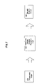
- FIG. 7 illustrates a high-level block diagram of one implementation of preservation logic 106 transmitting all or part of a content of memory device logic 104 to serial-use device content reception logic 700 .
- FIG. 8 illustrates a high-level logic flowchart of a process.
- Method step 800 shows the start of the process.
- FIG. 9 shows a high-level logic flowchart depicting alternate implementations of the high-level logic flowchart of FIG. 8 .
- FIG. 10 depicts a high-level logic flowchart illustrating alternate implementations of the high-level logic flowchart of FIG. 8 .
- FIG. 12 shows a high-level logic flowchart illustrating at least one alternate implementation of the high-level logic flowchart of FIG. 4 .
- serial-use device 100 contains memory device logic 104 , upcoming-purge detection logic 102 , and preservation logic 106 .
- upcoming-purge detection logic 102 , memory device logic 104 , and preservation logic 106 are at least partially formed from integrated circuits and are electrically interconnected (e.g., via conductors such as wires).
- conductors such as wires
- serial-use device can encompass both a multiple-use as well as a single use device, in that a series can consist of one and/or more than one element.
- the inventors point out that serial-use device 100 can entail a still image device (e.g., a digital still camera and/or playback device), a motion image device (e.g., a digital video camera and/or a playback device), a textual data device (e.g., a book recordation and/or playback device), and/or an audio recordation device.
- serial-use device 100 entails a computing device (e.g., a personal digital assistant (PDA), a blackberry, and/or or a cell phone).
- PDA personal digital assistant
- serial-use device 100 and upcoming-purge detection logic 102 , and preservation logic 106 are communicating via information exchanged across a distance.
- information can be exchanged wirelessly (e.g., via electromagnetic radiation in substantially any portion of the electromagnetic spectrum).
- such information can be exchanged optically (e.g., via electromagnetic radiation in the optical spectrum).
- Method step 400 shows the start of the process.
- Method step 402 shows detecting a likelihood that a purge of a memory of a serial-use device is forthcoming (e.g., via upcoming-purge detection logic 102 and/or its supporting components).
- Method step 404 depicts transmitting a content of the memory of the serial-use device in response to said detecting (e.g., via preservation logic 106 ).
- Method step 406 shows the end of the process.
- method step 402 includes method step 500 , and/or method step 502 , and/or method step 504 , and/or method step 506 .
- Method step 500 shows detecting a proximity to a return bin (e.g., via upcoming-purge detection logic 102 communicating with a beacon in the return bin, such as might be used at a rental concern).
- Method step 502 depicts detecting a proximity to a number of authorized uses (e.g., detecting that a number of authorized uses have been or are about to be performed via upcoming-purge detection logic 102 tracking a number of uses of serial-use device 100 and comparing such tracked number of uses against a known authorized number of uses).
- Method step 504 illustrates detecting a proximity to a duration of authorized use (e.g., detecting that a duration of authorized use has expired and/or will expire via upcoming-purge detection logic 102 tracking an elapsed time since serial-use device 100 left a rental facility and comparing such tracked elapsed time against a known authorized duration of time).
- Method step 506 illustrates detecting a proximity to an end of a rental parameter (e.g., detecting that one or more of any number of rental parameters are at or near their respective ends via upcoming-purge detection logic 102 tracking such one or more rental parameters in an appropriate fashion).
- method step 404 includes method step 600 , and/or method step 602 , and/or method step 604 , and/or method step 606 , and/or method steps 608 - 610 , and/or methods step 612 - 614 .
- Method step 600 depicts transmitting the content of the memory to a storage device (e.g., via preservation logic 106 transmitting all or part of the contents of memory device logic 104 to a storage device such as a EEPROM, a flash memory device, a rotating medium device (e.g., a magnetic disc drive and/or an optical disc drive), and/or a network storage device, etc.).
- Method step 602 illustrates transmitting the content of the memory onto a wireless link (e.g., via preservation logic 106 transmitting all or part of the contents of memory device logic 104 to a storage device through a wireless network such as an ad-hoc wireless network, and/or a cellular wireless network, and/or a point to point wireless link, etc.).
- Method step 604 illustrates transmitting the content of the memory onto an electrical link (e.g., via preservation logic 106 transmitting all or part of the contents of memory device logic 104 to a storage device through a serial and/or parallel electrical connection such as those used to interface with a flash external drive, a rotating media drive, a micro-disc drive, a random access memory, an EEPROM memory, etc).
- Method step 606 shows transmitting the content of the memory onto an optical link (e.g., via preservation logic 106 transmitting all or part of the contents of memory device logic 104 to a storage device through a serial and/or parallel optical connection such as those used by fiber-optic networks and or those used in point-to-point optical connections, etc).
- Method step 608 depicts obtaining an address from a device either proximate to and/or associated with a user (e.g., via preservation logic 106 communicating with a personal device associated with a human user, such as a Radio Frequency Identification (RFID) dog tag, a swinging Bluetooth medallion, a wristwatch, an input mechanism of serial use device 100 (e.g., button, keyboard input, voice input, etc.), etc. and obtaining an address such as a network, world wide web, and/or other appropriate type address, etc from the personal device).
- RFID Radio Frequency Identification
- Method step 610 illustrates transmitting the content of the memory using the address (e.g., via preservation logic 106 transmitting via ways described/illustrated elsewhere herein and/or over a personal area network (PAN) using some appropriate technology such as ultra wide band (UWB)).
- PAN personal area network
- UWB ultra wide band
- Method step 612 shows presenting at least one transmission option (e.g., via preservation logic 106 presenting to the user one or more transmission options (e.g., to transmit all or only a part of the content of the memory, such as, for example, only a select digital photograph, and/or digital video, and/or digital audio) through a device accessible by a human/robotic user, such as a Radio Frequency Identification (RFID) dog tag, a swinging Bluetooth medallion, a wristwatch, a presentation mechanism of serial use device 100 (e.g., liquid crystal display, text output, voice output, etc.), etc.).
- RFID Radio Frequency Identification
- Method step 614 depicts transmitting the content of the memory in response to the presented at least one transmit option (e.g., via preservation logic 106 transmitting the selected content via ways described/illustrated elsewhere herein and/or over a personal area network (PAN) using some appropriate technology such as ultra wide band (UWB)).
- PAN personal area network
- UWB ultra wide band
- preservation logic 106 transmitting all or part of a content of memory device logic 104 to serial-use device content reception logic 700 .
- the large arrow shown between preservation logic 106 and serial-use device content reception logic 700 will be recognized by those having skill in the art as indicative of appropriate communications coupling technologies.
- preservation logic 106 communicates over an electrical coupling such as those provided by a parallel and/or a serial port electrical connection.
- preservation logic 106 communicates over an optical coupling such as that provided by a fiber optic cable, a point to point optical channel, an optical network, etc.
- preservation logic 106 communicates over a wireless coupling such as that provided by a cellular communications network, a point to point wireless channel, etc.
- serial-use device content reception logic 700 transmits the received content to storage medium device 702 .
- the large arrow shown between serial-use device content reception logic 700 and storage medium device 702 will be recognized by those having skill in the art as indicative of appropriate communications coupling technologies.
- serial-use device content reception logic 700 communicates over an electrical coupling such as may be provided by a parallel and/or a serial port electrical connection.
- serial-use device content reception logic 700 communicates over an optical coupling such as may be provided by a fiber optic cable, a point to point optical channel, an optical network, etc.
- serial-use device content reception logic 700 communicates over a wireless coupling such as that provided by a cellular communications network, a point to point wireless channel, etc.
- preservation logic 106 and/or serial-use device content reception logic 700 are at least partially formed with integrated circuits.
- storage medium device 702 may include a moving medium, such as a micro-disc drive, a standard hard disk drive, an optical disk drive, etc.
- storage medium device 702 may include a non-moving medium, such as a flash external drive, various types of random access memory (e.g., standard RAM, SRAM, DRAM, etc.), read only memory (e.g., ROM, EPROM, EEPROM, programmable gate arrays, etc.)
- Method step 800 shows the start of the process.
- Method step 802 shows receiving a content of a memory of a serial-use device transmitted in response to a detection of a likelihood of a purge of the memory of the serial-use device (e.g., via upcoming-purge detection logic 102 and/or its supporting components).
- Method step 804 depicts storing the content of the memory of the serial-use device (e.g., via preservation logic 106 ).
- Method step 806 shows the end of the process.
- method step 802 includes method step 900 , and/or method step 902 , and/or method step 904 , and/or method step 906 .
- Method step 900 shows receiving the content of the memory in conjunction with an indicator of at least one of an identifier of the serial-use device or an identity associated with the content (e.g., via serial-use device content reception logic 700 receiving the content of preservation logic 106 in conjunction with an identifier of serial-use device 100 and/or the user of serial-use device 100 ).
- method step 804 includes method step 1000 .
- Method step 1000 depicts storing at least a part of the content of the memory to at least one of a substantially moving medium device or a substantially stationary medium device (e.g., via serial-use device content reception logic 700 transmitting all or part of the content and/or indicator to storage medium device 702 that may entail a substantially moving device such as an appropriate rotating medium drive and/or a substantially non moving—or substantially stationary—device such as an EEPROM, a flash memory device, RAM, ROM, programmable gate array, etc.)
- a substantially moving device such as an appropriate rotating medium drive and/or a substantially non moving—or substantially stationary—device such as an EEPROM, a flash memory device, RAM, ROM, programmable gate array, etc.
- preservation logic 106 retrieves all or part of a content of memory device logic 104 from storage medium device 702 through content recall and transmit logic 1100 .
- the large arrows shown between preservation logic 106 , content recall and transmit logic 1100 , and storage medium device 702 will be recognized by those having skill in the art as indicative of appropriate communications coupling technologies.
- preservation logic 106 communicates over an electrical coupling such as those provided by a parallel and/or a serial port electrical connection.
- preservation logic 106 communicates over an optical coupling such as that provided by a fiber optic cable, a point to point optical channel, an optical network, etc.
- preservation logic 106 communicates over a wireless coupling such as that provided by a cellular communications network, a point to point wireless channel, etc.
- content recall and transmit logic 1100 retrieves a previously received content from storage medium device 702 (e.g., as in helping perform an undo operation as described herein).
- the large arrow shown between content recall and transmit logic 1100 and storage medium device 702 will be recognized by those having skill in the art as indicative of appropriate communications coupling technologies.
- content recall and transmit logic 1100 communicates over an electrical coupling such as may be provided by a parallel and/or a serial port electrical connection.
- content recall and transmit logic 1100 communicates over an optical coupling such as may be provided by a fiber optic cable, a point to point optical channel, an optical network, etc.
- content recall and transmit logic 1100 communicates over a wireless coupling such as that provided by a cellular communications network, a point to point wireless channel, etc.
- preservation logic 106 and/or content recall and transmit logic 1100 are at least partially formed with integrated circuits.
- storage medium device 702 may include a moving medium, such as a micro-disc drive, a standard hard disk drive, an optical disk drive, etc.
- storage medium device 702 may include a non-moving medium, such as a flash external drive, various types of random access memory (e.g., standard RAM, SRAM, DRAM, etc.), read only memory (e.g., ROM, EPROM, EEPROM, programmable gate arrays, etc.)
- FIG. 12 shown is a high-level logic flowchart illustrating at least one alternate implementation of the high-level logic flowchart of FIG. 4 . Shown is that in at least one alternate implementation, the process of FIG. 4 includes method step 405 .
- Method step 405 depicts retrieving at least a part of the transmitted content using an address (e.g., via preservation logic 106 retrieving all or part of the contents of memory device logic 104 from a storage device such as a EEPROM, a flash memory device, a rotating medium device (e.g., a magnetic disc drive and/or an optical disc drive), and/or a network storage device, etc.)—the inventors point out that the retrieved content can entail retrieving a transformed version of the transmitted content, such as a token.
- the remaining method steps of FIG. 12 function analogously to similar steps shown/described elsewhere herein.
- method step 405 includes method steps 1300 - 1302 and/or method steps 1304 - 1306 .
- Method step 1300 illustrates accepting an undo input (e.g., via preservation logic 106 receiving such input through a personal device associated with a human user, such as a Radio Frequency Identification (RFID) dog tag, a swinging Bluetooth medallion, a wristwatch, an input mechanism of serial use device 100 (e.g., button, keyboard input, voice input, etc.).
- Method step 1302 shows retrieving at least a part of the transmitted content in response to the accepted undo input (e.g., preservation logic 106 retrieving at least a part of previously transmitted content from storage medium device 702 through content recall and transmit logic 1100 ).
- RFID Radio Frequency Identification
- method step 1304 illustrates accepting a re-rent input (e.g., via preservation logic 106 receiving such input through a personal device associated with a human user, such as a Radio Frequency Identification (RFID) dog tag, a swinging Bluetooth medallion, a wristwatch, an input mechanism of serial use device 100 (e.g., button, keyboard input, voice input, etc.).
- Method step 1306 shows retrieving at least a part of the transmitted content in response to the accepted re-rent input (e.g., preservation logic 106 retrieving at least a part of previously transmitted content from storage medium device 702 through content recall and transmit logic 1100 ).
- RFID Radio Frequency Identification
- an implementer may opt for a mainly hardware and/or firmware vehicle; alternatively, if flexibility is paramount, the implementer may opt for a mainly software implementation; or, yet again alternatively, the implementer may opt for some combination of hardware, software, and/or firmware.
- any vehicle to be utilized is a choice dependent upon the context in which the vehicle will be deployed and the specific concerns (e.g., speed, flexibility, or predictability) of the implementer, any of which may vary.
- Those skilled in the art will recognize that optical aspects of implementations will require optically-oriented hardware, software, and or firmware.
- a signal bearing media include, but are not limited to, the following: recordable type media such as floppy disks, hard disk drives, CD ROMs, digital tape, and computer memory; and transmission type media such as digital and analog communication links using TDM or IP based communication links (e.g., packet links).
- electrical circuitry includes, but is not limited to, electrical circuitry having at least one discrete electrical circuit, electrical circuitry having at least one integrated circuit, electrical circuitry having at least one application specific integrated circuit, electrical circuitry forming a general purpose computing device configured by a computer program (e.g., a general purpose computer configured by a computer program which at least partially carries out processes and/or devices described herein, or a microprocessor configured by a computer program which at least partially carries out processes and/or devices described herein), electrical circuitry forming a memory device (e.g., forms of random access memory), and/or electrical circuitry forming a communications device (e.g., a modem, communications switch, or optical-electrical equipment).
- a computer program e.g., a general purpose computer configured by a computer program which at least partially carries out processes and/or devices described herein, or a microprocessor configured by a computer program which at least partially carries out processes and/or devices described herein
- electrical circuitry forming a memory device
- any two components so associated can also be viewed as being “operably connected”, or “operably coupled”, to each other to achieve the desired functionality, and any two components capable of being so associated can also be viewed as being “operably couplable”, to each other to achieve the desired functionality.
- operably couplable include but are not limited to physically mateable and/or physically interacting components and/or wirelessly interactable and/or wirelessly interacting components.
Abstract
Description
Claims (31)
Priority Applications (4)
| Application Number | Priority Date | Filing Date | Title |
|---|---|---|---|
| US10/973,930 US7441089B2 (en) | 2004-10-25 | 2004-10-25 | Preserving content of serial use devices in view of purge |
| EP05824201A EP1834240A4 (en) | 2004-10-25 | 2005-10-25 | Preserving content of serial use devices in view of purge |
| CN2005800442044A CN101297273B (en) | 2004-10-25 | 2005-10-25 | Preserving content of serial use devices in view of purge |
| PCT/US2005/038496 WO2006047567A2 (en) | 2004-10-25 | 2005-10-25 | Preserving content of serial use devices in view of purge |
Applications Claiming Priority (1)
| Application Number | Priority Date | Filing Date | Title |
|---|---|---|---|
| US10/973,930 US7441089B2 (en) | 2004-10-25 | 2004-10-25 | Preserving content of serial use devices in view of purge |
Publications (2)
| Publication Number | Publication Date |
|---|---|
| US20060090037A1 US20060090037A1 (en) | 2006-04-27 |
| US7441089B2 true US7441089B2 (en) | 2008-10-21 |
Family
ID=36207339
Family Applications (1)
| Application Number | Title | Priority Date | Filing Date |
|---|---|---|---|
| US10/973,930 Expired - Fee Related US7441089B2 (en) | 2004-10-25 | 2004-10-25 | Preserving content of serial use devices in view of purge |
Country Status (4)
| Country | Link |
|---|---|
| US (1) | US7441089B2 (en) |
| EP (1) | EP1834240A4 (en) |
| CN (1) | CN101297273B (en) |
| WO (1) | WO2006047567A2 (en) |
Citations (18)
| Publication number | Priority date | Publication date | Assignee | Title |
|---|---|---|---|---|
| US5423086A (en) | 1992-10-19 | 1995-06-06 | Motorola, Inc. | Dual port memory communication for a radio frequency device and a personal computer |
| US5537558A (en) | 1994-10-05 | 1996-07-16 | Halliburton Company | Apparatus and method for communicating multiple devices through one PCMCIA interface |
| US5812641A (en) * | 1994-10-28 | 1998-09-22 | Nippon T.M.I. Co., Ltd. | Method of renting portable-type communicating devices |
| US5878282A (en) | 1995-08-09 | 1999-03-02 | Microsoft Corporation | Portable information device and system and method for downloading executable instruction from a computer to the portable information device |
| US5889816A (en) | 1996-02-02 | 1999-03-30 | Lucent Technologies, Inc. | Wireless adapter architecture for mobile computing |
| US5978591A (en) | 1998-02-24 | 1999-11-02 | Franklin Electronics Publishers, Inc. | Personal information device and method for downloading reprogramming data from a computer to the personal information device via the PCMCIA port or through a docking station with baud rate conversion means |
| US6189056B1 (en) | 1997-05-20 | 2001-02-13 | International Business Machines Corporation | Information processing terminal |
| US6202209B1 (en) | 1998-02-24 | 2001-03-13 | Xircom, Inc. | Personal information device and method for downloading reprogramming data from a computer to the personal information device via the PCMCIA port or through a docking station with baud rate conversion means |
| US20010012060A1 (en) * | 1996-06-20 | 2001-08-09 | Asahi Kogaku Kogyo Kabushiki Kaisha | Still video camera, remote controller and camera system |
| US6310634B1 (en) | 1997-08-04 | 2001-10-30 | Starfish Software, Inc. | User interface methodology supporting light data entry for microprocessor device having limited user input |
| US6356583B1 (en) | 1997-07-16 | 2002-03-12 | Samsung Electronics Co., Ltd. | Device and method for controlling the baud rate between a portable telephone and an external device |
| US20030048358A1 (en) * | 2001-09-12 | 2003-03-13 | Hideyuki Shirai | Digital camera recycle system |
| US20040006517A1 (en) | 2000-02-23 | 2004-01-08 | Sunao Takatori | Rental machine and storage medium |
| US6687743B1 (en) * | 2000-02-24 | 2004-02-03 | International Business Machines Corporation | Client server communications for a mobile computing device |
| US6754765B1 (en) | 2001-05-14 | 2004-06-22 | Integrated Memory Logic, Inc. | Flash memory controller with updateable microcode |
| US20050124332A1 (en) * | 2003-12-08 | 2005-06-09 | Clark David R. | Mobile device programming system and method |
| US20060072755A1 (en) * | 2000-10-13 | 2006-04-06 | Koskimies Oskari | Wireless lock system |
| US7170259B2 (en) * | 2003-06-11 | 2007-01-30 | Research In Motion Limited | Universal serial bus charger for a mobile device |
Family Cites Families (3)
| Publication number | Priority date | Publication date | Assignee | Title |
|---|---|---|---|---|
| JP3962824B2 (en) * | 2000-05-12 | 2007-08-22 | カシオ計算機株式会社 | Multi-rental bending machine system |
| US6914695B2 (en) * | 2001-08-08 | 2005-07-05 | International Business Machines Corporation | Process of operations with an interchangeable transmission device and apparatus for use therein for a common interface for use with digital cameras |
| CN1259639C (en) * | 2002-12-20 | 2006-06-14 | 财团法人资讯工业策进会 | Intellgent image data storage managing method and device |
-
2004
- 2004-10-25 US US10/973,930 patent/US7441089B2/en not_active Expired - Fee Related
-
2005
- 2005-10-25 CN CN2005800442044A patent/CN101297273B/en not_active Expired - Fee Related
- 2005-10-25 EP EP05824201A patent/EP1834240A4/en not_active Withdrawn
- 2005-10-25 WO PCT/US2005/038496 patent/WO2006047567A2/en active Application Filing
Patent Citations (18)
| Publication number | Priority date | Publication date | Assignee | Title |
|---|---|---|---|---|
| US5423086A (en) | 1992-10-19 | 1995-06-06 | Motorola, Inc. | Dual port memory communication for a radio frequency device and a personal computer |
| US5537558A (en) | 1994-10-05 | 1996-07-16 | Halliburton Company | Apparatus and method for communicating multiple devices through one PCMCIA interface |
| US5812641A (en) * | 1994-10-28 | 1998-09-22 | Nippon T.M.I. Co., Ltd. | Method of renting portable-type communicating devices |
| US5878282A (en) | 1995-08-09 | 1999-03-02 | Microsoft Corporation | Portable information device and system and method for downloading executable instruction from a computer to the portable information device |
| US5889816A (en) | 1996-02-02 | 1999-03-30 | Lucent Technologies, Inc. | Wireless adapter architecture for mobile computing |
| US20010012060A1 (en) * | 1996-06-20 | 2001-08-09 | Asahi Kogaku Kogyo Kabushiki Kaisha | Still video camera, remote controller and camera system |
| US6189056B1 (en) | 1997-05-20 | 2001-02-13 | International Business Machines Corporation | Information processing terminal |
| US6356583B1 (en) | 1997-07-16 | 2002-03-12 | Samsung Electronics Co., Ltd. | Device and method for controlling the baud rate between a portable telephone and an external device |
| US6310634B1 (en) | 1997-08-04 | 2001-10-30 | Starfish Software, Inc. | User interface methodology supporting light data entry for microprocessor device having limited user input |
| US6202209B1 (en) | 1998-02-24 | 2001-03-13 | Xircom, Inc. | Personal information device and method for downloading reprogramming data from a computer to the personal information device via the PCMCIA port or through a docking station with baud rate conversion means |
| US5978591A (en) | 1998-02-24 | 1999-11-02 | Franklin Electronics Publishers, Inc. | Personal information device and method for downloading reprogramming data from a computer to the personal information device via the PCMCIA port or through a docking station with baud rate conversion means |
| US20040006517A1 (en) | 2000-02-23 | 2004-01-08 | Sunao Takatori | Rental machine and storage medium |
| US6687743B1 (en) * | 2000-02-24 | 2004-02-03 | International Business Machines Corporation | Client server communications for a mobile computing device |
| US20060072755A1 (en) * | 2000-10-13 | 2006-04-06 | Koskimies Oskari | Wireless lock system |
| US6754765B1 (en) | 2001-05-14 | 2004-06-22 | Integrated Memory Logic, Inc. | Flash memory controller with updateable microcode |
| US20030048358A1 (en) * | 2001-09-12 | 2003-03-13 | Hideyuki Shirai | Digital camera recycle system |
| US7170259B2 (en) * | 2003-06-11 | 2007-01-30 | Research In Motion Limited | Universal serial bus charger for a mobile device |
| US20050124332A1 (en) * | 2003-12-08 | 2005-06-09 | Clark David R. | Mobile device programming system and method |
Non-Patent Citations (3)
| Title |
|---|
| "Optical Fiber", Microsoft Computer Dictionary, Fifth edition; Microsoft Press; Redmond, Washington; p. 379 (total of 3 pages-including cover and publication pages) bearing a date of 2002. |
| PCT International Search Report; International App. No. PCT/US05/38838; Jan. 31, 2007. |
| PCT International Search Report; International App. No.: PCT/US05/38496; pp. 1-3; Jun. 25, 2008. |
Also Published As
| Publication number | Publication date |
|---|---|
| WO2006047567A2 (en) | 2006-05-04 |
| EP1834240A4 (en) | 2009-12-02 |
| EP1834240A2 (en) | 2007-09-19 |
| US20060090037A1 (en) | 2006-04-27 |
| CN101297273B (en) | 2012-05-16 |
| CN101297273A (en) | 2008-10-29 |
| WO2006047567A3 (en) | 2009-04-09 |
Similar Documents
| Publication | Publication Date | Title |
|---|---|---|
| CN1756100B (en) | Radio communication system, radio communication device, and radio communication method | |
| EP1855389A1 (en) | Method of routing input and output data in an NFC chipset | |
| EP0614303A1 (en) | Method for delivering a telephone number associated with a telephone subscription, telephones and mobile telephone using the method | |
| CN107852587A (en) | The combination of bluetooth low energy is monitored and scanning window | |
| CN106990912A (en) | The method of control SIM card and SD card and realize the electronic equipment of the card | |
| CN106464345B (en) | Interference management techniques for Full-duplex wireless communications | |
| WO2011039123A1 (en) | Matching method, system and device for data exchange between a communication object and a processing unit | |
| ES2268564T3 (en) | SYSTEM AND METHOD OF RECOVERY OF TELEPHONE NUMBERS. | |
| EP1695576B1 (en) | Method and device for pre-saving personal data for a subscriber to a telecommunications network | |
| CN105843361A (en) | Method for reducing power consumption while photographing, and mobile terminal | |
| US7441089B2 (en) | Preserving content of serial use devices in view of purge | |
| EP2027700A1 (en) | Transmission of data between a server and a communicating object | |
| EP1304007A1 (en) | Method for interactive exchange between a subscriber identification module co-operating with a terminal in a radiotelephone, and a local device | |
| FR2983027A1 (en) | METHOD FOR SELECTING AN APPLICATION IN A TERMINAL, AND TERMINAL USING THE SAME | |
| KR101661232B1 (en) | Method for providing contents to external apparatus | |
| US20060171363A1 (en) | Wireless Transfer of Digital Video Data | |
| US20060090038A1 (en) | Auto purge of serial use devices | |
| EP1041834A1 (en) | Telecommunications terminal with operator managed short message storage and corresponding method | |
| CN110162238A (en) | It is a kind of fast to call associated application method and device, mobile terminal and storage medium | |
| EP4285491A1 (en) | Method and device for adapting a near-field communication | |
| EP3085162B1 (en) | Radio-communication system including means for associating a radio-communication terminal with a radio-communication station, radio-communication station, radio-communication terminal and association method | |
| CN106412065A (en) | Device control methods and apparatuses | |
| EP3038396B1 (en) | Beacon with multiple communication interfaces with secure deactivation/reactivation | |
| WO2006122871A1 (en) | Method for automatically replacing a user identifying module in a terminal | |
| WO2005013580A1 (en) | Method, mobile terminal, and computer cards and programs enabling an on-board application on a terminal to communicate with a resident application in a sim card |
Legal Events
| Date | Code | Title | Description |
|---|---|---|---|
| AS | Assignment |
Owner name: SEARETE LLC, WASHINGTON Free format text: ASSIGNMENT OF ASSIGNORS INTEREST;ASSIGNORS:JUNG, EDWARD K.Y.;LEVIEN, ROYCE A.;MALAMUD, MARK A.;AND OTHERS;REEL/FRAME:016138/0046;SIGNING DATES FROM 20041123 TO 20041221 |
|
| STCF | Information on status: patent grant |
Free format text: PATENTED CASE |
|
| FEPP | Fee payment procedure |
Free format text: PAYOR NUMBER ASSIGNED (ORIGINAL EVENT CODE: ASPN); ENTITY STATUS OF PATENT OWNER: LARGE ENTITY |
|
| AS | Assignment |
Owner name: INVENTION SCIENCE FUND I, WASHINGTON Free format text: ASSIGNMENT OF ASSIGNORS INTEREST;ASSIGNOR:SEARETE LLC;REEL/FRAME:023484/0742 Effective date: 20091106 |
|
| FPAY | Fee payment |
Year of fee payment: 4 |
|
| CC | Certificate of correction | ||
| REMI | Maintenance fee reminder mailed | ||
| FPAY | Fee payment |
Year of fee payment: 8 |
|
| SULP | Surcharge for late payment |
Year of fee payment: 7 |
|
| FEPP | Fee payment procedure |
Free format text: MAINTENANCE FEE REMINDER MAILED (ORIGINAL EVENT CODE: REM.); ENTITY STATUS OF PATENT OWNER: LARGE ENTITY |
|
| LAPS | Lapse for failure to pay maintenance fees |
Free format text: PATENT EXPIRED FOR FAILURE TO PAY MAINTENANCE FEES (ORIGINAL EVENT CODE: EXP.); ENTITY STATUS OF PATENT OWNER: LARGE ENTITY |
|
| STCH | Information on status: patent discontinuation |
Free format text: PATENT EXPIRED DUE TO NONPAYMENT OF MAINTENANCE FEES UNDER 37 CFR 1.362 |
|
| FP | Lapsed due to failure to pay maintenance fee |
Effective date: 20201021 |