US7460951B2 - System and method of target tracking using sensor fusion - Google Patents
System and method of target tracking using sensor fusion Download PDFInfo
- Publication number
- US7460951B2 US7460951B2 US11/235,679 US23567905A US7460951B2 US 7460951 B2 US7460951 B2 US 7460951B2 US 23567905 A US23567905 A US 23567905A US 7460951 B2 US7460951 B2 US 7460951B2
- Authority
- US
- United States
- Prior art keywords
- program
- track
- sensors
- function
- determined
- Prior art date
- Legal status (The legal status is an assumption and is not a legal conclusion. Google has not performed a legal analysis and makes no representation as to the accuracy of the status listed.)
- Active, expires
Links
Images


Classifications
-
- G—PHYSICS
- G01—MEASURING; TESTING
- G01S—RADIO DIRECTION-FINDING; RADIO NAVIGATION; DETERMINING DISTANCE OR VELOCITY BY USE OF RADIO WAVES; LOCATING OR PRESENCE-DETECTING BY USE OF THE REFLECTION OR RERADIATION OF RADIO WAVES; ANALOGOUS ARRANGEMENTS USING OTHER WAVES
- G01S13/00—Systems using the reflection or reradiation of radio waves, e.g. radar systems; Analogous systems using reflection or reradiation of waves whose nature or wavelength is irrelevant or unspecified
- G01S13/88—Radar or analogous systems specially adapted for specific applications
- G01S13/93—Radar or analogous systems specially adapted for specific applications for anti-collision purposes
- G01S13/931—Radar or analogous systems specially adapted for specific applications for anti-collision purposes of land vehicles
-
- G—PHYSICS
- G01—MEASURING; TESTING
- G01S—RADIO DIRECTION-FINDING; RADIO NAVIGATION; DETERMINING DISTANCE OR VELOCITY BY USE OF RADIO WAVES; LOCATING OR PRESENCE-DETECTING BY USE OF THE REFLECTION OR RERADIATION OF RADIO WAVES; ANALOGOUS ARRANGEMENTS USING OTHER WAVES
- G01S13/00—Systems using the reflection or reradiation of radio waves, e.g. radar systems; Analogous systems using reflection or reradiation of waves whose nature or wavelength is irrelevant or unspecified
- G01S13/66—Radar-tracking systems; Analogous systems
- G01S13/72—Radar-tracking systems; Analogous systems for two-dimensional tracking, e.g. combination of angle and range tracking, track-while-scan radar
- G01S13/723—Radar-tracking systems; Analogous systems for two-dimensional tracking, e.g. combination of angle and range tracking, track-while-scan radar by using numerical data
- G01S13/726—Multiple target tracking
-
- G—PHYSICS
- G01—MEASURING; TESTING
- G01S—RADIO DIRECTION-FINDING; RADIO NAVIGATION; DETERMINING DISTANCE OR VELOCITY BY USE OF RADIO WAVES; LOCATING OR PRESENCE-DETECTING BY USE OF THE REFLECTION OR RERADIATION OF RADIO WAVES; ANALOGOUS ARRANGEMENTS USING OTHER WAVES
- G01S13/00—Systems using the reflection or reradiation of radio waves, e.g. radar systems; Analogous systems using reflection or reradiation of waves whose nature or wavelength is irrelevant or unspecified
- G01S13/86—Combinations of radar systems with non-radar systems, e.g. sonar, direction finder
- G01S13/862—Combination of radar systems with sonar systems
-
- G—PHYSICS
- G01—MEASURING; TESTING
- G01S—RADIO DIRECTION-FINDING; RADIO NAVIGATION; DETERMINING DISTANCE OR VELOCITY BY USE OF RADIO WAVES; LOCATING OR PRESENCE-DETECTING BY USE OF THE REFLECTION OR RERADIATION OF RADIO WAVES; ANALOGOUS ARRANGEMENTS USING OTHER WAVES
- G01S13/00—Systems using the reflection or reradiation of radio waves, e.g. radar systems; Analogous systems using reflection or reradiation of waves whose nature or wavelength is irrelevant or unspecified
- G01S13/86—Combinations of radar systems with non-radar systems, e.g. sonar, direction finder
- G01S13/865—Combination of radar systems with lidar systems
-
- G—PHYSICS
- G01—MEASURING; TESTING
- G01S—RADIO DIRECTION-FINDING; RADIO NAVIGATION; DETERMINING DISTANCE OR VELOCITY BY USE OF RADIO WAVES; LOCATING OR PRESENCE-DETECTING BY USE OF THE REFLECTION OR RERADIATION OF RADIO WAVES; ANALOGOUS ARRANGEMENTS USING OTHER WAVES
- G01S13/00—Systems using the reflection or reradiation of radio waves, e.g. radar systems; Analogous systems using reflection or reradiation of waves whose nature or wavelength is irrelevant or unspecified
- G01S13/86—Combinations of radar systems with non-radar systems, e.g. sonar, direction finder
- G01S13/867—Combination of radar systems with cameras
-
- G—PHYSICS
- G06—COMPUTING; CALCULATING OR COUNTING
- G06F—ELECTRIC DIGITAL DATA PROCESSING
- G06F18/00—Pattern recognition
- G06F18/20—Analysing
- G06F18/25—Fusion techniques
- G06F18/253—Fusion techniques of extracted features
-
- G—PHYSICS
- G06—COMPUTING; CALCULATING OR COUNTING
- G06V—IMAGE OR VIDEO RECOGNITION OR UNDERSTANDING
- G06V10/00—Arrangements for image or video recognition or understanding
- G06V10/70—Arrangements for image or video recognition or understanding using pattern recognition or machine learning
- G06V10/77—Processing image or video features in feature spaces; using data integration or data reduction, e.g. principal component analysis [PCA] or independent component analysis [ICA] or self-organising maps [SOM]; Blind source separation
- G06V10/80—Fusion, i.e. combining data from various sources at the sensor level, preprocessing level, feature extraction level or classification level
- G06V10/806—Fusion, i.e. combining data from various sources at the sensor level, preprocessing level, feature extraction level or classification level of extracted features
-
- G—PHYSICS
- G06—COMPUTING; CALCULATING OR COUNTING
- G06V—IMAGE OR VIDEO RECOGNITION OR UNDERSTANDING
- G06V20/00—Scenes; Scene-specific elements
- G06V20/50—Context or environment of the image
- G06V20/56—Context or environment of the image exterior to a vehicle by using sensors mounted on the vehicle
-
- G—PHYSICS
- G01—MEASURING; TESTING
- G01S—RADIO DIRECTION-FINDING; RADIO NAVIGATION; DETERMINING DISTANCE OR VELOCITY BY USE OF RADIO WAVES; LOCATING OR PRESENCE-DETECTING BY USE OF THE REFLECTION OR RERADIATION OF RADIO WAVES; ANALOGOUS ARRANGEMENTS USING OTHER WAVES
- G01S13/00—Systems using the reflection or reradiation of radio waves, e.g. radar systems; Analogous systems using reflection or reradiation of waves whose nature or wavelength is irrelevant or unspecified
- G01S13/88—Radar or analogous systems specially adapted for specific applications
- G01S13/93—Radar or analogous systems specially adapted for specific applications for anti-collision purposes
- G01S13/931—Radar or analogous systems specially adapted for specific applications for anti-collision purposes of land vehicles
- G01S2013/93185—Controlling the brakes
-
- G—PHYSICS
- G01—MEASURING; TESTING
- G01S—RADIO DIRECTION-FINDING; RADIO NAVIGATION; DETERMINING DISTANCE OR VELOCITY BY USE OF RADIO WAVES; LOCATING OR PRESENCE-DETECTING BY USE OF THE REFLECTION OR RERADIATION OF RADIO WAVES; ANALOGOUS ARRANGEMENTS USING OTHER WAVES
- G01S13/00—Systems using the reflection or reradiation of radio waves, e.g. radar systems; Analogous systems using reflection or reradiation of waves whose nature or wavelength is irrelevant or unspecified
- G01S13/88—Radar or analogous systems specially adapted for specific applications
- G01S13/93—Radar or analogous systems specially adapted for specific applications for anti-collision purposes
- G01S13/931—Radar or analogous systems specially adapted for specific applications for anti-collision purposes of land vehicles
- G01S2013/9321—Velocity regulation, e.g. cruise control
-
- G—PHYSICS
- G01—MEASURING; TESTING
- G01S—RADIO DIRECTION-FINDING; RADIO NAVIGATION; DETERMINING DISTANCE OR VELOCITY BY USE OF RADIO WAVES; LOCATING OR PRESENCE-DETECTING BY USE OF THE REFLECTION OR RERADIATION OF RADIO WAVES; ANALOGOUS ARRANGEMENTS USING OTHER WAVES
- G01S13/00—Systems using the reflection or reradiation of radio waves, e.g. radar systems; Analogous systems using reflection or reradiation of waves whose nature or wavelength is irrelevant or unspecified
- G01S13/88—Radar or analogous systems specially adapted for specific applications
- G01S13/93—Radar or analogous systems specially adapted for specific applications for anti-collision purposes
- G01S13/931—Radar or analogous systems specially adapted for specific applications for anti-collision purposes of land vehicles
- G01S2013/9322—Radar or analogous systems specially adapted for specific applications for anti-collision purposes of land vehicles using additional data, e.g. driver condition, road state or weather data
-
- G—PHYSICS
- G01—MEASURING; TESTING
- G01S—RADIO DIRECTION-FINDING; RADIO NAVIGATION; DETERMINING DISTANCE OR VELOCITY BY USE OF RADIO WAVES; LOCATING OR PRESENCE-DETECTING BY USE OF THE REFLECTION OR RERADIATION OF RADIO WAVES; ANALOGOUS ARRANGEMENTS USING OTHER WAVES
- G01S13/00—Systems using the reflection or reradiation of radio waves, e.g. radar systems; Analogous systems using reflection or reradiation of waves whose nature or wavelength is irrelevant or unspecified
- G01S13/88—Radar or analogous systems specially adapted for specific applications
- G01S13/93—Radar or analogous systems specially adapted for specific applications for anti-collision purposes
- G01S13/931—Radar or analogous systems specially adapted for specific applications for anti-collision purposes of land vehicles
- G01S2013/9327—Sensor installation details
- G01S2013/93271—Sensor installation details in the front of the vehicles
Definitions
- the present invention relates to object tracking systems, and more particularly, to a multi-sensor system and method of fusing data from a plurality of sensors, for more accurately estimating the location of a given object.
- Object tracking and target profiling systems have been developed as part of safety applications in various industries, including the aviation and automotive industries. These systems utilize periodic or continuous detection of objects and control algorithms to estimate various planar parameters of an object, such as the relative object range, range rate (i.e., closing or opening velocity), and azimuth position (i.e., bearing), as well as three-dimensional parameters where applicable, such as altitude or elevation, so as to avoid, follow, or otherwise survey the object. It is apparent that the ability of these systems to provide accurate estimations is crucial to achieving the desired benefits of their applications.
- a plurality of sensors is often utilized within a system.
- these sensors may include GPS, FM-CW radars, pulse and FSK radars, and CCD's, CMOS, or other camera/video image processors.
- these multiple-observer configurations generally operate to detect the same object, so as to provide back-up or redundant means of detection, and therefore, do not typically improve the overall accuracy of the system above that of the most accurate sensor.
- Multi-observer systems that have been developed to increase accuracy, such as phased-array-multi-beam-radar systems, typically require complex construction and expensive equipment to operate.
- an improved target tracking system and method utilizing a plurality of sensors and data fusion is presented for increasing the precision and certainty of system measurements above that of any single system sensor.
- the present invention is useful for expanding coverage by merging field-of-view, reducing the capture/recapture time of objects, decreasing the likelihood of producing false positives and false negatives, and increasing the range of feasible applications for which conventional sensors can be utilized.
- a first aspect of the present invention concerns a target tracking and sensor fusion system for estimating a condition of at least one object.
- the system includes a first sensor configured to determine a first estimate of a condition of the object, and a second sensor configured to determine a second estimate of the condition.
- the system further includes a controller communicatively coupled to the sensors, and configured to determine a third estimate of the condition.
- the third estimate is based in part on the first and second estimates, and each of the first and second estimates includes a measured value and a standard of deviation.
- the third estimate presents a calculated value and a standard of deviation less than each of the first and second standards of deviation.
- a second aspect of the present invention concerns a computer program for execution by at least one electronic device associated with a plurality of sensors, wherein each of the sensors are configured to estimate at least one condition of at least one object.
- the program is configured to receive initial estimate data of said at least one condition from the sensors, and apply a sensory fusion algorithm to the initial estimate data, so as to determine a state estimate for said at least one condition.
- the state estimate presents a higher probability and smaller standard of deviation than the initial estimate data.
- the sensor fusion algorithm is applied to a land vehicle having a plurality of like or dissimilar sensors to increase the robustness of object detection.
- applications such as full speed automatic cruise control (ACC), auto braking, and precrash systems, can be enhanced.
- FIG. 1 is a plan view of a vehicle in accordance with a preferred embodiment of the present invention, particularly illustrating components of a preferred target tracking and sensory fusion system;
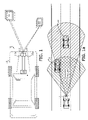
- FIG. 1 a is a plan view of a vehicle in accordance with a preferred embodiment of the present invention, wherein the vehicle travels upon a thoroughfare and uses multiple sensors to track two traveling remote vehicles;
- FIG. 2 is a block diagram of a preferred embodiment of the system, particularly illustrating the interrelation between the observation, data association and clustering, and track life management modules;
- FIG. 3 is a block diagram of a preferred embodiment of the sensory fusion process, including radar and vision sensors;
- FIG. 4 is a flow chart of a preferred embodiment of the control algorithm with respect to track life management.
- the present invention concerns an improved target tracking and sensory fusion system 10 .
- the system 10 is adapted for use with a vehicle 12 having a plurality of sensors configured to detect the location of and track at least one object.
- the system 10 utilizes an algorithm to receive condition data from the sensors and determine a more precise and accurate estimation of the condition.
- the system 10 is shown in FIGS. 1 and 1 a having a plurality of two sensors 14 , 16 , and tracking two objects (i.e. targets) 18 , 20 .
- the present invention may be utilized in air traffic control, nautical navigation, and weapons guidance systems.
- the algorithm utilizes a fusion method based on Kalman filtering (KF). It is appreciated by those ordinarily skilled in the art that a KF application is used to explore correlative characteristics of each target 18 , 20 along a temporal axis. In other words, it is assumed that the tracked target moves smoothly over a period of time.
- the system 10 is further configured to capture the spatial correlation (i.e., the relative position of each object as observed by multiple sensors).
- a preferred embodiment of the system 10 generally includes an observation module 22 , a data association and clustering (DAC) module 24 that further includes a Kalman filter 24 a , and a track life management (TLM) module 26 that keeps track of a track list 26 a comprising of a plurality of object tracks.
- the observation module consists of sensors, their respective sensor processors, and the interconnection between the sensors, sensor processors, and the DAC module.
- these sensors may include GPS systems, charged-coupled device (CCD) or complementary metal oxide semi-conductor (CMOS) video image sensors, long and medium range radar and lidar sensors, and ultrasonic sensors. These sensors are preferably positioned within the vehicle in relatively unobstructed positions.
- radar sensors can usually estimate range, range rate and azimuth location of an object, but is not normally robust in estimating the extent of a detected object.
- a camera with vision processor is more robust in estimating the shape and azimuth position of the object, but is less efficient at estimating the range and range rate of the object.
- Scanning type Lidars perform efficiently and accurately with respect to estimating range, and azimuth position, but cannot estimate range rate, and is therefore not accurate with respect to new object acquisition/recognition.
- Ultrasonic sensors are capable of estimating range but are generally incapable of estimating or computing range rate and azimuth position. Further, it is appreciated that the performance of each sensor technology is impacted by differing environmental conditions. Thus, conventional sensors present parametric variances, but more importantly, the operative overlap of these sensors (see, FIG. 1 a ) creates opportunities for sensory fusion.
- the illustrated observation module 22 includes a radar sensor 14 , a radar processor 14 a , a camera 16 , and a vision processor 16 a .
- the radar processor 14 a converts signals received from the radar 14 to determine range (R R ), range rate ( ⁇ dot over (R) ⁇ R ), and azimuth angle (1 R ) estimates for each of the objects 18 , 20 .
- the vision processor 16 a converts signals received from the camera 16 to also determine a second set of range (R V ), range rate ( ⁇ dot over (R) ⁇ V ), and azimuth angle (1 V ) estimates for the objects 18 , 20 .
- the preferred DAC module 24 includes a controller 28 , wherein a computer program (not shown) is stored and configured to receive the estimate data from each of the plurality of sensors, to cluster the data into like observation tracks (i.e. observations of the same object by multiple sensors), and to fuse the clustered observations to determine a true track status.
- a computer program (not shown) is stored and configured to receive the estimate data from each of the plurality of sensors, to cluster the data into like observation tracks (i.e. observations of the same object by multiple sensors), and to fuse the clustered observations to determine a true track status.
- fusing data of sensors from different technologies yield more robust results. Again, it is appreciated that any number of sensors can be used in this technique, and that the more sensors fused the more robust the results. However, it is also appreciated that an increased number of sensors results in increased algorithm complexity, and the requirement of more computing power to produce results within the same time frame.
- the preferred controller 28 is housed within the host vehicle 12 , but may also be located at a remote location. In this
- the preferred TLM module 26 is configured to then receive the fused data of liked observations, and store the fused observations in a list of tracks 26 a .
- the TLM module 26 is further configured to distinguish tracks according to their immanence. More preferably, the TLM module is configured to assign to each track a strength value, and to add to or subtract from the initial strength a predetermined value or at a predetermined rate each cycle depending upon whether a like observation was made during the cycle.
- FIG. 3 a block diagram of an exemplary system is shown in FIG. 3 , where two sensory systems, (i) radar with radar processor, and (ii) camera with vision processor, capture and transmit to the sensor fusion controller 28 observation estimates.
- the preferred controller 28 is configured to apply a sensor fusion algorithm to the observation estimates, and uses these inputs to generate a more accurate fused track, wherein the term “more accurate” is defined by a more probable estimated location and a reduced standard of deviation (i.e. a taller and narrower statistical bell-curve).
- the preferred controller 28 is further configured to store data over a period and utilize multiple data entries of a first condition to determine a second condition estimate.
- the fusion algorithm may be implemented in a real-time system having suitable hardware and interface configuration.
- v k is a 4-by-1 white Guassian noise vector with v k ⁇ N(0,Q) and Q is the covariance matrix.
- the preferred controller 28 is further configured to compare a subsequent observation with each track, so as to determine a track match.
- each observation is assigned to a track based on a metrics.
- j 1, . . . ,q ⁇ respectively.
- Each of the difference parameters is passed through a function empirically derived from the characteristics of the radar and vision sensing systems, and designated as ⁇ R ( ⁇ R), ⁇ ⁇ dot over (R) ⁇ ( ⁇ dot over (R) ⁇ ), and f ⁇ ( ⁇ ), respectively.
- L k,i k R ⁇ R ( ⁇ R k,i )+ k ⁇ dot over (R) ⁇ ⁇ ⁇ dot over (R) ⁇ ( ⁇ ⁇ dot over (R) ⁇ k,i )+ k ⁇ ⁇ ⁇ ( ⁇ k,i ) (4).
- the quantity L k,i indicates the merit that O i matches the k-th track.
- the three functions ⁇ R ( ⁇ R), f ⁇ dot over (R) ⁇ ( ⁇ dot over (R) ⁇ ), and ⁇ ⁇ ( ⁇ ) define windows that depend on the accuracy of the radar and vision sensors 14 , 16 in estimating the corresponding parameters.
- the constants k R , k ⁇ dot over (R) ⁇ , and k ⁇ define the weights of parameters used in decision making and are based on the robustness of individual sensor parameters.
- a merit function value (L i ) of an observation O i equal to
- the functions ⁇ R ( ⁇ R), ⁇ ⁇ dot over (R) ⁇ ( ⁇ dot over (R) ⁇ ) and ⁇ ⁇ ( ⁇ ) may be designed using various techniques, including a likelihood function (e.g. fuzzy logic) methodology. However, a symmetric kernel function (K(•)) is preferred in the illustrated embodiment. For example, the following formula may be utilized:
- f R ⁇ ( ⁇ ⁇ ⁇ R ) K ⁇ ( ⁇ ⁇ ⁇ R h R ) , ( 5 )
- h R denotes a scaling factor reflective of sensor characteristics. More particularly, two typical kernel functions may be used:
- K ⁇ ( u ) ⁇ ( 1 - d 2 ) if ⁇ ⁇ ⁇ d ⁇ ⁇ 1 , 0 otherwise .
- G [ 1 1 1 0 ]
- w i is a 3-by-1 white Guassian observer noise vector with w i ⁇ N(0,R i ) and the covariance matrix (R i ) is derived from the accuracy specification of the observing sensor.
- the P(t+1) matrix is the first-order covariance matrix of y(t+1), and represents the confidence level (i.e. the level of variance from the mean) of the estimate y(t+1). It is appreciated that P(t) is recursively calculated based on formulas (8) and (9).
- the initial values of y(0) and P(0) are determined using sensory input at a time frame 0. That is to say, whenever a new track is introduced, the unmatched sensor observation is used for y(0) and a heuristically defined constant is used for P(0).
- the preferred system 10 is further configured to monitor the life of each track. That is to say, the system 10 is configured to initiate a new track upon an observation that has not been associated to any of the existing tracks, and is able to determine whether an existing track should be withdrawn from the list 26 a .
- the TLM module 26 facilitates the retention of an accurate state vector Y(t).
- a quantity q k (t) is attributed to each track y k to denote its strength.
- a preferred method of track life management begins at a step 100 , where the value q k (t) decays at a rate ( ⁇ ), and more preferably, at an exponential rate.
- the values q k (t) and ⁇ may be constant with respect to each track or may vary depending upon track characteristics. For example, tracks comprising of relatively peripheral object observations may be attributed a lesser strength or faster decay rate.
- all observations are compared to track parameters (pursuant to part II) to determine at least one matched observation.
- the new value q(t+1) is either compared to a minimum threshold T min if a matched observation was not determined ( 104 a ), or increased by a predetermined value for each observation if a matched observation was determined ( 104 b ). Where no matched observation was determined, and the depleted new value is less than T min , the track is removed from the list at a step 106 a , otherwise the method returns to step 102 . If at least one matched observation was determined, the increased new value q(t+1) is compared to a confirmation threshold T con , at a step 106 b .
- step 104 b the increase to q(t+1) is limited by q(t), so as to result in simultaneous departure notifications irrespective of the plurality of matched observations.
Abstract
Description
Y(t)=[y 1(t)T y 2(t)T . . . y r(t)T]T (1),
where the index t denotes a discrete time, r denotes the number of tracks, and the k-th component yk(t) is the state of the k-th track in polar coordinates as follows:
y k(t)=[r k(t){dot over (r)} k(t)θk(t){dot over (θ)}k(t)]T (2).
y k(t+1)=Fy k(t)+v k (3),
where
and vk is a 4-by-1 white Guassian noise vector with vk˜N(0,Q) and Q is the covariance matrix. Thus, a future track state yk(t+1) based on a previously determined track state yk(t) is determinable, where no intervening observation is made.
ΔR k,i =r k −R i for k=1, . . . , r, and i=1, . . . , p+q
Δ{dot over (R)} k,i ={dot over (r)} k −{dot over (R)} i for k=1, . . . , r, and i=1, . . . ,p+q, and
ΔΘk,i=θk−Θi for k=1, . . . , r, and i=1, . . . , p+q.
Each of the difference parameters is passed through a function empirically derived from the characteristics of the radar and vision sensing systems, and designated as ƒR(ΔR), ƒ{dot over (R)}(Δ{dot over (R)}), and fΘ(ΔΘ), respectively.
L k,i =k R ƒ R(ΔR k,i)+k {dot over (R)} ƒ {dot over (R)}(Δ{dot over (R)} k,i)+k Θ ƒ Θ(ΔΘk,i) (4).
The quantity Lk,i indicates the merit that Oi matches the k-th track. The three functions ƒR(ΔR), f{dot over (R)}(Δ{dot over (R)}), and ƒΘ(ΔΘ) define windows that depend on the accuracy of the radar and
is then compared to a threshold T. Where Li≧T, Oi is declared a match, and is assigned to the K-th track with maximum merit. That is to say LK,i≧Lk,i, for all k=1, . . . , r. The functions ƒR(ΔR), ƒ{dot over (R)}(Δ{dot over (R)}) and ƒΘ(ΔΘ) may be designed using various techniques, including a likelihood function (e.g. fuzzy logic) methodology. However, a symmetric kernel function (K(•)) is preferred in the illustrated embodiment. For example, the following formula may be utilized:
where hR denotes a scaling factor reflective of sensor characteristics. More particularly, two typical kernel functions may be used:
-
- i) Gaussian kernel:
K(u)=exp(−u 2) - ii) Quadratic kernel:
- i) Gaussian kernel:
O i(t)=Gy(t)+w i (6),
where
wi is a 3-by-1 white Guassian observer noise vector with wi˜N(0,Ri) and the covariance matrix (Ri) is derived from the accuracy specification of the observing sensor.
where, ŷ(t+1|t)=Fy(t),
{circumflex over (P)}(t+1|t)=FP(T)F T +Q (9),
and the KF gain for the i-th observer (Ki) is
K i ={circumflex over (P)}(t+1|t)G T(R i +G{circumflex over (P)}(t+1|t)G T)−1 (10).
Claims (16)
y k(t+1)=Fy k(t)+v k, where
K(u)=exp(−u 2).
Oi(t)=Gy(t)+w i,
K i ={circumflex over (P)}(t+1|t)G T(R i +G{circumflex over (P)}(t+1|t)G T)−1.
Priority Applications (3)
| Application Number | Priority Date | Filing Date | Title |
|---|---|---|---|
| US11/235,679 US7460951B2 (en) | 2005-09-26 | 2005-09-26 | System and method of target tracking using sensor fusion |
| DE102006045115A DE102006045115A1 (en) | 2005-09-26 | 2006-09-25 | System and method for target tracking using sensor fusion |
| CN2006101396270A CN1940591B (en) | 2005-09-26 | 2006-09-26 | System and method of target tracking using sensor fusion |
Applications Claiming Priority (1)
| Application Number | Priority Date | Filing Date | Title |
|---|---|---|---|
| US11/235,679 US7460951B2 (en) | 2005-09-26 | 2005-09-26 | System and method of target tracking using sensor fusion |
Publications (2)
| Publication Number | Publication Date |
|---|---|
| US20070073473A1 US20070073473A1 (en) | 2007-03-29 |
| US7460951B2 true US7460951B2 (en) | 2008-12-02 |
Family
ID=37852929
Family Applications (1)
| Application Number | Title | Priority Date | Filing Date |
|---|---|---|---|
| US11/235,679 Active 2027-01-06 US7460951B2 (en) | 2005-09-26 | 2005-09-26 | System and method of target tracking using sensor fusion |
Country Status (3)
| Country | Link |
|---|---|
| US (1) | US7460951B2 (en) |
| CN (1) | CN1940591B (en) |
| DE (1) | DE102006045115A1 (en) |
Cited By (136)
| Publication number | Priority date | Publication date | Assignee | Title |
|---|---|---|---|---|
| US20080279421A1 (en) * | 2007-05-09 | 2008-11-13 | Honeywell International, Inc. | Object detection using cooperative sensors and video triangulation |
| US20090135065A1 (en) * | 2006-02-24 | 2009-05-28 | Toyota Jidosha Kabushiki Kaisha | Object Detecting Apparatus and Method for Detecting an Object |
| US20090169105A1 (en) * | 2007-12-27 | 2009-07-02 | Chunyan Song | Vehicle headlight detecting method and apparatus, and region-of-interest segmenting method and apparatus |
| US20090254260A1 (en) * | 2008-04-07 | 2009-10-08 | Axel Nix | Full speed range adaptive cruise control system |
| US20090273674A1 (en) * | 2006-11-09 | 2009-11-05 | Bayerische Motoren Werke Aktiengesellschaft | Method of Producing a Total Image of the Environment Surrounding a Motor Vehicle |
| US20100076684A1 (en) * | 2008-09-24 | 2010-03-25 | Schiffmann Jan K | Probabilistic lane assignment method |
| US20100191461A1 (en) * | 2009-01-26 | 2010-07-29 | Gm Global Technology Operations, Inc. | System and method of lane path estimation using sensor fusion |
| US20100226534A1 (en) * | 2009-03-04 | 2010-09-09 | Doria David M | Fusion for automated target recognition |
| US20100241605A1 (en) * | 2007-05-25 | 2010-09-23 | Stephan Groitzsch | Method and device for identifying traffic-relevant information |
| US20100253540A1 (en) * | 2009-04-02 | 2010-10-07 | Gm Global Technology Operations, Inc. | Enhanced road vision on full windshield head-up display |
| US20100253602A1 (en) * | 2009-04-02 | 2010-10-07 | Gm Global Technology Operations, Inc. | Dynamic vehicle system information on full windshield head-up display |
| US20100253599A1 (en) * | 2009-04-02 | 2010-10-07 | Gm Global Technology Operations, Inc. | Luminance uniformity compensation of vector projection display |
| US20100253595A1 (en) * | 2009-04-02 | 2010-10-07 | Gm Global Technology Operations, Inc. | Virtual controls and displays by laser projection |
| US20100254019A1 (en) * | 2009-04-02 | 2010-10-07 | Gm Global Technology Operations, Inc. | Uv laser beamlett on full-windshield head-up display |
| US20100253539A1 (en) * | 2009-04-02 | 2010-10-07 | Gm Global Technology Operations, Inc. | Vehicle-to-vehicle communicator on full-windshield head-up display |
| US20100253543A1 (en) * | 2009-04-02 | 2010-10-07 | Gm Global Technology Operations, Inc. | Rear parking assist on full rear-window head-up display |
| US20100253597A1 (en) * | 2009-04-02 | 2010-10-07 | Gm Global Technology Operations, Inc. | Rear view mirror on full-windshield head-up display |
| US20100253594A1 (en) * | 2009-04-02 | 2010-10-07 | Gm Global Technology Operations, Inc. | Peripheral salient feature enhancement on full-windshield head-up display |
| US20100253601A1 (en) * | 2009-04-02 | 2010-10-07 | Gm Global Technology Operations, Inc. | Full-windshield hud enhancement: pixelated field of view limited architecture |
| US20100253542A1 (en) * | 2009-04-02 | 2010-10-07 | Gm Global Technology Operations, Inc. | Point of interest location marking on full windshield head-up display |
| US20100253688A1 (en) * | 2009-04-02 | 2010-10-07 | Gm Global Technology Operations, Inc. | Scan loop optimization of vector projection display |
| US20100253593A1 (en) * | 2009-04-02 | 2010-10-07 | Gm Global Technology Operations, Inc. | Enhanced vision system full-windshield hud |
| US20100253489A1 (en) * | 2009-04-02 | 2010-10-07 | Gm Global Technology Operations, Inc. | Distortion and perspective correction of vector projection display |
| US20100253600A1 (en) * | 2009-04-02 | 2010-10-07 | Gm Global Technology Operations, Inc. | Full-windshield head-up display enhancement: anti-reflective glass hard coat |
| US20100253596A1 (en) * | 2009-04-02 | 2010-10-07 | Gm Global Technology Operations, Inc. | Continuation of exterior view on interior pillars and surfaces |
| US20100253918A1 (en) * | 2009-04-02 | 2010-10-07 | Gm Global Technology Operations, Inc. | Infotainment display on full-windshield head-up display |
| US20100253526A1 (en) * | 2009-04-02 | 2010-10-07 | Gm Global Technology Operations, Inc. | Driver drowsy alert on full-windshield head-up display |
| US20100253493A1 (en) * | 2009-04-02 | 2010-10-07 | Gm Global Technology Operations, Inc. | Recommended following distance on full-windshield head-up display |
| US20100253598A1 (en) * | 2009-04-02 | 2010-10-07 | Gm Global Technology Operations, Inc. | Lane of travel on windshield head-up display |
| DE102010013397A1 (en) | 2009-04-02 | 2010-11-18 | GM Global Technology Operations, Inc., Detroit | Head-up windscreen display gives monitoring and analysis of the traffic infrastructure and road conditions |
| US20100289632A1 (en) * | 2009-05-18 | 2010-11-18 | Gm Global Technology Operations, Inc. | Night vision on full windshield head-up display |
| US20100292886A1 (en) * | 2009-05-18 | 2010-11-18 | Gm Global Technology Operations, Inc. | Turn by turn graphical navigation on full windshield head-up display |
| US20110050886A1 (en) * | 2009-08-27 | 2011-03-03 | Robert Bosch Gmbh | System and method for providing guidance information to a driver of a vehicle |
| US7924146B2 (en) | 2009-04-02 | 2011-04-12 | GM Global Technology Operations LLC | Daytime pedestrian detection on full-windscreen head-up display |
| US20110102237A1 (en) * | 2008-12-12 | 2011-05-05 | Lang Hong | Fusion Algorithm for Vidar Traffic Surveillance System |
| US8098170B1 (en) | 2010-10-08 | 2012-01-17 | GM Global Technology Operations LLC | Full-windshield head-up display interface for social networking |
| US8098171B1 (en) | 2010-12-28 | 2012-01-17 | GM Global Technology Operations LLC | Traffic visibility in poor viewing conditions on full windshield head-up display |
| DE102011115323A1 (en) | 2010-10-13 | 2012-04-19 | Gm Global Technology Operations Llc (N.D.Ges.D. Staates Delaware) | Identification of a vehicle threat on a full windshield head-up display |
| US20120116662A1 (en) * | 2010-11-09 | 2012-05-10 | Gm Global Technology Operations, Inc. | System and Method for Tracking Objects |
| CN102529973A (en) * | 2010-12-30 | 2012-07-04 | 通用汽车环球科技运作有限责任公司 | Graphical vehicle command system for autonomous vehicles on full windshield head-up display |
| DE102011121847A1 (en) | 2010-12-29 | 2012-07-05 | GM Global Technology Operations LLC ( n.d. Ges. d. Staates Delaware) | ROAD STATE ALERT ON A HEADUP DISPLAY FOR THE FULL WINDSHIELD |
| US20120277990A1 (en) * | 2010-10-30 | 2012-11-01 | Audi Ag | Method and apparatus for determining a plausible lane for guiding a vehicle and an automobile |
| US20120290169A1 (en) * | 2011-05-10 | 2012-11-15 | GM Global Technology Operations LLC | Novel sensor alignment process and tools for active safety vehicle applications |
| US20120319888A1 (en) * | 2010-01-28 | 2012-12-20 | Toyota Jidosha Kabushiki Kaisha | Obstacle detection apparatus |
| US8376595B2 (en) | 2009-05-15 | 2013-02-19 | Magna Electronics, Inc. | Automatic headlamp control |
| US20130044021A1 (en) * | 2007-01-25 | 2013-02-21 | Magna Electronics Inc. | Forward facing sensing system for vehicle |
| DE102012216623A1 (en) | 2011-09-22 | 2013-03-28 | GM Global Technology Operations LLC (n.d. Ges. d. Staates Delaware) | Dynamic information display on head-up display for the full windshield |
| US20130144521A1 (en) * | 2011-12-02 | 2013-06-06 | GM Global Technology Operations LLC | Optimum driving path on full windshield display |
| US20130194127A1 (en) * | 2012-01-30 | 2013-08-01 | Hitachi Consumer Electronics Co., Ltd. | Vehicle collision risk prediction apparatus |
| US8514101B2 (en) | 2011-12-02 | 2013-08-20 | GM Global Technology Operations LLC | Driving maneuver assist on full windshield head-up display |
| DE102013203165A1 (en) | 2012-03-07 | 2013-09-12 | GM Global Technology Operations LLC (n. d. Ges. d. Staates Delaware) | Improved data connection of a union using weighted Bayesian filtering |
| US20130265189A1 (en) * | 2012-04-04 | 2013-10-10 | Caterpillar Inc. | Systems and Methods for Determining a Radar Device Coverage Region |
| US8605011B2 (en) | 2010-12-29 | 2013-12-10 | GM Global Technology Operations LLC | Virtual viewfinder on full windshield head-up display |
| US8606430B2 (en) | 2010-10-08 | 2013-12-10 | GM Global Technology Operations LLC | External presentation of information on full glass display |
| US8633979B2 (en) | 2010-12-29 | 2014-01-21 | GM Global Technology Operations LLC | Augmented road scene illustrator system on full windshield head-up display |
| US20140035777A1 (en) * | 2012-08-06 | 2014-02-06 | Hyundai Motor Company | Method and system for producing classifier for recognizing obstacle |
| US8694224B2 (en) | 2012-03-01 | 2014-04-08 | Magna Electronics Inc. | Vehicle yaw rate correction |
| US8781170B2 (en) | 2011-12-06 | 2014-07-15 | GM Global Technology Operations LLC | Vehicle ghosting on full windshield display |
| US8812226B2 (en) | 2009-01-26 | 2014-08-19 | GM Global Technology Operations LLC | Multiobject fusion module for collision preparation system |
| US8849554B2 (en) | 2010-11-15 | 2014-09-30 | Image Sensing Systems, Inc. | Hybrid traffic system and associated method |
| US20140324339A1 (en) * | 2013-04-30 | 2014-10-30 | BASELABS GmbH | Method and apparatus for the tracking of multiple objects |
| US8924150B2 (en) | 2010-12-29 | 2014-12-30 | GM Global Technology Operations LLC | Vehicle operation and control system for autonomous vehicles on full windshield display |
| US20150086077A1 (en) * | 2013-09-23 | 2015-03-26 | Toyota Motor Engineering & Manufacturing North America, Inc. | System and method of alerting a driver that visual perception of pedestrian may be difficult |
| US9057874B2 (en) | 2010-12-30 | 2015-06-16 | GM Global Technology Operations LLC | Virtual cursor for road scene object selection on full windshield head-up display |
| US9090234B2 (en) | 2012-11-19 | 2015-07-28 | Magna Electronics Inc. | Braking control system for vehicle |
| US9092986B2 (en) | 2013-02-04 | 2015-07-28 | Magna Electronics Inc. | Vehicular vision system |
| US9126525B2 (en) | 2009-02-27 | 2015-09-08 | Magna Electronics Inc. | Alert system for vehicle |
| US9180908B2 (en) | 2010-11-19 | 2015-11-10 | Magna Electronics Inc. | Lane keeping system and lane centering system |
| US9194943B2 (en) | 2011-04-12 | 2015-11-24 | Magna Electronics Inc. | Step filter for estimating distance in a time-of-flight ranging system |
| US9255988B2 (en) | 2014-01-16 | 2016-02-09 | GM Global Technology Operations LLC | Object fusion system of multiple radar imaging sensors |
| US9260095B2 (en) | 2013-06-19 | 2016-02-16 | Magna Electronics Inc. | Vehicle vision system with collision mitigation |
| US9274221B2 (en) | 2013-02-01 | 2016-03-01 | GM Global Technology Operations LLC | Method and apparatus for remote object sensing employing compressive sensing |
| US9327693B2 (en) | 2013-04-10 | 2016-05-03 | Magna Electronics Inc. | Rear collision avoidance system for vehicle |
| US9340227B2 (en) | 2012-08-14 | 2016-05-17 | Magna Electronics Inc. | Vehicle lane keep assist system |
| US20160161607A1 (en) * | 2014-12-08 | 2016-06-09 | Northrop Grumman Systems Corporation | Feature-based tracking of moving objects |
| US9429650B2 (en) | 2012-08-01 | 2016-08-30 | Gm Global Technology Operations | Fusion of obstacle detection using radar and camera |
| US9443429B2 (en) | 2012-01-24 | 2016-09-13 | GM Global Technology Operations LLC | Optimum gaze location on full windscreen display |
| DE102016106298A1 (en) | 2015-04-06 | 2016-10-06 | GM Global Technology Operations LLC | Fusion method for a cross traffic application using radar devices and a camera |
| DE102016106299A1 (en) | 2015-04-06 | 2016-10-06 | GM Global Technology Operations LLC | Wheel detection and its application for object tracking and sensor registration |
| US9472097B2 (en) | 2010-11-15 | 2016-10-18 | Image Sensing Systems, Inc. | Roadway sensing systems |
| US9481301B2 (en) | 2012-12-05 | 2016-11-01 | Magna Electronics Inc. | Vehicle vision system utilizing camera synchronization |
| US9487235B2 (en) | 2014-04-10 | 2016-11-08 | Magna Electronics Inc. | Vehicle control system with adaptive wheel angle correction |
| US9499139B2 (en) | 2013-12-05 | 2016-11-22 | Magna Electronics Inc. | Vehicle monitoring system |
| US20160378104A1 (en) * | 2013-07-11 | 2016-12-29 | Toyota Jidosha Kabushiki Kaisha | Vehicle control system |
| US9547795B2 (en) | 2011-04-25 | 2017-01-17 | Magna Electronics Inc. | Image processing method for detecting objects using relative motion |
| US9619716B2 (en) | 2013-08-12 | 2017-04-11 | Magna Electronics Inc. | Vehicle vision system with image classification |
| US9623878B2 (en) | 2014-04-02 | 2017-04-18 | Magna Electronics Inc. | Personalized driver assistance system for vehicle |
| US20170147888A1 (en) * | 2015-11-20 | 2017-05-25 | GM Global Technology Operations LLC | Stixel estimation methods and systems |
| US9681062B2 (en) | 2011-09-26 | 2017-06-13 | Magna Electronics Inc. | Vehicle camera image quality improvement in poor visibility conditions by contrast amplification |
| US9743002B2 (en) | 2012-11-19 | 2017-08-22 | Magna Electronics Inc. | Vehicle vision system with enhanced display functions |
| US20170240180A1 (en) * | 2016-02-24 | 2017-08-24 | Panasonic Intellectual Property Management Co., Ltd. | Determination device, determination method, and recording medium recording program |
| US9751465B2 (en) | 2012-04-16 | 2017-09-05 | Magna Electronics Inc. | Vehicle vision system with reduced image color data processing by use of dithering |
| US9761142B2 (en) | 2012-09-04 | 2017-09-12 | Magna Electronics Inc. | Driver assistant system using influence mapping for conflict avoidance path determination |
| US9764744B2 (en) | 2015-02-25 | 2017-09-19 | Magna Electronics Inc. | Vehicle yaw rate estimation system |
| US9778351B1 (en) * | 2007-10-04 | 2017-10-03 | Hrl Laboratories, Llc | System for surveillance by integrating radar with a panoramic staring sensor |
| US20170372149A1 (en) * | 2016-06-24 | 2017-12-28 | Mitsubishi Electric Corporation | Object recognition device, object recognition method and self-driving system |
| US9900490B2 (en) | 2011-09-21 | 2018-02-20 | Magna Electronics Inc. | Vehicle vision system using image data transmission and power supply via a coaxial cable |
| US20180075741A1 (en) * | 2016-09-09 | 2018-03-15 | Ford Global Technologies, Llc | Detection of oncoming vehicles with ir light |
| US9925980B2 (en) | 2014-09-17 | 2018-03-27 | Magna Electronics Inc. | Vehicle collision avoidance system with enhanced pedestrian avoidance |
| DE102016122193A1 (en) | 2016-11-18 | 2018-05-24 | Valeo Schalter Und Sensoren Gmbh | Function monitoring of a sensor device of a motor vehicle |
| US9988047B2 (en) | 2013-12-12 | 2018-06-05 | Magna Electronics Inc. | Vehicle control system with traffic driving control |
| US10027930B2 (en) | 2013-03-29 | 2018-07-17 | Magna Electronics Inc. | Spectral filtering for vehicular driver assistance systems |
| US10025994B2 (en) | 2012-12-04 | 2018-07-17 | Magna Electronics Inc. | Vehicle vision system utilizing corner detection |
| US20180218228A1 (en) * | 2017-01-31 | 2018-08-02 | Denso Corporation | Apparatus and method for controlling vehicle |
| US10055651B2 (en) | 2016-03-08 | 2018-08-21 | Magna Electronics Inc. | Vehicle vision system with enhanced lane tracking |
| US10089537B2 (en) | 2012-05-18 | 2018-10-02 | Magna Electronics Inc. | Vehicle vision system with front and rear camera integration |
| US10144419B2 (en) | 2015-11-23 | 2018-12-04 | Magna Electronics Inc. | Vehicle dynamic control system for emergency handling |
| US10152064B2 (en) | 2016-08-22 | 2018-12-11 | Peloton Technology, Inc. | Applications for using mass estimations for vehicles |
| US10222224B2 (en) | 2013-06-24 | 2019-03-05 | Magna Electronics Inc. | System for locating a parking space based on a previously parked space |
| US10232797B2 (en) | 2013-04-29 | 2019-03-19 | Magna Electronics Inc. | Rear vision system for vehicle with dual purpose signal lines |
| US10254764B2 (en) | 2016-05-31 | 2019-04-09 | Peloton Technology, Inc. | Platoon controller state machine |
| US10286855B2 (en) | 2015-03-23 | 2019-05-14 | Magna Electronics Inc. | Vehicle vision system with video compression |
| US10326969B2 (en) | 2013-08-12 | 2019-06-18 | Magna Electronics Inc. | Vehicle vision system with reduction of temporal noise in images |
| US10369998B2 (en) | 2016-08-22 | 2019-08-06 | Peloton Technology, Inc. | Dynamic gap control for automated driving |
| US10421452B2 (en) * | 2017-03-06 | 2019-09-24 | GM Global Technology Operations LLC | Soft track maintenance |
| US10474166B2 (en) | 2011-07-06 | 2019-11-12 | Peloton Technology, Inc. | System and method for implementing pre-cognition braking and/or avoiding or mitigation risks among platooning vehicles |
| US10514706B2 (en) | 2011-07-06 | 2019-12-24 | Peloton Technology, Inc. | Gap measurement for vehicle convoying |
| US10523904B2 (en) | 2013-02-04 | 2019-12-31 | Magna Electronics Inc. | Vehicle data recording system |
| US10520581B2 (en) | 2011-07-06 | 2019-12-31 | Peloton Technology, Inc. | Sensor fusion for autonomous or partially autonomous vehicle control |
| US10565468B2 (en) * | 2016-01-19 | 2020-02-18 | Aptiv Technologies Limited | Object tracking system with radar/vision fusion for automated vehicles |
| US10567705B2 (en) | 2013-06-10 | 2020-02-18 | Magna Electronics Inc. | Coaxial cable with bidirectional data transmission |
| US20200072962A1 (en) * | 2018-08-31 | 2020-03-05 | Baidu Online Network Technology (Beijing) Co., Ltd. | Intelligent roadside unit |
| US10609335B2 (en) | 2012-03-23 | 2020-03-31 | Magna Electronics Inc. | Vehicle vision system with accelerated object confirmation |
| US10640040B2 (en) | 2011-11-28 | 2020-05-05 | Magna Electronics Inc. | Vision system for vehicle |
| US10732645B2 (en) | 2011-07-06 | 2020-08-04 | Peloton Technology, Inc. | Methods and systems for semi-autonomous vehicular convoys |
| US10819943B2 (en) | 2015-05-07 | 2020-10-27 | Magna Electronics Inc. | Vehicle vision system with incident recording function |
| US10829114B2 (en) | 2019-02-06 | 2020-11-10 | Ford Global Technologies, Llc | Vehicle target tracking |
| US20200409372A1 (en) * | 2018-03-20 | 2020-12-31 | Huawei Technologies Co., Ltd. | Data fusion method and related device |
| US10971017B2 (en) | 2017-10-31 | 2021-04-06 | Cummins Inc. | Sensor fusion and information sharing using inter-vehicle communication |
| US11204417B2 (en) * | 2019-05-08 | 2021-12-21 | GM Global Technology Operations LLC | Selective attention mechanism for improved perception sensor performance in vehicular applications |
| US11294396B2 (en) | 2013-03-15 | 2022-04-05 | Peloton Technology, Inc. | System and method for implementing pre-cognition braking and/or avoiding or mitigation risks among platooning vehicles |
| US11300654B2 (en) * | 2016-12-01 | 2022-04-12 | Hitachi Astemo, Ltd. | Radar device |
| US20220182784A1 (en) * | 2020-12-03 | 2022-06-09 | Mitsubishi Electric Automotive America, Inc. | Apparatus and method for providing location |
| US11436876B2 (en) * | 2019-11-01 | 2022-09-06 | GM Global Technology Operations LLC | Systems and methods for diagnosing perception systems of vehicles based on temporal continuity of sensor data |
| DE102022127739A1 (en) | 2021-12-07 | 2023-06-07 | GM Global Technology Operations LLC | INTELLIGENT VEHICLE SYSTEMS AND CONTROL LOGIC FOR INCIDENT PREDICTION AND ASSISTANCE DURING OFF-ROAD DRIVING |
| US11956693B2 (en) * | 2020-12-03 | 2024-04-09 | Mitsubishi Electric Corporation | Apparatus and method for providing location |
Families Citing this family (71)
| Publication number | Priority date | Publication date | Assignee | Title |
|---|---|---|---|---|
| US7991550B2 (en) * | 2006-02-03 | 2011-08-02 | GM Global Technology Operations LLC | Method and apparatus for on-vehicle calibration and orientation of object-tracking systems |
| SE532004C2 (en) * | 2008-02-07 | 2009-09-22 | Scania Cv Ab | Methods and devices for adaptive cruise control, computer programs, computer software products, computers and vehicles |
| DE102008008499B4 (en) * | 2008-02-11 | 2009-12-31 | Siemens Aktiengesellschaft | Method for computer-aided calculation of the movement of an object from sensor data |
| EP2347400B1 (en) * | 2008-11-07 | 2014-03-12 | Volvo Lastvagnar AB | Method and system for combining sensor data |
| DE102009033853A1 (en) | 2009-07-16 | 2010-05-12 | Daimler Ag | Driver assistance system operating method for car, involves determining complexity of traffic situation, determining reliability of sensor data, and merging sensor data in dependence of determined reliability |
| CN101813780B (en) * | 2010-04-12 | 2012-08-15 | 杭州掌图信息技术有限公司 | GPS and multi-transducer integrated method for tracing mobile target in real time |
| US8930300B2 (en) * | 2011-03-31 | 2015-01-06 | Qualcomm Incorporated | Systems, methods, and apparatuses for classifying user activity using temporal combining in a mobile device |
| US9165470B2 (en) * | 2011-07-25 | 2015-10-20 | GM Global Technology Operations LLC | Autonomous convoying technique for vehicles |
| CN103186575B (en) * | 2011-12-29 | 2016-04-06 | 无锡物联网产业研究院 | A kind of clustering method of sensing data and system |
| CN102542634B (en) * | 2012-01-13 | 2014-05-21 | 北京理工大学 | Measuring system of driving state of target vehicle |
| DE102013102153A1 (en) * | 2012-03-15 | 2013-09-19 | GM Global Technology Operations LLC | Method for combining sensor signals of LiDAR-sensors, involves defining transformation value for one of two LiDAR sensors, which identifies navigation angle and position of sensor, where target scanning points of objects are provided |
| EP2677277B1 (en) * | 2012-06-22 | 2015-06-10 | GE Energy Power Conversion Technology Limited | Data fusion architecture |
| US8892270B2 (en) * | 2012-11-05 | 2014-11-18 | Phaedrus, Llc | System and method for obtaining, transmitting and/or providing freight transportation information |
| DE102012023746A1 (en) * | 2012-12-04 | 2014-06-05 | Connaught Electronics Ltd. | Method for tracking target object in surrounding area of motor vehicle by driver assistance device, involves providing image of surrounding area by camera |
| DE102013214368A1 (en) * | 2013-07-23 | 2015-01-29 | Application Solutions (Electronics and Vision) Ltd. | Method and device for reproducing a lateral and / or rear surrounding area of a vehicle |
| US20150042799A1 (en) * | 2013-08-07 | 2015-02-12 | GM Global Technology Operations LLC | Object highlighting and sensing in vehicle image display systems |
| JP2016540230A (en) * | 2013-09-20 | 2016-12-22 | キャタピラー インコーポレイテッドCaterpillar Incorporated | Positioning system |
| CN105556338B (en) | 2013-09-20 | 2022-01-07 | 卡特彼勒公司 | Positioning system using radio frequency signals |
| CN103729859B (en) * | 2013-12-30 | 2016-08-24 | 西北工业大学 | A kind of probability nearest neighbor domain multi-object tracking method based on fuzzy clustering |
| CN104977022B (en) * | 2014-04-04 | 2018-02-27 | 西北工业大学 | Multiple-target system Performance Evaluation emulation mode |
| GB201414975D0 (en) * | 2014-08-22 | 2014-10-08 | Bevan Heba | Sensor systems |
| CN104182638A (en) * | 2014-08-25 | 2014-12-03 | 南京邮电大学 | Target location method on basis of fuzzy modeling |
| US10634778B2 (en) * | 2014-10-21 | 2020-04-28 | Texas Instruments Incorporated | Camera assisted tracking of objects in a radar system |
| DE102015207375A1 (en) * | 2015-04-22 | 2016-10-27 | Robert Bosch Gmbh | Method and device for monitoring an area in front of a vehicle |
| DE102015210881A1 (en) * | 2015-06-15 | 2016-12-15 | Volkswagen Aktiengesellschaft | Method and device for determining the position and / or orientation of a vehicle |
| US9983301B2 (en) * | 2015-10-02 | 2018-05-29 | Delphi Technologies, Inc. | Automated vehicle radar system to determine yaw-rate of a target vehicle |
| CN105807273B (en) * | 2016-04-20 | 2018-03-06 | 北京百度网讯科技有限公司 | Audio source tracking method and apparatus |
| US10259390B2 (en) * | 2016-05-27 | 2019-04-16 | GM Global Technology Operations LLC | Systems and methods for towing vehicle and trailer with surround view imaging devices |
| DE102016115073A1 (en) * | 2016-08-15 | 2018-02-15 | Valeo Schalter Und Sensoren Gmbh | Method for operating a distance measuring device of a vehicle, distance measuring device and driver assistance system |
| CN106527425A (en) * | 2016-09-30 | 2017-03-22 | 张家港长安大学汽车工程研究院 | Omnibearing intelligent following trolley and controlling method thereof |
| CN106447697B (en) * | 2016-10-09 | 2018-10-26 | 湖南穗富眼电子科技有限公司 | A kind of specific moving-target fast tracking method based on moving platform |
| CN106683123B (en) * | 2016-10-31 | 2019-04-02 | 纳恩博(北京)科技有限公司 | A kind of method for tracking target and target tracker |
| CN106569214B (en) * | 2016-10-31 | 2019-07-16 | 惠州市德赛西威汽车电子股份有限公司 | The adaptive cruise trailer-mounted radar data processing method and system of navigation information |
| CN106408940B (en) * | 2016-11-02 | 2023-04-14 | 南京慧尔视智能科技有限公司 | Traffic detection method and device based on microwave and video data fusion |
| GB2559169B (en) * | 2017-01-30 | 2021-02-17 | Jaguar Land Rover Ltd | Controlling movement of a vehicle |
| US10564276B2 (en) * | 2017-03-02 | 2020-02-18 | GM Global Technology Operations LLC | Adaptive process noise description for improved kalman filter target tracking |
| CN106885523B (en) * | 2017-03-21 | 2019-03-08 | 浙江零跑科技有限公司 | A kind of vehicle route tracking error vision measurement optimization method |
| CN107315414B (en) * | 2017-07-14 | 2021-04-27 | 灵动科技(北京)有限公司 | Method and device for controlling robot to walk and robot |
| CN109959381B (en) * | 2017-12-22 | 2021-06-04 | 深圳市优必选科技有限公司 | Positioning method, positioning device, robot and computer readable storage medium |
| DE102018204237A1 (en) * | 2018-03-20 | 2019-09-26 | Robert Bosch Gmbh | Method for detecting an object |
| WO2019186202A1 (en) * | 2018-03-29 | 2019-10-03 | Salunda Limited | Personnel safety sensing system |
| US10977874B2 (en) * | 2018-06-11 | 2021-04-13 | International Business Machines Corporation | Cognitive learning for vehicle sensor monitoring and problem detection |
| CN108776333B (en) * | 2018-06-19 | 2021-04-16 | 驭势(上海)汽车科技有限公司 | Data secondary cascade fusion method and system, vehicle-mounted equipment and storage medium |
| DE102018118666A1 (en) * | 2018-08-01 | 2020-02-06 | Carl Zeiss Ag | Sensor fusion with mutual correspondence analysis of sensor data |
| CN109263649B (en) * | 2018-08-21 | 2021-09-17 | 北京汽车股份有限公司 | Vehicle, object recognition method and object recognition system thereof in automatic driving mode |
| JP6970065B2 (en) * | 2018-09-06 | 2021-11-24 | 株式会社Soken | Object detector |
| CN109270523B (en) * | 2018-09-21 | 2020-09-18 | 宝沃汽车(中国)有限公司 | Multi-sensor data fusion method and device and vehicle |
| CN109459750B (en) * | 2018-10-19 | 2023-05-23 | 吉林大学 | Front multi-vehicle tracking method integrating millimeter wave radar and deep learning vision |
| CN109552326B (en) * | 2018-11-05 | 2020-08-04 | 浙江工业大学 | Vehicle variable speed cruise control method under wireless communication channel attenuation |
| CN111376833A (en) * | 2018-12-28 | 2020-07-07 | 观致汽车有限公司 | Method, apparatus and computer program product for monitoring an object |
| WO2020146418A1 (en) * | 2019-01-07 | 2020-07-16 | Ainstein Ai, Inc. | Radar-camera detection system and methods |
| CN110163270B (en) * | 2019-05-10 | 2021-11-09 | 北京易控智驾科技有限公司 | Multi-sensor data fusion method and system |
| CN109996176B (en) * | 2019-05-20 | 2021-08-10 | 北京百度网讯科技有限公司 | Road side perception and vehicle terminal vehicle road cooperative fusion processing method and device |
| CN110221307B (en) * | 2019-05-28 | 2022-12-13 | 哈尔滨工程大学 | Multi-passive sonar non-cooperative multi-target line spectrum information fusion method |
| CN110427034B (en) * | 2019-08-13 | 2022-09-02 | 浙江吉利汽车研究院有限公司 | Target tracking system and method based on vehicle-road cooperation |
| EP3792184A1 (en) * | 2019-09-10 | 2021-03-17 | Volocopter GmbH | Method of controlling an actuator system and aircraft using said method |
| US11587214B2 (en) * | 2019-10-04 | 2023-02-21 | GM Global Technology Operations LLC | Multipath ghost mitigation in vehicle radar system |
| US11520033B2 (en) * | 2019-12-12 | 2022-12-06 | Amazon Technologies, Inc. | Techniques for determining a location of a mobile object |
| CN111191734A (en) * | 2020-01-03 | 2020-05-22 | 北京汽车集团有限公司 | Sensor data fusion method, device, equipment and storage medium |
| DE102020105192B4 (en) | 2020-02-27 | 2022-03-10 | Bayerische Motoren Werke Aktiengesellschaft | Method for detecting moving objects in a vehicle environment and motor vehicle |
| US20210331695A1 (en) * | 2020-04-28 | 2021-10-28 | Rahul Ramakrishnan | Object detection and tracking for automated operation of vehicles and machinery |
| CN111679251A (en) * | 2020-06-16 | 2020-09-18 | 上海航天控制技术研究所 | Radar-type interference resisting method based on radar infrared dual-mode fusion |
| CN111879315B (en) * | 2020-08-14 | 2023-01-13 | 支付宝(杭州)信息技术有限公司 | Multi-target tracking system and method |
| CN111949030B (en) * | 2020-08-17 | 2023-01-10 | 江苏常发农业装备股份有限公司 | Agricultural machinery positioning method, agricultural machinery vehicle and storage medium |
| US11808841B2 (en) * | 2020-10-05 | 2023-11-07 | GM Global Technology Operations LLC | Fusion of depth imager and radar system in a vehicle |
| SE2100098A1 (en) * | 2021-06-09 | 2022-12-10 | Saab Ab | Methods and Devices for object tracking applications |
| US11813990B2 (en) * | 2021-07-06 | 2023-11-14 | Robert Bosch Gmbh | Vehicle mounted virtual visor system with optimized blocker pattern |
| CN113848545B (en) * | 2021-09-01 | 2023-04-14 | 电子科技大学 | Fusion target detection and tracking method based on vision and millimeter wave radar |
| US11308316B1 (en) * | 2021-09-02 | 2022-04-19 | Invision Ai, Inc. | Road side vehicle occupancy detection system |
| CN114049382B (en) * | 2022-01-12 | 2023-04-18 | 华砺智行(武汉)科技有限公司 | Target fusion tracking method, system and medium in intelligent network connection environment |
| KR20230166304A (en) * | 2022-05-30 | 2023-12-07 | 경북대학교 산학협력단 | Deep learning-based radar sensor failure classification device and method using camera and radar sensor |
Citations (7)
| Publication number | Priority date | Publication date | Assignee | Title |
|---|---|---|---|---|
| US5983161A (en) * | 1993-08-11 | 1999-11-09 | Lemelson; Jerome H. | GPS vehicle collision avoidance warning and control system and method |
| US6828903B2 (en) * | 2000-10-12 | 2004-12-07 | Nissan Motor Co., Ltd. | Method and apparatus for detecting position of object present in a surrounding detection zone of automotive vehicle |
| US6856903B2 (en) * | 2002-02-28 | 2005-02-15 | Mitsubishi Denki Kabushiki Kaisha | Apparatus for determining the behavior of a vehicle |
| US6898585B2 (en) * | 2001-02-02 | 2005-05-24 | University Of Illinois | Fuzzy logic method for adaptively evaluating the validity of sensor data |
| US6897802B1 (en) * | 2003-11-10 | 2005-05-24 | Raytheon Company | Fusion of shape and multiscale features for unknown target rejection |
| US7272474B1 (en) * | 2004-03-31 | 2007-09-18 | Carnegie Mellon University | Method and system for estimating navigability of terrain |
| US7298868B2 (en) * | 2002-10-08 | 2007-11-20 | Siemens Corporate Research, Inc. | Density estimation-based information fusion for multiple motion computation |
Family Cites Families (2)
| Publication number | Priority date | Publication date | Assignee | Title |
|---|---|---|---|---|
| JP4244561B2 (en) * | 2001-07-10 | 2009-03-25 | ヤマハ株式会社 | Portable electronic device with orientation measurement function |
| US7034742B2 (en) * | 2002-07-15 | 2006-04-25 | Automotive Systems Laboratory, Inc. | Road curvature estimation and automotive target state estimation system |
-
2005
- 2005-09-26 US US11/235,679 patent/US7460951B2/en active Active
-
2006
- 2006-09-25 DE DE102006045115A patent/DE102006045115A1/en not_active Ceased
- 2006-09-26 CN CN2006101396270A patent/CN1940591B/en active Active
Patent Citations (7)
| Publication number | Priority date | Publication date | Assignee | Title |
|---|---|---|---|---|
| US5983161A (en) * | 1993-08-11 | 1999-11-09 | Lemelson; Jerome H. | GPS vehicle collision avoidance warning and control system and method |
| US6828903B2 (en) * | 2000-10-12 | 2004-12-07 | Nissan Motor Co., Ltd. | Method and apparatus for detecting position of object present in a surrounding detection zone of automotive vehicle |
| US6898585B2 (en) * | 2001-02-02 | 2005-05-24 | University Of Illinois | Fuzzy logic method for adaptively evaluating the validity of sensor data |
| US6856903B2 (en) * | 2002-02-28 | 2005-02-15 | Mitsubishi Denki Kabushiki Kaisha | Apparatus for determining the behavior of a vehicle |
| US7298868B2 (en) * | 2002-10-08 | 2007-11-20 | Siemens Corporate Research, Inc. | Density estimation-based information fusion for multiple motion computation |
| US6897802B1 (en) * | 2003-11-10 | 2005-05-24 | Raytheon Company | Fusion of shape and multiscale features for unknown target rejection |
| US7272474B1 (en) * | 2004-03-31 | 2007-09-18 | Carnegie Mellon University | Method and system for estimating navigability of terrain |
Cited By (337)
| Publication number | Priority date | Publication date | Assignee | Title |
|---|---|---|---|---|
| US20090135065A1 (en) * | 2006-02-24 | 2009-05-28 | Toyota Jidosha Kabushiki Kaisha | Object Detecting Apparatus and Method for Detecting an Object |
| US7825849B2 (en) * | 2006-02-24 | 2010-11-02 | Toyota Jidosha Kabushiki Kaisha | Object detecting apparatus and method for detecting an object |
| US20090273674A1 (en) * | 2006-11-09 | 2009-11-05 | Bayerische Motoren Werke Aktiengesellschaft | Method of Producing a Total Image of the Environment Surrounding a Motor Vehicle |
| US8908035B2 (en) * | 2006-11-09 | 2014-12-09 | Bayerische Motoren Werke Aktiengesellschaft | Method of producing a total image of the environment surrounding a motor vehicle |
| US20130044021A1 (en) * | 2007-01-25 | 2013-02-21 | Magna Electronics Inc. | Forward facing sensing system for vehicle |
| US20230110888A1 (en) * | 2007-01-25 | 2023-04-13 | Magna Electronics Inc. | Vehicular forward-sensing system |
| US10670713B2 (en) * | 2007-01-25 | 2020-06-02 | Magna Electronics Inc. | Forward sensing system for vehicle |
| US11815594B2 (en) * | 2007-01-25 | 2023-11-14 | Magna Electronics Inc. | Vehicular forward-sensing system |
| US10877147B2 (en) * | 2007-01-25 | 2020-12-29 | Magna Electronics Inc. | Forward sensing system for vehicle |
| US20210109212A1 (en) * | 2007-01-25 | 2021-04-15 | Magna Electronics Inc. | Vehicular forward-sensing system |
| US9140789B2 (en) * | 2007-01-25 | 2015-09-22 | Magna Electronics Inc. | Forward facing sensing system for vehicle |
| US20190056493A1 (en) * | 2007-01-25 | 2019-02-21 | Magna Electronics Inc. | Forward sensing system for vehicle |
| US10107905B2 (en) | 2007-01-25 | 2018-10-23 | Magna Electronics Inc. | Forward facing sensing system for vehicle |
| US20140104095A1 (en) * | 2007-01-25 | 2014-04-17 | Magna Electronics Inc. | Forward facing sensing system for vehicle |
| US9244165B1 (en) | 2007-01-25 | 2016-01-26 | Magna Electronics Inc. | Forward facing sensing system for vehicle |
| US9335411B1 (en) * | 2007-01-25 | 2016-05-10 | Magna Electronics Inc. | Forward facing sensing system for vehicle |
| US20160252612A1 (en) * | 2007-01-25 | 2016-09-01 | Magna Electronics Inc. | Forward facing sensing system for vehicle |
| US11506782B2 (en) * | 2007-01-25 | 2022-11-22 | Magna Electronics Inc. | Vehicular forward-sensing system |
| US9507021B2 (en) * | 2007-01-25 | 2016-11-29 | Magna Electronics Inc. | Forward facing sensing system for vehicle |
| US8614640B2 (en) * | 2007-01-25 | 2013-12-24 | Magna Electronics Inc. | Forward facing sensing system for vehicle |
| US8260036B2 (en) * | 2007-05-09 | 2012-09-04 | Honeywell International Inc. | Object detection using cooperative sensors and video triangulation |
| US20080279421A1 (en) * | 2007-05-09 | 2008-11-13 | Honeywell International, Inc. | Object detection using cooperative sensors and video triangulation |
| US20100241605A1 (en) * | 2007-05-25 | 2010-09-23 | Stephan Groitzsch | Method and device for identifying traffic-relevant information |
| US8346706B2 (en) * | 2007-05-25 | 2013-01-01 | Continental Teves Ag & Co. Ohg | Method and device for identifying traffic-relevant information |
| US9778351B1 (en) * | 2007-10-04 | 2017-10-03 | Hrl Laboratories, Llc | System for surveillance by integrating radar with a panoramic staring sensor |
| US20090169105A1 (en) * | 2007-12-27 | 2009-07-02 | Chunyan Song | Vehicle headlight detecting method and apparatus, and region-of-interest segmenting method and apparatus |
| US8155381B2 (en) * | 2007-12-27 | 2012-04-10 | Alpine Electronics, Inc. | Vehicle headlight detecting method and apparatus, and region-of-interest segmenting method and apparatus |
| US20090254260A1 (en) * | 2008-04-07 | 2009-10-08 | Axel Nix | Full speed range adaptive cruise control system |
| US20100076684A1 (en) * | 2008-09-24 | 2010-03-25 | Schiffmann Jan K | Probabilistic lane assignment method |
| US8055445B2 (en) * | 2008-09-24 | 2011-11-08 | Delphi Technologies, Inc. | Probabilistic lane assignment method |
| US20110102237A1 (en) * | 2008-12-12 | 2011-05-05 | Lang Hong | Fusion Algorithm for Vidar Traffic Surveillance System |
| US8812226B2 (en) | 2009-01-26 | 2014-08-19 | GM Global Technology Operations LLC | Multiobject fusion module for collision preparation system |
| US8775063B2 (en) * | 2009-01-26 | 2014-07-08 | GM Global Technology Operations LLC | System and method of lane path estimation using sensor fusion |
| US20100191461A1 (en) * | 2009-01-26 | 2010-07-29 | Gm Global Technology Operations, Inc. | System and method of lane path estimation using sensor fusion |
| US9126525B2 (en) | 2009-02-27 | 2015-09-08 | Magna Electronics Inc. | Alert system for vehicle |
| US10839233B2 (en) | 2009-02-27 | 2020-11-17 | Magna Electronics Inc. | Vehicular control system |
| US11288888B2 (en) | 2009-02-27 | 2022-03-29 | Magna Electronics Inc. | Vehicular control system |
| US11763573B2 (en) | 2009-02-27 | 2023-09-19 | Magna Electronics Inc. | Vehicular control system |
| US9911050B2 (en) | 2009-02-27 | 2018-03-06 | Magna Electronics Inc. | Driver active safety control system for vehicle |
| US8155807B2 (en) * | 2009-03-04 | 2012-04-10 | Raytheon Company | Fusion for automated target recognition |
| US20100226534A1 (en) * | 2009-03-04 | 2010-09-09 | Doria David M | Fusion for automated target recognition |
| US8384532B2 (en) | 2009-04-02 | 2013-02-26 | GM Global Technology Operations LLC | Lane of travel on windshield head-up display |
| US20100253597A1 (en) * | 2009-04-02 | 2010-10-07 | Gm Global Technology Operations, Inc. | Rear view mirror on full-windshield head-up display |
| DE102010013402A1 (en) | 2009-04-02 | 2010-11-18 | GM Global Technology Operations, Inc., Detroit | Vehicle-to-vehicle communication device to head-up display for entire windshield |
| DE102010013490A1 (en) | 2009-04-02 | 2010-11-25 | GM Global Technology Operations, Inc., Detroit | Placement mark for point of interest at head-up display for entire windshield |
| DE102010013488A1 (en) | 2009-04-02 | 2010-12-02 | GM Global Technology Operations, Inc., Detroit | UV laser partial beam on head-up display for entire windscreen |
| CN101915990A (en) * | 2009-04-02 | 2010-12-15 | 通用汽车环球科技运作公司 | Enhancing road vision on the full-windscreen head-up display |
| DE102010013233A1 (en) | 2009-04-02 | 2010-12-30 | GM Global Technology Operations, Inc., Detroit | Improvement for head-up display for entire windshield: anti-reflection glass coats |
| DE102010013489A1 (en) | 2009-04-02 | 2011-01-05 | GM Global Technology Operations, Inc., Detroit | Luminance uniformity compensation of a vector projection display |
| DE102010013395A1 (en) | 2009-04-02 | 2011-01-05 | GM Global Technology Operations, Inc., Detroit | Continuing outward visibility of columns and surfaces in the passenger compartment |
| DE102010013226A1 (en) | 2009-04-02 | 2011-01-13 | GM Global Technology Operations, Inc., Detroit | Virtual controls and displays by laser projection |
| US8912978B2 (en) | 2009-04-02 | 2014-12-16 | GM Global Technology Operations LLC | Dynamic vehicle system information on full windshield head-up display |
| DE102010013224A1 (en) | 2009-04-02 | 2011-03-17 | GM Global Technology Operations, Inc., Detroit | HUD for entire windshield of an improved visual system |
| US7924146B2 (en) | 2009-04-02 | 2011-04-12 | GM Global Technology Operations LLC | Daytime pedestrian detection on full-windscreen head-up display |
| DE102010013403A1 (en) | 2009-04-02 | 2010-11-11 | GM Global Technology Operations, Inc., Detroit | Information of a dynamic vehicle system on head-up display for entire windshield |
| DE102010013231A1 (en) | 2009-04-02 | 2010-11-11 | GM Global Technology Operations, Inc., Detroit | Distortion and perspective correction of a vector projection display |
| DE102010013232A1 (en) | 2009-04-02 | 2011-11-17 | Gm Global Technology Operations Llc (N.D.Ges.D. Staates Delaware) | Person detection during the day on the HEAD-UP display for the entire windscreen |
| US8072686B2 (en) | 2009-04-02 | 2011-12-06 | GM Global Technology Operations LLC | UV laser beamlett on full-windshield head-up display |
| DE102010013357A1 (en) | 2009-04-02 | 2011-12-15 | Gm Global Technology Operations Llc (N.D.Ges.D. Staates Delaware) | REARVIEW MIRROR HEAD-UP DISPLAY FOR ENTIRELY WINDSHIELD |
| DE102010013224B4 (en) | 2009-04-02 | 2020-07-02 | GM Global Technology Operations LLC (n. d. Ges. d. Staates Delaware) | Method and system for displaying graphic images on a transparent windscreen head-up display of a vehicle |
| DE102010013535A1 (en) | 2009-04-02 | 2010-11-11 | GM Global Technology Operations, Inc., Detroit | Sample loop optimization of a vector projection display |
| DE102010013398A1 (en) | 2009-04-02 | 2010-11-11 | GM Global Technology Operations, Inc., Detroit | Lane on windshield head-up display |
| DE102010013356A1 (en) | 2009-04-02 | 2010-10-28 | GM Global Technology Operations, Inc., Detroit | Driver fatigue alarm on head-up indicator for entire windshield |
| DE102010013396B4 (en) | 2009-04-02 | 2020-04-23 | GM Global Technology Operations LLC (n. d. Ges. d. Staates Delaware) | Method and system for displaying an infotainment graphic on a windscreen head-up display |
| US8830141B2 (en) | 2009-04-02 | 2014-09-09 | GM Global Technology Operations LLC | Full-windshield head-up display enhancement: anti-reflective glass hard coat |
| DE102010013231B4 (en) | 2009-04-02 | 2020-07-02 | GM Global Technology Operations LLC (n. d. Ges. d. Staates Delaware) | Distortion and perspective correction of a vector projection display |
| US8817090B2 (en) | 2009-04-02 | 2014-08-26 | GM Global Technology Operations LLC | Luminance uniformity compensation of vector projection display |
| DE102010013530A1 (en) | 2009-04-02 | 2010-10-21 | GM Global Technology Operations, Inc., Detroit | Improvement of a peripheral salient feature on head-up display for solitary windshield |
| DE102010013530B4 (en) | 2009-04-02 | 2019-08-22 | GM Global Technology Operations LLC (n. d. Ges. d. Staates Delaware) | A method and system for enhancing a peripheral salient feature on a head-up display for the entire windshield |
| DE102010013534A1 (en) | 2009-04-02 | 2010-10-21 | GM Global Technology Operations, Inc., Detroit | Enhanced hud for entire windshield: limited architecture of a pixel field of view |
| US20100253493A1 (en) * | 2009-04-02 | 2010-10-07 | Gm Global Technology Operations, Inc. | Recommended following distance on full-windshield head-up display |
| US8269652B2 (en) | 2009-04-02 | 2012-09-18 | GM Global Technology Operations LLC | Vehicle-to-vehicle communicator on full-windshield head-up display |
| DE102010013532A1 (en) | 2009-04-02 | 2010-10-14 | GM Global Technology Operations, Inc., Detroit | Improved street view on head-up display for entire windshield |
| DE102010013396A1 (en) | 2009-04-02 | 2010-10-14 | GM Global Technology Operations, Inc., Detroit | Infotainment indicator on head-up display for entire windshield |
| US8317329B2 (en) | 2009-04-02 | 2012-11-27 | GM Global Technology Operations LLC | Infotainment display on full-windshield head-up display |
| US8330673B2 (en) | 2009-04-02 | 2012-12-11 | GM Global Technology Operations LLC | Scan loop optimization of vector projection display |
| US20100253540A1 (en) * | 2009-04-02 | 2010-10-07 | Gm Global Technology Operations, Inc. | Enhanced road vision on full windshield head-up display |
| US8344894B2 (en) | 2009-04-02 | 2013-01-01 | GM Global Technology Operations LLC | Driver drowsy alert on full-windshield head-up display |
| US20100253598A1 (en) * | 2009-04-02 | 2010-10-07 | Gm Global Technology Operations, Inc. | Lane of travel on windshield head-up display |
| US8350724B2 (en) | 2009-04-02 | 2013-01-08 | GM Global Technology Operations LLC | Rear parking assist on full rear-window head-up display |
| US8358224B2 (en) | 2009-04-02 | 2013-01-22 | GM Global Technology Operations LLC | Point of interest location marking on full windshield head-up display |
| US20100253602A1 (en) * | 2009-04-02 | 2010-10-07 | Gm Global Technology Operations, Inc. | Dynamic vehicle system information on full windshield head-up display |
| DE102010013401A1 (en) | 2009-04-02 | 2010-10-21 | GM Global Technology Operations, Inc., Detroit | Recommended following distance on head-up display for entire windscreen |
| US20100253599A1 (en) * | 2009-04-02 | 2010-10-07 | Gm Global Technology Operations, Inc. | Luminance uniformity compensation of vector projection display |
| US8384531B2 (en) | 2009-04-02 | 2013-02-26 | GM Global Technology Operations LLC | Recommended following distance on full-windshield head-up display |
| US8395529B2 (en) | 2009-04-02 | 2013-03-12 | GM Global Technology Operations LLC | Traffic infrastructure indicator on head-up display |
| DE102010013357B4 (en) | 2009-04-02 | 2019-01-17 | GM Global Technology Operations LLC (n. d. Ges. d. Staates Delaware) | Method and system for displaying a graphic of a virtual rearview mirror |
| US8427395B2 (en) | 2009-04-02 | 2013-04-23 | GM Global Technology Operations LLC | Full-windshield hud enhancement: pixelated field of view limited architecture |
| US20100253526A1 (en) * | 2009-04-02 | 2010-10-07 | Gm Global Technology Operations, Inc. | Driver drowsy alert on full-windshield head-up display |
| CN101915990B (en) * | 2009-04-02 | 2013-06-26 | 通用汽车环球科技运作公司 | Enhanced road vision on full windshield head-up display |
| US8482486B2 (en) | 2009-04-02 | 2013-07-09 | GM Global Technology Operations LLC | Rear view mirror on full-windshield head-up display |
| US9162622B2 (en) | 2009-04-02 | 2015-10-20 | GM Global Technology Operations LLC | Peripheral salient feature enhancement on full-windshield head-up display |
| US20100253918A1 (en) * | 2009-04-02 | 2010-10-07 | Gm Global Technology Operations, Inc. | Infotainment display on full-windshield head-up display |
| US20100253596A1 (en) * | 2009-04-02 | 2010-10-07 | Gm Global Technology Operations, Inc. | Continuation of exterior view on interior pillars and surfaces |
| US20100253600A1 (en) * | 2009-04-02 | 2010-10-07 | Gm Global Technology Operations, Inc. | Full-windshield head-up display enhancement: anti-reflective glass hard coat |
| US8547298B2 (en) | 2009-04-02 | 2013-10-01 | GM Global Technology Operations LLC | Continuation of exterior view on interior pillars and surfaces |
| US20100253595A1 (en) * | 2009-04-02 | 2010-10-07 | Gm Global Technology Operations, Inc. | Virtual controls and displays by laser projection |
| US20100253489A1 (en) * | 2009-04-02 | 2010-10-07 | Gm Global Technology Operations, Inc. | Distortion and perspective correction of vector projection display |
| US8564502B2 (en) | 2009-04-02 | 2013-10-22 | GM Global Technology Operations LLC | Distortion and perspective correction of vector projection display |
| US20100253593A1 (en) * | 2009-04-02 | 2010-10-07 | Gm Global Technology Operations, Inc. | Enhanced vision system full-windshield hud |
| US20100253688A1 (en) * | 2009-04-02 | 2010-10-07 | Gm Global Technology Operations, Inc. | Scan loop optimization of vector projection display |
| US20100253542A1 (en) * | 2009-04-02 | 2010-10-07 | Gm Global Technology Operations, Inc. | Point of interest location marking on full windshield head-up display |
| US8629903B2 (en) | 2009-04-02 | 2014-01-14 | GM Global Technology Operations LLC | Enhanced vision system full-windshield HUD |
| US8629784B2 (en) | 2009-04-02 | 2014-01-14 | GM Global Technology Operations LLC | Peripheral salient feature enhancement on full-windshield head-up display |
| US20100253601A1 (en) * | 2009-04-02 | 2010-10-07 | Gm Global Technology Operations, Inc. | Full-windshield hud enhancement: pixelated field of view limited architecture |
| DE102010013355A1 (en) | 2009-04-02 | 2014-02-06 | GM Global Technology Operations LLC (n. d. Ges. d. Staates Delaware) | REVERSE PARKING SUPPORT HANDLE UP INDICATOR FOR TOTAL REAR WINDOW |
| US20100253594A1 (en) * | 2009-04-02 | 2010-10-07 | Gm Global Technology Operations, Inc. | Peripheral salient feature enhancement on full-windshield head-up display |
| DE102010013397A1 (en) | 2009-04-02 | 2010-11-18 | GM Global Technology Operations, Inc., Detroit | Head-up windscreen display gives monitoring and analysis of the traffic infrastructure and road conditions |
| US20100253543A1 (en) * | 2009-04-02 | 2010-10-07 | Gm Global Technology Operations, Inc. | Rear parking assist on full rear-window head-up display |
| US20100253539A1 (en) * | 2009-04-02 | 2010-10-07 | Gm Global Technology Operations, Inc. | Vehicle-to-vehicle communicator on full-windshield head-up display |
| US20100254019A1 (en) * | 2009-04-02 | 2010-10-07 | Gm Global Technology Operations, Inc. | Uv laser beamlett on full-windshield head-up display |
| US8704653B2 (en) | 2009-04-02 | 2014-04-22 | GM Global Technology Operations LLC | Enhanced road vision on full windshield head-up display |
| US9187028B2 (en) | 2009-05-15 | 2015-11-17 | Magna Electronics Inc. | Driver assistance system for vehicle |
| US11511668B2 (en) | 2009-05-15 | 2022-11-29 | Magna Electronics Inc. | Vehicular driver assistance system with construction zone recognition |
| US10005394B2 (en) | 2009-05-15 | 2018-06-26 | Magna Electronics Inc. | Driver assistance system for vehicle |
| US10744940B2 (en) | 2009-05-15 | 2020-08-18 | Magna Electronics Inc. | Vehicular control system with temperature input |
| US8376595B2 (en) | 2009-05-15 | 2013-02-19 | Magna Electronics, Inc. | Automatic headlamp control |
| US20100292886A1 (en) * | 2009-05-18 | 2010-11-18 | Gm Global Technology Operations, Inc. | Turn by turn graphical navigation on full windshield head-up display |
| US20100289632A1 (en) * | 2009-05-18 | 2010-11-18 | Gm Global Technology Operations, Inc. | Night vision on full windshield head-up display |
| US8164543B2 (en) | 2009-05-18 | 2012-04-24 | GM Global Technology Operations LLC | Night vision on full windshield head-up display |
| US8977489B2 (en) | 2009-05-18 | 2015-03-10 | GM Global Technology Operations LLC | Turn by turn graphical navigation on full windshield head-up display |
| US8988525B2 (en) | 2009-08-27 | 2015-03-24 | Robert Bosch Gmbh | System and method for providing guidance information to a driver of a vehicle |
| US20110050886A1 (en) * | 2009-08-27 | 2011-03-03 | Robert Bosch Gmbh | System and method for providing guidance information to a driver of a vehicle |
| US20120319888A1 (en) * | 2010-01-28 | 2012-12-20 | Toyota Jidosha Kabushiki Kaisha | Obstacle detection apparatus |
| US8866665B2 (en) * | 2010-01-28 | 2014-10-21 | Toyota Jidosha Kabushiki Kaisha | Obstacle detection apparatus |
| DE102011114810A1 (en) | 2010-10-08 | 2012-05-03 | Gm Global Technology Operations Llc (N.D.Ges.D. Staates Delaware) | Headup Full Windscreen Display Interface for Social Networking |
| US8606430B2 (en) | 2010-10-08 | 2013-12-10 | GM Global Technology Operations LLC | External presentation of information on full glass display |
| US8098170B1 (en) | 2010-10-08 | 2012-01-17 | GM Global Technology Operations LLC | Full-windshield head-up display interface for social networking |
| US8514099B2 (en) | 2010-10-13 | 2013-08-20 | GM Global Technology Operations LLC | Vehicle threat identification on full windshield head-up display |
| DE102011115323A1 (en) | 2010-10-13 | 2012-04-19 | Gm Global Technology Operations Llc (N.D.Ges.D. Staates Delaware) | Identification of a vehicle threat on a full windshield head-up display |
| US20120277990A1 (en) * | 2010-10-30 | 2012-11-01 | Audi Ag | Method and apparatus for determining a plausible lane for guiding a vehicle and an automobile |
| US8560220B2 (en) * | 2010-10-30 | 2013-10-15 | Audi Ag | Method and apparatus for determining a plausible lane for guiding a vehicle and an automobile |
| US8818702B2 (en) * | 2010-11-09 | 2014-08-26 | GM Global Technology Operations LLC | System and method for tracking objects |
| US20120116662A1 (en) * | 2010-11-09 | 2012-05-10 | Gm Global Technology Operations, Inc. | System and Method for Tracking Objects |
| US11080995B2 (en) | 2010-11-15 | 2021-08-03 | Image Sensing Systems, Inc. | Roadway sensing systems |
| US8849554B2 (en) | 2010-11-15 | 2014-09-30 | Image Sensing Systems, Inc. | Hybrid traffic system and associated method |
| US10055979B2 (en) | 2010-11-15 | 2018-08-21 | Image Sensing Systems, Inc. | Roadway sensing systems |
| US9472097B2 (en) | 2010-11-15 | 2016-10-18 | Image Sensing Systems, Inc. | Roadway sensing systems |
| US9758163B2 (en) | 2010-11-19 | 2017-09-12 | Magna Electronics Inc. | Lane keeping system and lane centering system |
| US11753007B2 (en) | 2010-11-19 | 2023-09-12 | Magna Electronics Inc. | Vehicular lane centering system |
| US11198434B2 (en) | 2010-11-19 | 2021-12-14 | Magna Electronics Inc. | Vehicular lane centering system |
| US9180908B2 (en) | 2010-11-19 | 2015-11-10 | Magna Electronics Inc. | Lane keeping system and lane centering system |
| US10427679B2 (en) | 2010-11-19 | 2019-10-01 | Magna Electronics Inc. | Lane keeping system and lane centering system |
| DE102011121627A1 (en) | 2010-12-28 | 2012-06-28 | GM Global Technology Operations LLC | Traffic visibility in poor visibility on a head-up display for the full windshield |
| US8098171B1 (en) | 2010-12-28 | 2012-01-17 | GM Global Technology Operations LLC | Traffic visibility in poor viewing conditions on full windshield head-up display |
| US8686872B2 (en) | 2010-12-29 | 2014-04-01 | GM Global Technology Operations LLC | Roadway condition warning on full windshield head-up display |
| US8924150B2 (en) | 2010-12-29 | 2014-12-30 | GM Global Technology Operations LLC | Vehicle operation and control system for autonomous vehicles on full windshield display |
| US8605011B2 (en) | 2010-12-29 | 2013-12-10 | GM Global Technology Operations LLC | Virtual viewfinder on full windshield head-up display |
| US8633979B2 (en) | 2010-12-29 | 2014-01-21 | GM Global Technology Operations LLC | Augmented road scene illustrator system on full windshield head-up display |
| DE102011121847A1 (en) | 2010-12-29 | 2012-07-05 | GM Global Technology Operations LLC ( n.d. Ges. d. Staates Delaware) | ROAD STATE ALERT ON A HEADUP DISPLAY FOR THE FULL WINDSHIELD |
| CN102529973A (en) * | 2010-12-30 | 2012-07-04 | 通用汽车环球科技运作有限责任公司 | Graphical vehicle command system for autonomous vehicles on full windshield head-up display |
| CN102529973B (en) * | 2010-12-30 | 2014-12-17 | 通用汽车环球科技运作有限责任公司 | A method and device to control operation of a vehicle based upon a user input from a user of the vehicle to a graphic projection display |
| US9008904B2 (en) | 2010-12-30 | 2015-04-14 | GM Global Technology Operations LLC | Graphical vehicle command system for autonomous vehicles on full windshield head-up display |
| US9057874B2 (en) | 2010-12-30 | 2015-06-16 | GM Global Technology Operations LLC | Virtual cursor for road scene object selection on full windshield head-up display |
| US10288724B2 (en) | 2011-04-12 | 2019-05-14 | Magna Electronics Inc. | System and method for estimating distance between a mobile unit and a vehicle using a TOF system |
| US9194943B2 (en) | 2011-04-12 | 2015-11-24 | Magna Electronics Inc. | Step filter for estimating distance in a time-of-flight ranging system |
| US10043082B2 (en) | 2011-04-25 | 2018-08-07 | Magna Electronics Inc. | Image processing method for detecting objects using relative motion |
| US9547795B2 (en) | 2011-04-25 | 2017-01-17 | Magna Electronics Inc. | Image processing method for detecting objects using relative motion |
| US10452931B2 (en) | 2011-04-25 | 2019-10-22 | Magna Electronics Inc. | Processing method for distinguishing a three dimensional object from a two dimensional object using a vehicular system |
| US8775064B2 (en) * | 2011-05-10 | 2014-07-08 | GM Global Technology Operations LLC | Sensor alignment process and tools for active safety vehicle applications |
| US20120290169A1 (en) * | 2011-05-10 | 2012-11-15 | GM Global Technology Operations LLC | Novel sensor alignment process and tools for active safety vehicle applications |
| US10234871B2 (en) * | 2011-07-06 | 2019-03-19 | Peloton Technology, Inc. | Distributed safety monitors for automated vehicles |
| US10474166B2 (en) | 2011-07-06 | 2019-11-12 | Peloton Technology, Inc. | System and method for implementing pre-cognition braking and/or avoiding or mitigation risks among platooning vehicles |
| US10520581B2 (en) | 2011-07-06 | 2019-12-31 | Peloton Technology, Inc. | Sensor fusion for autonomous or partially autonomous vehicle control |
| US10732645B2 (en) | 2011-07-06 | 2020-08-04 | Peloton Technology, Inc. | Methods and systems for semi-autonomous vehicular convoys |
| US10216195B2 (en) | 2011-07-06 | 2019-02-26 | Peloton Technology, Inc. | Applications for using mass estimations for vehicles |
| US10514706B2 (en) | 2011-07-06 | 2019-12-24 | Peloton Technology, Inc. | Gap measurement for vehicle convoying |
| US10567633B2 (en) | 2011-09-21 | 2020-02-18 | Magna Electronics Inc. | Vehicle vision system using image data transmission and power supply via a coaxial cable |
| US10284764B2 (en) | 2011-09-21 | 2019-05-07 | Magna Electronics Inc. | Vehicle vision using image data transmission and power supply via a coaxial cable |
| US9900490B2 (en) | 2011-09-21 | 2018-02-20 | Magna Electronics Inc. | Vehicle vision system using image data transmission and power supply via a coaxial cable |
| US10827108B2 (en) | 2011-09-21 | 2020-11-03 | Magna Electronics Inc. | Vehicular vision system using image data transmission and power supply via a coaxial cable |
| US11201994B2 (en) | 2011-09-21 | 2021-12-14 | Magna Electronics Inc. | Vehicular multi-camera surround view system using image data transmission and power supply via coaxial cables |
| US11638070B2 (en) | 2011-09-21 | 2023-04-25 | Magna Electronics Inc. | Vehicular vision system using image data transmission and power supply via a coaxial cable |
| US11877054B2 (en) | 2011-09-21 | 2024-01-16 | Magna Electronics Inc. | Vehicular vision system using image data transmission and power supply via a coaxial cable |
| DE102012216623A1 (en) | 2011-09-22 | 2013-03-28 | GM Global Technology Operations LLC (n.d. Ges. d. Staates Delaware) | Dynamic information display on head-up display for the full windshield |
| US8692739B2 (en) | 2011-09-22 | 2014-04-08 | GM Global Technology Operations LLC | Dynamic information presentation on full windshield head-up display |
| US9774790B1 (en) | 2011-09-26 | 2017-09-26 | Magna Electronics Inc. | Method for enhancing vehicle camera image quality |
| US9681062B2 (en) | 2011-09-26 | 2017-06-13 | Magna Electronics Inc. | Vehicle camera image quality improvement in poor visibility conditions by contrast amplification |
| US10257432B2 (en) | 2011-09-26 | 2019-04-09 | Magna Electronics Inc. | Method for enhancing vehicle camera image quality |
| US11142123B2 (en) | 2011-11-28 | 2021-10-12 | Magna Electronics Inc. | Multi-camera vehicular vision system |
| US11634073B2 (en) | 2011-11-28 | 2023-04-25 | Magna Electronics Inc. | Multi-camera vehicular vision system |
| US10640040B2 (en) | 2011-11-28 | 2020-05-05 | Magna Electronics Inc. | Vision system for vehicle |
| US20130144521A1 (en) * | 2011-12-02 | 2013-06-06 | GM Global Technology Operations LLC | Optimum driving path on full windshield display |
| US8818708B2 (en) * | 2011-12-02 | 2014-08-26 | GM Global Technology Operations LLC | Optimum driving path on full windshield display |
| US8514101B2 (en) | 2011-12-02 | 2013-08-20 | GM Global Technology Operations LLC | Driving maneuver assist on full windshield head-up display |
| US8781170B2 (en) | 2011-12-06 | 2014-07-15 | GM Global Technology Operations LLC | Vehicle ghosting on full windshield display |
| US9443429B2 (en) | 2012-01-24 | 2016-09-13 | GM Global Technology Operations LLC | Optimum gaze location on full windscreen display |
| US20130194127A1 (en) * | 2012-01-30 | 2013-08-01 | Hitachi Consumer Electronics Co., Ltd. | Vehicle collision risk prediction apparatus |
| US9916699B2 (en) | 2012-03-01 | 2018-03-13 | Magna Electronics Inc. | Process for determining state of a vehicle |
| US9346468B2 (en) | 2012-03-01 | 2016-05-24 | Magna Electronics Inc. | Vehicle vision system with yaw rate determination |
| US10127738B2 (en) | 2012-03-01 | 2018-11-13 | Magna Electronics Inc. | Method for vehicular control |
| US8849495B2 (en) | 2012-03-01 | 2014-09-30 | Magna Electronics Inc. | Vehicle vision system with yaw rate determination |
| US9715769B2 (en) | 2012-03-01 | 2017-07-25 | Magna Electronics Inc. | Process for determining state of a vehicle |
| US8694224B2 (en) | 2012-03-01 | 2014-04-08 | Magna Electronics Inc. | Vehicle yaw rate correction |
| DE102013203165A1 (en) | 2012-03-07 | 2013-09-12 | GM Global Technology Operations LLC (n. d. Ges. d. Staates Delaware) | Improved data connection of a union using weighted Bayesian filtering |
| DE102013203165B4 (en) * | 2012-03-07 | 2021-06-02 | GM Global Technology Operations LLC (n. d. Ges. d. Staates Delaware) | Method for connecting targets from at least two object detection systems |
| US11627286B2 (en) | 2012-03-23 | 2023-04-11 | Magna Electronics Inc. | Vehicular vision system with accelerated determination of another vehicle |
| US11184585B2 (en) | 2012-03-23 | 2021-11-23 | Magna Electronics Inc. | Vehicular vision system with accelerated determination of an object of interest |
| US10911721B2 (en) | 2012-03-23 | 2021-02-02 | Magna Electronics Inc. | Vehicle vision system with accelerated determination of an object of interest |
| US10609335B2 (en) | 2012-03-23 | 2020-03-31 | Magna Electronics Inc. | Vehicle vision system with accelerated object confirmation |
| US9041589B2 (en) * | 2012-04-04 | 2015-05-26 | Caterpillar Inc. | Systems and methods for determining a radar device coverage region |
| US20130265189A1 (en) * | 2012-04-04 | 2013-10-10 | Caterpillar Inc. | Systems and Methods for Determining a Radar Device Coverage Region |
| US10434944B2 (en) | 2012-04-16 | 2019-10-08 | Magna Electronics Inc. | Vehicle vision system with reduced image color data processing by use of dithering |
| US9751465B2 (en) | 2012-04-16 | 2017-09-05 | Magna Electronics Inc. | Vehicle vision system with reduced image color data processing by use of dithering |
| US10515279B2 (en) | 2012-05-18 | 2019-12-24 | Magna Electronics Inc. | Vehicle vision system with front and rear camera integration |
| US10922563B2 (en) | 2012-05-18 | 2021-02-16 | Magna Electronics Inc. | Vehicular control system |
| US11308718B2 (en) | 2012-05-18 | 2022-04-19 | Magna Electronics Inc. | Vehicular vision system |
| US11769335B2 (en) | 2012-05-18 | 2023-09-26 | Magna Electronics Inc. | Vehicular rear backup system |
| US11508160B2 (en) | 2012-05-18 | 2022-11-22 | Magna Electronics Inc. | Vehicular vision system |
| US10089537B2 (en) | 2012-05-18 | 2018-10-02 | Magna Electronics Inc. | Vehicle vision system with front and rear camera integration |
| US9429650B2 (en) | 2012-08-01 | 2016-08-30 | Gm Global Technology Operations | Fusion of obstacle detection using radar and camera |
| US9207320B2 (en) * | 2012-08-06 | 2015-12-08 | Hyundai Motor Company | Method and system for producing classifier for recognizing obstacle |
| US20140035777A1 (en) * | 2012-08-06 | 2014-02-06 | Hyundai Motor Company | Method and system for producing classifier for recognizing obstacle |
| US9340227B2 (en) | 2012-08-14 | 2016-05-17 | Magna Electronics Inc. | Vehicle lane keep assist system |
| US9761142B2 (en) | 2012-09-04 | 2017-09-12 | Magna Electronics Inc. | Driver assistant system using influence mapping for conflict avoidance path determination |
| US10115310B2 (en) | 2012-09-04 | 2018-10-30 | Magna Electronics Inc. | Driver assistant system using influence mapping for conflict avoidance path determination |
| US10733892B2 (en) | 2012-09-04 | 2020-08-04 | Magna Electronics Inc. | Driver assistant system using influence mapping for conflict avoidance path determination |
| US11663917B2 (en) | 2012-09-04 | 2023-05-30 | Magna Electronics Inc. | Vehicular control system using influence mapping for conflict avoidance path determination |
| US9090234B2 (en) | 2012-11-19 | 2015-07-28 | Magna Electronics Inc. | Braking control system for vehicle |
| US10104298B2 (en) | 2012-11-19 | 2018-10-16 | Magna Electronics Inc. | Vehicle vision system with enhanced display functions |
| US9481344B2 (en) | 2012-11-19 | 2016-11-01 | Magna Electronics Inc. | Braking control system for vehicle |
| US10321064B2 (en) | 2012-11-19 | 2019-06-11 | Magna Electronics Inc. | Vehicular vision system with enhanced display functions |
| US10023161B2 (en) | 2012-11-19 | 2018-07-17 | Magna Electronics Inc. | Braking control system for vehicle |
| US9743002B2 (en) | 2012-11-19 | 2017-08-22 | Magna Electronics Inc. | Vehicle vision system with enhanced display functions |
| US10025994B2 (en) | 2012-12-04 | 2018-07-17 | Magna Electronics Inc. | Vehicle vision system utilizing corner detection |
| US10171709B2 (en) | 2012-12-05 | 2019-01-01 | Magna Electronics Inc. | Vehicle vision system utilizing multiple cameras and ethernet links |
| US10873682B2 (en) | 2012-12-05 | 2020-12-22 | Magna Electronics Inc. | Method of synchronizing multiple vehicular cameras with an ECU |
| US10560610B2 (en) | 2012-12-05 | 2020-02-11 | Magna Electronics Inc. | Method of synchronizing multiple vehicular cameras with an ECU |
| US9481301B2 (en) | 2012-12-05 | 2016-11-01 | Magna Electronics Inc. | Vehicle vision system utilizing camera synchronization |
| US9912841B2 (en) | 2012-12-05 | 2018-03-06 | Magna Electronics Inc. | Vehicle vision system utilizing camera synchronization |
| US9274221B2 (en) | 2013-02-01 | 2016-03-01 | GM Global Technology Operations LLC | Method and apparatus for remote object sensing employing compressive sensing |
| US9318020B2 (en) | 2013-02-04 | 2016-04-19 | Magna Electronics Inc. | Vehicular collision mitigation system |
| US9092986B2 (en) | 2013-02-04 | 2015-07-28 | Magna Electronics Inc. | Vehicular vision system |
| US9824285B2 (en) | 2013-02-04 | 2017-11-21 | Magna Electronics Inc. | Vehicular control system |
| US10803744B2 (en) | 2013-02-04 | 2020-10-13 | Magna Electronics Inc. | Vehicular collision mitigation system |
| US11798419B2 (en) | 2013-02-04 | 2023-10-24 | Magna Electronics Inc. | Vehicular collision mitigation system |
| US10523904B2 (en) | 2013-02-04 | 2019-12-31 | Magna Electronics Inc. | Vehicle data recording system |
| US10497262B2 (en) | 2013-02-04 | 2019-12-03 | Magna Electronics Inc. | Vehicular collision mitigation system |
| US11012668B2 (en) | 2013-02-04 | 2021-05-18 | Magna Electronics Inc. | Vehicular security system that limits vehicle access responsive to signal jamming detection |
| US9563809B2 (en) | 2013-02-04 | 2017-02-07 | Magna Electronics Inc. | Vehicular vision system |
| US11294396B2 (en) | 2013-03-15 | 2022-04-05 | Peloton Technology, Inc. | System and method for implementing pre-cognition braking and/or avoiding or mitigation risks among platooning vehicles |
| US10027930B2 (en) | 2013-03-29 | 2018-07-17 | Magna Electronics Inc. | Spectral filtering for vehicular driver assistance systems |
| US10875527B2 (en) | 2013-04-10 | 2020-12-29 | Magna Electronics Inc. | Collision avoidance system for vehicle |
| US10207705B2 (en) | 2013-04-10 | 2019-02-19 | Magna Electronics Inc. | Collision avoidance system for vehicle |
| US9545921B2 (en) | 2013-04-10 | 2017-01-17 | Magna Electronics Inc. | Collision avoidance system for vehicle |
| US9802609B2 (en) | 2013-04-10 | 2017-10-31 | Magna Electronics Inc. | Collision avoidance system for vehicle |
| US11718291B2 (en) | 2013-04-10 | 2023-08-08 | Magna Electronics Inc. | Vehicular collision avoidance system |
| US11485358B2 (en) | 2013-04-10 | 2022-11-01 | Magna Electronics Inc. | Vehicular collision avoidance system |
| US9327693B2 (en) | 2013-04-10 | 2016-05-03 | Magna Electronics Inc. | Rear collision avoidance system for vehicle |
| US10232797B2 (en) | 2013-04-29 | 2019-03-19 | Magna Electronics Inc. | Rear vision system for vehicle with dual purpose signal lines |
| US8954272B2 (en) * | 2013-04-30 | 2015-02-10 | BASELABS GmbH | Method and apparatus for the tracking of multiple objects |
| US20140324339A1 (en) * | 2013-04-30 | 2014-10-30 | BASELABS GmbH | Method and apparatus for the tracking of multiple objects |
| EP2799902A1 (en) | 2013-04-30 | 2014-11-05 | Baselabs GmbH | Method and apparatus for the tracking of multiple objects |
| US11533452B2 (en) | 2013-06-10 | 2022-12-20 | Magna Electronics Inc. | Vehicular multi-camera vision system using coaxial cables with bidirectional data transmission |
| US11792360B2 (en) | 2013-06-10 | 2023-10-17 | Magna Electronics Inc. | Vehicular vision system using cable with bidirectional data transmission |
| US11290679B2 (en) | 2013-06-10 | 2022-03-29 | Magna Electronics Inc. | Vehicular multi-camera vision system using coaxial cables with bidirectional data transmission |
| US10567705B2 (en) | 2013-06-10 | 2020-02-18 | Magna Electronics Inc. | Coaxial cable with bidirectional data transmission |
| US11025859B2 (en) | 2013-06-10 | 2021-06-01 | Magna Electronics Inc. | Vehicular multi-camera vision system using coaxial cables with bidirectional data transmission |
| US9260095B2 (en) | 2013-06-19 | 2016-02-16 | Magna Electronics Inc. | Vehicle vision system with collision mitigation |
| US9824587B2 (en) | 2013-06-19 | 2017-11-21 | Magna Electronics Inc. | Vehicle vision system with collision mitigation |
| US10692380B2 (en) | 2013-06-19 | 2020-06-23 | Magna Electronics Inc. | Vehicle vision system with collision mitigation |
| US10222224B2 (en) | 2013-06-24 | 2019-03-05 | Magna Electronics Inc. | System for locating a parking space based on a previously parked space |
| US10718624B2 (en) | 2013-06-24 | 2020-07-21 | Magna Electronics Inc. | Vehicular parking assist system that determines a parking space based in part on previously parked spaces |
| US20160378104A1 (en) * | 2013-07-11 | 2016-12-29 | Toyota Jidosha Kabushiki Kaisha | Vehicle control system |
| US9846430B2 (en) * | 2013-07-11 | 2017-12-19 | Toyota Jidosha Kabushiki Kaisha | Vehicle control system |
| US10326969B2 (en) | 2013-08-12 | 2019-06-18 | Magna Electronics Inc. | Vehicle vision system with reduction of temporal noise in images |
| US9619716B2 (en) | 2013-08-12 | 2017-04-11 | Magna Electronics Inc. | Vehicle vision system with image classification |
| US20150086077A1 (en) * | 2013-09-23 | 2015-03-26 | Toyota Motor Engineering & Manufacturing North America, Inc. | System and method of alerting a driver that visual perception of pedestrian may be difficult |
| US9070023B2 (en) * | 2013-09-23 | 2015-06-30 | Toyota Motor Engineering & Manufacturing North America, Inc. | System and method of alerting a driver that visual perception of pedestrian may be difficult |
| US11618441B2 (en) | 2013-12-05 | 2023-04-04 | Magna Electronics Inc. | Vehicular control system with remote processor |
| US9499139B2 (en) | 2013-12-05 | 2016-11-22 | Magna Electronics Inc. | Vehicle monitoring system |
| US10870427B2 (en) | 2013-12-05 | 2020-12-22 | Magna Electronics Inc. | Vehicular control system with remote processor |
| US10137892B2 (en) | 2013-12-05 | 2018-11-27 | Magna Electronics Inc. | Vehicle monitoring system |
| US9988047B2 (en) | 2013-12-12 | 2018-06-05 | Magna Electronics Inc. | Vehicle control system with traffic driving control |
| US10688993B2 (en) | 2013-12-12 | 2020-06-23 | Magna Electronics Inc. | Vehicle control system with traffic driving control |
| US9255988B2 (en) | 2014-01-16 | 2016-02-09 | GM Global Technology Operations LLC | Object fusion system of multiple radar imaging sensors |
| US9950707B2 (en) | 2014-04-02 | 2018-04-24 | Magna Electronics Inc. | Method for controlling a vehicle in accordance with parameters preferred by an identified driver |
| US9623878B2 (en) | 2014-04-02 | 2017-04-18 | Magna Electronics Inc. | Personalized driver assistance system for vehicle |
| US11565690B2 (en) | 2014-04-02 | 2023-01-31 | Magna Electronics Inc. | Vehicular driving assistance system that controls a vehicle in accordance with parameters preferred by an identified driver |
| US11130487B2 (en) | 2014-04-02 | 2021-09-28 | Magna Electronics Inc. | Method for controlling a vehicle in accordance with parameters preferred by an identified driver |
| US9487235B2 (en) | 2014-04-10 | 2016-11-08 | Magna Electronics Inc. | Vehicle control system with adaptive wheel angle correction |
| US10994774B2 (en) | 2014-04-10 | 2021-05-04 | Magna Electronics Inc. | Vehicular control system with steering adjustment |
| US10202147B2 (en) | 2014-04-10 | 2019-02-12 | Magna Electronics Inc. | Vehicle control system with adaptive wheel angle correction |
| US9925980B2 (en) | 2014-09-17 | 2018-03-27 | Magna Electronics Inc. | Vehicle collision avoidance system with enhanced pedestrian avoidance |
| US11198432B2 (en) | 2014-09-17 | 2021-12-14 | Magna Electronics Inc. | Vehicle collision avoidance system with enhanced pedestrian avoidance |
| US11787402B2 (en) | 2014-09-17 | 2023-10-17 | Magna Electronics Inc. | Vehicle collision avoidance system with enhanced pedestrian avoidance |
| US11572065B2 (en) | 2014-09-17 | 2023-02-07 | Magna Electronics Inc. | Vehicle collision avoidance system with enhanced pedestrian avoidance |
| US20160161607A1 (en) * | 2014-12-08 | 2016-06-09 | Northrop Grumman Systems Corporation | Feature-based tracking of moving objects |
| US9823344B2 (en) * | 2014-12-08 | 2017-11-21 | Northrop Grumman Systems Corporation | Feature-based tracking of moving objects |
| US11180155B2 (en) | 2015-02-25 | 2021-11-23 | Magna Electronics Inc. | Vehicular control system responsive to yaw rate estimation |
| US9764744B2 (en) | 2015-02-25 | 2017-09-19 | Magna Electronics Inc. | Vehicle yaw rate estimation system |
| US10407080B2 (en) | 2015-02-25 | 2019-09-10 | Magna Electronics Inc. | Vehicular control system responsive to yaw rate estimation system |
| US10286855B2 (en) | 2015-03-23 | 2019-05-14 | Magna Electronics Inc. | Vehicle vision system with video compression |
| DE102016106298A9 (en) | 2015-04-06 | 2016-12-22 | GM Global Technology Operations LLC | Fusion method for a cross traffic application using radar devices and a camera |
| DE102016106299A1 (en) | 2015-04-06 | 2016-10-06 | GM Global Technology Operations LLC | Wheel detection and its application for object tracking and sensor registration |
| DE102016106299B4 (en) | 2015-04-06 | 2024-03-21 | GM Global Technology Operations LLC | Wheel detection and its application in object tracking and sensor registration |
| DE102016106298A1 (en) | 2015-04-06 | 2016-10-06 | GM Global Technology Operations LLC | Fusion method for a cross traffic application using radar devices and a camera |
| DE102016106298B4 (en) | 2015-04-06 | 2022-10-27 | GM Global Technology Operations LLC | Fusion method for a cross-traffic application using radar devices and a camera |
| US10819943B2 (en) | 2015-05-07 | 2020-10-27 | Magna Electronics Inc. | Vehicle vision system with incident recording function |
| US11483514B2 (en) | 2015-05-07 | 2022-10-25 | Magna Electronics Inc. | Vehicular vision system with incident recording function |
| US10482331B2 (en) * | 2015-11-20 | 2019-11-19 | GM Global Technology Operations LLC | Stixel estimation methods and systems |
| US20170147888A1 (en) * | 2015-11-20 | 2017-05-25 | GM Global Technology Operations LLC | Stixel estimation methods and systems |
| US10144419B2 (en) | 2015-11-23 | 2018-12-04 | Magna Electronics Inc. | Vehicle dynamic control system for emergency handling |
| US11618442B2 (en) | 2015-11-23 | 2023-04-04 | Magna Electronics Inc. | Vehicle control system for emergency handling |
| US10889293B2 (en) | 2015-11-23 | 2021-01-12 | Magna Electronics Inc. | Vehicular control system for emergency handling |
| US10565468B2 (en) * | 2016-01-19 | 2020-02-18 | Aptiv Technologies Limited | Object tracking system with radar/vision fusion for automated vehicles |
| US20170240180A1 (en) * | 2016-02-24 | 2017-08-24 | Panasonic Intellectual Property Management Co., Ltd. | Determination device, determination method, and recording medium recording program |
| US10647325B2 (en) * | 2016-02-24 | 2020-05-12 | Panasonic Intellectual Property Management Co., Ltd. | Route determination device, route determination method, and recording medium recording program |
| US11288890B2 (en) | 2016-03-08 | 2022-03-29 | Magna Electronics Inc. | Vehicular driving assist system |
| US11756316B2 (en) | 2016-03-08 | 2023-09-12 | Magna Electronics Inc. | Vehicular lane keeping system |
| US10055651B2 (en) | 2016-03-08 | 2018-08-21 | Magna Electronics Inc. | Vehicle vision system with enhanced lane tracking |
| US10685243B2 (en) | 2016-03-08 | 2020-06-16 | Magna Electronics Inc. | Vehicular driver assist system |
| US10254764B2 (en) | 2016-05-31 | 2019-04-09 | Peloton Technology, Inc. | Platoon controller state machine |
| US10853669B2 (en) * | 2016-06-24 | 2020-12-01 | Mitsubishi Electric Corporation | Object recognition device, object recognition method and self-driving system |
| US20170372149A1 (en) * | 2016-06-24 | 2017-12-28 | Mitsubishi Electric Corporation | Object recognition device, object recognition method and self-driving system |
| US10906544B2 (en) | 2016-08-22 | 2021-02-02 | Peloton Technology, Inc. | Dynamic gap control for automated driving |
| US10369998B2 (en) | 2016-08-22 | 2019-08-06 | Peloton Technology, Inc. | Dynamic gap control for automated driving |
| US10921822B2 (en) | 2016-08-22 | 2021-02-16 | Peloton Technology, Inc. | Automated vehicle control system architecture |
| US10152064B2 (en) | 2016-08-22 | 2018-12-11 | Peloton Technology, Inc. | Applications for using mass estimations for vehicles |
| US9984567B2 (en) * | 2016-09-09 | 2018-05-29 | Ford Global Technologies, Llc | Detection of oncoming vehicles with IR light |
| US20180075741A1 (en) * | 2016-09-09 | 2018-03-15 | Ford Global Technologies, Llc | Detection of oncoming vehicles with ir light |
| DE102016122193A1 (en) | 2016-11-18 | 2018-05-24 | Valeo Schalter Und Sensoren Gmbh | Function monitoring of a sensor device of a motor vehicle |
| WO2018091160A1 (en) | 2016-11-18 | 2018-05-24 | Valeo Schalter Und Sensoren Gmbh | Functional monitoring of a sensor device of a motor vehicle |
| US11300654B2 (en) * | 2016-12-01 | 2022-04-12 | Hitachi Astemo, Ltd. | Radar device |
| US10592755B2 (en) * | 2017-01-31 | 2020-03-17 | Denso Corporation | Apparatus and method for controlling vehicle |
| US20180218228A1 (en) * | 2017-01-31 | 2018-08-02 | Denso Corporation | Apparatus and method for controlling vehicle |
| US10421452B2 (en) * | 2017-03-06 | 2019-09-24 | GM Global Technology Operations LLC | Soft track maintenance |
| US10971017B2 (en) | 2017-10-31 | 2021-04-06 | Cummins Inc. | Sensor fusion and information sharing using inter-vehicle communication |
| US20200409372A1 (en) * | 2018-03-20 | 2020-12-31 | Huawei Technologies Co., Ltd. | Data fusion method and related device |
| US11579285B2 (en) * | 2018-08-31 | 2023-02-14 | Baidu Online Network Technology (Beijing) Co., Ltd. | Intelligent roadside unit |
| US20200072962A1 (en) * | 2018-08-31 | 2020-03-05 | Baidu Online Network Technology (Beijing) Co., Ltd. | Intelligent roadside unit |
| US10829114B2 (en) | 2019-02-06 | 2020-11-10 | Ford Global Technologies, Llc | Vehicle target tracking |
| US11204417B2 (en) * | 2019-05-08 | 2021-12-21 | GM Global Technology Operations LLC | Selective attention mechanism for improved perception sensor performance in vehicular applications |
| US11436876B2 (en) * | 2019-11-01 | 2022-09-06 | GM Global Technology Operations LLC | Systems and methods for diagnosing perception systems of vehicles based on temporal continuity of sensor data |
| US20220182784A1 (en) * | 2020-12-03 | 2022-06-09 | Mitsubishi Electric Automotive America, Inc. | Apparatus and method for providing location |
| US11956693B2 (en) * | 2020-12-03 | 2024-04-09 | Mitsubishi Electric Corporation | Apparatus and method for providing location |
| DE102022127739A1 (en) | 2021-12-07 | 2023-06-07 | GM Global Technology Operations LLC | INTELLIGENT VEHICLE SYSTEMS AND CONTROL LOGIC FOR INCIDENT PREDICTION AND ASSISTANCE DURING OFF-ROAD DRIVING |
Also Published As
| Publication number | Publication date |
|---|---|
| CN1940591A (en) | 2007-04-04 |
| DE102006045115A1 (en) | 2007-04-05 |
| US20070073473A1 (en) | 2007-03-29 |
| CN1940591B (en) | 2011-04-13 |
Similar Documents
| Publication | Publication Date | Title |
|---|---|---|
| US7460951B2 (en) | System and method of target tracking using sensor fusion | |
| US10317522B2 (en) | Detecting long objects by sensor fusion | |
| EP2881755B1 (en) | Unmanned aircraft systems sense and avoid sensor fusion track initialization | |
| US20070182623A1 (en) | Method and apparatus for on-vehicle calibration and orientation of object-tracking systems | |
| US9812008B2 (en) | Vehicle detection and tracking based on wheels using radar and vision | |
| Han et al. | Persistent automatic tracking of multiple surface vessels by fusing radar and lidar | |
| US11292481B2 (en) | Method and apparatus for multi vehicle sensor suite diagnosis | |
| US20210387616A1 (en) | In-vehicle sensor system | |
| US20230184926A1 (en) | Radar anti-spoofing system for identifying ghost objects created by reciprocity-based sensor spoofing | |
| WO2021102676A1 (en) | Object state acquisition method, mobile platform and storage medium | |
| US20210366274A1 (en) | Method and device for predicting the trajectory of a traffic participant, and sensor system | |
| EP4160269A1 (en) | Systems and methods for onboard analysis of sensor data for sensor fusion | |
| Lamard et al. | A comparison of two different tracking algorithms is provided for real application | |
| Domhof et al. | Multi-sensor object tracking performance limits by the cramer-rao lower bound | |
| CN113126077B (en) | Target detection system, method and medium for blind spot area | |
| CN114739415A (en) | Multi-sensor fusion-based multi-vehicle positioning method and device and computer equipment | |
| US11169253B2 (en) | Discriminate among and estimate velocities of multiple objects using multi-node radar system | |
| Berthold et al. | Deriving spatial occupancy evidence from radar detection data | |
| CN111326002A (en) | Prediction method, device and system for environment perception of automatic driving automobile | |
| Ding et al. | Moving object tracking in support of unmanned vehicle opeartion | |
| Lin et al. | Cooperative Localization of Networked Multi-agent System | |
| Shakibajahromi et al. | Instantaneous velocity estimation for 360° perception with multiple high-quality radars: An experimental validation study | |
| Sajjadi et al. | A Robust and Adaptive Sensor Fusion Approach for Indoor UAV Localization | |
| Changé et al. | Monte Carlo sampling based imminent collision detection algorithm | |
| CN111144432B (en) | Method for eliminating fuzzy detection in sensor fusion system |
Legal Events
| Date | Code | Title | Description |
|---|---|---|---|
| AS | Assignment |
Owner name: GM GLOBAL TECHNOLOGY OPERATIONS, INC., MICHIGAN Free format text: ASSIGNMENT OF ASSIGNORS INTEREST;ASSIGNORS:ALTAN, OSMAN D.;ZENG, SHUQING;REEL/FRAME:017026/0156 Effective date: 20050927 |
|
| STCF | Information on status: patent grant |
Free format text: PATENTED CASE |
|
| AS | Assignment |
Owner name: UNITED STATES DEPARTMENT OF THE TREASURY, DISTRICT Free format text: SECURITY AGREEMENT;ASSIGNOR:GM GLOBAL TECHNOLOGY OPERATIONS, INC.;REEL/FRAME:022201/0405 Effective date: 20081231 Owner name: UNITED STATES DEPARTMENT OF THE TREASURY,DISTRICT Free format text: SECURITY AGREEMENT;ASSIGNOR:GM GLOBAL TECHNOLOGY OPERATIONS, INC.;REEL/FRAME:022201/0405 Effective date: 20081231 |
|
| AS | Assignment |
Owner name: CITICORP USA, INC. AS AGENT FOR BANK PRIORITY SECU Free format text: SECURITY AGREEMENT;ASSIGNOR:GM GLOBAL TECHNOLOGY OPERATIONS, INC.;REEL/FRAME:022553/0493 Effective date: 20090409 Owner name: CITICORP USA, INC. AS AGENT FOR HEDGE PRIORITY SEC Free format text: SECURITY AGREEMENT;ASSIGNOR:GM GLOBAL TECHNOLOGY OPERATIONS, INC.;REEL/FRAME:022553/0493 Effective date: 20090409 |
|
| AS | Assignment |
Owner name: GM GLOBAL TECHNOLOGY OPERATIONS, INC., MICHIGAN Free format text: RELEASE BY SECURED PARTY;ASSIGNOR:UNITED STATES DEPARTMENT OF THE TREASURY;REEL/FRAME:023124/0519 Effective date: 20090709 Owner name: GM GLOBAL TECHNOLOGY OPERATIONS, INC.,MICHIGAN Free format text: RELEASE BY SECURED PARTY;ASSIGNOR:UNITED STATES DEPARTMENT OF THE TREASURY;REEL/FRAME:023124/0519 Effective date: 20090709 |
|
| AS | Assignment |
Owner name: GM GLOBAL TECHNOLOGY OPERATIONS, INC., MICHIGAN Free format text: RELEASE BY SECURED PARTY;ASSIGNORS:CITICORP USA, INC. AS AGENT FOR BANK PRIORITY SECURED PARTIES;CITICORP USA, INC. AS AGENT FOR HEDGE PRIORITY SECURED PARTIES;REEL/FRAME:023127/0402 Effective date: 20090814 Owner name: GM GLOBAL TECHNOLOGY OPERATIONS, INC.,MICHIGAN Free format text: RELEASE BY SECURED PARTY;ASSIGNORS:CITICORP USA, INC. AS AGENT FOR BANK PRIORITY SECURED PARTIES;CITICORP USA, INC. AS AGENT FOR HEDGE PRIORITY SECURED PARTIES;REEL/FRAME:023127/0402 Effective date: 20090814 |
|
| AS | Assignment |
Owner name: UNITED STATES DEPARTMENT OF THE TREASURY, DISTRICT Free format text: SECURITY AGREEMENT;ASSIGNOR:GM GLOBAL TECHNOLOGY OPERATIONS, INC.;REEL/FRAME:023156/0142 Effective date: 20090710 Owner name: UNITED STATES DEPARTMENT OF THE TREASURY,DISTRICT Free format text: SECURITY AGREEMENT;ASSIGNOR:GM GLOBAL TECHNOLOGY OPERATIONS, INC.;REEL/FRAME:023156/0142 Effective date: 20090710 |
|
| AS | Assignment |
Owner name: UAW RETIREE MEDICAL BENEFITS TRUST, MICHIGAN Free format text: SECURITY AGREEMENT;ASSIGNOR:GM GLOBAL TECHNOLOGY OPERATIONS, INC.;REEL/FRAME:023162/0093 Effective date: 20090710 Owner name: UAW RETIREE MEDICAL BENEFITS TRUST,MICHIGAN Free format text: SECURITY AGREEMENT;ASSIGNOR:GM GLOBAL TECHNOLOGY OPERATIONS, INC.;REEL/FRAME:023162/0093 Effective date: 20090710 |
|
| AS | Assignment |
Owner name: GM GLOBAL TECHNOLOGY OPERATIONS, INC., MICHIGAN Free format text: RELEASE BY SECURED PARTY;ASSIGNOR:UNITED STATES DEPARTMENT OF THE TREASURY;REEL/FRAME:025245/0587 Effective date: 20100420 |
|
| AS | Assignment |
Owner name: GM GLOBAL TECHNOLOGY OPERATIONS, INC., MICHIGAN Free format text: RELEASE BY SECURED PARTY;ASSIGNOR:UAW RETIREE MEDICAL BENEFITS TRUST;REEL/FRAME:025314/0901 Effective date: 20101026 |
|
| AS | Assignment |
Owner name: WILMINGTON TRUST COMPANY, DELAWARE Free format text: SECURITY AGREEMENT;ASSIGNOR:GM GLOBAL TECHNOLOGY OPERATIONS, INC.;REEL/FRAME:025327/0041 Effective date: 20101027 |
|
| AS | Assignment |
Owner name: GM GLOBAL TECHNOLOGY OPERATIONS LLC, MICHIGAN Free format text: CHANGE OF NAME;ASSIGNOR:GM GLOBAL TECHNOLOGY OPERATIONS, INC.;REEL/FRAME:025780/0936 Effective date: 20101202 |
|
| FPAY | Fee payment |
Year of fee payment: 4 |
|
| AS | Assignment |
Owner name: GM GLOBAL TECHNOLOGY OPERATIONS LLC, MICHIGAN Free format text: RELEASE BY SECURED PARTY;ASSIGNOR:WILMINGTON TRUST COMPANY;REEL/FRAME:034184/0001 Effective date: 20141017 |
|
| FPAY | Fee payment |
Year of fee payment: 8 |
|
| MAFP | Maintenance fee payment |
Free format text: PAYMENT OF MAINTENANCE FEE, 12TH YEAR, LARGE ENTITY (ORIGINAL EVENT CODE: M1553); ENTITY STATUS OF PATENT OWNER: LARGE ENTITY Year of fee payment: 12 |