US7463045B2 - Method for pushing a contact probe against object to be measured - Google Patents
Method for pushing a contact probe against object to be measured Download PDFInfo
- Publication number
- US7463045B2 US7463045B2 US11/474,873 US47487306A US7463045B2 US 7463045 B2 US7463045 B2 US 7463045B2 US 47487306 A US47487306 A US 47487306A US 7463045 B2 US7463045 B2 US 7463045B2
- Authority
- US
- United States
- Prior art keywords
- barrel
- probe
- contact
- spring
- probe pin
- Prior art date
- Legal status (The legal status is an assumption and is not a legal conclusion. Google has not performed a legal analysis and makes no representation as to the accuracy of the status listed.)
- Expired - Fee Related, expires
Links
Images


Classifications
-
- G—PHYSICS
- G01—MEASURING; TESTING
- G01R—MEASURING ELECTRIC VARIABLES; MEASURING MAGNETIC VARIABLES
- G01R1/00—Details of instruments or arrangements of the types included in groups G01R5/00 - G01R13/00 and G01R31/00
- G01R1/02—General constructional details
- G01R1/06—Measuring leads; Measuring probes
- G01R1/067—Measuring probes
- G01R1/06711—Probe needles; Cantilever beams; "Bump" contacts; Replaceable probe pins
- G01R1/06716—Elastic
- G01R1/06722—Spring-loaded
Definitions
- aspects of the present invention relate to a contact probe, a probe socket, an electrical characteristic measuring device, and a method for pushing the contact probe against an object to be measured. More particularly, an aspect of the present invention relates to a technology which makes it possible to mitigate electrostatic discharge damage or mechanical damage to an electronic device when measuring electrical characteristics of the electronic device.
- a related electrical characteristic measuring device such as a digital multimeter, comprises a body 61 incorporating an electrical measuring unit, a measurement cable 62 drawn out from the body 61 , and a probe socket 63 connected to the measurement cable 62 .
- the probe socket 63 has two contact probes 64 . By pushing the contact probes 64 against, for example, terminals T 1 and T 2 of a thin-film magnetic head H (object to be measured), an electrical characteristic between the terminals T 1 and T 2 can be measured.
- the measurement cable 62 may accumulate electrical charge because it has an insulating film, and the contact probes 64 are in an easily chargeable state because they are in electrically floated states from a power source ground of the body 61 .
- the measurement cable 62 or the contact probes 64 are charged, and the contact probes 64 contact the terminals T 1 and T 2 of the thin-film magnetic head H, an electrical charge Q moves momentarily. Even if the electrical charge Q that moves momentarily is a small amount, a current value, which is a time differential of the electrical charge Q, is increased. The flow of a large amount of current causes electrostatic discharge damage to the thin-film magnetic head H.
- Contact probes having barrel structures are disclosed as means for preventing electrostatic discharge damage in, for example, Japanese Unexamined Patent Application Publication No. 2001-201515.
- Probes having the same structures as the contact probes disclosed in Japanese Unexamined Patent Application Publication No. 2001-201515 is shown in FIG. 15 .
- contact probes 200 have respective probe pins 201 and respective springs 202 disposed in respective barrels 203 .
- the probe pins 201 are biased towards respective ends 203 a of the barrels by the respective springs 202 . Ends of the probe pins 201 protrude from the respective barrels 203 .
- the probe pins 201 are formed of high-resistance materials, and the barrels 203 are formed of low-resistance materials.
- the contact probes disclosed in Japanese Unexamined Patent Application Publication No. 2001-201515 are directly mounted to the probe socket, they are formed so that force applied to the probe socket is directly applied to the contact probes. Therefore, when the probe socket is strongly pushed against the terminals of the thin-film magnetic head, the ends of the barrels strongly contact the terminal surfaces, thereby producing contact pressure which may damage the terminal surfaces.
- the positions of terminal surfaces T 11 and T 22 of the thin-film magnetic head may not be aligned because of stacking of dimensional tolerance at the time of manufacture.
- the probe pin 201 of the other contact probe 200 may be in contact with the terminal surface T 22 .
- the probe pin 201 having high resistance is interposed in a measurement circuit system, thereby preventing precise measurements of the electrical characteristics.
- An aspect of the present invention to provides a contact probe which makes it possible to measure electrical characteristics while preventing electrostatic discharge damage to an object to be measured, a probe socket, an electrical characteristic measuring device, and a method for pushing the contact probe against the object to be measured.
- a contact probe comprising a probe tip and a damper.
- the probe tip comprises a first barrel, a probe pin, and a first spring.
- the first barrel has a cavity with a bottom, an opening being disposed in a first end of the first barrel and the bottom being disposed at a second end of the first barrel.
- the probe pin is movable forward and backward in the cavity.
- the first spring is mounted in the cavity such that it elastically biases the probe pin towards the opening.
- the damper is mounted to the second end of the first barrel, and elastically supports the first barrel. Contact pressure produced when the first end of the first barrel contacts an object to be measured is reduced by the damper.
- the contact probe may be such that the damper comprises a second barrel, a plunger, and a second spring.
- the second barrel has a cavity with a bottom, an opening being disposed in a first end of the second barrel and the bottom being disposed at a second end of the second barrel.
- the plunger is mounted in the second barrel so as to be movable forward and backward, and is connected to the second end of the first barrel.
- the second spring is mounted in the second barrel for elastically biasing the plunger towards the opening of the second barrel. It may be desirable that the forward and backward movement directions of the plunger and those of the probe pin be the same.
- the first barrel may be elastically supported by the second spring through the plunger, so that contact pressure of the first barrel can be reduced by the second spring.
- making the forward and backward movement directions of the plunger and those of the probe pin the same may make it possible to reduce the contact pressure of the first barrel.
- the contact probe may be such that the damper comprises a second barrel, a plunger, and a second spring.
- the second barrel has a cavity with a bottom, an opening being disposed in a first end of the second barrel and the bottom being disposed at a second end of the second barrel.
- the plunger is mounted in the second barrel so as to be movable forward and backward.
- the second spring is mounted in the second barrel for elastically biasing the plunger towards the opening of the second barrel.
- the second end of the second barrel is connected to the second end of the first barrel.
- the first barrel may be elastically supported by the second spring through the second barrel, so that contact pressure of the first barrel can be reduced by the second spring.
- integrally forming the first and second barrels makes it possible to reduce the number of components of the contact probe.
- the spring constant of the second spring may be greater than the spring constant of the first spring.
- the first spring When the contact probe is pushed against an object to be measured, the first spring is more easily compressed than the second spring is compressed. When the first spring is compressed, the first end of the first barrel comes into contact with the object subsequent to the contacting of the probe pin. Then, the second spring is compressed, and the damper operates. Therefore, may be possible to reliably bring the first barrel into contact with the object, so that electrical characteristics can be measured.
- the sheet resistivity of the probe pin may be greater than the sheet resistivity of the first barrel. Since the sheet resistivity of the probe pin is greater than that of the barrel, the electrical charges at an object to be measured and the contact probe itself may move slowly through the probe pin, so that the current value resulting from the electrical charges can be kept low. Therefore, may be possible to mitigate electrostatic discharge damage to the object caused by contact of the contact probe.
- an end of the probe pin may be spherical.
- a probe socket comprising a plurality of any one of the above-described contact probes.
- the forward movement directions of the contact pins of the contact probes may be the same and the backward movement directions of the contact pins of the contact probes may be the same, and the first ends of the first barrels may be aligned. Since the ends of the first barrels contact an object to be measured at the approximately same time, electrical characteristics can be measured effectively.
- the dampers of the contact probes whose first barrels are in contact may operate to reduce the overall length of the contact probes themselves by the action of further pushing the probe socket against the object. Accordingly, the first springs of the contact probes whose first barrels are not in contact are compressed, so that the first barrels can be brought into contact with the respective measurement surfaces of the object. Therefore, it is possible to bring the first barrels of all contact probes into contact with the object, so that electrical characteristics can be measured precisely.
- an electrical characteristic measuring device comprising any one of the above-described contact probes, or the above-described probe socket.
- a method for pushing a contact probe against a terminal of an electronic device comprises the steps of bringing an end of a probe pin into contact with the terminal, bringing a first end of a first barrel into contact with the terminal while compressing a first spring, and operating a damper.
- the contact probe comprises a probe tip and the damper.
- the probe tip comprises the first barrel, the probe pin, and the first spring.
- the first barrel has a cavity with a bottom, an opening being disposed in the first end of the first barrel and the bottom being disposed at a second end of the first barrel.
- the probe pin is movable forward and backward in the cavity.
- the first spring is mounted in the cavity for elastically biasing the probe pin towards the opening.
- the damper is mounted to the second end of the first barrel, and elastically supports the first barrel.
- the damper may comprise a second barrel, a plunger, and a second spring.
- the second barrel has a cavity with a bottom, an opening may be disposed in a first end of the second barrel and the bottom is disposed at a second end of the second barrel, the plunger may be mounted in the second barrel so as to be movable forward and backward, and the second spring is mounted in the second barrel for elastically biasing the plunger towards the opening of the second barrel.
- the step of operating the damper may comprise compressing the second spring and biasing the plunger towards the second end of the second barrel.
- the first spring when the contact probe is pushed against an object to be measured, the first spring is more easily compressed than the second spring is compressed. Then, the first end of the first barrel comes into contact with the object subsequent to the contacting of the probe pin. Then, the second spring is compressed, and the damper operates. Therefore, it is possible to reliably bring the first barrel into contact with the object, so that electrical characteristics can be measured.
- FIG. 1 is a schematic view of the structure of an electrical characteristic measuring device of a first embodiment
- FIG. 2 is a sectional schematic view of the structure of a contact probe of the electrical characteristic measuring device of the first embodiment
- FIG. 3 is a sectional schematic view of the main portion of the contact probe shown in FIG. 2 ;
- FIG. 4 is a schematic view illustrating an operation of a probe socket in the first embodiment
- FIG. 5 is a schematic view illustrating another operation of the probe socket in the first embodiment
- FIG. 6 is a schematic view illustrating still another operation of the probe socket in the first embodiment
- FIG. 7 is a schematic view illustrating still another operation of the probe socket in the first embodiment
- FIG. 8 is a schematic view of the structure of an electrical characteristic measuring device of a second embodiment
- FIG. 9 is a sectional schematic view of the structure of a contact probe of the electrical characteristic measuring device of the second embodiment.
- FIG. 10 is a schematic view illustrating an operation of a probe socket in the second embodiment
- FIG. 11 is a schematic view illustrating another operation of the probe socket in the second embodiment
- FIG. 12 is a schematic view illustrating still another operation of the probe socket in the second embodiment
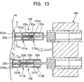
- FIG. 13 is a schematic view illustrating still another operation of the probe socket in the second embodiment
- FIG. 14 is a schematic view of the structure of a related electrical characteristic measuring device
- FIG. 15 is a schematic view of the structure of a related electrical characteristic measuring device.
- FIG. 16 is a schematic view illustrating the operation of the related electrical characteristic measuring device.
- FIG. 1 shows the structure of an electrical characteristic measuring device of a first embodiment.
- FIG. 2 shows the structure of a contact probe of the electrical characteristic measuring device shown in FIG. 1 .
- FIG. 3 is a sectional view of the main portion of the contact probe.
- an electrical characteristic measuring device 1 of a first embodiment comprises a body 2 incorporating an electrical measuring unit, a measurement cable 3 drawn out from the body 2 , and a probe socket 4 connected to the measurement cable 3 .
- the probe socket 4 has two contact probes 5 and 6 .
- the contact probes 5 and 6 have equivalent structures, so that only the contact probe 5 is shown in FIG. 2 .
- the contact probes 5 and 6 comprise probe tips 11 a and 11 b and dampers 12 a and 12 b , respectively.
- the probe tips 11 a and 11 b comprise, respectively, first barrels 21 a and 21 b , probe pins 22 a and 22 b movable forward and backward in the respective first barrels 21 a and 21 b , and first springs 23 a and 23 b for elastically biasing the respective probe pins 22 a and 22 b .
- the dampers 12 a and 12 b comprise, respectively, second barrels 31 a and 31 b , plungers 32 a and 32 b movable forward and backward in the respective second barrels 31 a and 31 b , and second springs 33 a and 33 b for elastically biasing the respective plungers 32 a and 32 b.
- the probe socket 4 may comprise the two contact probes 5 and 6 and a body 4 a for holding the contact probes 5 and 6 .
- the body 4 a has two socket portions 4 b and 4 b in which the second barrels 31 a and 31 b of the respective contact probes 5 and 6 are inserted.
- Probe terminals 4 c and 4 c are connected to the respective socket portions 4 b and 4 b , and the contact probes 5 and 6 are connected to the measurement cables 3 and 3 through the probe terminals 4 c.
- the contact probes 5 and 6 are aligned so that the forward and backward movement directions of the probe pin 22 a and those of the probe pin 22 b are the same with respect to the body 4 a, and so that first ends 21 a 1 , and 21 b 1 , of the respective first barrels 21 a and 21 b are aligned with respect to the body 4 a.
- the probe tip 11 a comprises the first barrel 21 a, the probe pin 22 a, and the first spring 23 a .
- the first barrel 21 a has a cavity 21 a 2 having a bottom.
- the cavity 21 a 2 is formed so that the bottom is formed at a second end 21 a 3 of the first barrel 21 a, and communicates with an opening 21 a 4 in the first end 21 a 1 , of the first barrel.
- a stopper 21 a 5 is disposed at the first end 21 a 1 of the first barrel 21 a.
- the probe pin 22 a is accommodated in the cavity 21 a 2 of the first barrel 21 a, and is thinner than the opening 21 a 4 .
- An engager 22 a 1 is formed at a base end of the probe pin 22 a , and is stopped by the stopper 21 a 5 as a result of engaging it with the stopper 21 a 5 .
- An end 22 a 2 of the probe pin 22 a is formed with a spherical shape.
- the first spring 23 a is accommodated in the cavity 21 a 2 .
- One end of the first spring 23 a communicates with the engager 22 a 1 of the probe pin, and the other end of the first spring 23 a communicates with an inner surface defining the cavity 21 a 2 .
- the inner surface may be the bottom formed at the second end 21 a 3 of the first barrel 21 a .
- the first spring 23 a elastically biases the probe pin 22 a towards the opening 21 a 4 .
- the probe pin 22 a is prevented from becoming dislodged from the first barrel 21 a . It is thus possible for the end 22 a 2 of the probe pin to protrude from the opening 21 a 4 , and for the probe pin 22 a to move forward and backward in the first barrel 21 a.
- the damper 12 a is mounted to the second end 21 a 3 of the first barrel 21 a and elastically supports the first barrel 21 a, and comprises the second barrel 31 a, the plunger 32 a, and the second spring 33 a.
- the second barrel 31 a has a cavity 31 a 2 having a bottom.
- the cavity 31 a 2 is formed so that the bottom is formed at a second end 31 a 3 of the second barrel 31 a, and communicates with an opening 31 a 4 in a first end 31 a 1 of the second barrel 31 a.
- a stopper 31 a 5 is disposed at the first end 31 a 1 of the second barrel 31 a.
- the side of the second end 31 a 3 of the second barrel 31 a corresponds to a socket receiver 31 a 6 .
- the socket receiver 31 a 6 is inserted in the socket portion 4 b of the probe socket 4 .
- the plunger 32 a is disposed in the cavity 31 a 2 of the second barrel 31 a , and is thinner than the opening 31 a 4 .
- An engager 32 a 1 is formed at a base end of the plunger 32 a , and is stopped by the stopper 31 a 5 as a result of engaging the stopper 31 a 5 .
- a second spring 33 a is accommodated in the cavity 31 a 2 .
- One end of the second spring 33 a communicates with the engager 32 a 1 of the plunger, and the other end of the second spring 33 a communicates with an inner surface defining the cavity 31 a 2 .
- the inner surface may be that of the bottom formed at the second end 31 a 3 of the second barrel 31 a .
- the second spring 33 a elastically biases the plunger 32 a towards the opening 31 a 4 .
- the plunger 32 a It is thus possible for an end of the plunger 32 a to protrude from the opening 31 a 4 , and for the plunger 32 a to move forward and backward in the second barrel 31 a.
- the plunger 32 a is connected to the second end 21 a 3 of the first barrel 21 a, so that the first barrel 21 a is elastically supported by the damper 12 a.
- the probe pin 22 a is formed of a material having a sheet resistivity that is greater than that of the material of the first barrel 21 a.
- An example of a specific material of the probe pin 22 a is a resin composition having carbon fiber portions mixed in a thermoplastic resin material.
- the carbon fiber portions have a thickness of 100 nm or less, and a ratio between the fiber length and the fiber thickness of 5 or more.
- the amount of carbon fiber portions mixed in the thermoplastic resin material is desirably 0.1 to 8 parts by weight with respect to 100 parts by weight of the thermoplastic resin material.
- At least one of polycarbonate, polybutylene terephthalate, polyethylene terephthalate, and polypropylene may be used for the thermoplastic resin material as matrix resin.
- the first barrel 21 a may be formed of, for example, a material comprising brass plated with gold, or other material having equivalent structural and resistivity properties.
- the sheet resistivity of the probe pin 22 a may be in the range of from 10 6 to 10 12 ⁇ / ⁇ (ohms/square), and more desirably in the range of from 10 8 to 10 10 ⁇ / ⁇ .
- Sheet resistivity of the probe pin 22 a less than 10 6 ⁇ / ⁇ results in electrical charges flowing with a high current value when the probe pin 22 a contacts the object to be measured, which may cause electrostatic discharge damage to the object.
- Sheet resistivity of the probe pin 22 a greater than 10 12 ⁇ / ⁇ may delay the escape of the electrical charges.
- a diameter R of the end 22 a 2 of the probe pin 22 a may be in the range of from 3.5 to 4 mm, and that a maximum protruding height S of the probe pin 22 a from the opening 21 a 4 may be in the range of from 0.15 to 0.25 mm. Since only the spherical portion of the end 22 a 2 of the probe pin protrudes from the opening 21 a 4 , even if the probe pin 22 a is pushed into the first barrel 21 a, the probe pin 22 a may not contact the stopper 21 a 5 , thereby making it possible to prevent wearing of the stopper 21 a 5 .
- Other probe tip shapes may be used to achieve a desired contact pressure.
- the spring constant of the second spring 33 a is greater than the spring constant of the first spring 23 a.
- the second spring 33 a may undergo a stroke on the order of 0.3 mm when it is compressed by a load of 50 g to 60 g.
- the first spring 23 a may undergo a stroke on the order of 0.3 mm when it is compressed by a load of 30 g.
- the first spring 23 a is more easily compressed than the second spring 33 a is compressed, so that the first end 21 a 1 of the first barrel 21 a comes into contact with the object to be measured subsequent to the contacting of the probe pin 22 a with the object, and, thereafter, the second spring 33 a is further compressed in order to operate the damper 12 a.
- FIGS. 4 , 5 , 6 , and 7 are schematic views for illustrating the operations of the probe socket 4 in the embodiment.
- the probe socket 4 is brought closer to a terminal unit T of a thin-film magnetic head H (as an example of the object whose characteristics are to be measured).
- the terminal unit T of the thin-film magnetic head may have two terminals T 1 and T 2 .
- Terminal surfaces T 11 and T 22 of the respective terminals T 1 and T 2 have different heights, due to manufacturing tolerances or design.
- the terminal surface T 11 is positioned closer to the probe socket 4 than the terminal surface T 22 .
- the probe socket 4 is brought even closer to the terminal unit T of the thin-film magnetic head H in order to bring the probe pin 22 a of the contact probe 5 into contact with the terminal surface T 11 .
- the probe pin 22 a and the terminal T 1 are brought into electrical conduction, so that electrical charges which may be present at the probe pin 22 a or the terminal T 1 flow through the probe pin 22 a. Since the sheet resistivity of the probe pin 22 a is relatively high, the electrical current value is kept small, thereby mitigating electrostatic discharge damage to the thin-film magnetic head H.
- the probe socket 4 is brought even closer to the terminal unit T of the thin-film magnetic head H in order to bring the probe pin 22 b of the contact probe 6 into contact with the terminal surface T 22 .
- the probe pin 22 a is pushed into the first barrel 21 a as a result of compression of the first spring 23 a when the terminal T 1 and the probe socket 4 are brought close to each other, so that the first end 21 a 1 of the first barrel 21 a contacts the terminal T 1 . Since the spring constant of the first spring 23 a is less than the spring constant of the second spring 33 a, the first spring 23 a is more easily compressed than the second spring 33 a is compressed. The motion continues until contact between probe pin 22 b and terminal T 2 occurs.
- the plunger 32 a is pushed into the second barrel 31 a as a result of compression of the second spring 33 a of the contact probe 5 , so that the contact probe 5 itself becomes shorter.
- the first spring 23 b of the contact probe 6 is compressed, so that the first end 21 b 1 of the first barrel 21 b comes into contact with the terminal surface T 22 .
- the first barrels 21 a and 21 b of the respective contact probes 5 and 6 contact the terminals T 1 and T 2 , respectively. Since the first barrels 21 a and 21 b are formed of materials having relatively small sheet resistivity, voltage drops between the terminal unit T and the contact probes 5 and 6 are reduced.
- the damper 12 a of the contact probe 5 is operated to reduce the overall length of the contact probe 5 itself.
- the first spring 23 b of the contact probe 6 is compressed, so that the first barrel 21 b can be brought into contact with the terminal surface T 22 . Therefore, it is possible to bring the first ends 21 a 1 and 21 b 1 of the first barrels into contact with the terminals T 1 and T 2 , so that electrical characteristics can be measured precisely.
- the plunger 32 a is pushed into the second barrel 31 a as a result of compression of the second spring 33 a of the contact probe 5 , it is possible to reduce contact pressure between the first barrel 21 a of the contact probe 5 and the terminal surface T 11 , so that the terminal surface T 11 will not get scratched by the first barrel 21 a.
- the first spring 23 a is more easily compressed than the second spring 33 a is compressed when the contact probe 5 is pushed against the terminal unit T, it is possible to reliably contact the first barrel 21 a with the terminal surface T 11 , so that electrical characteristics can be measured smoothly.
- FIG. 8 shows the structure of an electrical characteristic measuring device of the second embodiment.
- FIG. 9 shows the structure of a contact probe of the electrical characteristic measuring device shown in FIG. 8 .
- Corresponding parts of the electrical characteristic measuring device, a contact socket, and the contact probe to those of the electrical characteristic measuring device, the contact socket, and the contact probe having equivalent functions in the first embodiment are given the same reference numerals. Descriptions thereof will be either omitted or simplified.
- an electrical characteristic measuring device 101 comprises a body 2 , a measurement cable 3 , and a probe socket 104 .
- the probe socket 104 has two contact probes 105 and 106 .
- the contact probes 105 and 106 have equivalent structures, so that only the contact probe 105 is shown in FIG. 9 .
- the contact probes 105 and 106 comprise probe tips 111 a and 111 b and dampers 112 a and 112 b , respectively.
- the probe tips 111 a and 111 b comprise, respectively, first barrels 121 a and 121 b , probe pins 22 a and 22 b movable forward and backward in the respective first barrels 121 a and 121 b , and first springs 23 a and 23 b for elastically biasing the respective probe pins 22 a and 22 b .
- the dampers 112 a and 112 b comprise, respectively, second barrels 131 a and 131 b , plungers 132 a and 132 b movable forward and backward in the respective second barrels 131 a and 131 b , and second springs 33 a and 33 b for elastically biasing the respective plungers 132 a and 132 b.
- the probe socket 104 comprises the two contact probes 105 and 106 and a body 4 a for holding the contact probes 105 and 106 .
- the body 4 a has two socket portions 4 b and 4 b in which the plungers 132 a and 132 b of the respective contact probes 105 and 106 are inserted.
- Probe terminals 4 c are connected to the socket portions 4 b , and the contact probes 105 and 106 are connected to the measurement cables 3 through the probe terminals 4 c.
- the contact probes 105 and 106 are aligned so that the forward and backward movement directions of the probe pin 22 a and those of the probe pin 22 b are the same with respect to the body 4 a, and so that first ends 121 a 1 and 121 b 1 of the respective first barrels 121 a and 121 b are aligned with respect to the body 4 a.
- the probe tip 111 a comprises the first barrel 121 a, the probe pin 22 a, and the first spring 23 a.
- the first barrel 121 a has a cavity 121 a 2 having a bottom.
- the cavity 121 a 2 is formed so that the bottom is comprised of a partition 140 formed at a second end 121 a 3 of the first barrel 121 a, and communicates with an opening 121 a 4 at the first end 121 a 1 of the first barrel.
- a stopper 121 a 5 is disposed at the first end 121 a 1 of the first barrel 121 a.
- the probe pin 22 a is disposed in the cavity 121 a 2 of the first barrel 121 a.
- An engager 22 a 1 is formed at a base end of the probe pin 22 a , and is stopped by the stopper 121 a 5 as a result of engaging the stopper 121 a 5 .
- the first spring 23 a is disposed in the cavity 121 a 2 .
- One end of the first spring 23 a communicates with the engager 22 a 1 of the probe pin, and the other end of the first spring 23 a communicates with the partition 140 .
- the first spring 23 a elastically biases the probe pin 22 a towards the opening 121 a 4 .
- the damper 112 a is mounted to the second end 121 a 3 of the first barrel 121 a and elastically supports the first barrel 121 a , and comprises the second barrel 131 a , the plunger 132 a , and the second spring 33 a.
- the second barrel 131 a has a cavity 131 a 2 having a bottom.
- the cavity 131 a 2 is formed so that the bottom is formed at a second end 131 a 3 of the second barrel 131 a , and communicates with an opening 131 a 4 in a first end 131 a 1 of the second barrel 131 a.
- the cavities 121 a 2 and 131 a 2 of the respective first barrel 121 a and the second barrel 131 a are divided by the partition 140 .
- a stopper 131 a 5 is disposed at the first end 131 a 1 of the second barrel 131 a.
- the side of an end 132 a 3 of the plunger 132 a corresponds to a socket receiver 132 a 4 .
- the socket receiver 132 a 4 is inserted in the socket portion 4 b of the probe socket 104 .
- the plunger 132 a is disposed in the cavity 131 a 2 of the second barrel 131 a.
- An engager 132 a 1 is formed at a base end of the plunger 132 a , and is stopped by the stopper 131 a 5 as a result of engaging the stopper 131 a 5 .
- the second spring 33 a is disposed in the cavity 131 a 2 .
- One end of the second spring 33 a communicates with the engager 132 a 1 of the plunger, and the other end of the second spring 33 a communicates with the partition 140 .
- the second spring 33 a elastically biases the plunger 132 a towards the opening 131 a 4 .
- the end 132 a 3 of the plunger 132 a protrude from the opening 131 a 4 , and for the plunger 132 a to move forward and backward in the second barrel 131 a.
- the second barrel 131 a is connected to the first barrel 121 a , so that the first barrel 121 a is elastically supported by the damper 112 a.
- the probe pin 22 a may be formed of a material having a sheet resistivity that is greater than that of the material of the first barrel 121 a.
- the first barrel 121 a may be formed of the same material as the first barrel 21 a in the first embodiment.
- a diameter R of the end 22 a 2 of the probe pin 22 a , and a maximum protruding height S of the probe pin 22 a may be set at values as indicated in the first embodiment.
- the spring constant of the second spring 33 a and the spring constant of the first spring 23 a may be set at values as indicated in the first embodiment.
- the first spring 23 a is more easily compressed than the second spring 33 a is compressed, so that the first end 121 a 1 of the first barrel 121 a comes into contact with an object to be measured subsequent to the contacting of the probe pin 22 a with the object, and, thereafter, the second spring 33 a is compressed in order to operate the damper 112 a.
- FIGS. 10 , 11 , 12 , and 13 are schematic views for illustrating the operations of the probe socket 104 in the embodiment.
- the probe socket 104 is brought closer to a terminal unit T of a thin-film magnetic head H (as an example of an object whose characteristics are to be measured).
- the probe socket 104 is brought even closer to the terminal unit T of the thin-film magnetic head H in order to bring the probe pin 22 a of the contact probe 105 into contact with a terminal surface T 11 .
- the probe pin 22 a and the terminal T 1 are then brought into electrical contact, so that electrical charges which may be present at the probe pin 22 a or the terminal T 1 flow through the probe pin 22 a. Since the sheet resistivity of the probe pin 22 a is relatively high, the electrical current value is kept small, thereby mitigating electrostatic discharge damage to the thin-film magnetic head H.
- the probe socket 104 is brought even closer to the terminal unit T of the thin-film magnetic head H in order to bring the probe pin 22 b of the contact probe 106 into contact with a terminal surface T 22 .
- the probe pin 22 a is pushed into the first barrel 121 a as a result of compression of the first spring 23 a when the terminal unit T and the probe socket 104 are brought close to each other, so that the first end 121 a 1 of the first barrel 21 a contacts the terminal T 1 . Since the spring constant of the first spring 23 a is less than the spring constant of the second spring 33 a , the first spring 23 a is more easily compressed than the second spring 33 a is compressed.
- the plunger 132 a is pushed into the second barrel 131 a as a result of compression of the second spring 33 a of the contact probe 105 , so that the contact probe 105 itself becomes shorter.
- the first spring 23 b of the contact probe 106 is compressed, so that the first end 121 b 1 of the first barrel 121 b comes into contact with the terminal surface T 22 .
- the first barrels 121 a and 121 b of the respective contact probes 105 and 106 contact the terminals T 1 and T 2 , respectively. Since the first barrels 121 a and 121 b are formed of materials having relatively small sheet resistivity, voltage drops between the terminal unit T and the contact probes 105 and 106 are reduced.
- the damper 112 a of the contact probe 105 is operated to reduce the overall length of the contact probe 105 itself.
- the first spring 23 b of the contact probe 106 is compressed, so that the first barrel 121 b can be brought into contact with the terminal surface T 22 . Therefore, it is possible to bring the first ends 121 a 1 and 121 b 1 of the first barrels 121 a and 121 b into contact with the terminals T 1 and T 2 , so that electrical characteristics can be measured.
- the plunger 132 a is pushed into the second barrel 131 a as a result of compression of the second spring 33 a of the contact probe 105 , it is possible to reduce contact pressure between the first barrel 121 a of the contact probe 105 and the terminal surface T 11 , so that the terminal surface T 11 may not be scratched by the first barrel 121 a.
- the first spring 23 a is more easily compressed than the second spring 33 a is compressed when the contact probe 105 is pushed against the terminal unit T, it is possible to reliably contact the first barrel 121 a with the terminal surface T 11 , so that electrical characteristics can be measured smoothly.
- a damper elastically supporting the first barrel is mounted to the second end of the first barrel of the probe tip, so that contact pressure produced when the first end of the first barrel contacts an object to be measured is reduced by the damper, as a result of which the object may not be scratched.
Abstract
A contact probe includes a probe tip and a damper. The probe tip includes a first barrel, a probe pin, and a first spring. The first barrel has a cavity with a bottom, an opening being disposed in a first end of the first barrel and the bottom being disposed at a second end of the first barrel. The probe pin is mounted in the first barrel so as to be movable forward and backward. The first spring is mounted in the cavity for elastically biasing the probe pin towards the opening. The damper is mounted to the second end of the first barrel, and elastically supports the first barrel.
Description
This application is a divisional application of U.S. patent application Ser. No. 10/859,282, filed on Jun. 2, 2004 now U.S. Pat. No. 7,116,123, which claims priority to Japanese Patent Japanese Patent Application No. 2003-163637, filed on June 9, said applications being incorporated herein by reference.
1. Field of the Invention
Aspects of the present invention relate to a contact probe, a probe socket, an electrical characteristic measuring device, and a method for pushing the contact probe against an object to be measured. More particularly, an aspect of the present invention relates to a technology which makes it possible to mitigate electrostatic discharge damage or mechanical damage to an electronic device when measuring electrical characteristics of the electronic device.
2. Description of the Related Art
As shown in FIG. 14 , a related electrical characteristic measuring device, such as a digital multimeter, comprises a body 61 incorporating an electrical measuring unit, a measurement cable 62 drawn out from the body 61, and a probe socket 63 connected to the measurement cable 62. In the example shown in FIG. 14 , the probe socket 63 has two contact probes 64. By pushing the contact probes 64 against, for example, terminals T1 and T2 of a thin-film magnetic head H (object to be measured), an electrical characteristic between the terminals T1 and T2 can be measured.
In the related electrical characteristic measuring device shown in FIG. 14 , the measurement cable 62 may accumulate electrical charge because it has an insulating film, and the contact probes 64 are in an easily chargeable state because they are in electrically floated states from a power source ground of the body 61. When the measurement cable 62 or the contact probes 64 are charged, and the contact probes 64 contact the terminals T1 and T2 of the thin-film magnetic head H, an electrical charge Q moves momentarily. Even if the electrical charge Q that moves momentarily is a small amount, a current value, which is a time differential of the electrical charge Q, is increased. The flow of a large amount of current causes electrostatic discharge damage to the thin-film magnetic head H.
Contact probes having barrel structures are disclosed as means for preventing electrostatic discharge damage in, for example, Japanese Unexamined Patent Application Publication No. 2001-201515. Probes having the same structures as the contact probes disclosed in Japanese Unexamined Patent Application Publication No. 2001-201515 is shown in FIG. 15 . As shown in FIG. 15 , contact probes 200 have respective probe pins 201 and respective springs 202 disposed in respective barrels 203. The probe pins 201 are biased towards respective ends 203 a of the barrels by the respective springs 202. Ends of the probe pins 201 protrude from the respective barrels 203. The probe pins 201 are formed of high-resistance materials, and the barrels 203 are formed of low-resistance materials.
When the above-described contact probes are pushed against the respective terminals T1 and T2 of the thin-film magnetic head H, first, ends of the probe pins 201 come into contact with the respective terminals T1 and T2 of the thin-film magnetic head. Then, the probe pins 201 push and compress the springs 202, and are pushed into the respective barrels 203. At the same time that the probe pins 201 are pushed into the respective barrels 203, the ends 203 a of the barrels 203 come into contact with the respective terminals T1 and T2. As a result of the barrels 203 coming into contact with the respective terminals T1 and T2, an electrical circuit is formed between the thin-film magnetic head H and the electrical characteristic measuring device, and an electrical characteristic between the terminals T1 and T2 of the thin-film magnetic head H is measured.
When the ends of the respective probe pins 201 contact the respective terminals T1 and T2 of the thin-film magnetic head, electrical charges flow between the thin-film magnetic head H and the probe pins 201. Since the probe pins 201 are formed of high-resistance materials, the electrical current value at this time is low. Accordingly, since the electrical charges flow with a small current value, and are removed before the barrels 203 and 203 come into contact with their respective terminals T1 and T2, it is possible to prevent electrostatic discharge damage.
However, since the contact probes disclosed in Japanese Unexamined Patent Application Publication No. 2001-201515 are directly mounted to the probe socket, they are formed so that force applied to the probe socket is directly applied to the contact probes. Therefore, when the probe socket is strongly pushed against the terminals of the thin-film magnetic head, the ends of the barrels strongly contact the terminal surfaces, thereby producing contact pressure which may damage the terminal surfaces.
In addition, as shown in FIG. 16 , the positions of terminal surfaces T11 and T22 of the thin-film magnetic head may not be aligned because of stacking of dimensional tolerance at the time of manufacture. When one tries to measure electrical characteristics by pushing the probe socket 63 against the non-aligned terminals T1 and T2, and the barrel end 203 a of one of the contact probes 200 contacts the terminal surface T11, only the probe pin 201 of the other contact probe 200 may be in contact with the terminal surface T22. In this case, the probe pin 201 having high resistance is interposed in a measurement circuit system, thereby preventing precise measurements of the electrical characteristics.
An aspect of the present invention to provides a contact probe which makes it possible to measure electrical characteristics while preventing electrostatic discharge damage to an object to be measured, a probe socket, an electrical characteristic measuring device, and a method for pushing the contact probe against the object to be measured.
According to an aspect of the present invention, a contact probe is provided comprising a probe tip and a damper. The probe tip comprises a first barrel, a probe pin, and a first spring. The first barrel has a cavity with a bottom, an opening being disposed in a first end of the first barrel and the bottom being disposed at a second end of the first barrel. The probe pin is movable forward and backward in the cavity. The first spring is mounted in the cavity such that it elastically biases the probe pin towards the opening. The damper is mounted to the second end of the first barrel, and elastically supports the first barrel. Contact pressure produced when the first end of the first barrel contacts an object to be measured is reduced by the damper.
The contact probe may be such that the damper comprises a second barrel, a plunger, and a second spring. The second barrel has a cavity with a bottom, an opening being disposed in a first end of the second barrel and the bottom being disposed at a second end of the second barrel. The plunger is mounted in the second barrel so as to be movable forward and backward, and is connected to the second end of the first barrel. The second spring is mounted in the second barrel for elastically biasing the plunger towards the opening of the second barrel. It may be desirable that the forward and backward movement directions of the plunger and those of the probe pin be the same.
The first barrel may be elastically supported by the second spring through the plunger, so that contact pressure of the first barrel can be reduced by the second spring. In addition, making the forward and backward movement directions of the plunger and those of the probe pin the same may make it possible to reduce the contact pressure of the first barrel.
The contact probe may be such that the damper comprises a second barrel, a plunger, and a second spring. The second barrel has a cavity with a bottom, an opening being disposed in a first end of the second barrel and the bottom being disposed at a second end of the second barrel. The plunger is mounted in the second barrel so as to be movable forward and backward. The second spring is mounted in the second barrel for elastically biasing the plunger towards the opening of the second barrel. The second end of the second barrel is connected to the second end of the first barrel.
The first barrel may be elastically supported by the second spring through the second barrel, so that contact pressure of the first barrel can be reduced by the second spring. In a further aspect, integrally forming the first and second barrels makes it possible to reduce the number of components of the contact probe.
In a contact probe according to an embodiment of the present invention, the spring constant of the second spring may be greater than the spring constant of the first spring.
When the contact probe is pushed against an object to be measured, the first spring is more easily compressed than the second spring is compressed. When the first spring is compressed, the first end of the first barrel comes into contact with the object subsequent to the contacting of the probe pin. Then, the second spring is compressed, and the damper operates. Therefore, may be possible to reliably bring the first barrel into contact with the object, so that electrical characteristics can be measured.
In a contact probe according to an embodiment of the present invention, the sheet resistivity of the probe pin may be greater than the sheet resistivity of the first barrel. Since the sheet resistivity of the probe pin is greater than that of the barrel, the electrical charges at an object to be measured and the contact probe itself may move slowly through the probe pin, so that the current value resulting from the electrical charges can be kept low. Therefore, may be possible to mitigate electrostatic discharge damage to the object caused by contact of the contact probe.
In a contact probe according to an embodiment of the present invention, an end of the probe pin may be spherical. By virtue of the structure, an object to be measured will not be scratched by contact of the probe pin.
According to another aspect of the present invention, there is provided a probe socket comprising a plurality of any one of the above-described contact probes. In the probe socket, the forward movement directions of the contact pins of the contact probes may be the same and the backward movement directions of the contact pins of the contact probes may be the same, and the first ends of the first barrels may be aligned. Since the ends of the first barrels contact an object to be measured at the approximately same time, electrical characteristics can be measured effectively.
In a circumstance where the measurement surfaces of the object to be measured are not aligned, and only the first barrels of some of the contact probes are in contact with respective measurement surfaces of the object (so that the first barrels of the other contact probes are not in contact with respective measurement surfaces of the object), the dampers of the contact probes whose first barrels are in contact may operate to reduce the overall length of the contact probes themselves by the action of further pushing the probe socket against the object. Accordingly, the first springs of the contact probes whose first barrels are not in contact are compressed, so that the first barrels can be brought into contact with the respective measurement surfaces of the object. Therefore, it is possible to bring the first barrels of all contact probes into contact with the object, so that electrical characteristics can be measured precisely.
According to a yet another aspect of the present invention, there is provided an electrical characteristic measuring device comprising any one of the above-described contact probes, or the above-described probe socket.
According to a still another aspect of the present invention, there is provided a method for pushing a contact probe against a terminal of an electronic device. The method comprises the steps of bringing an end of a probe pin into contact with the terminal, bringing a first end of a first barrel into contact with the terminal while compressing a first spring, and operating a damper. The contact probe comprises a probe tip and the damper. The probe tip comprises the first barrel, the probe pin, and the first spring. The first barrel has a cavity with a bottom, an opening being disposed in the first end of the first barrel and the bottom being disposed at a second end of the first barrel. The probe pin is movable forward and backward in the cavity. The first spring is mounted in the cavity for elastically biasing the probe pin towards the opening. The damper is mounted to the second end of the first barrel, and elastically supports the first barrel.
According to a method of the present invention, the damper may comprise a second barrel, a plunger, and a second spring. The second barrel has a cavity with a bottom, an opening may be disposed in a first end of the second barrel and the bottom is disposed at a second end of the second barrel, the plunger may be mounted in the second barrel so as to be movable forward and backward, and the second spring is mounted in the second barrel for elastically biasing the plunger towards the opening of the second barrel. In addition, the step of operating the damper may comprise compressing the second spring and biasing the plunger towards the second end of the second barrel.
According to the above-described method, when the contact probe is pushed against an object to be measured, the first spring is more easily compressed than the second spring is compressed. Then, the first end of the first barrel comes into contact with the object subsequent to the contacting of the probe pin. Then, the second spring is compressed, and the damper operates. Therefore, it is possible to reliably bring the first barrel into contact with the object, so that electrical characteristics can be measured.
Several embodiments of the present invention will be described with reference to the relevant drawings. FIG. 1 shows the structure of an electrical characteristic measuring device of a first embodiment. FIG. 2 shows the structure of a contact probe of the electrical characteristic measuring device shown in FIG. 1 . FIG. 3 is a sectional view of the main portion of the contact probe.
As shown in FIG. 1 , an electrical characteristic measuring device 1 of a first embodiment comprises a body 2 incorporating an electrical measuring unit, a measurement cable 3 drawn out from the body 2, and a probe socket 4 connected to the measurement cable 3. In the example shown in FIG. 1 , the probe socket 4 has two contact probes 5 and 6. By pushing the contact probes 5 and 6 against, for example, terminals of a thin-film magnetic head (as an example of the object whose characteristics are to be measured), electrical characteristics between the terminals can be measured.
The contact probes 5 and 6 have equivalent structures, so that only the contact probe 5 is shown in FIG. 2 . As shown in FIGS. 1 and 2 , the contact probes 5 and 6 comprise probe tips 11 a and 11 b and dampers 12 aand 12 b, respectively. The probe tips 11 a and 11 b comprise, respectively, first barrels 21 a and 21 b, probe pins 22 a and 22 b movable forward and backward in the respective first barrels 21 a and 21 b, and first springs 23 a and 23 b for elastically biasing the respective probe pins 22 a and 22 b. The dampers 12 a and 12 b comprise, respectively, second barrels 31 a and 31 b, plungers 32 a and 32 b movable forward and backward in the respective second barrels 31 a and 31 b, and second springs 33 a and 33 b for elastically biasing the respective plungers 32 a and 32 b.
As shown in FIG. 1 , the probe socket 4 may comprise the two contact probes 5 and 6 and a body 4 a for holding the contact probes 5 and 6. The body 4 a has two socket portions 4 b and 4 b in which the second barrels 31 a and 31 b of the respective contact probes 5 and 6 are inserted. Probe terminals 4 c and 4 c are connected to the respective socket portions 4 b and 4 b, and the contact probes 5 and 6 are connected to the measurement cables 3 and 3 through the probe terminals 4 c.
The contact probes 5 and 6 are aligned so that the forward and backward movement directions of the probe pin 22 a and those of the probe pin 22 b are the same with respect to the body 4 a, and so that first ends 21 a 1, and 21 b 1, of the respective first barrels 21 a and 21 b are aligned with respect to the body 4 a.
As shown in FIG. 2 , the probe tip 11 a comprises the first barrel 21 a, the probe pin 22 a, and the first spring 23 a. The first barrel 21 a has a cavity 21 a 2 having a bottom. The cavity 21 a 2 is formed so that the bottom is formed at a second end 21 a 3 of the first barrel 21 a, and communicates with an opening 21 a 4 in the first end 21 a 1, of the first barrel. A stopper 21 a 5 is disposed at the first end 21 a 1 of the first barrel 21 a.
The probe pin 22 a is accommodated in the cavity 21 a 2 of the first barrel 21 a, and is thinner than the opening 21 a 4. An engager 22 a 1 is formed at a base end of the probe pin 22 a, and is stopped by the stopper 21 a 5 as a result of engaging it with the stopper 21 a 5. An end 22 a 2 of the probe pin 22 a is formed with a spherical shape.
The first spring 23 a is accommodated in the cavity 21 a 2. One end of the first spring 23 a communicates with the engager 22 a 1 of the probe pin, and the other end of the first spring 23 a communicates with an inner surface defining the cavity 21 a 2. The inner surface may be the bottom formed at the second end 21 a 3 of the first barrel 21 a. The first spring 23 a elastically biases the probe pin 22 a towards the opening 21 a 4. By stopping the engager 22 a 1 of the probe pin 22 a by the stopper 21 a 5 as a result of engaging it with the stopper 21 a 5, the probe pin 22 a is prevented from becoming dislodged from the first barrel 21 a. It is thus possible for the end 22 a 2 of the probe pin to protrude from the opening 21 a 4, and for the probe pin 22 a to move forward and backward in the first barrel 21 a.
The damper 12 a is mounted to the second end 21 a 3 of the first barrel 21 a and elastically supports the first barrel 21 a, and comprises the second barrel 31 a, the plunger 32 a, and the second spring 33 a. The second barrel 31 a has a cavity 31 a 2 having a bottom. The cavity 31 a 2 is formed so that the bottom is formed at a second end 31 a 3 of the second barrel 31 a, and communicates with an opening 31 a 4 in a first end 31 a 1 of the second barrel 31 a. A stopper 31 a 5 is disposed at the first end 31 a 1 of the second barrel 31 a. The side of the second end 31 a 3 of the second barrel 31 a corresponds to a socket receiver 31 a 6. The socket receiver 31 a 6 is inserted in the socket portion 4 b of the probe socket 4.
The plunger 32 a is disposed in the cavity 31 a 2 of the second barrel 31 a, and is thinner than the opening 31 a 4. An engager 32 a 1 is formed at a base end of the plunger 32 a, and is stopped by the stopper 31 a 5 as a result of engaging the stopper 31 a 5. A second spring 33 a is accommodated in the cavity 31 a 2. One end of the second spring 33 a communicates with the engager 32 a 1 of the plunger, and the other end of the second spring 33 a communicates with an inner surface defining the cavity 31 a 2. The inner surface may be that of the bottom formed at the second end 31 a 3 of the second barrel 31 a. The second spring 33 a elastically biases the plunger 32 a towards the opening 31 a 4. By stopping the engager 32 a 1 of the plunger by the stopper 31 a 5 as a result of engaging it with the stopper 31 a 5, the plunger 32 a is prevented from becoming dislodged from the second barrel 31 a. The forward and backward movement directions of the plunger 32 a follow those of the probe pin 22 a.
It is thus possible for an end of the plunger 32 a to protrude from the opening 31 a 4, and for the plunger 32 a to move forward and backward in the second barrel 31 a. In addition, the plunger 32 a is connected to the second end 21 a 3 of the first barrel 21 a, so that the first barrel 21 a is elastically supported by the damper 12 a.
The probe pin 22 a is formed of a material having a sheet resistivity that is greater than that of the material of the first barrel 21 a. An example of a specific material of the probe pin 22 a is a resin composition having carbon fiber portions mixed in a thermoplastic resin material. The carbon fiber portions have a thickness of 100 nm or less, and a ratio between the fiber length and the fiber thickness of 5 or more. The amount of carbon fiber portions mixed in the thermoplastic resin material is desirably 0.1 to 8 parts by weight with respect to 100 parts by weight of the thermoplastic resin material. At least one of polycarbonate, polybutylene terephthalate, polyethylene terephthalate, and polypropylene may be used for the thermoplastic resin material as matrix resin.
The first barrel 21 a may be formed of, for example, a material comprising brass plated with gold, or other material having equivalent structural and resistivity properties.
The sheet resistivity of the probe pin 22 a may be in the range of from 106 to 1012 Ω/□ (ohms/square), and more desirably in the range of from 108 to 1010 Ω/□.
Sheet resistivity of the probe pin 22 a less than 106 Ω/□ results in electrical charges flowing with a high current value when the probe pin 22 a contacts the object to be measured, which may cause electrostatic discharge damage to the object. Sheet resistivity of the probe pin 22 a greater than 1012 Ω/□ may delay the escape of the electrical charges.
As shown in FIG. 3 , it may be desirable that a diameter R of the end 22 a 2 of the probe pin 22 a may be in the range of from 3.5 to 4 mm, and that a maximum protruding height S of the probe pin 22 a from the opening 21 a 4 may be in the range of from 0.15 to 0.25 mm. Since only the spherical portion of the end 22 a 2 of the probe pin protrudes from the opening 21 a 4, even if the probe pin 22 a is pushed into the first barrel 21 a, the probe pin 22 a may not contact the stopper 21 a 5, thereby making it possible to prevent wearing of the stopper 21 a 5. Other probe tip shapes may be used to achieve a desired contact pressure.
The spring constant of the second spring 33 a is greater than the spring constant of the first spring 23 a. The second spring 33 a may undergo a stroke on the order of 0.3 mm when it is compressed by a load of 50 g to 60 g. In contrast, the first spring 23 a may undergo a stroke on the order of 0.3 mm when it is compressed by a load of 30 g. By setting the spring constants of the springs 23 a and 33 a as such, the first spring 23 a is more easily compressed than the second spring 33 a is compressed, so that the first end 21 a 1 of the first barrel 21 a comes into contact with the object to be measured subsequent to the contacting of the probe pin 22 a with the object, and, thereafter, the second spring 33 a is further compressed in order to operate the damper 12 a.
Next, the operations of the contact probes 5 and 6, and the probe socket 4 in the embodiment will be described. FIGS. 4 , 5, 6, and 7 are schematic views for illustrating the operations of the probe socket 4 in the embodiment.
First, as shown in FIG. 4 , the probe socket 4 is brought closer to a terminal unit T of a thin-film magnetic head H (as an example of the object whose characteristics are to be measured). The terminal unit T of the thin-film magnetic head may have two terminals T1 and T2. Terminal surfaces T11 and T22 of the respective terminals T1 and T2 have different heights, due to manufacturing tolerances or design. In the example of FIG. 4 , the terminal surface T11 is positioned closer to the probe socket 4 than the terminal surface T22.
As shown in FIG. 5 , the probe socket 4 is brought even closer to the terminal unit T of the thin-film magnetic head H in order to bring the probe pin 22 a of the contact probe 5 into contact with the terminal surface T11. Here, the probe pin 22 a and the terminal T1 are brought into electrical conduction, so that electrical charges which may be present at the probe pin 22 a or the terminal T1 flow through the probe pin 22 a. Since the sheet resistivity of the probe pin 22 a is relatively high, the electrical current value is kept small, thereby mitigating electrostatic discharge damage to the thin-film magnetic head H.
As shown in FIG. 6 , the probe socket 4 is brought even closer to the terminal unit T of the thin-film magnetic head H in order to bring the probe pin 22 b of the contact probe 6 into contact with the terminal surface T22. At this time, in the contact probe 5, the probe pin 22 a is pushed into the first barrel 21 a as a result of compression of the first spring 23 a when the terminal T1 and the probe socket 4 are brought close to each other, so that the first end 21 a 1 of the first barrel 21 a contacts the terminal T1. Since the spring constant of the first spring 23 a is less than the spring constant of the second spring 33 a, the first spring 23 a is more easily compressed than the second spring 33 a is compressed. The motion continues until contact between probe pin 22 b and terminal T2 occurs.
Electrical conduction is achieved between the probe pin 22 b and the terminal T2, so that electrical charges which may be present at the probe pin 22 b or the terminal T2 flow through the probe pin 22 b, which may mitigate electrostatic discharge damage to the thin-film magnetic head H.
Next, as shown in FIG. 7 , when the probe socket 4 continues to be brought still closer to the terminal unit T of the thin-film magnetic head H, the plunger 32 a is pushed into the second barrel 31 a as a result of compression of the second spring 33 a of the contact probe 5, so that the contact probe 5 itself becomes shorter. At the same time, the first spring 23 b of the contact probe 6 is compressed, so that the first end 21 b 1 of the first barrel 21 b comes into contact with the terminal surface T22. Accordingly, the first barrels 21 a and 21 b of the respective contact probes 5 and 6 contact the terminals T1 and T2, respectively. Since the first barrels 21 a and 21 b are formed of materials having relatively small sheet resistivity, voltage drops between the terminal unit T and the contact probes 5 and 6 are reduced.
When the terminal surfaces T11 and T22 are not aligned, and the first barrel 21 a of the contact probe 5 is only in contact with the terminal surface T11 (so that the first barrel 21 b of the contact probe 6 is not in contact with the terminal surface T22), by further pushing the probe socket 4 against the thin-film magnetic head H, the damper 12 a of the contact probe 5 is operated to reduce the overall length of the contact probe 5 itself. By this, the first spring 23 b of the contact probe 6 is compressed, so that the first barrel 21 b can be brought into contact with the terminal surface T22. Therefore, it is possible to bring the first ends 21 a 1 and 21 b 1 of the first barrels into contact with the terminals T1 and T2, so that electrical characteristics can be measured precisely.
Since, as the probe socket 4 is moved closer to the terminal unit T of the thin-film magnetic head H, the plunger 32 a is pushed into the second barrel 31 a as a result of compression of the second spring 33 a of the contact probe 5, it is possible to reduce contact pressure between the first barrel 21 a of the contact probe 5 and the terminal surface T11, so that the terminal surface T11 will not get scratched by the first barrel 21 a.
Since, as described above, the first spring 23 a is more easily compressed than the second spring 33 a is compressed when the contact probe 5 is pushed against the terminal unit T, it is possible to reliably contact the first barrel 21 a with the terminal surface T11, so that electrical characteristics can be measured smoothly.
A second embodiment of the present invention will be described with reference to the relevant drawings. FIG. 8 shows the structure of an electrical characteristic measuring device of the second embodiment. FIG. 9 shows the structure of a contact probe of the electrical characteristic measuring device shown in FIG. 8 . Corresponding parts of the electrical characteristic measuring device, a contact socket, and the contact probe to those of the electrical characteristic measuring device, the contact socket, and the contact probe having equivalent functions in the first embodiment are given the same reference numerals. Descriptions thereof will be either omitted or simplified.
As shown in FIG. 8 , an electrical characteristic measuring device 101 comprises a body 2, a measurement cable 3, and a probe socket 104. In the example shown in FIG. 8 , the probe socket 104 has two contact probes 105 and 106.
The contact probes 105 and 106 have equivalent structures, so that only the contact probe 105 is shown in FIG. 9 . As shown in FIGS. 8 and 9 , the contact probes 105 and 106 comprise probe tips 111 a and 111 b and dampers 112 a and 112 b, respectively. The probe tips 111 a and 111 b comprise, respectively, first barrels 121 a and 121 b, probe pins 22 a and 22 b movable forward and backward in the respective first barrels 121 a and 121 b, and first springs 23 a and 23 b for elastically biasing the respective probe pins 22 a and 22 b. The dampers 112 a and 112 b comprise, respectively, second barrels 131 a and 131 b, plungers 132 a and 132 b movable forward and backward in the respective second barrels 131 a and 131 b, and second springs 33 a and 33 b for elastically biasing the respective plungers 132 a and 132 b.
As shown in FIG. 8 , the probe socket 104 comprises the two contact probes 105 and 106 and a body 4 a for holding the contact probes 105 and 106. The body 4 a has two socket portions 4 b and 4 b in which the plungers 132 a and 132 b of the respective contact probes 105 and 106 are inserted. Probe terminals 4 c are connected to the socket portions 4 b, and the contact probes 105 and 106 are connected to the measurement cables 3 through the probe terminals 4 c.
The contact probes 105 and 106 are aligned so that the forward and backward movement directions of the probe pin 22 a and those of the probe pin 22 b are the same with respect to the body 4 a, and so that first ends 121 a 1 and 121 b 1 of the respective first barrels 121 a and 121 b are aligned with respect to the body 4 a.
As shown in FIG. 9 , the probe tip 111 a comprises the first barrel 121 a, the probe pin 22 a, and the first spring 23 a. The first barrel 121 a has a cavity 121 a 2 having a bottom. The cavity 121 a 2 is formed so that the bottom is comprised of a partition 140 formed at a second end 121 a 3 of the first barrel 121 a, and communicates with an opening 121 a 4 at the first end 121 a 1 of the first barrel. A stopper 121 a 5 is disposed at the first end 121 a 1 of the first barrel 121 a.
The probe pin 22 a is disposed in the cavity 121 a 2 of the first barrel 121 a. An engager 22 a 1 is formed at a base end of the probe pin 22 a, and is stopped by the stopper 121 a 5 as a result of engaging the stopper 121 a 5.
The first spring 23 a is disposed in the cavity 121 a 2. One end of the first spring 23 a communicates with the engager 22 a 1 of the probe pin, and the other end of the first spring 23 a communicates with the partition 140. The first spring 23 a elastically biases the probe pin 22 a towards the opening 121 a 4. By virtue of the structure, it is possible for an end 22 a 2 of the probe pin to protrude from the opening 121 a 4, and for the probe pin 22 a to move forward and backward in the first barrel 121 a.
The damper 112 a is mounted to the second end 121 a 3 of the first barrel 121 a and elastically supports the first barrel 121 a, and comprises the second barrel 131 a, the plunger 132 a, and the second spring 33 a. The second barrel 131 a has a cavity 131 a 2 having a bottom. The cavity 131 a 2 is formed so that the bottom is formed at a second end 131 a 3 of the second barrel 131 a, and communicates with an opening 131 a 4 in a first end 131 a 1 of the second barrel 131 a. The cavities 121 a 2 and 131 a 2 of the respective first barrel 121 a and the second barrel 131 a are divided by the partition 140.
A stopper 131 a 5 is disposed at the first end 131 a 1 of the second barrel 131 a. The side of an end 132 a 3 of the plunger 132 a corresponds to a socket receiver 132 a 4. The socket receiver 132 a 4 is inserted in the socket portion 4 b of the probe socket 104.
The plunger 132 a is disposed in the cavity 131 a 2 of the second barrel 131 a. An engager 132 a 1 is formed at a base end of the plunger 132 a, and is stopped by the stopper 131 a 5 as a result of engaging the stopper 131 a 5. The second spring 33 a is disposed in the cavity 131 a 2. One end of the second spring 33 a communicates with the engager 132 a 1 of the plunger, and the other end of the second spring 33 a communicates with the partition 140. The second spring 33 a elastically biases the plunger 132 a towards the opening 131 a 4. By stopping the engager 132 a 1 of the plunger by the stopper 131 a 5 as a result of engaging it with the stopper 131 a 5, the plunger 132 a is prevented from becoming dislodged from the second barrel 131 a.
By virtue of the structure, it is possible for the end 132 a 3 of the plunger 132 a to protrude from the opening 131 a 4, and for the plunger 132 a to move forward and backward in the second barrel 131 a. In addition, the second barrel 131 a is connected to the first barrel 121 a, so that the first barrel 121 a is elastically supported by the damper 112 a.
As in the first embodiment, the probe pin 22 a may be formed of a material having a sheet resistivity that is greater than that of the material of the first barrel 121 a. The first barrel 121 a may be formed of the same material as the first barrel 21 a in the first embodiment.
A diameter R of the end 22 a 2 of the probe pin 22 a, and a maximum protruding height S of the probe pin 22 a may be set at values as indicated in the first embodiment. By virtue of the structure, it possible to prevent wearing of the stopper 121 a 5 caused by the probe pin 22 a.
The spring constant of the second spring 33 a and the spring constant of the first spring 23 a may be set at values as indicated in the first embodiment. The first spring 23 a is more easily compressed than the second spring 33 a is compressed, so that the first end 121 a 1 of the first barrel 121 a comes into contact with an object to be measured subsequent to the contacting of the probe pin 22 a with the object, and, thereafter, the second spring 33 a is compressed in order to operate the damper 112 a.
Next, the operations of the contact probes 105 and 106, and the probe socket 104 in the embodiment will be described. FIGS. 10 , 11, 12, and 13 are schematic views for illustrating the operations of the probe socket 104 in the embodiment.
First, as shown in FIG. 10 , the probe socket 104 is brought closer to a terminal unit T of a thin-film magnetic head H (as an example of an object whose characteristics are to be measured). Next, as shown in FIG. 11 , the probe socket 104 is brought even closer to the terminal unit T of the thin-film magnetic head H in order to bring the probe pin 22 a of the contact probe 105 into contact with a terminal surface T11. The probe pin 22 a and the terminal T1 are then brought into electrical contact, so that electrical charges which may be present at the probe pin 22 a or the terminal T1 flow through the probe pin 22 a. Since the sheet resistivity of the probe pin 22 a is relatively high, the electrical current value is kept small, thereby mitigating electrostatic discharge damage to the thin-film magnetic head H.
Next, as shown in FIG. 12 , the probe socket 104 is brought even closer to the terminal unit T of the thin-film magnetic head H in order to bring the probe pin 22 b of the contact probe 106 into contact with a terminal surface T22. At this time, in the contact probe 105, the probe pin 22 a is pushed into the first barrel 121 a as a result of compression of the first spring 23 a when the terminal unit T and the probe socket 104 are brought close to each other, so that the first end 121 a 1 of the first barrel 21 a contacts the terminal T1. Since the spring constant of the first spring 23 a is less than the spring constant of the second spring 33 a, the first spring 23 a is more easily compressed than the second spring 33 a is compressed.
Electrical conduction is achieved between the probe pin 22 b and the terminal T2, so that electrical charges which may be present at the probe pin 22 b or the terminal T2 flow through the probe pin 22 b, thereby mitigating electrostatic discharge damage to the thin-film magnetic head H.
Next, as shown in FIG. 13 , when the probe socket 104 is brought even closer to the terminal unit T of the thin-film magnetic head H, the plunger 132 a is pushed into the second barrel 131 a as a result of compression of the second spring 33 a of the contact probe 105, so that the contact probe 105 itself becomes shorter. At the same time, the first spring 23 b of the contact probe 106 is compressed, so that the first end 121 b 1 of the first barrel 121 b comes into contact with the terminal surface T22. Accordingly, the first barrels 121 a and 121 b of the respective contact probes 105 and 106 contact the terminals T1 and T2, respectively. Since the first barrels 121 a and 121 b are formed of materials having relatively small sheet resistivity, voltage drops between the terminal unit T and the contact probes 105 and 106 are reduced.
When the terminal surfaces T11 and T22 are not aligned, and the first barrel 121 a of the contact probe 105 is only in contact with the terminal surface T11 (so that the first barrel 121 b of the contact probe 106 is not in contact with the terminal surface T22), by further pushing the probe socket 104 against the thin-film magnetic head H, the damper 112 a of the contact probe 105 is operated to reduce the overall length of the contact probe 105 itself. By this, the first spring 23 b of the contact probe 106 is compressed, so that the first barrel 121 b can be brought into contact with the terminal surface T22. Therefore, it is possible to bring the first ends 121 a 1 and 121 b 1 of the first barrels 121 a and 121 b into contact with the terminals T1 and T2, so that electrical characteristics can be measured.
Since, as the probe socket 104 is moved closer to the terminal unit T of the thin-film magnetic head H, the plunger 132 a is pushed into the second barrel 131 a as a result of compression of the second spring 33 a of the contact probe 105, it is possible to reduce contact pressure between the first barrel 121 a of the contact probe 105 and the terminal surface T11, so that the terminal surface T11 may not be scratched by the first barrel 121 a.
Since, as described above, the first spring 23 a is more easily compressed than the second spring 33 a is compressed when the contact probe 105 is pushed against the terminal unit T, it is possible to reliably contact the first barrel 121 a with the terminal surface T11 , so that electrical characteristics can be measured smoothly.
The scope of the present invention is not limited to the above-described embodiments, so that various modifications may be made within the scope of the present invention. For example, although, in each of the above-described embodiments, a probe socket having two contact probes is explained, a contact socket having three or more contact probes may also be used in the present invention.
Although the description of the contact probe has been described in the context where a fist probe contacts a first corresponding terminal prior to a second probe contacting a second corresponding terminal due to a linear offset in the distances to be traversed between the probes and the terminals, such a situation may also result from an angular offset of the probe socket from the surface to which the terminals are mounted, or a combination of the two situations.
As can be further understood from the foregoing description, in the contact probe in the present invention, a damper elastically supporting the first barrel is mounted to the second end of the first barrel of the probe tip, so that contact pressure produced when the first end of the first barrel contacts an object to be measured is reduced by the damper, as a result of which the object may not be scratched.
Claims (2)
1. A method for making contact between a contact probe and a terminal of an electronic device, the method comprising:
bringing an end of a probe pin into contact with the terminal;
bringing a first end of a first barrel into contact with the terminal while compressing a first spring, wherein the first barrel has a cavity with a bottom, an opening being disposed in the first end of the first barrel and the bottom being disposed at a second end of the first barrel, wherein the first spring is mounted in the cavity for elastically biasing the probe pin towards the opening;
compressing a damper that is mounted to a second end of the first barrel and that elastically supports the first barrel, wherein the contact probe comprises a probe tip and the damper, the probe tip comprising the first barrel, the probe pin, and the first spring, the probe pin being movable forward and backward within the cavity;
wherein the damper comprises a second barrel, a plunger, and a second spring, the second barrel has a cavity with a bottom, an opening is disposed in a first end of the second barrel and the bottom is disposed at a second end of the second barrel, the plunger is mounted in the second barrel so as to be movable forward and backward, and the second spring is mounted in the second barrel for elastically biasing the plunger towards the opening of the second barrel; and
operating the damper comprises compressing the second spring and biasing the plunger towards the second end of the second barrel.
2. A method for making contact between a contact probe and a terminal of an electronic device, the method comprising:
bringing an end of a probe pin into contact with the terminal;
bringing a first end of a first barrel into contact with the terminal while compressing a first spring, wherein the first barrel has a cavity with a bottom, an opening being disposed in the first end of the first barrel and the bottom being disposed at a second end of the first barrel, wherein the first spring is mounted in the cavity for elastically biasing the probe pin towards the opening; and
compressing a damper that is mounted to a second end of the first barrel and that elastically supports the first barrel, wherein the contact probe comprises a probe tip and the damper, the probe tip comprising the first barrel, the probe pin, and the first spring, the probe pin being movable forward and backward within the cavity;
wherein, the damper further comprises a second barrel, a plunger, and a second spring, the second barrel has a cavity with a second bottom, an opening is disposed in a first end of the second barrel and the second bottom is disposed at a second end of the second barrel, wherein the plunger is mounted in the second barrel so as to be movable forward and backward, the second spring is mounted in the second barrel for elastically biasing the plunger towards the opening of the second barrel, and the second end of the second barrel is connected to the second end of the first barrel.
Priority Applications (1)
| Application Number | Priority Date | Filing Date | Title |
|---|---|---|---|
| US11/474,873 US7463045B2 (en) | 2003-06-09 | 2006-06-26 | Method for pushing a contact probe against object to be measured |
Applications Claiming Priority (4)
| Application Number | Priority Date | Filing Date | Title |
|---|---|---|---|
| JP2003-163637 | 2003-06-09 | ||
| JP2003163637A JP3981042B2 (en) | 2003-06-09 | 2003-06-09 | Contact probe, probe socket, electrical characteristic measuring apparatus, and contact probe pressing method |
| US10/859,282 US7116123B2 (en) | 2003-06-09 | 2004-06-02 | Contact probe, probe socket, electrical characteristic measuring device, and method for pushing the contact probe against object to be measured |
| US11/474,873 US7463045B2 (en) | 2003-06-09 | 2006-06-26 | Method for pushing a contact probe against object to be measured |
Related Parent Applications (1)
| Application Number | Title | Priority Date | Filing Date |
|---|---|---|---|
| US10/859,282 Division US7116123B2 (en) | 2003-06-09 | 2004-06-02 | Contact probe, probe socket, electrical characteristic measuring device, and method for pushing the contact probe against object to be measured |
Publications (2)
| Publication Number | Publication Date |
|---|---|
| US20060238213A1 US20060238213A1 (en) | 2006-10-26 |
| US7463045B2 true US7463045B2 (en) | 2008-12-09 |
Family
ID=33296784
Family Applications (3)
| Application Number | Title | Priority Date | Filing Date |
|---|---|---|---|
| US10/859,282 Expired - Fee Related US7116123B2 (en) | 2003-06-09 | 2004-06-02 | Contact probe, probe socket, electrical characteristic measuring device, and method for pushing the contact probe against object to be measured |
| US11/474,873 Expired - Fee Related US7463045B2 (en) | 2003-06-09 | 2006-06-26 | Method for pushing a contact probe against object to be measured |
| US11/504,360 Expired - Fee Related US7288952B2 (en) | 2003-06-09 | 2006-08-14 | Contact probe, probe socket, electrical characteristic measuring device, and method for pushing the contact probe against object to be measured |
Family Applications Before (1)
| Application Number | Title | Priority Date | Filing Date |
|---|---|---|---|
| US10/859,282 Expired - Fee Related US7116123B2 (en) | 2003-06-09 | 2004-06-02 | Contact probe, probe socket, electrical characteristic measuring device, and method for pushing the contact probe against object to be measured |
Family Applications After (1)
| Application Number | Title | Priority Date | Filing Date |
|---|---|---|---|
| US11/504,360 Expired - Fee Related US7288952B2 (en) | 2003-06-09 | 2006-08-14 | Contact probe, probe socket, electrical characteristic measuring device, and method for pushing the contact probe against object to be measured |
Country Status (5)
| Country | Link |
|---|---|
| US (3) | US7116123B2 (en) |
| EP (1) | EP1486789B1 (en) |
| JP (1) | JP3981042B2 (en) |
| CN (1) | CN1278125C (en) |
| DE (1) | DE602004015367D1 (en) |
Families Citing this family (22)
| Publication number | Priority date | Publication date | Assignee | Title |
|---|---|---|---|---|
| JP3981042B2 (en) * | 2003-06-09 | 2007-09-26 | アルプス電気株式会社 | Contact probe, probe socket, electrical characteristic measuring apparatus, and contact probe pressing method |
| CN100339714C (en) * | 2004-05-20 | 2007-09-26 | 华硕电脑股份有限公司 | Test probe |
| DE102004040886A1 (en) * | 2004-08-24 | 2006-03-02 | Volkswagen Ag | Operating device for a motor vehicle |
| US8410948B2 (en) * | 2008-05-12 | 2013-04-02 | John Vander Horst | Recreational vehicle holding tank sensor probe |
| CN101644733B (en) * | 2008-08-06 | 2011-07-27 | 燿华电子股份有限公司 | Fixture for testing precise printed circuit board |
| US8988090B2 (en) * | 2009-04-21 | 2015-03-24 | Johnstech International Corporation | Electrically conductive kelvin contacts for microcircuit tester |
| US9329204B2 (en) | 2009-04-21 | 2016-05-03 | Johnstech International Corporation | Electrically conductive Kelvin contacts for microcircuit tester |
| MY154684A (en) * | 2010-10-22 | 2015-07-15 | Kow Kek Hing | Test pin assembly with electrostatic discharge (esd) protection |
| KR20120104812A (en) * | 2011-03-14 | 2012-09-24 | 삼성전자주식회사 | Semiconductor wafer testing system and method |
| JP2013000986A (en) * | 2011-06-17 | 2013-01-07 | Brother Industries Ltd | Inkjet printer |
| US8963571B2 (en) * | 2011-08-24 | 2015-02-24 | Shenzhen China Star Optoelectronics Technology Co., Ltd. | Inspection device for glass substrate |
| US9128121B2 (en) * | 2012-09-28 | 2015-09-08 | Intel Corporation | Mechanism for facilitating a dynamic electro-mechanical interconnect having a cavity for embedding electrical components and isolating electrical paths |
| US9674943B2 (en) * | 2012-12-06 | 2017-06-06 | Intel Corporation | Actuation mechanisms for electrical interconnections |
| US10012686B2 (en) * | 2016-08-15 | 2018-07-03 | Tektronix, Inc. | High frequency time domain reflectometry probing system |
| CN106707565A (en) * | 2016-11-28 | 2017-05-24 | 深圳市华星光电技术有限公司 | Probe component |
| JPWO2018105444A1 (en) * | 2016-12-08 | 2019-07-25 | 三菱電機株式会社 | Probe pin |
| CN108020749B (en) * | 2018-02-06 | 2024-02-09 | 辽东学院 | Multi-pin plug checking device |
| DE102018120480B4 (en) * | 2018-08-22 | 2022-04-28 | Te Connectivity Germany Gmbh | Contact device and system |
| CN109142931B (en) * | 2018-09-03 | 2021-11-23 | 苏州华兴源创科技股份有限公司 | System and method for testing piezoelectric ceramics |
| KR102158735B1 (en) * | 2019-02-15 | 2020-09-22 | 피닉슨컨트롤스 주식회사 | Probe device of floating structure |
| US11051436B2 (en) * | 2019-12-27 | 2021-06-29 | Intel Corporation | Modular printed circuit board separation tool |
| CN113427403B (en) * | 2021-08-12 | 2022-11-01 | 北京大学口腔医学院 | Water jet cutting device |
Citations (20)
| Publication number | Priority date | Publication date | Assignee | Title |
|---|---|---|---|---|
| US3584300A (en) | 1968-07-31 | 1971-06-08 | Bendix Corp | Platen-patch board assembly with spring biased electrical contact means to effect electrical test on an electrical circuit card |
| US3904960A (en) | 1973-04-11 | 1975-09-09 | Scripps Co E W | Extendable and retractable moisture sensing probe |
| US4004843A (en) | 1975-09-25 | 1977-01-25 | Westinghouse Electric Corporation | Probe pin |
| US4490593A (en) | 1983-05-09 | 1984-12-25 | Square D Company | Arrangement for arc transfer in high amperage molded case circuit breaker |
| US4659987A (en) | 1985-03-25 | 1987-04-21 | Qa Technology Company | Electrical circuit test probe and connector |
| EP0233756A1 (en) | 1986-02-15 | 1987-08-26 | H.E.M.E. International Limited | Current probe |
| EP0290182A1 (en) | 1987-05-06 | 1988-11-09 | Hewlett-Packard Company | High frequency passive probe |
| US4889483A (en) | 1984-09-06 | 1989-12-26 | Granco-Clark, Inc. | Temperature controlled probe assembly |
| US4918384A (en) | 1987-06-10 | 1990-04-17 | Feinmetall Gmbh | Spring contact pin for testing an electrical and/or electronic device |
| US4926119A (en) | 1988-03-04 | 1990-05-15 | Manfred Prokopp | Contact device for the testing of printed circuit boards or the like |
| US4959609A (en) | 1988-01-27 | 1990-09-25 | Manfred Prokopp | Electrical connecting apparatus for an electrical or electronic testing unit |
| US5029038A (en) | 1990-09-04 | 1991-07-02 | International Business Machines Corporation | Dual resistance bus connector |
| US5084673A (en) | 1989-06-15 | 1992-01-28 | Nhk Spring Co., Ltd. | Electric contact probe |
| US5124646A (en) | 1989-12-15 | 1992-06-23 | Kabushiki Kaisha Toshiba | Universal probe card for use in a semiconductor chip die sorter test |
| US5189364A (en) | 1990-07-30 | 1993-02-23 | Nhk Spring Co., Ltd. | Contact probe |
| JPH06317607A (en) * | 1993-05-10 | 1994-11-15 | Fujitsu Ltd | Probe pin for electronic device tester |
| JPH0712846A (en) | 1993-06-29 | 1995-01-17 | Fuji Photo Film Co Ltd | Contact probe |
| JPH0972932A (en) | 1995-09-04 | 1997-03-18 | Hosiden Corp | Contact probe and manufacture thereof |
| JP2001201515A (en) | 1999-11-08 | 2001-07-27 | Alps Electric Co Ltd | Electric characteristic measuring device |
| US20040246014A1 (en) | 2003-06-09 | 2004-12-09 | Alps Electric Co., Ltd. | Contact probe, probe socket, electrical characteristic measuring device, and method for pushing the contact probe against object to be measured |
Family Cites Families (2)
| Publication number | Priority date | Publication date | Assignee | Title |
|---|---|---|---|---|
| US4296119A (en) * | 1978-04-24 | 1981-10-20 | Massachusetts Institute Of Technology | Process and composition for reducing blood pressure in animals |
| US4918348A (en) * | 1988-12-14 | 1990-04-17 | Prestolite Electric Incorporated | Brush wear indicator |
-
2003
- 2003-06-09 JP JP2003163637A patent/JP3981042B2/en not_active Expired - Lifetime
-
2004
- 2004-04-07 DE DE602004015367T patent/DE602004015367D1/en not_active Expired - Fee Related
- 2004-04-07 EP EP04252061A patent/EP1486789B1/en not_active Expired - Fee Related
- 2004-06-02 US US10/859,282 patent/US7116123B2/en not_active Expired - Fee Related
- 2004-06-08 CN CN200410048568.7A patent/CN1278125C/en not_active Expired - Fee Related
-
2006
- 2006-06-26 US US11/474,873 patent/US7463045B2/en not_active Expired - Fee Related
- 2006-08-14 US US11/504,360 patent/US7288952B2/en not_active Expired - Fee Related
Patent Citations (20)
| Publication number | Priority date | Publication date | Assignee | Title |
|---|---|---|---|---|
| US3584300A (en) | 1968-07-31 | 1971-06-08 | Bendix Corp | Platen-patch board assembly with spring biased electrical contact means to effect electrical test on an electrical circuit card |
| US3904960A (en) | 1973-04-11 | 1975-09-09 | Scripps Co E W | Extendable and retractable moisture sensing probe |
| US4004843A (en) | 1975-09-25 | 1977-01-25 | Westinghouse Electric Corporation | Probe pin |
| US4490593A (en) | 1983-05-09 | 1984-12-25 | Square D Company | Arrangement for arc transfer in high amperage molded case circuit breaker |
| US4889483A (en) | 1984-09-06 | 1989-12-26 | Granco-Clark, Inc. | Temperature controlled probe assembly |
| US4659987A (en) | 1985-03-25 | 1987-04-21 | Qa Technology Company | Electrical circuit test probe and connector |
| EP0233756A1 (en) | 1986-02-15 | 1987-08-26 | H.E.M.E. International Limited | Current probe |
| EP0290182A1 (en) | 1987-05-06 | 1988-11-09 | Hewlett-Packard Company | High frequency passive probe |
| US4918384A (en) | 1987-06-10 | 1990-04-17 | Feinmetall Gmbh | Spring contact pin for testing an electrical and/or electronic device |
| US4959609A (en) | 1988-01-27 | 1990-09-25 | Manfred Prokopp | Electrical connecting apparatus for an electrical or electronic testing unit |
| US4926119A (en) | 1988-03-04 | 1990-05-15 | Manfred Prokopp | Contact device for the testing of printed circuit boards or the like |
| US5084673A (en) | 1989-06-15 | 1992-01-28 | Nhk Spring Co., Ltd. | Electric contact probe |
| US5124646A (en) | 1989-12-15 | 1992-06-23 | Kabushiki Kaisha Toshiba | Universal probe card for use in a semiconductor chip die sorter test |
| US5189364A (en) | 1990-07-30 | 1993-02-23 | Nhk Spring Co., Ltd. | Contact probe |
| US5029038A (en) | 1990-09-04 | 1991-07-02 | International Business Machines Corporation | Dual resistance bus connector |
| JPH06317607A (en) * | 1993-05-10 | 1994-11-15 | Fujitsu Ltd | Probe pin for electronic device tester |
| JPH0712846A (en) | 1993-06-29 | 1995-01-17 | Fuji Photo Film Co Ltd | Contact probe |
| JPH0972932A (en) | 1995-09-04 | 1997-03-18 | Hosiden Corp | Contact probe and manufacture thereof |
| JP2001201515A (en) | 1999-11-08 | 2001-07-27 | Alps Electric Co Ltd | Electric characteristic measuring device |
| US20040246014A1 (en) | 2003-06-09 | 2004-12-09 | Alps Electric Co., Ltd. | Contact probe, probe socket, electrical characteristic measuring device, and method for pushing the contact probe against object to be measured |
Non-Patent Citations (1)
| Title |
|---|
| Search Report dated Oct. 10, 2006 for corresponding European Patent Application No. 04 252 061.9. |
Also Published As
| Publication number | Publication date |
|---|---|
| US7116123B2 (en) | 2006-10-03 |
| US20040246014A1 (en) | 2004-12-09 |
| EP1486789A3 (en) | 2005-09-07 |
| US7288952B2 (en) | 2007-10-30 |
| CN1278125C (en) | 2006-10-04 |
| US20060273812A1 (en) | 2006-12-07 |
| EP1486789A2 (en) | 2004-12-15 |
| US20060238213A1 (en) | 2006-10-26 |
| JP2005003372A (en) | 2005-01-06 |
| DE602004015367D1 (en) | 2008-09-11 |
| EP1486789B1 (en) | 2008-07-30 |
| JP3981042B2 (en) | 2007-09-26 |
| CN1573338A (en) | 2005-02-02 |
Similar Documents
| Publication | Publication Date | Title |
|---|---|---|
| US7463045B2 (en) | Method for pushing a contact probe against object to be measured | |
| US3560907A (en) | Test connector for microminiature circuits | |
| US7942705B2 (en) | Audio jack with pogo pins for conductive contacts | |
| CN101512745B (en) | Pogo pin, the fabrication method thereof and test socket using the same | |
| JP4614434B2 (en) | probe | |
| US10833440B2 (en) | Electric contact with roller contact bodies on opposing sides and plug connection having such a contact | |
| EP0869371B1 (en) | Testing unit for connector testing | |
| KR20120002264A (en) | Probe | |
| US6875025B2 (en) | Matrix socket | |
| US5233290A (en) | Switch probe | |
| US6756798B2 (en) | Contactor assembly for testing ceramic surface mount devices and other electronic components | |
| US20210199692A1 (en) | Probe pin having outer spring | |
| US6948945B2 (en) | Matrix connector | |
| US2469686A (en) | Gauging switch | |
| US7967633B2 (en) | Cable connector terminal module and method for making the same | |
| JP2582628Y2 (en) | Spring connector | |
| JP3315683B2 (en) | Electrical property measurement device | |
| US5458500A (en) | Probe tester for electrical connector assembly | |
| US2904766A (en) | Linear motion potentiometer | |
| US4600819A (en) | Switch assembly | |
| EP1128479A2 (en) | Interconnect contact | |
| CN217822718U (en) | Automatic electric measuring pick-and-place mechanism for electrostatic charged discharge protection of microelectronic device | |
| CN112310697B (en) | Pole structure of high-low voltage connector | |
| JPH0411312Y2 (en) | ||
| JPH0411314Y2 (en) |
Legal Events
| Date | Code | Title | Description |
|---|---|---|---|
| REMI | Maintenance fee reminder mailed | ||
| LAPS | Lapse for failure to pay maintenance fees | ||
| STCH | Information on status: patent discontinuation |
Free format text: PATENT EXPIRED DUE TO NONPAYMENT OF MAINTENANCE FEES UNDER 37 CFR 1.362 |
|
| FP | Lapsed due to failure to pay maintenance fee |
Effective date: 20121209 |