US7484464B2 - Adhesive-based reconfigurable pallet system for assembly lines - Google Patents
Adhesive-based reconfigurable pallet system for assembly lines Download PDFInfo
- Publication number
- US7484464B2 US7484464B2 US10/721,598 US72159803A US7484464B2 US 7484464 B2 US7484464 B2 US 7484464B2 US 72159803 A US72159803 A US 72159803A US 7484464 B2 US7484464 B2 US 7484464B2
- Authority
- US
- United States
- Prior art keywords
- pallet
- base
- modular
- stanchion
- shim
- Prior art date
- Legal status (The legal status is an assumption and is not a legal conclusion. Google has not performed a legal analysis and makes no representation as to the accuracy of the status listed.)
- Expired - Fee Related, expires
Links
Images


Classifications
-
- B—PERFORMING OPERATIONS; TRANSPORTING
- B23—MACHINE TOOLS; METAL-WORKING NOT OTHERWISE PROVIDED FOR
- B23Q—DETAILS, COMPONENTS, OR ACCESSORIES FOR MACHINE TOOLS, e.g. ARRANGEMENTS FOR COPYING OR CONTROLLING; MACHINE TOOLS IN GENERAL CHARACTERISED BY THE CONSTRUCTION OF PARTICULAR DETAILS OR COMPONENTS; COMBINATIONS OR ASSOCIATIONS OF METAL-WORKING MACHINES, NOT DIRECTED TO A PARTICULAR RESULT
- B23Q3/00—Devices holding, supporting, or positioning work or tools, of a kind normally removable from the machine
- B23Q3/02—Devices holding, supporting, or positioning work or tools, of a kind normally removable from the machine for mounting on a work-table, tool-slide, or analogous part
- B23Q3/06—Work-clamping means
- B23Q3/08—Work-clamping means other than mechanically-actuated
- B23Q3/084—Work-clamping means other than mechanically-actuated using adhesive means
-
- B—PERFORMING OPERATIONS; TRANSPORTING
- B23—MACHINE TOOLS; METAL-WORKING NOT OTHERWISE PROVIDED FOR
- B23Q—DETAILS, COMPONENTS, OR ACCESSORIES FOR MACHINE TOOLS, e.g. ARRANGEMENTS FOR COPYING OR CONTROLLING; MACHINE TOOLS IN GENERAL CHARACTERISED BY THE CONSTRUCTION OF PARTICULAR DETAILS OR COMPONENTS; COMBINATIONS OR ASSOCIATIONS OF METAL-WORKING MACHINES, NOT DIRECTED TO A PARTICULAR RESULT
- B23Q3/00—Devices holding, supporting, or positioning work or tools, of a kind normally removable from the machine
- B23Q3/02—Devices holding, supporting, or positioning work or tools, of a kind normally removable from the machine for mounting on a work-table, tool-slide, or analogous part
- B23Q3/06—Work-clamping means
- B23Q3/062—Work-clamping means adapted for holding workpieces having a special form or being made from a special material
Definitions
- the present invention relates to assembly lines, and more particularly to a reconfigurable pallet for an assembly line.
- Assembly lines typically include multiple operation stages and component, material or sub-assembly inputs.
- a base structure is supported on a pallet that is transferred through the assembly line. Operations are performed on the base structure at the various operation stages to produce an end product.
- a single assembly line can be used to assemble varying product types. For example, an assembly line can be configured to assemble a first engine type and then reconfigured to assemble a second, different engine type.
- Typical pallets include upward extending stanchions that are fixed to a base.
- the stanchions include support elements that support the base structure.
- Each stanchion is fixed in a specific location on the base and includes a fixed height to vertically position the support element at a required support location.
- a specific pallet corresponds to a specific product type. For example, for the first and second engine types introduced above, a first pallet includes a stanchion configuration that supports the first engine type. A second pallet includes a different stanchion configuration to support the second engine type.
- the present invention provides a reconfigurable pallet that supports a structure.
- the reconfigurable pallet includes a pallet base and a plurality of modular stanchions that are adhesively secured to the pallet base.
- the modular stanchions are selectively positionable along x and y axes relative to a top surface of the pallet base.
- the modular stanchions each include a support element that has a height along a z axis that is transverse to the x and y axes.
- the support element supports the structure.
- the x and y axes are parallel to a top surface of the pallet base and the z axis is perpendicular to the x and y axes.
- the support element is movable along the z axis to adjust the height.
- Each of said modular stanchions can include a support cylinder that is selectively actuated to move the support element to a position along the z axis.
- a hydraulic pump can be in fluid communication with the support cylinder and is operable to adjust a hydraulic pressure within the support cylinder to move the support element along the z axis.
- each of the modular stanchions is adhered to the pallet base by an adhesive layer.
- each of the modular stanchions is adhesively bonded to the pallet base using a bonding pack.
- the bonding pack includes a stanchion base and a shim.
- the shim is adhesively attached to the stanchion base using a quick de-bonding adhesive.
- the shim is adhesively attached to the pallet base using a quick bonding adhesive.
- FIG. 1 is a schematic illustration of a generic assembly line
- FIG. 2 is a schematic illustration of a reconfigurable pallet including modular stanchions
- FIG. 3 is a top view of the reconfigurable pallet of FIG. 2 ;
- FIG. 4 is a schematic illustration of a modular stanchion of the reconfigurable pallet
- FIG. 5 is a schematic illustration of an assembly process for the reconfigurable pallet
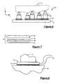
- FIG. 6 is a schematic illustration of the reconfigurable pallet having the modular stanchions secured using bonding packs
- FIG. 7 is a schematic illustration of a bonding pack
- FIG. 8 is a schematic illustration of a de-bonding process of the bonding packs.
- the assembly line 10 is illustrative of numerous types of assembly lines used across various industries.
- the generic assembly line 10 can depict an engine, a chassis, a vehicle sub-assembly or any type of vehicle oriented assembly line. More broadly, the generic assembly line 10 can depict any type of assembly line across all industries.
- a base structure 12 (shown in phantom) of a “to be assembled” product is moved through the assembly line 10 on a reconfigurable pallet 14 .
- the generic assembly line 10 includes multiple operation stages 16 . Single or multiple operations are performed on the product at each operation stage 16 . Such operations include, but are not limited to assembling a component, welding, treating the base structure (e.g., heat treatment), applying sealant, adhesive or the like and packaging the assembled product for shipping.
- Other inputs 18 are also included such as a component input, a sub-assembly input or a material input.
- a transfer 20 is also provided to transfer the reconfigurable pallets 14 to other parts of the assembly line 10 . It is appreciated that the assembly line 10 is merely exemplary in nature and can vary in configuration, the number of operation stages 16 , the number and location of component, sub-assembly or material inputs 18 , transfers 20 and the like.
- the reconfigurable pallet 14 includes a base 22 that supports multiple modular stanchions 24 .
- the base material corresponds to the loads it is designed to carry.
- the base 22 can be made of a strong metal material to support heavier products such as an engine. Other materials can be used to construct the base 22 .
- the material is selected based on the type of load that it is required to support.
- the multiple modular stanchions 24 support the base structure 12 (shown in phantom) of a product as it is transferred through the various operation stages 16 of the assembly line 10 .
- the product is representative of a generic product and can be any product that is assembled or treated along an assembly line.
- the modular stanchions 24 can be attached to or otherwise support the product.
- the modular stanchions 24 are adjustable to support various product types.
- the modular stanchions 24 can be positioned along x and y axes (see FIGS. 3 and 5 ) and also along a z axis (see FIGS. 2 and 4 ) transverse to the x and y axes.
- the modular stanchions 24 can be arranged in a first configuration to support one engine type for assembly in the assembly line 10 .
- the modular stanchions 24 can be reconfigured in a second configuration to accommodate a second engine type or another product altogether. In this manner, a single pallet 14 is reusable across assembly lines 10 and across products types.
- the modular stanchion 24 includes a stanchion base 26 , a stanchion 27 , a hydraulic fluid pump 28 and a support cylinder 30 .
- the stanchion base 26 rests on the pallet base 22 and is selectively positionable along the x and y axes.
- the fluid pump 28 is supported on the stanchion base 26 and is in fluid communication with the support cylinder 30 .
- the support cylinder 30 includes a rod 32 that has a support element 34 attached thereto. The rod 32 is laterally adjustable by varying the fluid pressure within the support cylinder 30 .
- the fluid pump 28 can be one of several types of fluid pumps known in the art including, but not limited to, a hydraulic screw-pump.
- a traditional hydraulic screw pump includes a hollow metal cylinder having a small opening at a closed end and a leak-free plunger screw-actuated at an open end. The small opening is connected to a hydraulic device such as a the support cylinder 30 .
- a hydraulic device such as a the support cylinder 30 .
- the plunger-screw When the plunger-screw is rotated clockwise, it moves axially inward, pressurizing the hydraulic fluid to actuate the hydraulic device.
- the plunger-screw When the plunger-screw is rotated counterclockwise, it moves axially outward and thus decreases the fluid pressure and deactivates the hydraulic device. It is anticipated that the reservoir of oil inside the screw-pump can serve several hydraulic devices.
- Actuation of the support cylinder 30 using the fluid pump 28 results in adjustment of the rod 32 .
- Adjustment of the rod 32 enables positioning of the support element 34 along the z axis.
- a gauge block or spacer (not shown) having an appropriate thickness can be implemented to raise the support cylinder 30 .
- another support cylinder 30 having a longer stroke can be used.
- the support elements 34 can vary in size and style between the modular stanchions 24 .
- the support elements 34 include, but are not limited to, buttons, round locators, diamond locators and pads.
- the support elements 34 can be interchanged on the rods 32 of the support cylinders 30 and can be fixedly attached to the base structure 12 to secure the base structure 12 to the reconfigurable pallet 14 . Additionally, such as in the case of a pad, the base structure 12 can rest on the support elements 34 , held in place by gravity. It is also anticipated that the support elements 34 can be articulated in various directions to accommodate the contours of the base structure 12 .
- the exemplary modular stanchion 24 includes hydraulic adjustment of the support element 34 along the z axis, it is anticipated that other mechanisms can be incorporated to achieve lateral adjustment of the support element 34 .
- a mechanical mechanism such as a rack and pinion system driven by an electric motor can be employed to position the support element 34 along the z axis.
- an adjustable tube that is slidable along the z axis and lockable in position by a pin can be implemented.
- fixed height modular stanchions can be implemented.
- the fixed height stanchions are similarly constructed to the adjustable height modular stanchion 24 described above and include a stanchion base, a stanchion, a support column and the support element.
- the support elements can be interchanged, the height of the support column is fixed. This height can vary from stanchion to stanchion.
- the z-axis coordinates for the various support elements can be predefined.
- the fixed height stanchions having the required z-axis height can be selected from a pool of fixed height stanchions and can be mounted to the pallet base to support the product.
- the modular stanchions 24 are selectively attached to the pallet base 22 using an adhesive.
- the adhesive provides an interfacial joint between the stanchion base 26 and the pallet base 22 .
- the adhesive preferably includes technical characteristics that enable simplicity and quick-configuration time. These technical characteristics include adequate bonding strength (e.g., >2000 psi), fast bonding time (e.g., ⁇ 15 seconds), simple bonding process, fast de-bonding time (e.g., ⁇ 15 seconds) and a simple de-bonding process. It is appreciated that the bonding strength and bonding/de-bonding times will vary based on application requirements and that the values provided herein are merely exemplary in nature.
- a prefabricated pre-form 40 is mounted to the pallet base 22 to define the x-y coordinates for each of the modular stanchions 24 . More particularly, the pre-form 40 functions as a template having a plurality of openings 42 that define a pattern. The pre-form 40 also includes locating pins 44 that interface with locating holes 46 on the pallet base 22 to center the pre-form 40 on the pallet base 22 .
- the pre-form 40 is set atop the pallet base 22 with the locator pins 44 and holes 46 centering the pre-form 40 on the pallet base 22 .
- An adhesive layer is applied to either the bottom of the stanchion base 26 or onto the top surface of the pallet base 22 in a space defined by the opening 42 .
- the modular stanchion 24 is set atop the pallet base through the desired opening 42 and the adhesive layer cures, securing the modular stanchion 24 to the pallet base 22 .
- the pre-form 40 is lifted off and the pallet 14 is ready to be used. After use, the modular stanchions 24 are de-bonded from the pallet base 22 and the surface of the pallet base 22 is cleaned and prepared to receive an alternative modular stanchion configuration.
- An alternative process for attaching the modular stanchion 24 to the pallet base can include a modified computer numerically controlled (CNC) x-y table or a robotic arm.
- the CNC table or robotic arm position the modular stanchions 24 at the appropriate x-y coordinates.
- the stanchion bases 26 are secured in position as described herein.
- An operator adjust the z-coordinate of each modular stanchion 24 in the case of an adjustable height modular stanchion 24 . Adjustment of the z-coordinate can be achieved hydraulically or manually, as described above.
- the operator re-checks the x, y and z coordinates of each modular stanchion 24 then releases the reconfigurable pallet 14 for use in the assembly line 10 .
- FIGS. 6 through 8 an alternative process for attaching a modular stanchion 24 to the pallet base 22 will be described in detail.
- the process described with respect to FIG. 5 is the preferred process when using an adhesive that includes all of the technical characteristics except for quick de-bonding time, which is the case for most commercially available adhesives.
- Other adhesives have been identified that include all of the technical characteristics except for quick bonding time.
- One such adhesive includes ElectReleaseTM E4 manufactured by EIC Laboratories. E4 requires a curing time of approximately 24 hours with 1 hour at 80° C. E4, however, has a quick de-bonding time (approximately 15 seconds) by applying a low DC voltage (e.g., 50V) across the bonded components.
- a low DC voltage e.g. 50V
- each of the modular stanchions 24 is bonded to the pallet base 22 by a bonding pack 50 .
- the bonding pack 50 includes a shim 52 bonded to the bottom of the stanchion base 26 via a quick de-bonding adhesive layer 54 .
- the bonding pack 50 is bonded to the pallet base 22 via a quick-bonding adhesive layer 56 .
- Many bonding packs 50 can be made prior to assembling the pallets 14 . In this manner, assembly time is not delayed by the time required for the quick de-bonding adhesive.
- the pre-form 40 is aligned on the pallet base 22 as described above.
- the quick bonding adhesive layer 56 is applied to either the stanchion base 26 or the pallet base 22 in the area defined by the opening 42 .
- the quick bonding adhesive layer 56 cures to secure the bonding pack 50 to the pallet base 22 .
- the pre-form 40 is removed from the pallet base 22 and the remaining components of the modular stanchions 24 are secured to their respective stanchion bases 26 .
- the stanchion base 26 and shim 52 are preferably formed of an electrically conductive material.
- the voltage de-bonds the modular stanchion 24 from the shim 52 and the modular stanchion 24 is removed from the pallet base 22 .
- Each of the modular stanchions 24 are removed from the pallet base 22 leaving the shims 52 bonded to the pallet base 22 by the quick bonding adhesive layer 56 .
- the shims 52 and quick bonding adhesive layer 56 are machined from the surface of the pallet base 22 and the pallet base is cleaned and prepared for an alternative modular stanchion configuration.
- the alternative process described above combines the advantages of commercially available quick bonding adhesives and quick de-bonding adhesives.
- the quick bonding adhesives enable rapid attachment of the modular stanchions 24 to the pallet base 22 using the prefabricated bonding packs 50 .
- the quick de-bonding adhesives enable rapid detachment of the modular stanchions 24 from the pallet base 22 . This enables immediate use of the modular stanchions 24 on another pallet base 22 , while the pallet base 22 is machined and cleaned.
- the reconfigurable pallet 14 Prior to use in the assembly line 10 , the reconfigurable pallet 14 is configured to support the specific base structure 12 and product to be assembled. More specifically, the x, y and z positions of each modular stanchion 24 are adjusted and the support element 34 geometries are configured for the specific support requirements of the base structure 12 .
- a dedicated set-up station (not shown) includes the bonding packs 50 , in the case of a quick de-bonding adhesive, and the pre-forms 40 to position the modular stanchions 24 at the appropriate x-y coordinates. The stanchion bases 26 are secured in position as described above.
- each modular stanchion 24 adjusts the z-coordinate of each modular stanchion 24 , in the case of adjustable height modular stanchions, or secures appropriate fixed height modular stanchions to the pallet base 22 .
- the operator re-checks the x, y and z coordinates of each modular stanchion 24 then releases the reconfigurable pallet 14 for use in the assembly line 10 .
- the reconfigurable pallet 14 of the present invention enables multiple spatial positioning for locating pins or support pads.
- the reconfigurable pallet 14 is adjustable to accommodate various product types. In this manner, significant savings is obtained by reducing design, engineering, manufacturing and purchasing of pallets for each product type. Further savings are achieved in the form of reduced capital investment and lead-time during transition between products.
Abstract
Description
Claims (9)
Priority Applications (1)
| Application Number | Priority Date | Filing Date | Title |
|---|---|---|---|
| US10/721,598 US7484464B2 (en) | 2003-11-25 | 2003-11-25 | Adhesive-based reconfigurable pallet system for assembly lines |
Applications Claiming Priority (1)
| Application Number | Priority Date | Filing Date | Title |
|---|---|---|---|
| US10/721,598 US7484464B2 (en) | 2003-11-25 | 2003-11-25 | Adhesive-based reconfigurable pallet system for assembly lines |
Publications (2)
| Publication Number | Publication Date |
|---|---|
| US20050109249A1 US20050109249A1 (en) | 2005-05-26 |
| US7484464B2 true US7484464B2 (en) | 2009-02-03 |
Family
ID=34591832
Family Applications (1)
| Application Number | Title | Priority Date | Filing Date |
|---|---|---|---|
| US10/721,598 Expired - Fee Related US7484464B2 (en) | 2003-11-25 | 2003-11-25 | Adhesive-based reconfigurable pallet system for assembly lines |
Country Status (1)
| Country | Link |
|---|---|
| US (1) | US7484464B2 (en) |
Cited By (10)
| Publication number | Priority date | Publication date | Assignee | Title |
|---|---|---|---|---|
| US20080202888A1 (en) * | 2007-02-28 | 2008-08-28 | Ka-Ming Lai | Controllable surface system |
| US20090235846A1 (en) * | 2008-03-19 | 2009-09-24 | Gm Global Technology Operations, Inc. | Reconfigurable pallet |
| US20110302784A1 (en) * | 2009-02-27 | 2011-12-15 | Shigemi Yamane | Aircraft structure manufacturing apparatus |
| CN103100899A (en) * | 2012-11-15 | 2013-05-15 | 无锡市航鹄科技有限公司 | High-precision milling groove punching positioning tool |
| CN105269362A (en) * | 2015-11-28 | 2016-01-27 | 孙新梅 | Drilling tool for heating drilling type V-shaped part |
| WO2016014482A1 (en) * | 2014-07-22 | 2016-01-28 | Blue Photon Technology & Workholding Systems L.L.C. | Method and devices to minimize work-piece distortion due to adhering stresses and changes in internal stresses |
| CN105290811A (en) * | 2015-10-31 | 2016-02-03 | 安新生 | W-type workpiece tapping tool based on safe control |
| US9821424B2 (en) | 2014-10-03 | 2017-11-21 | GM Global Technology Operations LLC | Manufacturing fixture |
| CN109530802A (en) * | 2018-12-21 | 2019-03-29 | 威斯卡特工业(中国)有限公司 | A kind of hydraulic cutting groove jig, numerical control band sawing machine and its technics of slot |
| US20200108478A1 (en) * | 2018-10-05 | 2020-04-09 | Compagnie Plastic Omnium | Vehicle Body Part Rack With Lateral Supports Able To Rotate The Vehicle Body Part |
Families Citing this family (15)
| Publication number | Priority date | Publication date | Assignee | Title |
|---|---|---|---|---|
| US20070023884A1 (en) * | 2005-08-01 | 2007-02-01 | Stora Enso Ab | Package |
| DE602006017080D1 (en) * | 2005-08-01 | 2010-11-04 | Stora Enso Ab | A PACKAGING |
| US20070182025A1 (en) * | 2006-02-07 | 2007-08-09 | Stora Enso Ab | Laminate structure and method of producing the same |
| DE202007009014U1 (en) | 2007-06-26 | 2008-11-13 | Kuka Systems Gmbh | Transportable component carrier |
| DE102009013726A1 (en) * | 2009-03-20 | 2010-09-30 | Mtu Aero Engines Gmbh | Device for fixing workpieces to a workpiece carrier and method for processing workpieces |
| CN102528500B (en) * | 2012-02-10 | 2013-11-20 | 中联重科股份有限公司 | Turntable fixture and machine tool with same |
| FR3005027B1 (en) * | 2013-04-30 | 2015-04-17 | Peugeot Citroen Automobiles Sa | DEVICE FOR THE FIXING INTO GEOMETRY OF TWO DIFFERENT CASES OF A MOTOR VEHICLE |
| CN104959862A (en) * | 2015-08-04 | 2015-10-07 | 安徽机电职业技术学院 | Clamping fixture for axis parts of different sizes |
| CN105269363A (en) * | 2015-11-28 | 2016-01-27 | 孙新梅 | Heating drilling tool for V-shaped workpiece |
| CN105312928A (en) * | 2015-11-28 | 2016-02-10 | 孙新梅 | Drilling technological equipment with annular water spray cooling function |
| US10449612B2 (en) | 2016-10-24 | 2019-10-22 | Steel 21, LLC | Methods of milling a piece of raw steel stock into a machine-ready piece of steel |
| KR101864703B1 (en) * | 2016-11-29 | 2018-06-05 | 동명대학교산학협력단 | Transfer pallet for component |
| CN106945912B (en) * | 2017-03-10 | 2018-12-04 | 共享智能装备有限公司 | A kind of production method of generally applicable sand core pallet |
| CN109773690A (en) * | 2019-02-26 | 2019-05-21 | 苏州超徕精工科技有限公司 | A kind of fixation device for workpiece bonding |
| CN110550298A (en) * | 2019-10-08 | 2019-12-10 | 黄萍 | Improved logistics tray |
Citations (19)
| Publication number | Priority date | Publication date | Assignee | Title |
|---|---|---|---|---|
| JPS57184028A (en) * | 1981-05-07 | 1982-11-12 | Matsushita Electric Ind Co Ltd | Pallet |
| US4848005A (en) * | 1987-02-03 | 1989-07-18 | D.E.A. Digital Electronic Automation S.P.A. | Rearrangeable supporting and positioning fixture, particularly for parts measurable on a gauging machine |
| US5110239A (en) * | 1991-04-26 | 1992-05-05 | The Boeing Company | Vacuum clamping system |
| US5153505A (en) * | 1991-11-05 | 1992-10-06 | The Johns Hopkins University | Adaptable multiport test fixture system |
| US5243745A (en) * | 1990-03-02 | 1993-09-14 | Proprietary Main, Inc. | Positioning fixture |
| US5364083A (en) * | 1992-07-15 | 1994-11-15 | The Boeing Company | Universal holding fixture end effector |
| US5562276A (en) * | 1994-09-14 | 1996-10-08 | Blick; John | Locator and hold down system for a machine |
| US5722646A (en) * | 1995-08-29 | 1998-03-03 | Cna Manufacturing Systems, Inc. | Flexible tooling apparatus |
| US5829151A (en) * | 1996-12-20 | 1998-11-03 | The Boeing Company | Multi-axis part positioning system |
| US5837901A (en) * | 1996-03-05 | 1998-11-17 | Dea-Brown & Sharpe S.P.A. | Reconfigurable supporting fixture, particularly for a measuring machine, and relative configuration method |
| US5984293A (en) * | 1997-06-25 | 1999-11-16 | Mcms, Inc. | Apparatus for holding printed circuit board assemblies in manufacturing processes |
| US5987765A (en) * | 1996-07-16 | 1999-11-23 | Brown & Sharpe Dea S.P.A. | Reconfigurable supporting element, particularly for measured parts on a measuring machine |
| US6158727A (en) * | 1998-04-28 | 2000-12-12 | Imi Norgren Limited | Supporting apparatus |
| US6408767B1 (en) * | 2000-03-01 | 2002-06-25 | Nikon Corporation | Low stiffness suspension for a stage |
| US6418602B2 (en) * | 1998-03-12 | 2002-07-16 | General Electro Mechanical Corporation | Flexible fixture system and method |
| JP2003076290A (en) * | 2001-09-06 | 2003-03-14 | Matsushita Electric Ind Co Ltd | Assembling device for display panel |
| US6644637B1 (en) | 2002-09-13 | 2003-11-11 | General Motors Corporation | Reconfigurable workholding fixture |
| US6702272B2 (en) * | 2000-11-02 | 2004-03-09 | Airline Hydraulics Corp. | Compliant locking support fixture |
| US7076856B2 (en) * | 2002-11-14 | 2006-07-18 | The Boeing Company | Adjustable system and method for supporting and joining structural members |
-
2003
- 2003-11-25 US US10/721,598 patent/US7484464B2/en not_active Expired - Fee Related
Patent Citations (19)
| Publication number | Priority date | Publication date | Assignee | Title |
|---|---|---|---|---|
| JPS57184028A (en) * | 1981-05-07 | 1982-11-12 | Matsushita Electric Ind Co Ltd | Pallet |
| US4848005A (en) * | 1987-02-03 | 1989-07-18 | D.E.A. Digital Electronic Automation S.P.A. | Rearrangeable supporting and positioning fixture, particularly for parts measurable on a gauging machine |
| US5243745A (en) * | 1990-03-02 | 1993-09-14 | Proprietary Main, Inc. | Positioning fixture |
| US5110239A (en) * | 1991-04-26 | 1992-05-05 | The Boeing Company | Vacuum clamping system |
| US5153505A (en) * | 1991-11-05 | 1992-10-06 | The Johns Hopkins University | Adaptable multiport test fixture system |
| US5364083A (en) * | 1992-07-15 | 1994-11-15 | The Boeing Company | Universal holding fixture end effector |
| US5562276A (en) * | 1994-09-14 | 1996-10-08 | Blick; John | Locator and hold down system for a machine |
| US5722646A (en) * | 1995-08-29 | 1998-03-03 | Cna Manufacturing Systems, Inc. | Flexible tooling apparatus |
| US5837901A (en) * | 1996-03-05 | 1998-11-17 | Dea-Brown & Sharpe S.P.A. | Reconfigurable supporting fixture, particularly for a measuring machine, and relative configuration method |
| US5987765A (en) * | 1996-07-16 | 1999-11-23 | Brown & Sharpe Dea S.P.A. | Reconfigurable supporting element, particularly for measured parts on a measuring machine |
| US5829151A (en) * | 1996-12-20 | 1998-11-03 | The Boeing Company | Multi-axis part positioning system |
| US5984293A (en) * | 1997-06-25 | 1999-11-16 | Mcms, Inc. | Apparatus for holding printed circuit board assemblies in manufacturing processes |
| US6418602B2 (en) * | 1998-03-12 | 2002-07-16 | General Electro Mechanical Corporation | Flexible fixture system and method |
| US6158727A (en) * | 1998-04-28 | 2000-12-12 | Imi Norgren Limited | Supporting apparatus |
| US6408767B1 (en) * | 2000-03-01 | 2002-06-25 | Nikon Corporation | Low stiffness suspension for a stage |
| US6702272B2 (en) * | 2000-11-02 | 2004-03-09 | Airline Hydraulics Corp. | Compliant locking support fixture |
| JP2003076290A (en) * | 2001-09-06 | 2003-03-14 | Matsushita Electric Ind Co Ltd | Assembling device for display panel |
| US6644637B1 (en) | 2002-09-13 | 2003-11-11 | General Motors Corporation | Reconfigurable workholding fixture |
| US7076856B2 (en) * | 2002-11-14 | 2006-07-18 | The Boeing Company | Adjustable system and method for supporting and joining structural members |
Cited By (14)
| Publication number | Priority date | Publication date | Assignee | Title |
|---|---|---|---|---|
| US20080202888A1 (en) * | 2007-02-28 | 2008-08-28 | Ka-Ming Lai | Controllable surface system |
| US20090235846A1 (en) * | 2008-03-19 | 2009-09-24 | Gm Global Technology Operations, Inc. | Reconfigurable pallet |
| US8092127B2 (en) * | 2008-03-19 | 2012-01-10 | GM Global Technology Operations LLC | Reconfigurable pallet |
| US20110302784A1 (en) * | 2009-02-27 | 2011-12-15 | Shigemi Yamane | Aircraft structure manufacturing apparatus |
| US8869367B2 (en) * | 2009-02-27 | 2014-10-28 | Mitsubishi Heavy Industries, Ltd. | Aircraft structure manufacturing apparatus |
| CN103100899A (en) * | 2012-11-15 | 2013-05-15 | 无锡市航鹄科技有限公司 | High-precision milling groove punching positioning tool |
| US10336003B2 (en) | 2014-07-22 | 2019-07-02 | Blue Photon Technology & Workholding Systems LLC | Method and devices to minimize work-piece distortion due to adhering stresses and changes in internal stresses |
| WO2016014482A1 (en) * | 2014-07-22 | 2016-01-28 | Blue Photon Technology & Workholding Systems L.L.C. | Method and devices to minimize work-piece distortion due to adhering stresses and changes in internal stresses |
| US9821424B2 (en) | 2014-10-03 | 2017-11-21 | GM Global Technology Operations LLC | Manufacturing fixture |
| CN105290811A (en) * | 2015-10-31 | 2016-02-03 | 安新生 | W-type workpiece tapping tool based on safe control |
| CN105269362A (en) * | 2015-11-28 | 2016-01-27 | 孙新梅 | Drilling tool for heating drilling type V-shaped part |
| US20200108478A1 (en) * | 2018-10-05 | 2020-04-09 | Compagnie Plastic Omnium | Vehicle Body Part Rack With Lateral Supports Able To Rotate The Vehicle Body Part |
| US10953503B2 (en) * | 2018-10-05 | 2021-03-23 | Compagnie Plastic Omnium | Vehicle body part rack with lateral supports able to rotate the vehicle body part |
| CN109530802A (en) * | 2018-12-21 | 2019-03-29 | 威斯卡特工业(中国)有限公司 | A kind of hydraulic cutting groove jig, numerical control band sawing machine and its technics of slot |
Also Published As
| Publication number | Publication date |
|---|---|
| US20050109249A1 (en) | 2005-05-26 |
Similar Documents
| Publication | Publication Date | Title |
|---|---|---|
| US7484464B2 (en) | Adhesive-based reconfigurable pallet system for assembly lines | |
| US7055679B2 (en) | Reconfigurable magnetic fixturing pallets for an assembly line | |
| AT517254B1 (en) | Method of handling aligned pairs of wafers | |
| CN111098507B (en) | Method for in-situ gluing assembly of satellite composite material truss | |
| US20130341848A1 (en) | Assembly fixture for a workpiece | |
| WO2014156745A1 (en) | Method for bonding fuselage and strong back | |
| CN105855778A (en) | Flexible positioning mechanism for car body welding production line | |
| DE102012221637A1 (en) | Workpiece placement apparatus and method thereto | |
| US20050110204A1 (en) | Reconfigurable mechanical fixturing pallets for assembly lines | |
| CN106736217A (en) | A kind of plates of automobile welds six axis robot turning operation platform | |
| JP2002001626A (en) | Automatic jig changing method in welding line | |
| CN207139167U (en) | A kind of loading assembly | |
| JPH06220883A (en) | Manufacture of lift arm assembly | |
| Jonsson et al. | Coordinate controlled fixturing for affordable reconfigurable tooling | |
| CN216882474U (en) | Positioning mechanism for nut welding | |
| CN109894786B (en) | Instrument board skeleton welding frock | |
| CN209773996U (en) | Fixing jig utilizing inner hole for positioning | |
| CN215699757U (en) | Material pressing tool | |
| CN220653632U (en) | Printing jig for reflow soldering of semiconductor element | |
| CN219805738U (en) | Clamp for processing core special-shaped piece of control unit of new energy automobile | |
| EP1375058A3 (en) | Clamping device for a pallet device | |
| CN209665185U (en) | A kind of plate workpiece processing clamping device | |
| CN111300331B (en) | Large-pressure flip bonding method for bonding chip substrate after pre-welding | |
| CN104439421A (en) | Drilling equipment for drilling lower bracket for reaction rod in dumper bodies | |
| JP6486340B2 (en) | Pressure bonding apparatus and pressure bonding method |
Legal Events
| Date | Code | Title | Description |
|---|---|---|---|
| AS | Assignment |
Owner name: GENERAL MOTORS CORPORATION, MICHIGAN Free format text: ASSIGNMENT OF ASSIGNORS INTEREST;ASSIGNORS:SHEN, CHI-HUNG;LIN, YHU-TIN;REEL/FRAME:014746/0488;SIGNING DATES FROM 20031110 TO 20031119 |
|
| AS | Assignment |
Owner name: GM GLOBAL TECHNOLOGY OPERATIONS, INC., MICHIGAN Free format text: ASSIGNMENT OF ASSIGNORS INTEREST;ASSIGNOR:GENERAL MOTORS CORPORATION;REEL/FRAME:022102/0533 Effective date: 20050119 Owner name: GM GLOBAL TECHNOLOGY OPERATIONS, INC.,MICHIGAN Free format text: ASSIGNMENT OF ASSIGNORS INTEREST;ASSIGNOR:GENERAL MOTORS CORPORATION;REEL/FRAME:022102/0533 Effective date: 20050119 |
|
| STCF | Information on status: patent grant |
Free format text: PATENTED CASE |
|
| AS | Assignment |
Owner name: UNITED STATES DEPARTMENT OF THE TREASURY, DISTRICT Free format text: SECURITY AGREEMENT;ASSIGNOR:GM GLOBAL TECHNOLOGY OPERATIONS, INC.;REEL/FRAME:022201/0547 Effective date: 20081231 Owner name: UNITED STATES DEPARTMENT OF THE TREASURY,DISTRICT Free format text: SECURITY AGREEMENT;ASSIGNOR:GM GLOBAL TECHNOLOGY OPERATIONS, INC.;REEL/FRAME:022201/0547 Effective date: 20081231 |
|
| AS | Assignment |
Owner name: CITICORP USA, INC. AS AGENT FOR BANK PRIORITY SECU Free format text: SECURITY AGREEMENT;ASSIGNOR:GM GLOBAL TECHNOLOGY OPERATIONS, INC.;REEL/FRAME:022553/0399 Effective date: 20090409 Owner name: CITICORP USA, INC. AS AGENT FOR HEDGE PRIORITY SEC Free format text: SECURITY AGREEMENT;ASSIGNOR:GM GLOBAL TECHNOLOGY OPERATIONS, INC.;REEL/FRAME:022553/0399 Effective date: 20090409 |
|
| AS | Assignment |
Owner name: GM GLOBAL TECHNOLOGY OPERATIONS, INC., MICHIGAN Free format text: RELEASE BY SECURED PARTY;ASSIGNOR:UNITED STATES DEPARTMENT OF THE TREASURY;REEL/FRAME:023124/0470 Effective date: 20090709 Owner name: GM GLOBAL TECHNOLOGY OPERATIONS, INC.,MICHIGAN Free format text: RELEASE BY SECURED PARTY;ASSIGNOR:UNITED STATES DEPARTMENT OF THE TREASURY;REEL/FRAME:023124/0470 Effective date: 20090709 |
|
| AS | Assignment |
Owner name: GM GLOBAL TECHNOLOGY OPERATIONS, INC., MICHIGAN Free format text: RELEASE BY SECURED PARTY;ASSIGNORS:CITICORP USA, INC. AS AGENT FOR BANK PRIORITY SECURED PARTIES;CITICORP USA, INC. AS AGENT FOR HEDGE PRIORITY SECURED PARTIES;REEL/FRAME:023127/0273 Effective date: 20090814 Owner name: GM GLOBAL TECHNOLOGY OPERATIONS, INC.,MICHIGAN Free format text: RELEASE BY SECURED PARTY;ASSIGNORS:CITICORP USA, INC. AS AGENT FOR BANK PRIORITY SECURED PARTIES;CITICORP USA, INC. AS AGENT FOR HEDGE PRIORITY SECURED PARTIES;REEL/FRAME:023127/0273 Effective date: 20090814 |
|
| AS | Assignment |
Owner name: UNITED STATES DEPARTMENT OF THE TREASURY, DISTRICT Free format text: SECURITY AGREEMENT;ASSIGNOR:GM GLOBAL TECHNOLOGY OPERATIONS, INC.;REEL/FRAME:023156/0001 Effective date: 20090710 Owner name: UNITED STATES DEPARTMENT OF THE TREASURY,DISTRICT Free format text: SECURITY AGREEMENT;ASSIGNOR:GM GLOBAL TECHNOLOGY OPERATIONS, INC.;REEL/FRAME:023156/0001 Effective date: 20090710 |
|
| AS | Assignment |
Owner name: UAW RETIREE MEDICAL BENEFITS TRUST, MICHIGAN Free format text: SECURITY AGREEMENT;ASSIGNOR:GM GLOBAL TECHNOLOGY OPERATIONS, INC.;REEL/FRAME:023161/0911 Effective date: 20090710 Owner name: UAW RETIREE MEDICAL BENEFITS TRUST,MICHIGAN Free format text: SECURITY AGREEMENT;ASSIGNOR:GM GLOBAL TECHNOLOGY OPERATIONS, INC.;REEL/FRAME:023161/0911 Effective date: 20090710 |
|
| AS | Assignment |
Owner name: GM GLOBAL TECHNOLOGY OPERATIONS, INC., MICHIGAN Free format text: RELEASE BY SECURED PARTY;ASSIGNOR:UAW RETIREE MEDICAL BENEFITS TRUST;REEL/FRAME:025311/0725 Effective date: 20101026 Owner name: GM GLOBAL TECHNOLOGY OPERATIONS, INC., MICHIGAN Free format text: RELEASE BY SECURED PARTY;ASSIGNOR:UNITED STATES DEPARTMENT OF THE TREASURY;REEL/FRAME:025245/0347 Effective date: 20100420 |
|
| AS | Assignment |
Owner name: WILMINGTON TRUST COMPANY, DELAWARE Free format text: SECURITY AGREEMENT;ASSIGNOR:GM GLOBAL TECHNOLOGY OPERATIONS, INC.;REEL/FRAME:025327/0262 Effective date: 20101027 |
|
| AS | Assignment |
Owner name: GM GLOBAL TECHNOLOGY OPERATIONS LLC, MICHIGAN Free format text: CHANGE OF NAME;ASSIGNOR:GM GLOBAL TECHNOLOGY OPERATIONS, INC.;REEL/FRAME:025780/0902 Effective date: 20101202 |
|
| FPAY | Fee payment |
Year of fee payment: 4 |
|
| AS | Assignment |
Owner name: GM GLOBAL TECHNOLOGY OPERATIONS LLC, MICHIGAN Free format text: RELEASE BY SECURED PARTY;ASSIGNOR:WILMINGTON TRUST COMPANY;REEL/FRAME:034371/0676 Effective date: 20141017 |
|
| FPAY | Fee payment |
Year of fee payment: 8 |
|
| FEPP | Fee payment procedure |
Free format text: MAINTENANCE FEE REMINDER MAILED (ORIGINAL EVENT CODE: REM.); ENTITY STATUS OF PATENT OWNER: LARGE ENTITY |
|
| LAPS | Lapse for failure to pay maintenance fees |
Free format text: PATENT EXPIRED FOR FAILURE TO PAY MAINTENANCE FEES (ORIGINAL EVENT CODE: EXP.); ENTITY STATUS OF PATENT OWNER: LARGE ENTITY |
|
| STCH | Information on status: patent discontinuation |
Free format text: PATENT EXPIRED DUE TO NONPAYMENT OF MAINTENANCE FEES UNDER 37 CFR 1.362 |
|
| FP | Lapsed due to failure to pay maintenance fee |
Effective date: 20210203 |