US7491014B2 - System and method of the automatic compaction of soil - Google Patents
System and method of the automatic compaction of soil Download PDFInfo
- Publication number
- US7491014B2 US7491014B2 US10/553,569 US55356904A US7491014B2 US 7491014 B2 US7491014 B2 US 7491014B2 US 55356904 A US55356904 A US 55356904A US 7491014 B2 US7491014 B2 US 7491014B2
- Authority
- US
- United States
- Prior art keywords
- soil compacting
- soil
- travel
- compaction
- path
- Prior art date
- Legal status (The legal status is an assumption and is not a legal conclusion. Google has not performed a legal analysis and makes no representation as to the accuracy of the status listed.)
- Expired - Fee Related, expires
Links
Images


Classifications
-
- E—FIXED CONSTRUCTIONS
- E02—HYDRAULIC ENGINEERING; FOUNDATIONS; SOIL SHIFTING
- E02D—FOUNDATIONS; EXCAVATIONS; EMBANKMENTS; UNDERGROUND OR UNDERWATER STRUCTURES
- E02D3/00—Improving or preserving soil or rock, e.g. preserving permafrost soil
- E02D3/02—Improving by compacting
- E02D3/046—Improving by compacting by tamping or vibrating, e.g. with auxiliary watering of the soil
- E02D3/074—Vibrating apparatus operating with systems involving rotary unbalanced masses
-
- E—FIXED CONSTRUCTIONS
- E01—CONSTRUCTION OF ROADS, RAILWAYS, OR BRIDGES
- E01C—CONSTRUCTION OF, OR SURFACES FOR, ROADS, SPORTS GROUNDS, OR THE LIKE; MACHINES OR AUXILIARY TOOLS FOR CONSTRUCTION OR REPAIR
- E01C19/00—Machines, tools or auxiliary devices for preparing or distributing paving materials, for working the placed materials, or for forming, consolidating, or finishing the paving
- E01C19/004—Devices for guiding or controlling the machines along a predetermined path
- E01C19/006—Devices for guiding or controlling the machines along a predetermined path by laser or ultrasound
Definitions
- the present invention relates to a system and a method for automated soil compacting.
- a mobile soil compacting device whose direction of travel is stabilized is known.
- the device has a motion acquisition apparatus for detecting the actual travel movement of the soil compacting device.
- the actual travel movement is compared with a target value predetermined by the operator. Any deviations that may occur, due e.g. to disturbances, are automatically corrected by a travel regulation device.
- the soil compacting device e.g. a vibration plate or a roller, stably follows a travel path that is predetermined by the operator.
- a roller device made up of a plurality of roll tires that automatically travels a predetermined path, thus compacting the soil.
- the predetermination of the compacting path takes place either using mechanical devices, e.g. markings on the soil that is to be compacted, or through GPS data that were previously acquired during the application of the asphalt to be compacted.
- the goal of the described solution is to cause the roller device to travel as precisely as possible along the side edge of the asphalt in order to achieve a uniform compacting.
- the underlying object of the present invention is to indicate a soil compacting system and an associated method with which the operability and operator comfort, as well as the economical affordability, of a soil compacting device can be further improved.
- the soil compacting system is equipped with a mobile and steerable soil compacting device, e.g. a vibration plate or a roller, and a control device, the control device having a surface definition device, a position detection device, and a motion controller.
- the surface definition device is used by the operator to define a surface to be compacted, as well as the associated boundaries of the surface. It is thus possible for the operator to input indications concerning the surface to be compacted into the soil compacting system, or to communicate the surface boundaries to the system in some other way.
- the position detection device is used to detect the current position of the soil compacting device; it must at least be possible to detect the position of the soil compacting device in the vicinity of the surface boundaries, i.e., when a close approach is made to the boundaries of the surface.
- the motion controller can be used to change the direction of travel of the soil compacting device.
- a target value for a travel movement is given to the soil compacting device by the motion controller in such a way that the soil compacting device does not cross the respective surface boundary, but rather continues its travel within the surface. If in this way the soil compacting device approaches one of the boundaries of the surface, and there is a danger that given unchanged travel the soil compacting device would cross the surface boundary, the motion controller can, by changing the direction of travel, introduce the appropriate measures to prevent the surface boundary from being crossed.
- the motion controller can be subject to various rules that are further explained below.
- the position detection device is fashioned at least for the detection of an approach of the soil compacting device to one of the surface boundaries, the direction of travel being capable of being changed by the motion controller if the position detection device determines that the surface boundary is being approached.
- the position detection device Due to the fact that the position detection device only has to determine when the soil compacting device is approaching a surface boundary, but does not however permanently detect the actual position of the soil compacting device within the overall surface, the position detection device can be constructed comparatively simply, and thus inexpensively.
- the position detection device need emit a signal only when the soil compacting device approaches the respective surface boundary, e.g., when a predetermined distance value of one meter is undershot.
- This signal is received by the motion controller, which thereupon introduces measures for changing the direction of travel in order to prevent crossing of the surface boundary.
- the surface definition device can enable a definition of the surface boundaries with the aid of mechanical, optical, magnetic, inductive, or capacitive means. Particularly simple is for example an identification of the surface boundaries using a stretched wire over which the soil compacting device may not travel.
- An antenna acting as a position detection device, or a suitable sensor, can determine when the soil compacting device is approaching the wire, and can transmit the required approach signal to the motion controller.
- the surface boundaries can for example also be defined by spray-painted colored markings or by laser beams, in which case the position detection device has optical means (photodetectors, cameras, or the like) for the evaluation of the optical signals.
- optical means photodetectors, cameras, or the like
- the motion controller effects a change of the travel direction from the original travel direction with a predetermined angle that remains constant during the entire compacting process. This means that when a surface boundary is reached, the vibration plate turns to the left or to the right at the predetermined angle, and travel then continues in a straight line.
- the angle of change is an acute angle, less than 90°, so that the soil compacting device is “reflected” by the surface boundary at an acute angle.
- the turning angle it is possible for the turning angle to be different in each case, and to be selected randomly or from a predetermined table by the motion controller.
- a path planning device is provided in order to define a predetermined value for a travel path (course) based on the defined surface, the soil compacting device traveling over the surface to be compacted completely at least once while adhering to the predetermined travel path.
- a travel path can be planned that the soil compacting device must follow in order to travel over the surface to be compacted.
- the travel path planning can be carried out in automated fashion with computer support, also taking into account the width of the soil compacting device.
- the operator merely needs to indicate the travel path coordinates, e.g. by drawing the travel path on a surface displayed on a screen.
- the position detection device is fashioned for the constant detection of the current position of the soil compacting device within the surface boundaries. This means that the position detection device always knows the exact position, and possibly even the direction of travel, of the soil compacting device.
- the motion controller is fashioned such that it determines a target value for a travel movement of the soil compacting device on the basis of a comparison of the current position of the soil compacting device, communicated by the position detection device, with the predetermined travel path indicated by the path planning device. This target value is selected such that the soil compacting device follows the predetermined travel path.
- the motion controller ensures that the position of the soil compacting device does not deviate from the predetermined travel path. Rather, by influencing the drive mechanisms of the soil compacting device, in particular the advance and steering mechanisms, the motion controller can ensure that the soil compacting device follows the predetermined path.
- the surface definition device has a coordinate detection device for determining absolute geographical locus coordinates of its current location.
- a memory device with geographical locus information concerning the region of the surface to be compacted is coupled to the surface definition device.
- the surface definition device can prepare required locus information concerning the region in which the surface to be compacted is located, and to present this information to the operator if necessary.
- the surface definition device can determine its location with the aid of a GPS receiver, and can read out associated locus data from a magneto-optical storage medium (CD-ROM, DVD-ROM) and display this data to the operator on a display device. It is then easy for the operator to input, on the display screen, the necessary indications for the definition of the surface to be compacted.
- the surface boundaries can be defined by absolute locus coordinates.
- the definition of the surface boundaries in terms of absolute locus coordinates is also useful in particular if the position detection device also determines the absolute locus coordinates of the soil compacting device. The respective coordinates can then be suitably brought into accord with one another.
- the travel path predetermination can be defined by the path planning device in the form of absolute or relative geographical locus coordinates.
- Relative geographical locus coordinates have the advantage that, on the basis of a reference point, relative indications (angles, directions, compass points, travel distances) are sufficient to define the travel path.
- the path planning device has mathematical algorithms for path-optimized and/or time-optimized path planning. Due to the fact that certain tolerances will occur in any case during the travel of a soil compacting device, the demands on the optimization algorithms need not be set very high. Thus, for most cases it is sufficient if the algorithms plan a back-and-forth movement of the soil compacting device, or a meander-shaped or spiral-shaped travel path.
- the components of the control device in particular the surface definition device, the motion controller, or the path planning device, are situated so as to be spatially separate from the soil compacting device.
- the soil compacting device is exposed to strong vibrations. If the named components can be set up not on the soil compacting device itself, but rather spatially separate therefrom, more sensitive electronic components can be used that would quickly become damaged if they were used in the vicinity of a vibration exciter of the soil compacting device.
- a radio path, laser path, or infrared path can advantageously be used. This path should be used to communicate at least the target value from the motion controller.
- an input device is provided for the manual modification of the target value predetermined by the motion controller.
- an input device is provided for the manual modification of the target value predetermined by the motion controller.
- the position detection device is coupled to a memory device, possibly provided spatially separate from the soil compacting device, in order to store data concerning the positions reached by the soil compacting device.
- data can for example be absolute geographical locus coordinates.
- the stored data can for example be given to an evaluation device that, taking into account the data of the surface definition device, represents the achieved compacting, for example graphically.
- the predetermined surface boundaries can be shown on a display by the evaluation device, as can the surface already compacted by the soil compacting device at the respective point in time. This makes it very easy for the operator to determine whether the soil compacting device has traveled and compacted the predetermined surface in the desired manner.
- the graphic display can also take into account the width of the soil compacting device, and thus the width of the compacted track.
- the soil compacting system uses a soil compacting device as is known for example from DE 100 53 446 A1.
- a soil compacting device has a travel direction stabilization that makes it possible for the soil compacting device to follow exactly the path predetermined by an operator.
- the soil compacting device has a drive mechanism, comprising for example a vibration exciter, for producing an advance motion, a steering device for producing a yaw moment about a vertical axle of the soil compacting device, and a movement detection device for detecting an actual value of the travel movement.
- a travel regulation device is provided that can be provided with the actual value and the target value predetermined by the motion controller of the soil compacting system, and that controls the steering device, or the travel drive mechanism, in such a way that the difference between the actual value and the target value is minimized.
- the soil compacting device known from DE 100 53 446 A1 is thus further developed by the present invention. While in that device, the determination of the target value is carried out by the operator via remote control, according to the present invention the target value is predetermined by the motion controller, which attempts to move the soil compacting device within the area that is to be compacted.
- the travel direction stabilization known from DE 100 53 446 A1 makes the work of the motion controller easier, because disturbances during the soil compacting, due e.g. to uneven ground, stones, cross-forces, etc., are immediately regulated out by the soil compacting device itself, and do not cause the soil compacting device to deviate from the predetermined course.
- the soil compacting device has at least two control loops.
- the outer control loop comprises the motion controller, and ensures that the soil compacting device follows a particular path or course.
- the path can be a more or less randomly determined path within the boundaries of the surface to be compacted, or can be a travel path predetermined precisely by the path planning device.
- the inner control loop is coupled directly to the soil compacting device, and recognizes even slight deviations from a travel direction predetermined by the outer control loop, given rectilinear or curved travel of the soil compacting device. The combination of the two control loops makes it possible to move the soil compacting device on the surface to be compacted in a very precise manner.
- a vibration plate suitable for use as a soil compacting device is known, and is described in detail in DE 100 53 446 A1, so that repetition here is unnecessary.
- the soil compacting device has a vibration exciter having two shafts that are parallel to one another and that are positively connected so as to be capable of rotation in opposite directions, each shaft bearing an imbalance mass, and whose phase position to one another is adjustable. By adjusting the phase position, it is possible to effect a traveling movement of the vibration plate in the forward and backward directions.
- a plurality of vibration-exciting devices are provided in the vibration plate that operate according to the same two-shaft principle described above.
- the advance direction of at least one of the vibration-exciting devices differs from that of the other.
- the vibration-exciting devices not being used for advance or for steering can here be set such that they produce only a vertical oscillation, which can be used exclusively for soil compacting, as is also described in DE 100 53 446 A1.
- the soil contact plate charged by the vibration-exciting devices has an essentially circular outline. This outline makes it particularly easy to move the vibration plate uniformly in all compass directions.
- the soil compacting system according to the present invention can be used to realize two alternative methods for automated soil compacting:
- the soil compacting device is moved automatically within the surface boundaries, preferably in a straight line, and an approach of the soil compacting device to one of the surface boundaries is detected.
- an approach of the soil compacting device to one of the surface boundaries is detected.
- there takes place an automatic change of the direction of travel of the soil compacting device such that the soil compacting device does not cross the respective surface boundary, but rather continues its travel within the surface.
- the second method according to the present invention it is likewise possible first to define the surface boundaries of the surface to be compacted, the data representing the surface boundaries being capable of being stored. On the basis of these data, a specification for a travel path is planned with which it is ensured that the soil compacting device completely covers the surface to be compacted at least once while adhering to the predetermined travel path. Finally, the soil compacting device is automatically moved along the predetermined travel path.
- the previously described constructions of the present invention are essentially intended to achieve a geometrical predetermination or influencing of the travel path of the soil compacting device.
- a compaction result detection device 19 is provided for detecting the actual state of compaction of the compacted soil. See for example DE 100 46 336 A 1, WO-A-98-17865, and WO-A-95-10664, in which such possibilities for determining the state of compaction are discussed.
- the information obtained in this way about the actual state of compaction of the soil is compared with a target value that the operator can input via a suitable input medium, but for example also by remote control or via a computer (laptop). If it is recognized that the actual compaction state exceeds the target compaction state, and thus that the desired compaction has been achieved in this area of the soil, the path planning device can carry out a modification of the predetermined travel path in such a way that the relevant area of the soil is not traveled over again.
- the path planning device to define a strategy for predetermining a path-optimized or time-optimized travel path for the movement of the soil compacting device. This is helpful in particular when a plurality of passes of the soil compacting device over the soil is required.
- FIG. 1 shows a schematic top view of a surface to be compacted, for the explanation of a first specific embodiment of the present invention
- FIG. 2 shows a schematic representation of a soil compacting system according to the present invention, in the first specific embodiment
- FIG. 3 shows a schematic representation of a surface to be compacted, for the explanation of a second specific embodiment of the present invention
- FIG. 4 shows a diagram for the explanation of the travel regulation in the second specific embodiment of the present invention.
- FIG. 5 shows various variants of a soil compacting device for the soil compacting system according to the present invention.
- FIG. 1 shows, in a schematic top view, a surface 1 to be compacted that is enclosed or defined by surface boundaries 2 that are invisible in reality.
- Surface 1 is made up for example of loosely piled soil consisting of gravel or earth that is to be hardened through compacting by a soil compacting device 3 .
- a soil compacting device 3 a known vibration roller or a vibration plate is suitable in a standard manner.
- Soil compacting device 3 has at least one vibration exciter with which a roll tire drum (in the case of the roller) or a soil contact plate (in the case of the vibration plate) is charged with a preferably vertical oscillation.
- the soil compacting principle has long been known and has proved its usefulness, so that further explanation is not necessary.
- FIG. 1 shows that soil compacting device 3 has been moved along a travel path 4 within surface boundaries 2 , and in this way has already compacted a part of surface 1 .
- travel path 4 runs essentially in a spiral shape.
- remote control device 5 that communicates control commands to soil compacting device 3 via a cable or in wireless fashion via a radio, infrared, or laser path, thus monitoring the forward, backward, or steered movement of soil compacting device 3 .
- remote control device 5 is held by an operator who can use it to make the desired control commands.
- remote control device 5 has significantly more components and functions than is known from the prior art. This is illustrated in connection with FIG. 2 .
- remote control device 5 also called the control device
- the surface definition device 6 , path planning device 7 , and motion controller 8 a can be situated particularly advantageously as software in a computer 10 , e.g. a laptop, having an input device 11 and a display 12 .
- remote control device 5 is coupled to a receiver 14 on soil compacting device 3 via a radio, infrared, or laser path, said receiver forwarding the control signals received from remote control device 5 to a travel regulation device 15 .
- Travel regulation device 15 of soil compacting device 3 is used to control a vibration exciter 16 that introduces, in a known manner, a vertical oscillation into a soil contact plate 17 for the purpose of soil compacting.
- Vibration exciter 16 is made up of what is known as a two-shaft exciter, in which shafts 25 , 26 are coupled with one another in positive fashion so as to be capable of rotating in different directions, each shaft bearing at least one imbalance mass.
- vibration exciter 16 is also used to produce a force in the direction of travel (forward or backward), as well as to produce a yaw moment about the vertical axle of soil compacting device 3 in order to produce a steered movement.
- Such a vibration exciter 16 is known for example from DE 100 53 446 A1, as well as from DE-G 78 18 542.9, so that further explanation is not necessary.
- a position detection device 18 for detecting the current position of soil compacting device 3 is provided on soil compacting device 3 .
- Position detecting device 18 can for example be a GPS receiver.
- position detection device 18 is situated on soil compacting device 3 , it is sufficient for it to be fashioned for the determination of absolute geographical locus coordinates of its own location. If, however, position detection device 18 is set up externally to soil compacting device 3 , it must of course be able to determine the locus coordinates of the respective location of soil compacting device 3 .
- motion controller 8 a on soil compacting device 3 instead of in remote control device 5 (reference character 8 b ).
- remote control device 5 reference character 8 b
- all electronic devices should be situated as far as possible from soil compacting device 3 , in order to avoid damage to them due to the strong vibrations of vibration exciter 16 .
- the required data should be generated at remote control device 5 , and should then be communicated only for the controlling of vibration exciter 16 to soil compacting device 3 , via receiver 14 and travel regulation device 15 .
- a memory device (not shown), e.g. a CD-ROM, is provided on which geographical locus data are stored relating at least to the area in which surface 1 to be compacted is located.
- Such storage media are available e.g. for navigation systems in vehicles.
- surface definition device 6 receives the indications required to determine the geographical locus information from the locus memory device and to represent this information on display 12 .
- input device 11 which can include a known mouse control unit or some other graphic input means, the operator defines the boundaries 2 of surface 1 to be compacted on display 12 .
- the graphic inputs from the operator are converted into absolute or relative locus coordinates, and are made available to path planning device 7 .
- Absolute locus coordinates e.g. in the form of GPS coordinates, are particularly well-suited for a precise soil compacting of a larger surface.
- the position detection device can have for example a transmitter, situated in the vicinity of surface 1 to be compacted, that sends a particular signal out over surface 1 .
- a second transmitter is advantageously set up that is spatially separated from the first transmitter and that also radiates a signal, so that a receiver belonging to position detection device 18 on soil compacting device 3 can determine the precise relative position, and if necessary the relative motion, to the transmitters by evaluating the signals (e.g. by determining interferences or phase differences).
- the second transmitter can also be formed by a transponder to which a second signal is not externally supplied and that merely returns the signal of the first transmitter, so that the expensive laying of cables to the second transmitter is omitted.
- path planning device 7 determines a travel path on which vibration plate 3 must move in order to completely compact surface 1 .
- a target determination for the path planning a spiral-shaped path, a meandering or strip-shaped course, or a zigzag movement of the path.
- different movement schemata are possible that can be selected by the operator.
- the goal of the path planning is to travel completely over the surface 1 to be compacted at least once. In order to enable the achievement of a sufficient soil compacting, however, it is often required to travel over the surface several times. This requirement can also be taken into account in the path planning.
- Soil compacting device 3 is brought by the operator to the surface 1 to be compacted, or to the vicinity of this surface, manually, e.g. with the aid of input device 9 .
- motion controller 8 a in remote control device 5 obtains on the one hand the data representing the predetermined travel path 4 from path planning device 7 , and obtains on the other hand signals from position detection device 18 , which informs motion controller 8 a, 8 b concerning the current position of soil compacting device 3 .
- motion controller 8 a, 8 b then introduces the corresponding measures to move soil compacting device 3 on the course determined by path planning device 7 . If soil compacting device 3 deviates from the predetermined travel path 4 , motion controller 8 a / 8 b provides corresponding counter-regulation in order to compensate the deviation.
- Input device 9 is available to the operator for emergency cases or for particular obstacles; this input device 9 , in the manner of a classic remote control device, influences the travel behavior of soil compacting device 3 via receiver 14 and travel regulation device 15 .
- input device 9 it is also possible to use input device 9 to subsequently modify the target value predetermined by motion controller 8 a / 8 b, and only then to forward this target value to travel regulation device 15 in order to control vibration exciter 16 .
- input device 9 can at all times override the automatic controlling of soil compacting device 3 . In this way, the operator retains the ability to control soil compacting device 3 at all times, independent of the automatic mechanism.
- position detection device 18 can transmit its data to control device 5 , it is useful if on the one hand receiver 14 is also fashioned as a transmitter, and on the other hand transmitter 13 is also fashioned as a receiver. In this way, a constant exchange of data is possible between control device 5 and soil compacting device 3 , so that other information not relating to the present invention, such as e.g. motor speed, vibration frequencies, vibration amplitudes, oil temperature, data for determining the current state of compaction of the soil, etc., can be transmitted and displayed e.g. on display 12 .
- other information not relating to the present invention such as e.g. motor speed, vibration frequencies, vibration amplitudes, oil temperature, data for determining the current state of compaction of the soil, etc.
- control device/remote control device 5 The spatial arrangement of the components of the control device/remote control device 5 is not as strict as is shown in FIG. 2 . Thus, it is easily possible to situate at least some individual components of control device 5 directly on soil compacting device 3 , if this is useful. It is also possible to situate the complete control device 5 , i.e. including input device 11 and display 12 , directly on soil compacting device 3 . This can be useful in particular if the definition of the surface is to take place in a particularly simple manner, e.g. without the aid of GPS coordinates.
- the data of position detection device 18 are additionally stored in a memory device that is coupled to an evaluation device.
- the evaluation device is able to graphically display the data of position detection device 18 , e.g. on display 12 .
- the travel path 4 predetermined by path planning device 7 can be displayed on display 12 , which improves the operator's monitoring ability. In any case, in this way it is possible for the operator to recognize whether vibration plate 3 has actually traveled over surface 1 in the desired manner.
- actual value protocols can also be produced that can be compared in written form with the target specifications.
- This variant has a simpler construction than the above-described first specific embodiment. In particular, here it is not required to permanently detect the current position of soil compacting device 3 . Likewise, no path planning device is required. The definition of the surface 1 to be compacted with the aid of surface definition device 6 can also be carried out in a simplified manner.
- the basic automatic soil compacting concept underlying the second specific embodiment is that the surface to be compacted is traveled more or less randomly by soil compacting device 3 .
- soil compacting device 3 preferably always travels in a straight line until it meets one of the surface boundaries 2 . Having arrived there, it changes its direction of travel, and continues in a different direction within surface 1 until it again encounters a surface boundary 2 . Over time, in this way this random principle will result in the automatic compacting of the entire surface 1 .
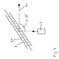
- FIG. 3 shows the movement of soil compacting device 3 in a straight line along a travel path 20 .
- soil compacting device 3 Upon reaching surface boundary 2 , soil compacting device 3 changes its direction of travel, and continues to travel.
- the change of direction in the example shown in FIG. 3 is based on the following rule: soil compacting device 3 always turns to the right and changes its direction angle by 315°, so that travel path 20 encloses an acute turning angle ⁇ of 45°.
- soil compacting device 3 always turns to the right and changes its direction angle by 315°, so that travel path 20 encloses an acute turning angle ⁇ of 45°.
- ⁇ of 45°
- FIG. 4 shows the example of a turning angle ⁇ of 90°.
- an acute turning angle ⁇ has the advantage that surface 1 is compacted relatively quickly even according to a random principle, while at an angle of 90°, in particular if surface boundaries 2 stand at a right angle to one another, there is a danger that vibration plate 3 will always travel the same travel path 20 .
- the surface definition device can be constructed very simply in comparison to the first specific embodiment of the present invention.
- other identification possibilities are conceivable that operate according to a mechanical, optical, magnetic, inductive, or capacitive principle.
- a position detection device not shown in the Figures is provided that can likewise be constructed more simply than the above-explained position detection device 18 of the first specific embodiment of the present invention. This is because it is sufficient for the position detection device to detect only the current position of soil compacting device 3 in the vicinity of a surface boundary 2 , i.e., an approach of soil compacting device 3 to surface boundary 2 . It is not necessary for the position detection device to constantly detect the current position of soil compacting device 3 .
- the position detection device can be equipped with a detector suitable for recognizing the above-defined surface boundaries 2 .
- a motion controller (not shown) that differs from, and is simpler than, the above-described motion controller 8 a / 8 b carries out a modification of a direction of travel corresponding to a predetermined rule.
- a predetermined rule As presented above, it is for example possible always to provide a turning process in the same direction or with a particular angle. Alternatively, randomly selected angles can also be traveled. It must merely be ensured that after changing its direction of travel, soil compacting device 3 no longer has the tendency to cross surface boundary 2 . Should this nonetheless be the case—e.g. given a fixedly predetermined change of direction with a constant angle with particular constellations of surface boundaries 2 —the motion controller would immediately have to take corresponding additional control measures, for example a new change of direction according to the predetermined rules.
- FIG. 4 shows that surface boundary 2 can include a border area 21 that permits a certain tolerance within which soil compacting device 3 must change its direction of travel.
- the soil compacting system according to the present invention preferably has a soil compacting device having stabilization of the travel direction, as is known for example from DE 100 53 446 A1.
- This is for example a vibration plate 3 having vibration exciter 16 that has two shafts 25 , 26 that rotate in opposite directions, on each of which at least one imbalance mass is situated.
- the soil compacting device is equipped with travel direction stabilization corresponding to DE 100 35 446 A1.
- this is not absolutely necessary.
- the soil compacting system to use a conventional soil compacting device, in particular a standard vibration plate, that does not have travel direction stabilization in the sense of DE 100 35 446 A1.
- the motion controller is then responsible for adhering to the travel path, and occasional deviations from the predetermined course are accepted.
- soil compacting devices having more than one vibration exciter can also be used, as is shown for example in FIG. 5 .
- FIG. 5 a schematically shows a top view of a vibration plate with soil contact plate 17 , on which two vibration exciters 27 , 28 are situated so as to be offset to one another.
- a vertical axle 29 is provided between vibration exciters 27 , 28 . It can be seen that when there is a different horizontal exertion of force, vibration exciters 27 , 28 can produce a yaw moment about vertical axle 29 .
- vibration exciters 27 , 28 and, in addition, an additional vibration exciter 30 are situated on base plate 17 of a soil compacting device. Due simply to the fact that all three vibration exciters produce vertical oscillations, it can be seen that such a vibration plate is very well-suited for effective soil compacting. The steerability of the vibration plate is improved by the different directions of action of the vibration exciters—middle vibration exciter 30 is rotated by 90° in relation to the two other vibration exciters 27 , 28 .
- FIG. 5 c a vibration plate is shown having a circular soil contact plate 31 on which two vibration exciters 27 , 28 are situated one over the other and offset by 90° to one another.
- a vibration plate has no preferred direction in the sense of a forward or backward direction of travel, but rather can be adjusted universally in any direction.
- By controlling the phase positions of the imbalance masses of the individual vibration exciters 27 , 28 almost any arbitrary direction of movement of the vibration plate can be realized. This is very advantageous in particular in combination with the soil compacting system according to the present invention, because the vibration plate can change its direction without having to rotate soil contact plate 31 in relation to the soil that is to be compacted.
Abstract
Description
Claims (30)
Applications Claiming Priority (3)
| Application Number | Priority Date | Filing Date | Title |
|---|---|---|---|
| DE10317160A DE10317160A1 (en) | 2003-04-14 | 2003-04-14 | System and method for automated soil compaction |
| DE10317160.6 | 2003-04-14 | ||
| PCT/EP2004/003743 WO2004090232A1 (en) | 2003-04-14 | 2004-04-07 | System and method for the automatic compaction of soil |
Publications (2)
| Publication Number | Publication Date |
|---|---|
| US20070025815A1 US20070025815A1 (en) | 2007-02-01 |
| US7491014B2 true US7491014B2 (en) | 2009-02-17 |
Family
ID=33154213
Family Applications (1)
| Application Number | Title | Priority Date | Filing Date |
|---|---|---|---|
| US10/553,569 Expired - Fee Related US7491014B2 (en) | 2003-04-14 | 2004-04-07 | System and method of the automatic compaction of soil |
Country Status (6)
| Country | Link |
|---|---|
| US (1) | US7491014B2 (en) |
| EP (1) | EP1613812A1 (en) |
| JP (1) | JP2006522881A (en) |
| CN (1) | CN1774545B (en) |
| DE (1) | DE10317160A1 (en) |
| WO (1) | WO2004090232A1 (en) |
Cited By (21)
| Publication number | Priority date | Publication date | Assignee | Title |
|---|---|---|---|---|
| US20070239472A1 (en) * | 2006-04-10 | 2007-10-11 | Deere & Company, A Delaware Corporation | Vehicle area coverage path planning using isometric value regions |
| US20090214300A1 (en) * | 2005-05-25 | 2009-08-27 | Bjorn Birgisson | Devices, systems, and methods for measuring and controlling compactive effort delivered to a soil by a compaction unit |
| US20100272512A1 (en) * | 2009-04-23 | 2010-10-28 | Bomag Gmbh | Multipurpose Compactor and Method for Operating the Multipurpose Compactor |
| US20110150572A1 (en) * | 2009-12-18 | 2011-06-23 | Wirtgen Gmbh | Self-Propelled Civil Engineering Machine And Method Of Controlling A Self-Propelled Civil Engineering Machine |
| US8639420B2 (en) | 2010-12-29 | 2014-01-28 | Caterpillar Inc. | Worksite-management system |
| US8989968B2 (en) | 2012-10-12 | 2015-03-24 | Wirtgen Gmbh | Self-propelled civil engineering machine system with field rover |
| US9096977B2 (en) | 2013-05-23 | 2015-08-04 | Wirtgen Gmbh | Milling machine with location indicator system |
| US9181660B2 (en) | 2012-01-25 | 2015-11-10 | Wirtgen Gmbh | Self-propelled civil engineering machine and method of controlling a civil engineering machine |
| EP2843637B1 (en) | 2013-08-26 | 2016-06-08 | Wacker Neuson Production Americas LLC | System for controlling remote operation of ground working devices |
| US9534348B2 (en) * | 2015-02-16 | 2017-01-03 | Caterpillar Paving Products Inc. | Paver transition mark reduction |
| US9580879B1 (en) | 2016-05-02 | 2017-02-28 | Jason A. Williams | Remotely-operable reciprocating compactor |
| US9719217B2 (en) | 2014-08-28 | 2017-08-01 | Wirtgen Gmbh | Self-propelled construction machine and method for visualizing the working environment of a construction machine moving on a terrain |
| US9896810B2 (en) | 2014-08-28 | 2018-02-20 | Wirtgen Gmbh | Method for controlling a self-propelled construction machine to account for identified objects in a working direction |
| US9915041B2 (en) | 2014-08-28 | 2018-03-13 | Wirtgen Gmbh | Self-propelled construction machine and method for controlling a self-propelled construction machine |
| US9982397B2 (en) | 2012-05-22 | 2018-05-29 | Hamm Ag | Method for planning and implementation of soil compacting processes, especially for asphalt compacting |
| US20190186094A1 (en) * | 2017-12-14 | 2019-06-20 | Caterpillar Paving Products Inc. | System and method for compacting a worksite surface |
| US20190186084A1 (en) * | 2017-12-14 | 2019-06-20 | Caterpillar Paving Products Inc. | System and method for generating a paving material map |
| US11054831B2 (en) | 2018-09-27 | 2021-07-06 | Caterpillar Paving Products Inc. | Automatic site planning for autonomous construction vehicles |
| US11572661B2 (en) | 2019-07-04 | 2023-02-07 | Wirtgen Gmbh | Self-propelled construction machine and method for controlling a self-propelled construction machine |
| US11774965B2 (en) | 2018-08-16 | 2023-10-03 | Wirtgen Gmbh | Slipform paver and method for operating a slipform paver |
| DE102023107838A1 (en) | 2022-04-08 | 2023-10-12 | Caterpillar Paving Products Inc. | CONTROL SYSTEM AND METHOD FOR ACTIVE TRAVEL MONITORING OF A COMPRESSOR |
Families Citing this family (27)
| Publication number | Priority date | Publication date | Assignee | Title |
|---|---|---|---|---|
| EP1705293A1 (en) * | 2005-03-23 | 2006-09-27 | Ammann Aufbereitung AG | Method and device for compacting an area of ground |
| US20070150147A1 (en) * | 2005-12-23 | 2007-06-28 | Rasmussen Terry L | Compactor using compaction value targets |
| DE102006019841B3 (en) * | 2006-04-28 | 2007-12-20 | Moba-Mobile Automation Ag | Apparatus and method for determining the position of a road roller relative to a paver |
| US20070288009A1 (en) * | 2006-06-08 | 2007-12-13 | Steven Brown | Dynamic spinal stabilization device |
| US7731450B2 (en) * | 2006-09-07 | 2010-06-08 | Caterpillar Inc. | Method of operating a compactor machine via path planning based on compaction state data and mapping information |
| DE102006050359A1 (en) * | 2006-10-25 | 2008-04-30 | Wacker Construction Equipment Ag | Soil compacting system, comprises soil compacting device and documentation device, where soil compacting device is equipped with oscillation excitation device and documentation device with process data capturing device and evaluation device |
| DE102007018743A1 (en) * | 2007-04-22 | 2008-10-23 | Bomag Gmbh | Method and system for controlling compaction machines |
| DE102007053311A1 (en) * | 2007-06-21 | 2008-12-24 | Robert Bosch Gmbh | Drive system for a robotic vehicle |
| CN102023767B (en) * | 2009-09-14 | 2015-01-14 | 义隆电子股份有限公司 | Improvement method for capacitive touch pad edge positioning |
| DE102010021335A1 (en) * | 2010-05-22 | 2011-11-24 | Frank Baldinger | Method and device for producing a pipe bedding |
| DE102010023461A1 (en) | 2010-06-11 | 2011-12-15 | Wacker Neuson Se | Device and method for determining the position of a working device |
| US9066465B2 (en) * | 2013-02-20 | 2015-06-30 | Deere & Company | Soil compaction reduction system and method |
| CN104343072A (en) * | 2013-08-09 | 2015-02-11 | 陕西公众智能科技有限公司 | Monitoring device for road roller |
| US9739019B1 (en) * | 2014-06-13 | 2017-08-22 | Gomaco Corporation | Bridge paving device |
| DE102015122149A1 (en) * | 2015-12-17 | 2017-06-22 | Ammann Schweiz Ag | Method for the autonomous operation of a compacting device |
| CN107090823B (en) * | 2016-02-18 | 2019-04-23 | 天宝公司 | The dynamic compaction system of automation |
| DE102016004197A1 (en) * | 2016-04-06 | 2017-10-12 | Bomag Gmbh | Method for operating a ground milling machine, ground milling machine with a handset and handset for a ground milling machine |
| CN110325686A (en) * | 2017-04-25 | 2019-10-11 | 深圳市元征科技股份有限公司 | Control method and device, the storage medium of road roller automatic job |
| DE102017110471A1 (en) | 2017-05-15 | 2018-11-15 | Claas Kommanditgesellschaft auf Aktien mbH | Method of compacting crops in a silo |
| DE102018104568A1 (en) * | 2018-02-28 | 2019-08-29 | Wacker Neuson Produktion GmbH & Co. KG | System and method for automated soil compaction |
| US10563362B2 (en) | 2018-06-01 | 2020-02-18 | Caterpillar Paving Products Inc. | System and method for paving machine control |
| JP7022659B2 (en) * | 2018-06-22 | 2022-02-18 | 株式会社安藤・間 | Career change route determination system, self-driving construction machine, and course change route determination program |
| DE102019219758A1 (en) * | 2019-12-16 | 2021-06-17 | Zf Friedrichshafen Ag | Vibratory plate, subsoil compaction system, method of subsoil compaction |
| CN111236010B (en) * | 2020-01-17 | 2021-09-24 | 三一汽车制造有限公司 | Operation control method and system for unmanned road roller group |
| KR102339325B1 (en) * | 2021-05-24 | 2021-12-15 | 경북대학교 산학협력단 | Rotational flattening and compaction automation system |
| DE102021002728A1 (en) | 2021-05-26 | 2022-12-01 | Bomag Gmbh | METHOD OF CONTROLLING THE TRAVEL OPERATION OF A SELF-PROPELLED SOIL COMPACTION MACHINE AND SOIL COMPACTION MACHINE |
| CN113944085B (en) * | 2021-10-19 | 2022-09-02 | 广东宏茂建设管理有限公司 | Full-automatic ramming machine and control method thereof |
Citations (19)
| Publication number | Priority date | Publication date | Assignee | Title |
|---|---|---|---|---|
| US4600999A (en) * | 1982-07-13 | 1986-07-15 | Kubota, Ltd. | Automatic running work vehicle |
| FR2697098A1 (en) | 1992-10-07 | 1994-04-22 | Sn Eno | Method for controlling the movement of an autonomous electric machine with random displacement, and suitable electric machine. |
| EP0761886A1 (en) | 1995-08-21 | 1997-03-12 | Etat Francais Represente Par Le Laboratoire Central Des Ponts Et Chaussees | Method of and auxiliary equipment for guiding a compaction machine |
| US5646844A (en) * | 1994-04-18 | 1997-07-08 | Caterpillar Inc. | Method and apparatus for real-time monitoring and coordination of multiple geography altering machines on a work site |
| US6088644A (en) * | 1998-08-12 | 2000-07-11 | Caterpillar Inc. | Method and apparatus for determining a path to be traversed by a mobile machine |
| US6113309A (en) * | 1996-08-20 | 2000-09-05 | Hollon; Edmund D. | Uniform compaction of asphalt concrete |
| US6213681B1 (en) * | 1997-07-23 | 2001-04-10 | Wacker-Werke Gmbh & Co., Kg | Soil compacting device with adjustable vibration properties |
| US6243039B1 (en) * | 1998-04-21 | 2001-06-05 | Mci Communications Corporation | Anytime/anywhere child locator system |
| US6263750B1 (en) * | 1997-05-05 | 2001-07-24 | Wacker-Werke Gmbh & Co. Kg | Device for generating directed vibrations |
| US6282362B1 (en) * | 1995-11-07 | 2001-08-28 | Trimble Navigation Limited | Geographical position/image digital recording and display system |
| US6287048B1 (en) * | 1996-08-20 | 2001-09-11 | Edmund D. Hollon | Uniform compaction of asphalt concrete |
| DE10053446A1 (en) | 2000-10-27 | 2002-06-06 | Wacker Werke Kg | Mobile soil compacting device with directional stabilization |
| US20050086211A1 (en) * | 2000-06-22 | 2005-04-21 | Yaron Mayer | System and method for searching, finding and contacting dates on the Internet in instant messaging networks and/or in other methods that enable immediate finding and creating immediate contact |
| US20050085241A1 (en) * | 2001-01-19 | 2005-04-21 | Microsoft Corporation | Information management and processing in a wireless network |
| US20050258240A1 (en) * | 2004-03-30 | 2005-11-24 | Honeywell International Inc. | Identifying the Location of an Asset |
| US20070025306A1 (en) * | 2005-08-01 | 2007-02-01 | Cisco Technology, Inc. | Method and system for dynamic assignment of wireless LAN access point identity |
| US7256388B2 (en) * | 2005-02-04 | 2007-08-14 | Novariant, Inc. | System and method for interactive selection of agricultural vehicle guide paths through a graphical user interface other than moving the vehicle |
| USRE39834E1 (en) * | 1998-10-27 | 2007-09-11 | Michigan Technological University | Apparatus and method for three-dimensional contouring |
| US7354221B2 (en) * | 2005-02-28 | 2008-04-08 | Caterpillar Inc. | Self-propelled plate compactor having linear excitation |
Family Cites Families (15)
| Publication number | Priority date | Publication date | Assignee | Title |
|---|---|---|---|---|
| DE7818542U1 (en) | 1978-06-21 | 1982-10-14 | Wacker-Werke Gmbh & Co Kg, 8077 Reichertshofen | Vibration exciter for disc compressors |
| JP2604629B2 (en) * | 1988-12-20 | 1997-04-30 | 株式会社間組 | Erecting material compaction device |
| JP2722350B2 (en) * | 1989-03-31 | 1998-03-04 | 不動建設株式会社 | Construction management method in soil compaction method such as embankment |
| JP2894898B2 (en) * | 1992-06-16 | 1999-05-24 | 株式会社島津製作所 | Pavement construction machine data collection device |
| JP2611919B2 (en) * | 1993-06-23 | 1997-05-21 | 建設省土木研究所長 | Vibration roller vibratory force control device |
| SE502079C2 (en) | 1993-10-14 | 1995-08-07 | Thurner Geodynamik Ab | Control of a packing machine measuring the properties of the substrate |
| IT1267730B1 (en) * | 1994-06-14 | 1997-02-07 | Zeltron Spa | PROGRAMMABLE REMOTE CONTROL SYSTEM FOR A VEHICLE |
| JP3018275B2 (en) * | 1995-03-27 | 2000-03-13 | 山陰建設工業株式会社 | Civil leveling equipment |
| JP2911398B2 (en) * | 1995-11-22 | 1999-06-23 | 株式会社熊谷組 | Compaction monitoring device |
| JP3341142B2 (en) * | 1996-01-08 | 2002-11-05 | 三井ホーム株式会社 | Mobile soil compaction machine |
| ATE195157T1 (en) | 1996-10-21 | 2000-08-15 | Ammann Verdichtung Ag | METHOD FOR MEASURING MECHANICAL DATA OF A SOIL AS WELL AS ITS COMPACTION AND MEASURING OR SOIL COMPACTION DEVICE |
| JPH10219614A (en) * | 1997-02-04 | 1998-08-18 | Fujita Corp | Automatic traveling control method of vehicle and its system |
| SE510524C2 (en) * | 1997-09-19 | 1999-05-31 | Electrolux Ab | Electronic demarcation system |
| DE10046336B4 (en) | 2000-09-19 | 2005-03-31 | Wacker Construction Equipment Ag | Soil compacting device with vibration exciter and method for controlling the vibration exciter |
| DE10116526B4 (en) * | 2001-04-03 | 2004-04-01 | Wacker Construction Equipment Ag | Remote control device for self-propelled tools |
-
2003
- 2003-04-14 DE DE10317160A patent/DE10317160A1/en not_active Ceased
-
2004
- 2004-04-07 US US10/553,569 patent/US7491014B2/en not_active Expired - Fee Related
- 2004-04-07 CN CN2004800095631A patent/CN1774545B/en not_active Expired - Fee Related
- 2004-04-07 JP JP2006505055A patent/JP2006522881A/en active Pending
- 2004-04-07 EP EP04726161A patent/EP1613812A1/en not_active Withdrawn
- 2004-04-07 WO PCT/EP2004/003743 patent/WO2004090232A1/en active Application Filing
Patent Citations (20)
| Publication number | Priority date | Publication date | Assignee | Title |
|---|---|---|---|---|
| US4600999A (en) * | 1982-07-13 | 1986-07-15 | Kubota, Ltd. | Automatic running work vehicle |
| FR2697098A1 (en) | 1992-10-07 | 1994-04-22 | Sn Eno | Method for controlling the movement of an autonomous electric machine with random displacement, and suitable electric machine. |
| US5646844A (en) * | 1994-04-18 | 1997-07-08 | Caterpillar Inc. | Method and apparatus for real-time monitoring and coordination of multiple geography altering machines on a work site |
| EP0761886A1 (en) | 1995-08-21 | 1997-03-12 | Etat Francais Represente Par Le Laboratoire Central Des Ponts Et Chaussees | Method of and auxiliary equipment for guiding a compaction machine |
| US6282362B1 (en) * | 1995-11-07 | 2001-08-28 | Trimble Navigation Limited | Geographical position/image digital recording and display system |
| US6287048B1 (en) * | 1996-08-20 | 2001-09-11 | Edmund D. Hollon | Uniform compaction of asphalt concrete |
| US6113309A (en) * | 1996-08-20 | 2000-09-05 | Hollon; Edmund D. | Uniform compaction of asphalt concrete |
| US6263750B1 (en) * | 1997-05-05 | 2001-07-24 | Wacker-Werke Gmbh & Co. Kg | Device for generating directed vibrations |
| US6213681B1 (en) * | 1997-07-23 | 2001-04-10 | Wacker-Werke Gmbh & Co., Kg | Soil compacting device with adjustable vibration properties |
| US6243039B1 (en) * | 1998-04-21 | 2001-06-05 | Mci Communications Corporation | Anytime/anywhere child locator system |
| US6088644A (en) * | 1998-08-12 | 2000-07-11 | Caterpillar Inc. | Method and apparatus for determining a path to be traversed by a mobile machine |
| USRE39834E1 (en) * | 1998-10-27 | 2007-09-11 | Michigan Technological University | Apparatus and method for three-dimensional contouring |
| US20050086211A1 (en) * | 2000-06-22 | 2005-04-21 | Yaron Mayer | System and method for searching, finding and contacting dates on the Internet in instant messaging networks and/or in other methods that enable immediate finding and creating immediate contact |
| US20040022582A1 (en) * | 2000-10-27 | 2004-02-05 | Georg Sick | Mobile soil compacting device whose direction of travel is stabilized |
| DE10053446A1 (en) | 2000-10-27 | 2002-06-06 | Wacker Werke Kg | Mobile soil compacting device with directional stabilization |
| US20050085241A1 (en) * | 2001-01-19 | 2005-04-21 | Microsoft Corporation | Information management and processing in a wireless network |
| US20050258240A1 (en) * | 2004-03-30 | 2005-11-24 | Honeywell International Inc. | Identifying the Location of an Asset |
| US7256388B2 (en) * | 2005-02-04 | 2007-08-14 | Novariant, Inc. | System and method for interactive selection of agricultural vehicle guide paths through a graphical user interface other than moving the vehicle |
| US7354221B2 (en) * | 2005-02-28 | 2008-04-08 | Caterpillar Inc. | Self-propelled plate compactor having linear excitation |
| US20070025306A1 (en) * | 2005-08-01 | 2007-02-01 | Cisco Technology, Inc. | Method and system for dynamic assignment of wireless LAN access point identity |
Cited By (41)
| Publication number | Priority date | Publication date | Assignee | Title |
|---|---|---|---|---|
| US20090214300A1 (en) * | 2005-05-25 | 2009-08-27 | Bjorn Birgisson | Devices, systems, and methods for measuring and controlling compactive effort delivered to a soil by a compaction unit |
| US20070239472A1 (en) * | 2006-04-10 | 2007-10-11 | Deere & Company, A Delaware Corporation | Vehicle area coverage path planning using isometric value regions |
| US20100272512A1 (en) * | 2009-04-23 | 2010-10-28 | Bomag Gmbh | Multipurpose Compactor and Method for Operating the Multipurpose Compactor |
| US8672582B2 (en) * | 2009-04-23 | 2014-03-18 | Bomag Gmbh | Multipurpose compactor and method for operating the multipurpose compactor |
| US20110150572A1 (en) * | 2009-12-18 | 2011-06-23 | Wirtgen Gmbh | Self-Propelled Civil Engineering Machine And Method Of Controlling A Self-Propelled Civil Engineering Machine |
| US8388263B2 (en) * | 2009-12-18 | 2013-03-05 | Wirtgen Gmbh | Self-propelled civil engineering machine and method of controlling a self-propelled civil engineering machine |
| US8613566B2 (en) | 2009-12-18 | 2013-12-24 | Wirtgen Gmbh | Self-propelled civil engineering machine and method of controlling a self-propelled civil engineering machine |
| US8888402B2 (en) | 2009-12-18 | 2014-11-18 | Wirtgen Gmbh | Self-propelled civil engineering machine and method of controlling a self-propelled civil engineering machine |
| US8639420B2 (en) | 2010-12-29 | 2014-01-28 | Caterpillar Inc. | Worksite-management system |
| US9598080B2 (en) | 2012-01-25 | 2017-03-21 | Wirtgen Gmbh | Self-propelled civil engineering machine and method of controlling a civil engineering machine |
| US9181660B2 (en) | 2012-01-25 | 2015-11-10 | Wirtgen Gmbh | Self-propelled civil engineering machine and method of controlling a civil engineering machine |
| US9982397B2 (en) | 2012-05-22 | 2018-05-29 | Hamm Ag | Method for planning and implementation of soil compacting processes, especially for asphalt compacting |
| US11313679B2 (en) | 2012-10-12 | 2022-04-26 | Wirtgen Gmbh | Self-propelled civil engineering machine system with field rover |
| US11761763B2 (en) | 2012-10-12 | 2023-09-19 | Wirtgen Gmbh | Self-propelled civil engineering machine system with field rover |
| US10746546B2 (en) | 2012-10-12 | 2020-08-18 | Wirtgen Gmbh | Self-propelled civil engineering machine system with field rover |
| US10180322B2 (en) | 2012-10-12 | 2019-01-15 | Wirtgen Gmbh | Self-propelled civil engineering machine system with field rover |
| US8989968B2 (en) | 2012-10-12 | 2015-03-24 | Wirtgen Gmbh | Self-propelled civil engineering machine system with field rover |
| US9359729B2 (en) | 2013-05-23 | 2016-06-07 | Wirtgen Gmbh | Milling machine with location indicator system |
| US9096977B2 (en) | 2013-05-23 | 2015-08-04 | Wirtgen Gmbh | Milling machine with location indicator system |
| US9970164B2 (en) | 2013-05-23 | 2018-05-15 | Wirtgen Gmbh | Milling machine with location indicator system |
| EP2843637B1 (en) | 2013-08-26 | 2016-06-08 | Wacker Neuson Production Americas LLC | System for controlling remote operation of ground working devices |
| US9650062B2 (en) | 2013-08-26 | 2017-05-16 | Wacker Neuson Production Americas Llc | System for controlling remote operation of ground working devices |
| US9915041B2 (en) | 2014-08-28 | 2018-03-13 | Wirtgen Gmbh | Self-propelled construction machine and method for controlling a self-propelled construction machine |
| US11072893B2 (en) | 2014-08-28 | 2021-07-27 | Wirtgen Gmbh | Self-propelled construction machine and method for controlling a self-propelled construction machine |
| US10273642B2 (en) | 2014-08-28 | 2019-04-30 | Wirtgen Gmbh | Self-propelled construction machine and method for controlling a self-propelled construction machine |
| US11619011B2 (en) | 2014-08-28 | 2023-04-04 | Wirtgen Gmbh | Self-propelled construction machine and method for controlling a self-propelled construction machine |
| US9896810B2 (en) | 2014-08-28 | 2018-02-20 | Wirtgen Gmbh | Method for controlling a self-propelled construction machine to account for identified objects in a working direction |
| US9719217B2 (en) | 2014-08-28 | 2017-08-01 | Wirtgen Gmbh | Self-propelled construction machine and method for visualizing the working environment of a construction machine moving on a terrain |
| US9534348B2 (en) * | 2015-02-16 | 2017-01-03 | Caterpillar Paving Products Inc. | Paver transition mark reduction |
| US9580879B1 (en) | 2016-05-02 | 2017-02-28 | Jason A. Williams | Remotely-operable reciprocating compactor |
| US10669678B2 (en) * | 2017-12-14 | 2020-06-02 | Caterpillar Paving Products Inc. | System and method for generating a paving material map |
| US10640943B2 (en) * | 2017-12-14 | 2020-05-05 | Caterpillar Paving Products Inc. | System and method for compacting a worksite surface |
| US10920381B2 (en) | 2017-12-14 | 2021-02-16 | Caterpillar Paving Products Inc. | System and method for generating a paving material map |
| US20190186084A1 (en) * | 2017-12-14 | 2019-06-20 | Caterpillar Paving Products Inc. | System and method for generating a paving material map |
| US11111644B2 (en) | 2017-12-14 | 2021-09-07 | Caterpillar Paving Products Inc. | System and method for performing operations on a worksite surface |
| US20190186094A1 (en) * | 2017-12-14 | 2019-06-20 | Caterpillar Paving Products Inc. | System and method for compacting a worksite surface |
| US11629472B2 (en) | 2017-12-14 | 2023-04-18 | Caterpillar Paving Products Inc. | System and method for performing operations on a worksite surface |
| US11774965B2 (en) | 2018-08-16 | 2023-10-03 | Wirtgen Gmbh | Slipform paver and method for operating a slipform paver |
| US11054831B2 (en) | 2018-09-27 | 2021-07-06 | Caterpillar Paving Products Inc. | Automatic site planning for autonomous construction vehicles |
| US11572661B2 (en) | 2019-07-04 | 2023-02-07 | Wirtgen Gmbh | Self-propelled construction machine and method for controlling a self-propelled construction machine |
| DE102023107838A1 (en) | 2022-04-08 | 2023-10-12 | Caterpillar Paving Products Inc. | CONTROL SYSTEM AND METHOD FOR ACTIVE TRAVEL MONITORING OF A COMPRESSOR |
Also Published As
| Publication number | Publication date |
|---|---|
| JP2006522881A (en) | 2006-10-05 |
| CN1774545B (en) | 2010-04-28 |
| DE10317160A1 (en) | 2004-11-18 |
| WO2004090232A1 (en) | 2004-10-21 |
| CN1774545A (en) | 2006-05-17 |
| US20070025815A1 (en) | 2007-02-01 |
| EP1613812A1 (en) | 2006-01-11 |
Similar Documents
| Publication | Publication Date | Title |
|---|---|---|
| US7491014B2 (en) | System and method of the automatic compaction of soil | |
| US11079755B2 (en) | System and method for autonomous operation of a machine | |
| US10001783B2 (en) | Method for controlling a work train | |
| CN110949371B (en) | Autonomous field planning for autonomous construction vehicles | |
| EP3259971B1 (en) | Travel support system and work vehicle | |
| CN101668902B (en) | Machine with automated blade positioning system | |
| JP3638198B2 (en) | Control system and control method | |
| US6846128B2 (en) | Mobile soil compacting device whose direction of travel is stabilized | |
| KR101879247B1 (en) | The Working Path Setting Method for Automatic Driving Agricultural Machine | |
| US11761155B2 (en) | Self-propelled milling machine, as well as method for controlling a self-propelled milling machine | |
| CN111236017B (en) | Automatic driving control method and system of paver and paver | |
| JP2006522881A5 (en) | ||
| CN113005868B (en) | Method for milling traffic areas using a milling drum and milling machine for carrying out the method | |
| CN110777629A (en) | System and method for cold planer control | |
| WO2019167204A1 (en) | Control device, work machine, and program | |
| EP3176542A1 (en) | Odometer for a vehicle | |
| US11555278B2 (en) | Autowidth input for paving operations | |
| US20100139424A1 (en) | Vibrator for a ground compacting apparatus | |
| CN115506209A (en) | System and method for marking boundaries in defining autonomous work sites | |
| JPH10212705A (en) | Vibrational roller automatic operating system | |
| DE102004014963B3 (en) | Trowels with directional stabilization | |
| CN116163184A (en) | Control system and method for defining and generating a compactor operating region | |
| JP2022102956A (en) | Control system for work vehicle | |
| CN116356640A (en) | Compaction mode adjustment for automated compaction | |
| KR20220092789A (en) | Control system of working vehicle |
Legal Events
| Date | Code | Title | Description |
|---|---|---|---|
| AS | Assignment |
Owner name: WACKER CONSTRUCTION EQUIPMENT AG, GERMANY Free format text: ASSIGNMENT OF ASSIGNORS INTEREST;ASSIGNOR:SICK, MR. GEORG;REEL/FRAME:017751/0741 Effective date: 20051007 |
|
| AS | Assignment |
Owner name: WACKER NEUSON SE,GERMANY Free format text: CHANGE OF NAME;ASSIGNOR:WACKER CONSTRUCTION EQUIPMENT AG;REEL/FRAME:024515/0259 Effective date: 20091002 Owner name: WACKER NEUSON SE, GERMANY Free format text: CHANGE OF NAME;ASSIGNOR:WACKER CONSTRUCTION EQUIPMENT AG;REEL/FRAME:024515/0259 Effective date: 20091002 |
|
| AS | Assignment |
Owner name: WACKER NEUSON PRODUKTION GMBH & CO. KG, GERMANY Free format text: NUNC PRO TUNC ASSIGNMENT;ASSIGNOR:WACKER NEUSON SE;REEL/FRAME:026955/0859 Effective date: 20110829 |
|
| FPAY | Fee payment |
Year of fee payment: 4 |
|
| REMI | Maintenance fee reminder mailed | ||
| LAPS | Lapse for failure to pay maintenance fees | ||
| STCH | Information on status: patent discontinuation |
Free format text: PATENT EXPIRED DUE TO NONPAYMENT OF MAINTENANCE FEES UNDER 37 CFR 1.362 |
|
| FP | Lapsed due to failure to pay maintenance fee |
Effective date: 20170217 |