US7501789B2 - Solar powered battery charger with voltage regulation circuit apparatus and method - Google Patents
Solar powered battery charger with voltage regulation circuit apparatus and method Download PDFInfo
- Publication number
- US7501789B2 US7501789B2 US11/298,663 US29866305A US7501789B2 US 7501789 B2 US7501789 B2 US 7501789B2 US 29866305 A US29866305 A US 29866305A US 7501789 B2 US7501789 B2 US 7501789B2
- Authority
- US
- United States
- Prior art keywords
- voltage
- output port
- battery
- ratio
- power
- Prior art date
- Legal status (The legal status is an assumption and is not a legal conclusion. Google has not performed a legal analysis and makes no representation as to the accuracy of the status listed.)
- Expired - Fee Related
Links
Images


Classifications
-
- H—ELECTRICITY
- H02—GENERATION; CONVERSION OR DISTRIBUTION OF ELECTRIC POWER
- H02J—CIRCUIT ARRANGEMENTS OR SYSTEMS FOR SUPPLYING OR DISTRIBUTING ELECTRIC POWER; SYSTEMS FOR STORING ELECTRIC ENERGY
- H02J7/00—Circuit arrangements for charging or depolarising batteries or for supplying loads from batteries
- H02J7/34—Parallel operation in networks using both storage and other dc sources, e.g. providing buffering
- H02J7/35—Parallel operation in networks using both storage and other dc sources, e.g. providing buffering with light sensitive cells
Definitions
- the present invention relates to a solar powered battery charger with voltage regulation circuit apparatus and method.
- Car batteries are prone to self discharge and also since there are onboard electronics that work even when the car is stopped (maybe 70 milli-amps), batteries that are left in cars that are not used will discharge after long periods.
- Disconnecting the battery only partially addresses the problem since it does not prevent self-discharge. Additionally, it brings new problems as some electronics will reset themselves and will need reprogramming. Further, it is very likely that the battery will later be reconnected which involves some labor.
- a battery charger comprising: an input port for receiving electrical power from a solar panel; an output port for providing electrical power to a battery; and a power regulation circuit electrically coupled to the input port, the power regulation circuit electrically coupled to the output port and for monitoring a voltage thereon, the power regulation circuit having a first state in which electrical power is provided to the output port and a second state in which electrical power is not provided to the output port, the power regulation circuit for remaining in a first state when the voltage at the output port is below a threshold voltage and for remaining in the second state when the voltage at the output port is above the threshold voltage.
- a method of recharging a car battery comprising the steps of: receiving electrical power from a photovoltaic cell; monitoring a voltage from the car battery using a power regulation circuit, the voltage indicative of a level of charge of the car battery; and providing the received electrical power through the power regulation circuit to the car battery in dependence upon the monitored voltage.
- a solar panel comprising: a photovoltaic cell; a frame mechanically coupled to the photovoltaic cell; and a shock absorbing member having a first portion fixedly coupled to one of the frame and the photovoltaic cell, and a second other portion for mechanically coupling to a vehicle, the shock absorbing member for reducing the intensity of mechanical shocks imparted to the photovoltaic cell.
- FIG. 1 is a perspective view of the battery charger according to a preferred embodiment of the present invention
- FIG. 2 is a bottom view of the battery charger according to the preferred embodiment of the present invention.
- FIG. 3 is an enlarged view of the cigarette lighter adapter of the battery charger according to the preferred embodiment of the present invention.
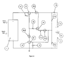
- FIG. 4 is an electrical circuit designed to prevent an overcharging of a car battery and is consistent with a protection circuit according to the preferred embodiment of the present invention.
- a system according to the invention comprises an electronic circuit designed to couple to a photovoltaic cell and an electrical connection of a car.
- the electronic circuit acts to monitor a level of charge in the battery and supply power to the battery when the level of charge of the battery is below a threshold.
- the charger 100 comprises a solar panel 1 enclosed in a suitable frame 2 for support and protection.
- the solar panel converts light from ambient light sources, such as the sun, into electrical energy that is transmitted through the wire 3 to a male car cigarette lighter adaptor (CLA) 4 .
- CLA car cigarette lighter adaptor
- the suction cups 5 are designed to prevent the frame 2 from slipping, for example when the vehicle is being moved on a ship or a train.
- the same suction cups 5 are optionally used to place the charger in a window, such as affixed to a windshield of the car.
- the suction cups are optionally fairly large and soft so as to absorb shock should the unit be dropped.
- the suction cups 5 comprise ridges 7 that are intended to protect the panel against shock should it be dropped or in the case of a car collision.
- the preferred embodiment of the invention is shown having rubber bumpers 6 attached to the frame to absorb external shocks.
- the rubber bumpers 6 and the ridges 7 are important to the preferred embodiment of the invention since they help to partially mechanically isolate the fragile solar panel from large shock loads, such as a car collision.
- Making the charger 100 more robust allows the solar charger 100 to be safely used in cars where safety standards are high and require anti-breakage or anti-shattering features for their accessories.
- the charger according to the preferred embodiment of the invention comprises an electrical circuit (not shown) that is designed to prevent overcharging of a car battery when the charger is electrically coupled to the electrical system of a car. This circuit acts to prevent an overcharging of a standard car battery and thereby avoids limitations of the prior art solar battery rechargers for cars.
- FIG. 2 a bottom view of the preferred embodiment of the invention is shown. This view clearly shows the suction cups 5 that support the panel adhering to a surface from the bottom side.
- the bottom side protects the fragile solar panel 1 by the addition of a plastic rear piece 8 .
- the CLA 4 comprises electronics and connectors that support and provide a regulated power supply to the car battery.
- the wire 3 is coupled to the solar panel 1 .
- the output end 9 is designed to fit into the female receptacle of a car CLA plug and comprises of negative contacts 11 and a positive contact 12 .
- FIG. 4 a circuit diagram of a power regulation circuit or an electrical circuit intended to prevent overcharging of a car battery is shown.
- the circuit shown in FIG. 4 is optionally incorporated within the CLA 4 of the preferred embodiment of the invention.
- the circuit is designed to receive electrical energy from the solar panel 1 and its output current is provided to the car battery 13 via negative contact 11 and positive contact 12 .
- Power to the car battery goes through power transistor 14 .
- Collector-base resistor 15 serves to provide limited current into a base of power transistor 14 for operation and also sets current for operation of the comparator/switch IC 16 .
- the comparator/switch IC 16 has an internal voltage reference.
- the battery voltage is fed back into the circuit through voltage divider resistors 17 . a , 17 . b and 17 . c at node 18 . If this voltage is lower than the internal reference voltage, the comparator/switch IC 16 is in the off position and the power resistor 14 is biased to the “on” state by the current available from the solar panel 1 through collector-base resistor 15 . If the battery voltage fed back at point 18 is higher than the internal reference voltage, the comparator/switch IC 16 is in the on position and the power transistor 14 is biased to an “off’ state or second state in which current is no longer allowed to flow from the solar panel 1 into the battery 13 .
- the resume charge switch transistor 19 is biased to an “on” state with the current that flows through base resistor 20 .
- the comparator/switch IC 16 back into the “off’ position the battery discharges down to a lower voltage than what was needed to turn the switch to the “on” state. In this way, a hysterisis window is created between battery charge cut off threshold and resume charge cut threshold in voltages. The cut in voltage is lower than the cut out voltage. Protection diodes 20 . a , 20 . b and 20 . c and stability capacitor 21 and fuse 22 complete the circuit.
- a predetermined function may be incorporated with the power regulation circuit and may generate an output voltage to be compared with the internal reference voltage.
- a temperature monitoring circuit (not shown) for monitoring temperature (i.e. monitoring the battery temperature) and providing temperature data may be integrally combined or in communication with the predetermined function, thus the output of the predetermined function may vary accordingly with change in temperature data. Therefore, an “on” or “off” state of the power regulation circuit may be determined based on both the voltage state of the battery and temperature data.
Abstract
Description
Claims (15)
Priority Applications (1)
| Application Number | Priority Date | Filing Date | Title |
|---|---|---|---|
| US11/298,663 US7501789B2 (en) | 2004-12-10 | 2005-12-12 | Solar powered battery charger with voltage regulation circuit apparatus and method |
Applications Claiming Priority (2)
| Application Number | Priority Date | Filing Date | Title |
|---|---|---|---|
| US63455104P | 2004-12-10 | 2004-12-10 | |
| US11/298,663 US7501789B2 (en) | 2004-12-10 | 2005-12-12 | Solar powered battery charger with voltage regulation circuit apparatus and method |
Publications (2)
| Publication Number | Publication Date |
|---|---|
| US20060267543A1 US20060267543A1 (en) | 2006-11-30 |
| US7501789B2 true US7501789B2 (en) | 2009-03-10 |
Family
ID=37462501
Family Applications (1)
| Application Number | Title | Priority Date | Filing Date |
|---|---|---|---|
| US11/298,663 Expired - Fee Related US7501789B2 (en) | 2004-12-10 | 2005-12-12 | Solar powered battery charger with voltage regulation circuit apparatus and method |
Country Status (1)
| Country | Link |
|---|---|
| US (1) | US7501789B2 (en) |
Cited By (2)
| Publication number | Priority date | Publication date | Assignee | Title |
|---|---|---|---|---|
| US20150253791A1 (en) * | 2014-03-10 | 2015-09-10 | Schneider Electric Industries Sas | Power supply device and method for wireless sensor unit |
| US20160079805A1 (en) * | 2014-09-12 | 2016-03-17 | Robert Reynolds | Ideal diode |
Families Citing this family (7)
| Publication number | Priority date | Publication date | Assignee | Title |
|---|---|---|---|---|
| US20090079385A1 (en) * | 2007-09-21 | 2009-03-26 | Msr Innovations Inc. | Solar powered battery charger using switch capacitor voltage converters |
| US20100207571A1 (en) * | 2009-02-19 | 2010-08-19 | SunCore Corporation | Solar chargeable battery for portable devices |
| US8319470B2 (en) * | 2010-02-12 | 2012-11-27 | Suncore, Inc. | Stand alone solar battery charger |
| US8355805B2 (en) | 2011-03-08 | 2013-01-15 | D. Light Design, Inc. | Systems and methods for activation and deactivation of appliances |
| WO2013044465A1 (en) * | 2011-09-28 | 2013-04-04 | Chung Yuan Kai | Portable solar charger |
| EP3118965B1 (en) * | 2015-07-15 | 2019-10-30 | Hyundai Motor Company | Apparatus for controlling supply of power of battery |
| FR3066352B1 (en) * | 2017-05-15 | 2020-10-09 | Ateq | PORTABLE DEVICE WITH GRIP ELEMENT |
Citations (5)
| Publication number | Priority date | Publication date | Assignee | Title |
|---|---|---|---|---|
| US4453119A (en) * | 1980-01-21 | 1984-06-05 | Terry Staler | Electrical charging control apparatus and method, and solar to electrical energy conversion apparatus incorporating such charging control apparatus |
| US5221891A (en) * | 1989-07-31 | 1993-06-22 | Intermatic Incorporated | Control circuit for a solar-powered rechargeable power source and load |
| US6046570A (en) * | 1997-03-07 | 2000-04-04 | Interplex Energy Ltd. | Waveform generator and control circuit |
| US20060028166A1 (en) * | 2003-02-25 | 2006-02-09 | Vhf Technologies Sa | Photovoltaic device |
| US20060073044A1 (en) * | 2004-09-24 | 2006-04-06 | Lui Wing H | Car window circulator fan driven by solar generator |
-
2005
- 2005-12-12 US US11/298,663 patent/US7501789B2/en not_active Expired - Fee Related
Patent Citations (5)
| Publication number | Priority date | Publication date | Assignee | Title |
|---|---|---|---|---|
| US4453119A (en) * | 1980-01-21 | 1984-06-05 | Terry Staler | Electrical charging control apparatus and method, and solar to electrical energy conversion apparatus incorporating such charging control apparatus |
| US5221891A (en) * | 1989-07-31 | 1993-06-22 | Intermatic Incorporated | Control circuit for a solar-powered rechargeable power source and load |
| US6046570A (en) * | 1997-03-07 | 2000-04-04 | Interplex Energy Ltd. | Waveform generator and control circuit |
| US20060028166A1 (en) * | 2003-02-25 | 2006-02-09 | Vhf Technologies Sa | Photovoltaic device |
| US20060073044A1 (en) * | 2004-09-24 | 2006-04-06 | Lui Wing H | Car window circulator fan driven by solar generator |
Cited By (4)
| Publication number | Priority date | Publication date | Assignee | Title |
|---|---|---|---|---|
| US20150253791A1 (en) * | 2014-03-10 | 2015-09-10 | Schneider Electric Industries Sas | Power supply device and method for wireless sensor unit |
| US9817413B2 (en) * | 2014-03-10 | 2017-11-14 | Schneider Electric Industries Sas | Power supply device and method for wireless sensor unit |
| US20160079805A1 (en) * | 2014-09-12 | 2016-03-17 | Robert Reynolds | Ideal diode |
| US9515518B2 (en) * | 2014-09-12 | 2016-12-06 | Robert Reynolds | Ideal diode |
Also Published As
| Publication number | Publication date |
|---|---|
| US20060267543A1 (en) | 2006-11-30 |
Similar Documents
| Publication | Publication Date | Title |
|---|---|---|
| US7501789B2 (en) | Solar powered battery charger with voltage regulation circuit apparatus and method | |
| CN110574217B (en) | BMS awakens equipment, and including BMS and group battery of this BMS awakens equipment up | |
| US8189305B2 (en) | Auxiliary battery system | |
| US6384573B1 (en) | Compact lightweight auxiliary multifunctional reserve battery engine starting system (and methods) | |
| US9506446B2 (en) | Mobile power bank | |
| US7839019B2 (en) | Multipurpose portable storage and supply system | |
| US6507172B2 (en) | Universal serial bus powered battery charger | |
| US6337557B1 (en) | External universal battery charging apparatus and method | |
| US20170106763A1 (en) | Electric vehicle automatic charging station | |
| US5017856A (en) | Battery charging system | |
| KR102247393B1 (en) | Battery pack and method for controlling thereof | |
| US8421400B1 (en) | Solar-powered battery charger and related system and method | |
| JP3931446B2 (en) | Battery charge state adjustment device | |
| US6262559B1 (en) | Portable auxiliary charging battery pack for thin metal film battery power pack | |
| KR20110104883A (en) | Dc power supply device | |
| US20060082345A1 (en) | Rechargeable alkaline battery with overcharging protection | |
| CN202711296U (en) | Solar active tag | |
| KR101718009B1 (en) | Light emitting apparatus using super capacitor and rechargeable battery | |
| US20100213889A1 (en) | Method of recharging a caddy cart battery | |
| US20220131397A1 (en) | Tool circuitry for series-type connected battery packs | |
| Hakim et al. | Design and implementation of three-stage battery charger for lead-acid battery | |
| US20130181656A1 (en) | Apparatus and method for voltage conversion | |
| CN219980495U (en) | Power supply device and vehicle | |
| JPH09308121A (en) | Power unit for vehicle having accumulation means | |
| CN211183509U (en) | Portable charging device |
Legal Events
| Date | Code | Title | Description |
|---|---|---|---|
| AS | Assignment |
Owner name: GEMINI MASTER FUND, LTD., CALIFORNIA Free format text: SECURITY AGREEMENT;ASSIGNOR:ICP SOLAR TECHNOLOGIES, INC.;REEL/FRAME:021127/0878 Effective date: 20080610 Owner name: PLATINUM LONG TERM GROWTH VI, LLC, NEW YORK Free format text: SECURITY AGREEMENT;ASSIGNOR:ICP SOLAR TECHNOLOGIES, INC.;REEL/FRAME:021127/0878 Effective date: 20080610 Owner name: BRIDGE POINT MASTER FUND LTD., GEORGIA Free format text: SECURITY AGREEMENT;ASSIGNOR:ICP SOLAR TECHNOLOGIES, INC.;REEL/FRAME:021127/0878 Effective date: 20080610 |
|
| AS | Assignment |
Owner name: ICP GLOBAL TECHNOLOGIES, INC., CANADA Free format text: ASSIGNMENT OF ASSIGNORS INTEREST;ASSIGNOR:O'DONOGHUE, SEAN;REEL/FRAME:021789/0997 Effective date: 20080416 |
|
| REMI | Maintenance fee reminder mailed | ||
| LAPS | Lapse for failure to pay maintenance fees | ||
| STCH | Information on status: patent discontinuation |
Free format text: PATENT EXPIRED DUE TO NONPAYMENT OF MAINTENANCE FEES UNDER 37 CFR 1.362 |
|
| FP | Lapsed due to failure to pay maintenance fee |
Effective date: 20130310 |