US7523245B1 - Compact ISA-bus interface - Google Patents
Compact ISA-bus interface Download PDFInfo
- Publication number
- US7523245B1 US7523245B1 US11/466,222 US46622206A US7523245B1 US 7523245 B1 US7523245 B1 US 7523245B1 US 46622206 A US46622206 A US 46622206A US 7523245 B1 US7523245 B1 US 7523245B1
- Authority
- US
- United States
- Prior art keywords
- cycle
- bus
- isa
- address
- peripheral device
- Prior art date
- Legal status (The legal status is an assumption and is not a legal conclusion. Google has not performed a legal analysis and makes no representation as to the accuracy of the status listed.)
- Expired - Fee Related
Links
Images


Classifications
-
- G—PHYSICS
- G06—COMPUTING; CALCULATING OR COUNTING
- G06F—ELECTRIC DIGITAL DATA PROCESSING
- G06F13/00—Interconnection of, or transfer of information or other signals between, memories, input/output devices or central processing units
- G06F13/38—Information transfer, e.g. on bus
- G06F13/42—Bus transfer protocol, e.g. handshake; Synchronisation
- G06F13/4204—Bus transfer protocol, e.g. handshake; Synchronisation on a parallel bus
- G06F13/4221—Bus transfer protocol, e.g. handshake; Synchronisation on a parallel bus being an input/output bus, e.g. ISA bus, EISA bus, PCI bus, SCSI bus
- G06F13/4226—Bus transfer protocol, e.g. handshake; Synchronisation on a parallel bus being an input/output bus, e.g. ISA bus, EISA bus, PCI bus, SCSI bus with asynchronous protocol
-
- G—PHYSICS
- G06—COMPUTING; CALCULATING OR COUNTING
- G06F—ELECTRIC DIGITAL DATA PROCESSING
- G06F13/00—Interconnection of, or transfer of information or other signals between, memories, input/output devices or central processing units
- G06F13/38—Information transfer, e.g. on bus
- G06F13/40—Bus structure
- G06F13/4004—Coupling between buses
- G06F13/4027—Coupling between buses using bus bridges
Definitions
- host platform interface circuitry 115 During the data phase of the DMA acknowledge cycle, host platform interface circuitry 115 tri-states its MAD[15:0] outputs for DMA writes (i.e., I/O read, memory write), and for DMA reads (i.e., I/O write, memory read), host platform interface circuitry 115 drives write data onto MAD[15:0]. For reads and writes, host platform interface circuitry 115 asserts CMD# synchronously with the falling edge of ATCLK and must inhibit its ISA IOR#/IOW# lines. In the present embodiment, CISA DMA device may not extend a DMA acknowledge cycle with IOCHRDY, but CISA memory devices may de-assert IOCHRDY. Host platform interface circuitry 115 will de-assert CMD# synchronously with the rising edge of ATCLK.
Abstract
An I/O interface, compatible with industry standards, for interfacing a host to a peripheral device. The interface includes a clock signal, a bus, an address latch enable signal, a peripheral device ready signal, a command signal, a device selected backoff signal, and a reset signal, resulting in an I/O interface capable of ISA-compatible operation with only 22 pins. Address, data, command, interrupt request, and DMA request information are communicated between the host and the peripheral device via a single bus by multiplexing the information on the bus using phasing techniques.
Description
This application is a Continuation of application Ser. No. 10/306,137 filed on 27 Nov. 2002, which is a continuation of application Ser. No. 09/993,964 filed on 14 Nov. 2001, which is a continuation of application Ser. No. 09/587,966, filed on 6 Jun. 2000, which is a continuation of application Ser. No. 09/233,230 filed on 19 Jan. 1999, now U.S. Pat. No. 6,098,141, which is a continuation of application Ser. No. 08/595,989 filed on 6 Feb. 1996, now U.S. Pat. No. 5,944,807.
1. Field of the Invention
The invention relates to IBM PC AT-compatible computer architectures, and more particularly to I/O interfaces for communicating with peripheral devices.
2. Description of Related Art
The IBM PC AT-computer architecture has become an industry standard architecture for personal computers. The typical IBM PC AT-compatible computer includes an I/O bus, sometimes referred to in these systems as an AT bus. Such a bus is used to interface communications between a host and a peripheral device, or communications between peripheral devices and host memory.
The most commonly used I/O bus is the industry standard architecture (ISA) bus. The ISA bus was adopted by several computer industry groups to create a standard to permit the development of compatible add-on cards in a reasonable and consistent fashion. The ISA bus includes 8 or 16 data lines in a data bus, address lines in an address bus distinct from the data bus, as well as distinct control and command lines.
The various signals on the ISA bus are well specified and well known in the industry. General information on the ISA bus can be found in Solari, “AT Bus Design” (San Diego, Annabooks, 1990), incorporated by reference herein. For present purposes, the following signals are important:
| SA(23:0) | 24 address lines. | ||
| BALE | Bus address latch enable line. | ||
| In a CPU initiated I/O bus cycle, | |||
| this line indicates when the SA | |||
| address, AEN and SBHE# lines are | |||
| valid. In other I/O bus cycles, | |||
| the platform circuitry drives | |||
| BALE high for the entire cycle. | |||
| SBHE# | System byte high enable. When | ||
| SBHE# is active and SA(0) is low, | |||
| then a 16-bit access will be | |||
| performed. | |||
| AEN | Address enable line. When | ||
| active, informs I/O resources on | |||
| I/O bus to ignore the address and | |||
| I/O command signals. Used | |||
| primarily in DMA cycles where | |||
| only the I/O resource which has | |||
| requested and received a DMA | |||
| acknowledgment signal (DACK#) | |||
| knows to ignore AEN and respond | |||
| to the I/O signal lines. | |||
| SD(15:0) | 16 data lines. | ||
| MEMR#, | Read request lines to a memory | ||
| SMEMR# | resource on the I/O bus. SMEMR# | ||
| is the same as MEMR# except that | |||
| SMEMR# becomes active only when | |||
| the read address is below 1MB | |||
| (i.e., SA(23:20) = 0). Also | |||
| called MRDC# and SMRDC#, | |||
| respectively, or MRD# and SMRD#, | |||
| respectively. | |||
| MEMW# | Write request lines to a memory | ||
| SMEMW# | resource on the I/O bus. SMEMW# | ||
| becomes active only when the | |||
| write address is below 1 MB. | |||
| Also called MWTC# and SMWTC#, | |||
| respectively, of MWR# and SMWR#, | |||
| respectively. | |||
| IOR# | Read request line to an I/O | ||
| resource on the I/O bus. Also | |||
| called IORC# or IORD#. | |||
| IOW# | Write request line to an I/O | ||
| resource on the I/O bus. Also | |||
| called IOWC# or IOWR#. | |||
| MEMCS16# | Memory chip select 16. Asserted | ||
| by an addressed memory resource | |||
| on the I/O bus if the resource | |||
| can support a 16-bit memory | |||
| access cycle. Also called M16#. | |||
| IOCS16# | I/O chip select 16. Asserted by | ||
| an addressed I/O resource on the | |||
| I/O bus if the resource can | |||
| support a 16-bit I/O access | |||
| cycle. Also called IO16#. | |||
| SRDY# | Synchronous Ready line. Also | ||
| sometimes called 0WS#, NOWS# or | |||
| ENDXFR#. Activated by an | |||
| addressed I/O resource to | |||
| indicate that it can support a | |||
| shorter-than-normal access cycle. | |||
| In an ISA system, only the | |||
| platform CPU can execute a no- | |||
| wait-state cycle. | |||
| IOCHRDY | I/O channel ready line. If this | ||
| line is deactivated by an | |||
| addressed I/O resource, the cycle | |||
| will not end until it is | |||
| reactivated. A deactivated | |||
| IOCHRDY supersedes an activated | |||
| SRDY#. Also sometimes called | |||
| CHRDY. | |||
| RESET | Minimum pulse width of 1 | ||
| microsecond. | |||
| IRQ(15, 14, | Interrupt request lines to | ||
| 12:9, 7:3) | interrupt controller for CPU. | ||
| DRQ(7:5, | DMA Request lines from I/O | ||
| 3:0) | resource on I/O bus to platform | ||
| DMA controller. | |||
| DACK(7:5, | DMA Acknowledge lines. | ||
| 3:0) | |||
| TC | DMA terminal count signal. | ||
| Indicates that all data has been | |||
| transferred. Also called T/C. | |||
| BCLK | I/O bus clock signal. 6-8.33 MHz | ||
| square wave. | |||
Recently, efforts have been made to develop other bus protocols for PC AT-compatible computers with the goals of reducing the size of PC AT-compatible computers as well as continued industry standardization. These efforts have included the development of the PCI local bus as well as the PCMCIA bus.
The PCI local bus has been developed to establish an industry standard for local bus architectures, particularly those interfacing with high bandwidth functions. The PCI local bus is described in detail in “PCI Local Bus Specification”, Revision 2.0 (Hillsboro, Oreg., PCI Special Interest Group, 1993), incorporated by reference herein. The PCI local bus attempts to reduce the number of pins required for a local bus design by multiplexing address information and data information onto a single address-data bus. However, the PCI local bus still requires a minimum of 47 pins to provide adequate communication between a processor and local components, with its address-data bus comprising 32 of those pins and various command information comprising at least 4 pins. Further, because the PCI bus was designed primarily to support high-end peripherals, it is not as economical to manufacture low-end peripherals for the PCI-bus as it is for the older, slower, ISA-bus.
The PCMCIA bus has been developed to promote the interchangeability of integrated circuit cards among a variety of computer types and products, including IBM PC-compatible systems. The PCMCIA bus is described in detail in Personal Computer Memory Card Int'l Assoc. (PCMCIA) “PC Card Standard”, Revision 2.0 (Sunnyvale, Calif., 1991), incorporated by reference herein. The PCMCIA bus attempts to reduce the size of the I/O interface by miniaturizing the connector. However, PCMCIA does little toward actually reducing the number of pins required to utilize its bus over ISA. The PCMCIA connector requires 68 pins, including 26 pins for addressing functions and 16 separate pins for data.
Therefore, despite these attempts to develop other bus protocols, the ISA bus interface remains one of the most widely used and accepted I/O bus architectures. While it is important from an interfacing perspective to maintain the industry standards to maintain overall system compatibility for various add-on cards designed in compliance with industry standards, it is also desirable to reduce the pin counts on interface connectors, and thus reduce the size of PC AT-compatible computers and their add-on peripheral devices.
The present invention, roughly described, is directed to an interface to be used between a host device and one or more peripheral devices. It is desirable to create an interface with a reduced pin count from that of the conventional ISA bus interface but that can co-exist with and not interfere with standard ISA operations.
To reduce the pin count on an interface connector, the interface according to the present invention, roughly described, eliminates the multiple and distinct buses which are conventionally required to support distinct functions, including addressing functions, data transfers, interrupt requests, DMA requests, and DMA acknowledge-type communications. Rather, an aspect of the present invention (hereafter referred to as “compact ISA” or “CISA”) is the utilization of a single bus structure to transfer address, data, interrupt request, DMA request, and DMA acknowledge information. Using phasing techniques, the CISA interface multiplexes the different types of information onto the single bus. For instance, in one cycle, address information may be driven onto the bus for a time period, an “address phase,” followed by data information in a “data phase”. In another cycle, interrupt request information may be driven onto the bus during an interrupt request phase followed by DMA request information in a DMA request phase.
In addition to eliminating the extensive number of pins required to support multiple buses, CISA further eliminates other signals commonly used in ISA interface structures. For instance, CISA does not use distinct signal lines for carrying IORD#, IOWR#, MRD#, MWR#, SMEMR#, SMEMW#, SBHE#, SRDY#, AEN, IOCS16#, MEMCS16# and TC. Rather, in an embodiment of the invention, CISA combines some of these signals into a new signal (discussed below), or multiplexes some of these signals on the address-data bus along with address and data information.
Other aspects of the invention, roughly described, are the addition of two signals not present on the ISA bus interface. The first signal is a command indication signal (CMD#), which, in its simplest form, is the AND of the IORD#, IOWR#, MRD# and MWR# commands on the ISA bus interface. The second signal added is a device selected/AT bus backoff request, SEL#/ATB#, which indicates in one mode of operation that a peripheral device claims the current cycle and, in a second mode of operation, that the host should inhibit its bus operations. The SEL#/ATB# signal is also asserted asynchronously to restart the clock if the peripheral device is engaged in a stop clock, or low power, mode.
Thus, in one embodiment of the invention, the total requirement of connector pins required for the CISA interface is 22 pins, for a reduction of 58 pins over ISA.
The invention will be described with respect to particular embodiments thereof, and reference will be made to the drawings, in which:
The complete CISA interface signal set is shown in Table 1 below. Note that some of the signals described in this specification are asserted high, whereas others are asserted low. As used herein, signals which are asserted low are given a ‘#’ suffix in their names, whereas those asserted high (or for which an assertion polarity has no meaning) lack a ‘#’ suffix.
| TABLE 1 |
| Compact ISA (CISA) Interface Signals |
| Direction (Viewed | ||
| from Peripheral | ||
| Line | Side) | Description |
| MAD[15:0] | I/O | Multiplexed bus used to transfer |
| address, command, data, IRQ, | ||
| DRQ, DACK information. | ||
| ATCLK | I | Standard ISA-bus clock signal line. |
| ALE | I | Standard ISA-bus address latch |
| enable. CISA peripheral device | ||
| uses rising edge of ALE to latch the | ||
| second (address and command) | ||
| phase. CISA host uses falling edge | ||
| of ALE to latch SEL# from | ||
| peripheral device and to indicate | ||
| termination of the second address | ||
| phase. | ||
| CMD# | I | Command indication. Common to |
| host and all devices on the CISA | ||
| bus. The CISA host asserts CMD# | ||
| during the data phase of the cycle | ||
| to time the standard ISA command | ||
| (IORD#/WR#, MRD#/WR#), and | ||
| also asserts CMD# to acknowledge | ||
| SEL#/ATB#. | ||
| SEL#/ATB# | O | Device selected/ISA-bus backoff |
| (also | tri-state | request. Common to all peripheral |
| CLKRUN#) | devices on the CISA bus. When | |
| ALE is high the CISA device asserts | ||
| SEL# to indicate to the host that it | ||
| is claiming the cycle. When ALE is | ||
| low, the CISA device drives this | ||
| signal to indicate that it has an | ||
| interrupt and/or DMA request to | ||
| make; the host acknowledges by | ||
| asserting CMD#. If in a stop clock | ||
| cycle, peripheral device can assert | ||
| this signal asynchronously to | ||
| restart the clock. | ||
| IOCHRDY | O | Standard ISA-bus cycle extension |
| OD | request signal during memory and | |
| I/O cycles. | ||
| RST | I | Standard ISA-bus reset signal. |
In operation, the CISA interface typically operates in two different modes. In the first mode of operation, the CISA interface is able to perform memory access cycles, I/O access cycles, configuration cycles, or DMA acknowledge cycles. In the second mode of operation, the CISA interface is able to perform interrupt and DMA request drive-back cycles. Each of these modes will be discussed in turn.
During mode-1 type cycles, address and data information are multiplexed onto the address-data bus, resulting in at least one address phase and at least one data phase. Often, an address will be composed of more than 16 bits (the width of the address data bus 135 shown in FIG. 1 ). In such instances, two address phases are used to convey a complete address followed by a data phase. The two address phases are sometimes referred to herein as two address “sub-phases” of a single address “phase.” Were data information to be composed of more than 16 bits, multiple data sub-phases could also be utilized. However, the present embodiment uses two address sub-phases and one data phase for a total of three phases.
The low order three bits of the multiplexed address-data bus, MAD[2:0], are reserved in the first two phases (the address phases) of each mode-1 cycle to define the cycle and to provide several commands which are typically provided by signal lines separate from an address or data bus in other conventionally used I/O interfaces. Bit usage for these three bits of the MAD bus are shown in Table 2 below.
| TABLE 2 |
| Common MAD Bit |
| Signal | Phase |
| 1 | |
|
| MAD0 | ISA-bus M/IO# indication | ISA-bus W/R# indication |
| bit; used to determine | bit | |
| address space selection. | ||
| M/IO# = 1 to indicate | ||
| that the address is in the | ||
| memory address space, | ||
| M/IO# = 0 to indicate | ||
| that the address is in the | ||
| I/O address space. | ||
| M/IO# = 1 is also used to | ||
| indicate a configuration | ||
| cycle when I/D# = 1. | ||
| MAD1 | I/D# indication bit. It is | ISA-bus SBHE# |
| always 0 if M/IO# = 1 | indication bit. | |
| (indicating a memory | ||
| cycle), and selects | ||
| between I/O (I/D# = 1) | ||
| and DMA (I/D# = 0) | ||
| cycles if M/IO# = 0. | ||
| I/D# = 1 is also used to | ||
| indicate a configuration | ||
| cycle when M/IO# = 1. | ||
| MAD2 | Usage varies. | ISA# timing indication |
| bit; ISA# = 1 to indicate | ||
| fast CISA timing (no- | ||
| wait-states possible); | ||
| ISA# = 0 to indicate | ||
| standard ISA-compatible | ||
| timing. | ||
A. Memory Access Cycles.
A memory access cycle using ISA-compatible timing is shown in FIG. 2 a, which is discussed with reference to FIG. 1 . FIG. 2 b is a table showing bit information for each MAD line in each of the three phases of the cycle. Host platform interface circuitry 115 gets address information from CPU 120 via bus 125, A[23:0], as well as cycle definition and command information (e.g., M/IO#, W/R#, SBHE#) from either CPU 120 or an ISA controller (not shown). In the first address phase, host platform interface circuitry 115 drives out A[23:10] on MAD[15:2]. Concurrently, host platform interface circuitry 115 drives out cycle definition information, including cycle type (I/D#=0) on MAD[1], and address space selection (M/IO#=1) on MAD[0], as shown in FIG. 2 b. Peripheral device 130 then latches MAD[15:0] (address and cycle information) on the rising edge of ATCLK and decodes the information.
In the second address phase, host platform interface circuitry 115 drives out the remaining address information, A[9:0], as well as remaining command information, ISA# (=0 for standard timing), SBHE#, and W/R# as shown in FIG. 2 b. Note in FIG. 2 b that when all bits on the MAD bus are not required to be used, unused bits retain whatever value they had in the previous phase. Host platform interface circuitry 115 asserts ALE. The peripheral device latches the address and command information from MAD[15:0] on the rising edge of ALE. If the cycle belongs to a CISA peripheral device, then peripheral device 130 asserts SEL#. Host platform interface circuitry 115, and any other CISA devices coupled to the interface, recognize the SEL# function of SEL#/ATB# by seeing ALE high on sampling SEL#/ATB# low on the rising edge of ATCLK. Host platform interface circuitry 115 then de-asserts ALE on the rising ATCLK edge.
During the data phase of a memory access cycle, for reads, host platform interface circuitry 115 tri-states its MAD[15:0] outputs. For writes, host platform interface circuitry 115 drives write data onto MAD[15:0]. For reads and writes, host platform interface circuitry 115 asserts CMD# synchronously with the rising edge of ATCLK. Host can also optionally inhibit its ISA MRD#/MWR# lines, preventing bus contention with ISA devices (i.e., only one device will then be able to return data) Peripheral device 130 can bring IOCHRDY low asynchronously after CMD# goes active to extend the cycle further. When peripheral device 130 is ready to end the cycle, it brings IOCHRDY high asynchronously to allow cycle completion. Host platform interface circuitry 115 will then de-assert CMD# on the next rising edge of ATCLK after the rising ATCLK edge on which it sampled IOCHRDY high. (As used herein, a signal which is said to shift to a different logic level “synchronously” with a particular edge of ATCLK, does so in response to such particular edge and does so sufficiently in advance of the next ATCLK edge of the same polarity to meet set-up and hold requirements.)
During memory access cycle operation, the CISA interface is also capable of fast timing, or “no-wait-state” operation. FIG. 3 depicts a CISA memory cycle with fast CISA timing. The address phases are identical to those of a memory cycle with standard timing except that ISA# (MAD[2] in the second address phase) is driven to a logical high to indicate fast timing. The data phase of a fast memory cycle, however, utilizes different timing than a standard timing memory cycle. For reads, host platform interface circuitry 115 tri-states its MAD[15:0] outputs, and for writes, host platform interface circuitry 115 drives write data onto MAD[15:0]. Host platform interface circuitry 115 asserts CMD# synchronously with the rising edge of ATCLK. Host can also optionally inhibit its ISA MRD#/MWR# lines. Peripheral device 130 can bring IOCHRDY low asynchronously after CMD# goes active to extend the cycle further, and, in the present embodiment, must de-assert IOCHRDY immediately upon receiving CMD# if it desires to lengthen the cycle. When peripheral device 130 is ready to end the cycle, it brings IOCHRDY high synchronously with the falling edge of ATCLK to allow cycle completion. Host platform interface circuitry 115 will then de-assert CMD# on the same rising edge of ATCLK where it samples IOCHRDY high.
B. I/O Access Cycles.
A CISA I/O access cycle is shown in FIG. 4 a. I/O cycle timing is identical to that for a memory cycle with standard timing. In an I/O cycle, however, I/D# (MAD[1] in the first address phase) will be driven to a logical high and M/I0# (MAD[0] in the first address phase) will be driven to a logical low, as shown in Table 2 and FIG. 4 b. In addition, rather than inhibiting the ISA MRD#/MWR# signals, the host can optionally inhibit its ISA IOR#/IOW# lines to prevent two devices from simultaneously accessing the same address space.
Because I/O cycles cannot be made “no-wait-state” on the conventional ISA bus, they have also been defined on the CISA bus as “no-wait-state” by default to maintain compatibility with ISA devices. However, in an embodiment accessing a CISA peripheral device or other device capable of fast timing, I/O cycles are made “no-wait-state” in a manner similar to that done for fast memory cycles, i.e., driving MAD[2] to a logical high to indicate fast timing.
C. DMA Cycles.
Two situations arise with respect to DMA operations. The first situation is a DMA transfer between an ISA DMA device and any memory device, including system DRAM, ISA memory, or CISA memory. The second situation is a DMA transfer between a CISA DMA (I/O) device and memory (CISA or non-CISA). Thus, the CISA host platform interface circuitry 115 must distinguish between the DMA channels on the ISA bus and those on the CISA bus, and does so according to whether it has latched DRQ active for a particular channel for a CISA drive-back cycle (described below).
In the first DMA situation, where a transfer occurs between an ISA DMA device and any memory device, the host platform interface circuitry 115 runs a standard CISA memory cycle (shown in FIGS. 3 and 2 b) along with an ISA I/O cycle (not shown). If the memory device is a CISA memory device, the memory device responds with SEL# and the host must deassert ALE.
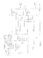
In the second DMA situation, where a transfer occurs between a CISA DMA (I/O) device and a memory, a DMA acknowledge cycle is initiated and is shown in FIG. 5 a. Host platform interface circuitry 115 gets address information from CPU 120 via bus 125, A[23:0], as well as cycle definition and command information (e.g., M/IO#, W/R#, SBHE#) from either CPU 120 or an ISA controller (not shown). In the first address phase, host platform interface circuitry 115 drives out A[23:10] on MAD[15:2]. Concurrently, host platform interface circuitry 115 drives out cycle definition information, I/D#=0 on MAD[1] and M/IO#=0 on MAD[0], as shown in FIG. 5 b. CISA DMA device and CISA memory device (both considered peripheral devices and not shown separately) then latch MAD[15:0] (address and cycle information) on the rising edge of ATCLK and decode the information.
In the second address phase, host platform interface circuitry 115 drives out remaining address information (A[9:0]), channel information (DMX[2:0]), TC (terminal count), and remaining command information (SBHE#, and W/R#), as shown in FIG. 5 b. Note that SBHE# and W/R# reference the memory device and not the I/O device, which assumes the opposite sense of W/R# for its portion of the cycle. Host platform interface circuitry 115 asserts ALE. Because the host platform interface circuitry 115 has already determined that the cycle belongs to a CISA device, the host platform interface circuitry 115 does not need to see SEL# and the CISA DMA device does not assert SEL# for the I/O portion of the cycle, but does latch the address and command information from MAD[15:0] on the rising edge of ATCLK. CISA memory device also latches address and command information, but the CISA memory device asserts SEL#. Were the CISA DMA (I/O) device to assert SEL#, contention would arise with the CISA memory device which must, in the present embodiment, respond with SEL# during the memory portion of the cycle. Host platform interface circuitry 115 then de-asserts ALE on the rising ATCLK edge.
During the data phase of the DMA acknowledge cycle, host platform interface circuitry 115 tri-states its MAD[15:0] outputs for DMA writes (i.e., I/O read, memory write), and for DMA reads (i.e., I/O write, memory read), host platform interface circuitry 115 drives write data onto MAD[15:0]. For reads and writes, host platform interface circuitry 115 asserts CMD# synchronously with the falling edge of ATCLK and must inhibit its ISA IOR#/IOW# lines. In the present embodiment, CISA DMA device may not extend a DMA acknowledge cycle with IOCHRDY, but CISA memory devices may de-assert IOCHRDY. Host platform interface circuitry 115 will de-assert CMD# synchronously with the rising edge of ATCLK.
D. Configuration Cycles.
One type of configuration cycle is a broadcast cycle, and one type of broadcast cycle is a stop clock cycle, which is shown in FIG. 6 a. A stop clock cycle indicates that the host platform interface circuitry 115 will immediately put the CISA peripheral device 130 into a low-power mode in which peripheral device 130 will no longer receive clocks. Therefore, the peripheral device 130 must enter into a state in which it can asynchronously signal that it needs the clocks restarted, for instance, if it needed to generate an interrupt to the system.
Referring to FIGS. 6 a and 6 b, the host platform interface circuitry 115 initiates the stop clock cycle by driving out command and cycle information in phase 1 of the cycle. This command and cycle information includes BRD=1 to indicate a broadcast cycle, STP#=0 to indicate a stop cycle, CC[2:0] which are clock count bits indicating how many rising clock edges the peripheral device 130 should expect after CMD# goes high before the clock is stopped, I/D#=1, and M/IO#=1. In the present embodiment, other bits on the MAD bus have been reserved. Peripheral device 130 then latches this information on the rising edge of ATCLK.
In the second phase, host platform interface circuitry drives out remaining command information, including ISA#=1 indicating fast timing (no-wait-state), SBHE#=0 to indicate 16 bits of data, and W/R#=1 because a stop clock cycle will always be a write cycle. Host platform interface circuitry 115 asserts ALE and peripheral device latches the remaining information. Peripheral device 130 does not assert SEL#, in the present embodiment.
Host platform interface circuitry asserts CMD# synchronously with the rising edge of ATCLK. Once host de-asserts CMD#, peripheral device 130 is internally in a stop-ready (STPRDY) state. After the number of clocks specified by CC[2:0], the host platform interface circuitry stops the clock, in one embodiment, in its high state. In an alternative embodiment, the host platform interface circuitry stops the clock in its low state. In FIG. 6 a, CC[2:0]=001, and the clock is brought high by host platform interface circuitry on the next rising ATCLK edge. Each additional count requires the host platform interface circuitry 115 to wait one more clock cycle before stopping the clock.
While in the STPRDY state, peripheral device 130 also counts clocks and it enters into a stop active (STPACTV) state on the specified clock edge (in FIG. 6 a, after 001 clock edges). Once in the STPACTV state, SEL#/ATB# has a third meaning: Clock Run (CLKRUN#). Peripheral device 130 can assert CLKRUN# asynchronously at any time while in the STPACTV state to signal host platform interface circuitry to restart its clock, for instance if peripheral device 130 needs to assert an interrupt request to the host.
After CLKRUN# (SEL#/ATB#) has been asserted, on the next rising edge of ATCLK, peripheral device 130 deasserts CLKRUN# but does not drive it high. Peripheral device 130 has, at this point, left the STPRDY state, but still remains in the STPACTV state and still cannot initiate or respond to any cycles. On the next falling ATCLK edge, host platform interface circuitry 115 drives SEL#/ATB# high for half an ATCLK cycle, and on the next rising ATCLK edge, host platform interface circuitry 115 stops driving SEL#/ATB#. Peripheral device 130 leaves the STPACTV state and can generate or respond to cycles. Note in FIG. 6 b that the MAD bus in the data phase of the stop clock cycle contains no useful data and is not latched.
In order to enter the second mode of operation, peripheral device 130 must sample SEL#/ATB# and CMD# high, and ALE low, on two consecutive edges of ATCLK. The peripheral device 130 will assert ATB# on a rising edge of ATCLK. At this point, in the present embodiment, the peripheral device 130 can only drive two types of information onto the bus: interrupt requests and DMA requests. Thus, rather than the three-phase multiplexing that occurred with the cycles previously discussed, this second mode of operation has two phases, an interrupt phase and a DMA request phase.
If host platform interface circuitry 115 was starting a cycle, and was about to assert ALE on the next falling edge of ATCLK, once SEL#/ATB# is asserted with ALE low, the host platform interface circuitry 115, in the present embodiment, must abort the cycle and retry it later. Even if host platform interface circuitry 115 is busy and cannot respond to the drive-back request immediately, it inhibits initiation of all other I/O and DMA operations.
As soon as AT bus operations have been completed and bus 135 is available, host platform interface circuitry 115 drives MAD[15:0] high for half an ATCLK cycle from a falling edge of ATCLK, then asserts CMD# after the next rising edge of ATCLK to acknowledge that device 130 can now drive IRQ information onto the bus. The host drives ATB# low at this time. Peripheral device 130 can now drive interrupt data onto bus 135 on the next falling edge of ATCLK, driving low only those lines with IRQ activity and not actively driving high the other lines. In this way, multiple CISA devices can drive the lines in parallel. To restore an IRQ line to its inactive state, the CISA device must initiate an IRQ driveback cycle but leave the MAD line corresponding to the inactive-going IRQ high. CISA devices must track IRQ driveback cycles initiated by other CISA devices in order to maintain an active state on any IRQ line they currently control. The IRQ generation circuitry 170, which may, in different embodiments, be external to the host platform interface circuitry 115 or built into it, uses the rising edge of ATCLK, qualified by ATB# and CMD# low, to latch IRQ information. The peripheral device 130 stops driving ATB# and the host platform interface circuitry 115 controls ATB# throughout the rest of the cycle.
As shown in FIGS. 7 a and 7 b, for DMA requests (DRQs), peripheral device 130 drives high any MAD[15:0] lines it was driving low high for one-half an ATCLK cycle, then tri-states the lines for half an ATCLK cycle. Peripheral device 130 drives DRQ information onto MAD[7:0] and, at the same time, drives low the corresponding lines MAD[15:8] to indicate which DRQ channels have a status change to be transferred. The host side DRQ generation circuitry 170, which may, in different embodiments, be external to the host platform interface circuitry 115 or built into it, samples ATB# and CMD# active on the next rising ATCLK edge after the edge on which IRQs were sampled, and latches the DRQ information on MAD[7:0] for the channel selected. The host DRQ generation circuitry may, in different embodiments, OR the DRQs obtained with other system DRQs. The host de-asserts CMD# and ATB# on the next rising edge of the ATCLK cycle.
The desired DMA request line states are latched by host platform interface circuitry 115 and will remain in that state until cleared by another DRQ drive-back cycle. This scheme allows for both DMA single transfers and DMA block transfers. The peripheral device 130 asserts SEL#/ATB# immediately any time a DRQ line changes state (assuming the current cycle is finished). The host platform interface circuitry 115, in turn, immediately de-asserts all DRQ inputs to its DRQ generation circuitry 170, including DMA requests from ISA DMA devices, until the host platform interface circuitry 115 drives a DMA acknowledge cycle. By dynamically blocking ISA device DMA requests, any need to reassign DMA channels is eliminated.
ISA Compatibility
CISA performance is comparable with that of 16-bit ISA bus peripheral devices. It does not interfere with standard ISA operations and is compatible with ISA operations. For instance, CISA ATCLK signal 165 is compatible with the standard ISA BLCK signal; CISA ALE signal 140 is compatible with the standard ISA BALE signal; and CISA IOCHRDY signal 150 is compatible with standard ISA signal IOCHRDY. In addition, in its simplest form, CMD# 145 is the AND of the IORD#, IOWR#, MRD#, and MWR# commands on the ISA bus interface. However, compatibility for the present embodiment is based upon the following assumptions:
-
- 1. No ISA peripherals can drive the MAD bus between ISA cycles. They must stay tri-stated at this time.
- 2. ATCLK can be stopped only during a stop clock broadcast configuration cycle and must run at all other times.
- 3. No standard ISA masters on the bus are allowed access to CISA peripheral devices. Standard ISA masters are simply ignored by CISA devices since these masters cannot generate CMD# and so cannot run a CISA cycle.
- 4. No bus master capability is necessary on the part of the CISA peripheral device in the present embodiment. However, the presence of SEL#/ATB# and its “backoff” feature allows bus master capabilities in other embodiments.
- 5. On receipt of an ATB# request, the CISA host must immediately inhibit all system DRQ activity until the drive-back cycle is complete. Otherwise, unwanted DMA cycles could occur.
Shared Speaker Signal
In one embodiment of the present invention, an additional digital speaker output signal (SPKROUT) is provided. Unlike conventional schemes which generally require that the digital audio outputs from each device be tied together with XOR logic, the present invention allows the digital audio outputs of any number of devices to be combined and shared, as shown in FIG. 8 . In addition SPKROUT 805 is shared among devices in the present invention without the use of open-collector outputs. Speaker data output is typically a signal driven in both the low-to-high and high-to-low directions, making an open-collector output on the speaker data output lines insufficient in that there is no guarantee that any particular speaker output line from a device will be left in a high or tri-stated condition. If one open-collector device leaves the speaker output signal low, no other open-collector device connected on the line could toggle the signal from low to high. In addition, open-collector outputs tend to consume excessive power.
Referring to FIG. 8 , SPKROUT 805 is coupled between peripheral device 830, peripheral device 831, and host platform interface circuitry 815. SPKROUT 805 is further coupled to signal receiving circuitry 890 which in turn is coupled to speaker 895. Peripheral devices 830 and 831 also receive source input A 885 and source input B 886, respectively. Source input A 885 and source input B 886 are additionally coupled to host platform interface circuitry 815. RST 860, ALE 840, and ATCLK 865 are additionally coupled between host platform interface circuitry 815 and each peripheral device 830 and 831.
In accordance with one embodiment of the invention, to share SPKROUT 805 between peripheral device 830, peripheral device 831, and host platform interface circuitry 815, the SPKROUT output of each device is first initialized and each device is synchronized. To initialize, the SPKROUT outputs of each device are tri-stated at hard reset time and remain tri-stated until individually enabled. To synchronize, referring to FIG. 9 a, on the first ALE generated by host platform interface circuitry 805, peripheral devices 830 and 831 will synchronize to ATCLK and derive the signal ATCLK/2 internally. Four distinct phases result: Phase 0 when ATCLK is high and ATCLK/2 is high; Phase 1 when ATCLK is low and ATCLK/2 is high; Phase 2 when ATCLK is high and ATCLK/2 is low; and Phase 3 when ATCLK is low and ATCLK/2 is low.
Once initialized and synchronized, a signal can be driven on the SPKROUT 805 line as shown in FIG. 9 b. On the rising ATCLK edge starting Phase 0 a peripheral device 830 wishing to drive a signal on SPKROUT 805 samples the state of SPKROUT 805. Host platform interface circuitry 815 also samples the state of SPKROUT 805. Both peripheral device 830 and host platform interface circuitry 815 maintain the speaker output of each device tri-stated during the remainder of Phase 0. On the falling edge of the ATCLK edge starting Phase 1 peripheral device 830 and host platform interface circuitry 815 each sample digital audio source input (source input A) 885. During Phase 1, if the signal on source input A 885 sampled on the falling ATCLK edge has changed since a previous phase 1 in which it was sampled, both peripheral device 830 and host platform interface circuitry 815 toggle the signal on SPKROUT 805. Toggling occurs by driving the opposite logic value (0 or 1) of the SPKROUT value sampled in Phase 0 by peripheral device 830 and host platform interface device 831.
On the rising ATCLK edge starting phase 2, both peripheral device 830 and host platform interface circuitry 815 tri-state their respective speaker outputs and maintain them tri-stated during the remainder of Phase 2. On the rising ATCLK edge starting Phase 2, host platform interface circuitry 815 additionally samples the state of SPKROUT 805. On the falling ATCLK edge starting Phase 3, host platform interface circuitry 805 drives SPKROUT to the value of SPKROUT sampled in Phase 2 by host platform interface circuitry 815. Host platform interface circuitry 815 maintains SPKROUT driven with this value for the remainder of Phase 3 while peripheral device 830 maintains its speaker output tri-stated.
Although two devices will rarely simultaneously require use of SPKROUT, should simultaneous demands occur, the scheme of the present invention eliminates contention. Both devices will sample the SPKROUT line and should a toggle be required, both would toggle the line in the same direction.
It is possible that neither peripheral device 830 nor host platform interface circuitry 815 will drive the SPKROUT 805 line for up to 1.5 ATCLK cycles. Thus, shared SPKROUT line 805 depends on an RC time constant large enough that the signal on SPKROUT 805 will not change its level any appreciable amount across a period of 1.5 ATCLKs. In one embodiment of the invention, the bus capacitance inherent on the SPKROUT line 805 will be sufficient to act as a capacitive logic level holding mechanism 891. However, in some instances, a larger capacitance may be needed to hold the logic level, the value of which will be apparent to one of ordinary skill in the art.
Further, in the present embodiment, speaker 895 is an 8 ohm speaker. Connecting speaker 895 directly to line 805 would cause the line to begin a transition when it was tri-stated. Therefore, speaker 895 should be further coupled with a high impedance input 892, which may be a simple buffer in one embodiment of the invention, or a high impedance amplifier circuit in another embodiment of the invention.
During a stop clock cycle, described above, peripheral device 830 tri-states its speaker output during the period during which both STPACTV and STPRDY are high (see FIG. 6 a). Host platform interface circuitry 815 drives SPKROUT 805 low. In another embodiment of the invention, host platform interface circuitry 815 tri-states its speaker output rather than driving SPKROUT 805 low. Even during such a stop clock cycle, however, peripheral device 830 remains synchronized to the correct phase of ATCLK and does not resynchronize on the next ALE.
Automatic Voltage Threshold Detection
CISA devices in accordance with the invention can utilize either a 5v bus or a 3.3v bus and can detect which threshold is being used automatically, without using external circuitry. To detect a 5v threshold, host platform interface circuitry 115 asserts the ALE signal to a logical high when RST also goes to a logical high. The host keeps ALE asserted for at least one-half ATCLK cycle and at most one ATCLK cycle after RST goes to a logical low. To automatically detect a 3.3v threshold, host platform interface circuitry 115 keeps the ALE signal at a logical low when RST goes to a logical high and maintains ALE at a logical low for at least one-half ATCLK cycles after RST goes to a logical low.
The invention has been described with respect to particular embodiments thereof, and it will be understood that numerous modifications are possible within the scope of the invention as set forth in the claims.
Claims (1)
1. A computer system comprising:
a host platform;
a peripheral device; and
a plurality of signal lines coupling the host platform to said peripheral device, said plurality of signal lines comprising:
an address-data bus to carry in a multiplexed manner address information for a first cycle, data information for said first cycle, at least said address information and said data information being carried on the same signal lines at different times, and cycle definition information for said first cycle, said cycle definition information being carried on the same signal lines at different times with said address information and/or said data information, said cycle definition information including a cycle type and a cycle direction, said cycle type identifying at least a memory cycle or an I/O cycle, said cycle direction identifying at least a read direction or a write direction.
Priority Applications (1)
| Application Number | Priority Date | Filing Date | Title |
|---|---|---|---|
| US11/466,222 US7523245B1 (en) | 1996-02-06 | 2006-08-22 | Compact ISA-bus interface |
Applications Claiming Priority (6)
| Application Number | Priority Date | Filing Date | Title |
|---|---|---|---|
| US08/595,989 US5944807A (en) | 1996-02-06 | 1996-02-06 | Compact ISA-bus interface |
| US09/233,230 US6098141A (en) | 1996-02-06 | 1999-01-19 | Compact ISA-bus interface |
| US58796600A | 2000-06-06 | 2000-06-06 | |
| US09/993,964 US20020059493A1 (en) | 1996-02-06 | 2001-11-14 | Compact ISA-bus interface |
| US30613702A | 2002-11-27 | 2002-11-27 | |
| US11/466,222 US7523245B1 (en) | 1996-02-06 | 2006-08-22 | Compact ISA-bus interface |
Related Parent Applications (1)
| Application Number | Title | Priority Date | Filing Date |
|---|---|---|---|
| US30613702A Continuation | 1996-02-06 | 2002-11-27 |
Publications (1)
| Publication Number | Publication Date |
|---|---|
| US7523245B1 true US7523245B1 (en) | 2009-04-21 |
Family
ID=24385555
Family Applications (4)
| Application Number | Title | Priority Date | Filing Date |
|---|---|---|---|
| US08/595,989 Expired - Lifetime US5944807A (en) | 1996-02-06 | 1996-02-06 | Compact ISA-bus interface |
| US09/233,230 Expired - Lifetime US6098141A (en) | 1996-02-06 | 1999-01-19 | Compact ISA-bus interface |
| US09/993,964 Abandoned US20020059493A1 (en) | 1996-02-06 | 2001-11-14 | Compact ISA-bus interface |
| US11/466,222 Expired - Fee Related US7523245B1 (en) | 1996-02-06 | 2006-08-22 | Compact ISA-bus interface |
Family Applications Before (3)
| Application Number | Title | Priority Date | Filing Date |
|---|---|---|---|
| US08/595,989 Expired - Lifetime US5944807A (en) | 1996-02-06 | 1996-02-06 | Compact ISA-bus interface |
| US09/233,230 Expired - Lifetime US6098141A (en) | 1996-02-06 | 1999-01-19 | Compact ISA-bus interface |
| US09/993,964 Abandoned US20020059493A1 (en) | 1996-02-06 | 2001-11-14 | Compact ISA-bus interface |
Country Status (1)
| Country | Link |
|---|---|
| US (4) | US5944807A (en) |
Cited By (4)
| Publication number | Priority date | Publication date | Assignee | Title |
|---|---|---|---|---|
| US20080313479A1 (en) * | 2005-06-10 | 2008-12-18 | Freescale Semiconductor, Inc. | Device and Method for Media Access Control |
| US20090175393A1 (en) * | 2005-06-10 | 2009-07-09 | Sanit-Gobain Glass France | Method and device for frame synchronization |
| CN102238053A (en) * | 2010-05-06 | 2011-11-09 | 上海固泰科技有限公司 | Controller area network (CAN) bus interference generator |
| CN111506168A (en) * | 2020-03-31 | 2020-08-07 | 苏州浪潮智能科技有限公司 | Server system and anti-interference method and device thereof |
Families Citing this family (10)
| Publication number | Priority date | Publication date | Assignee | Title |
|---|---|---|---|---|
| US5944807A (en) | 1996-02-06 | 1999-08-31 | Opti Inc. | Compact ISA-bus interface |
| US6151654A (en) * | 1997-12-24 | 2000-11-21 | Intel Corporation | Method and apparatus for encoded DMA acknowledges |
| US6209051B1 (en) * | 1998-05-14 | 2001-03-27 | Motorola, Inc. | Method for switching between multiple system hosts |
| US6321174B1 (en) * | 1999-02-09 | 2001-11-20 | Winbond Electronics Corp. | Apparatus and method for testing add-on device of a computer system |
| US6725305B1 (en) * | 1999-12-29 | 2004-04-20 | Agere Systems Inc. | Method and apparatus for using a bus as a data storage node |
| US7315551B2 (en) * | 2002-03-15 | 2008-01-01 | Lockheed Martin Corporation | Synchronous low voltage differential I/O buss |
| US7073007B1 (en) * | 2003-07-22 | 2006-07-04 | Cisco Technology, Inc. | Interrupt efficiency across expansion busses |
| CN101510182B (en) * | 2009-04-03 | 2012-09-05 | 无锡中星微电子有限公司 | Low speed DMA interface chip system and internal memory access method |
| US9756568B2 (en) * | 2015-09-24 | 2017-09-05 | Mediatek Inc. | Enhance AT command for backoff timer control |
| US10034325B2 (en) | 2015-09-24 | 2018-07-24 | Mediatek Inc. | Enhance at command for backoff timer control |
Citations (24)
| Publication number | Priority date | Publication date | Assignee | Title |
|---|---|---|---|---|
| US4315308A (en) | 1978-12-21 | 1982-02-09 | Intel Corporation | Interface between a microprocessor chip and peripheral subsystems |
| US4315310A (en) | 1979-09-28 | 1982-02-09 | Intel Corporation | Input/output data processing system |
| US4325120A (en) | 1978-12-21 | 1982-04-13 | Intel Corporation | Data processing system |
| US4367524A (en) | 1980-02-07 | 1983-01-04 | Intel Corporation | Microinstruction execution unit for use in a microprocessor |
| US4402046A (en) | 1978-12-21 | 1983-08-30 | Intel Corporation | Interprocessor communication system |
| US4480307A (en) | 1982-01-04 | 1984-10-30 | Intel Corporation | Interface for use between a memory and components of a module switching apparatus |
| US4503535A (en) | 1982-06-30 | 1985-03-05 | Intel Corporation | Apparatus for recovery from failures in a multiprocessing system |
| US4750177A (en) * | 1981-10-01 | 1988-06-07 | Stratus Computer, Inc. | Digital data processor apparatus with pipelined fault tolerant bus protocol |
| US4935868A (en) * | 1988-11-28 | 1990-06-19 | Ncr Corporation | Multiple port bus interface controller with slave bus |
| WO1990010267A1 (en) | 1989-02-24 | 1990-09-07 | Nexgen Microsystems | Distributed pipeline control for a computer |
| US5175820A (en) * | 1990-08-31 | 1992-12-29 | Advanced Micro Devices, Inc. | Apparatus for use with a computing device controlling communications with a plurality of peripheral devices including a feedback bus to indicate operational modes |
| US5218684A (en) * | 1987-09-04 | 1993-06-08 | Digital Equipment Corporation | Memory configuration system |
| US5243703A (en) | 1990-04-18 | 1993-09-07 | Rambus, Inc. | Apparatus for synchronously generating clock signals in a data processing system |
| US5319755A (en) | 1990-04-18 | 1994-06-07 | Rambus, Inc. | Integrated circuit I/O using high performance bus interface |
| US5369748A (en) | 1991-08-23 | 1994-11-29 | Nexgen Microsystems | Bus arbitration in a dual-bus architecture where one bus has relatively high latency |
| US5448742A (en) | 1992-05-18 | 1995-09-05 | Opti, Inc. | Method and apparatus for local memory and system bus refreshing with single-port memory controller and rotating arbitration priority |
| US5517624A (en) | 1992-10-02 | 1996-05-14 | Compaq Computer Corporation | Multiplexed communication protocol between central and distributed peripherals in multiprocessor computer systems |
| US5531327A (en) | 1994-11-02 | 1996-07-02 | T.H.E.M. Industries, Inc. | Pallet system including end panels |
| US5710906A (en) | 1995-07-07 | 1998-01-20 | Opti Inc. | Predictive snooping of cache memory for master-initiated accesses |
| US5740385A (en) | 1994-12-19 | 1998-04-14 | Intel Corporation | Low load host/PCI bus bridge |
| US5793990A (en) | 1993-06-11 | 1998-08-11 | Vlsi Technology, Inc. | Multiplex address/data bus with multiplex system controller and method therefor |
| US5857117A (en) | 1995-12-22 | 1999-01-05 | Intel Corporation | Apparatus and method for multiplexing integrated device electronics circuitry with an industry standard architecture bus |
| US5924119A (en) | 1990-11-30 | 1999-07-13 | Xerox Corporation | Consistent packet switched memory bus for shared memory multiprocessors |
| US5944807A (en) | 1996-02-06 | 1999-08-31 | Opti Inc. | Compact ISA-bus interface |
Family Cites Families (16)
| Publication number | Priority date | Publication date | Assignee | Title |
|---|---|---|---|---|
| US5125080A (en) * | 1989-11-13 | 1992-06-23 | Chips And Technologies, Incorporated | Logic support chip for AT-type computer with improved bus architecture |
| US5109517A (en) * | 1990-10-09 | 1992-04-28 | Ast Research, Inc. | System for selectively controlling slots in an IBM-AT/NEC 9801 dual-compatible computer |
| US5467295A (en) * | 1992-04-30 | 1995-11-14 | Intel Corporation | Bus arbitration with master unit controlling bus and locking a slave unit that can relinquish bus for other masters while maintaining lock on slave unit |
| DE69331061T2 (en) * | 1992-08-10 | 2002-06-06 | Monolithic System Tech Inc | Fault-tolerant hierarchical bus system |
| US5379403A (en) * | 1992-11-27 | 1995-01-03 | Ncr Corporation | Method and interface adapter for interfacing an ISA board to an MCA system by the issuance of an ILLINI-CDCHRDY signal from the interface adapter |
| US5511224A (en) * | 1993-02-18 | 1996-04-23 | Unisys Corporation | Configurable network using dual system busses with common protocol compatible for store-through and non-store-through cache memories |
| US5586294A (en) * | 1993-03-26 | 1996-12-17 | Digital Equipment Corporation | Method for increased performance from a memory stream buffer by eliminating read-modify-write streams from history buffer |
| US5574866A (en) * | 1993-04-05 | 1996-11-12 | Zenith Data Systems Corporation | Method and apparatus for providing a data write signal with a programmable duration |
| US5748982A (en) * | 1993-04-05 | 1998-05-05 | Packard Bell Nec | Apparatus for selecting a user programmable address for an I/O device |
| US5794070A (en) * | 1993-06-30 | 1998-08-11 | Intel Corporation | Method and apparatus for fast DMA transfer on an industry standard architecture (ISA) bus |
| US5613075A (en) * | 1993-11-12 | 1997-03-18 | Intel Corporation | Method and apparatus for providing deterministic read access to main memory in a computer system |
| US5632020A (en) * | 1994-03-25 | 1997-05-20 | Advanced Micro Devices, Inc. | System for docking a portable computer to a host computer without suspending processor operation by a docking agent driving the bus inactive during docking |
| US5617559A (en) * | 1994-08-31 | 1997-04-01 | Motorola Inc. | Modular chip select control circuit and method for performing pipelined memory accesses |
| US5564114A (en) * | 1995-01-09 | 1996-10-08 | Cirrus Logic Inc. | Method and an arrangement for handshaking on a bus to transfer information between devices in a computer system |
| US5651137A (en) * | 1995-04-12 | 1997-07-22 | Intel Corporation | Scalable cache attributes for an input/output bus |
| US5649125A (en) * | 1995-10-30 | 1997-07-15 | Motorola, Inc. | Method and apparatus for address extension across a multiplexed communication bus |
-
1996
- 1996-02-06 US US08/595,989 patent/US5944807A/en not_active Expired - Lifetime
-
1999
- 1999-01-19 US US09/233,230 patent/US6098141A/en not_active Expired - Lifetime
-
2001
- 2001-11-14 US US09/993,964 patent/US20020059493A1/en not_active Abandoned
-
2006
- 2006-08-22 US US11/466,222 patent/US7523245B1/en not_active Expired - Fee Related
Patent Citations (28)
| Publication number | Priority date | Publication date | Assignee | Title |
|---|---|---|---|---|
| US4325120A (en) | 1978-12-21 | 1982-04-13 | Intel Corporation | Data processing system |
| US4402046A (en) | 1978-12-21 | 1983-08-30 | Intel Corporation | Interprocessor communication system |
| US4315308A (en) | 1978-12-21 | 1982-02-09 | Intel Corporation | Interface between a microprocessor chip and peripheral subsystems |
| US4315310A (en) | 1979-09-28 | 1982-02-09 | Intel Corporation | Input/output data processing system |
| US4367524A (en) | 1980-02-07 | 1983-01-04 | Intel Corporation | Microinstruction execution unit for use in a microprocessor |
| US4750177A (en) * | 1981-10-01 | 1988-06-07 | Stratus Computer, Inc. | Digital data processor apparatus with pipelined fault tolerant bus protocol |
| US4480307A (en) | 1982-01-04 | 1984-10-30 | Intel Corporation | Interface for use between a memory and components of a module switching apparatus |
| US4503535A (en) | 1982-06-30 | 1985-03-05 | Intel Corporation | Apparatus for recovery from failures in a multiprocessing system |
| US5218684A (en) * | 1987-09-04 | 1993-06-08 | Digital Equipment Corporation | Memory configuration system |
| US4935868A (en) * | 1988-11-28 | 1990-06-19 | Ncr Corporation | Multiple port bus interface controller with slave bus |
| WO1990010267A1 (en) | 1989-02-24 | 1990-09-07 | Nexgen Microsystems | Distributed pipeline control for a computer |
| US5243703A (en) | 1990-04-18 | 1993-09-07 | Rambus, Inc. | Apparatus for synchronously generating clock signals in a data processing system |
| US5319755A (en) | 1990-04-18 | 1994-06-07 | Rambus, Inc. | Integrated circuit I/O using high performance bus interface |
| US5638334A (en) | 1990-04-18 | 1997-06-10 | Rambus Inc. | Integrated circuit I/O using a high performance bus interface |
| US5841715A (en) | 1990-04-18 | 1998-11-24 | Rambus, Inc. | Integrated circuit I/O using high performance bus interface |
| US5175820A (en) * | 1990-08-31 | 1992-12-29 | Advanced Micro Devices, Inc. | Apparatus for use with a computing device controlling communications with a plurality of peripheral devices including a feedback bus to indicate operational modes |
| US5924119A (en) | 1990-11-30 | 1999-07-13 | Xerox Corporation | Consistent packet switched memory bus for shared memory multiprocessors |
| US5369748A (en) | 1991-08-23 | 1994-11-29 | Nexgen Microsystems | Bus arbitration in a dual-bus architecture where one bus has relatively high latency |
| US5448742A (en) | 1992-05-18 | 1995-09-05 | Opti, Inc. | Method and apparatus for local memory and system bus refreshing with single-port memory controller and rotating arbitration priority |
| US5517624A (en) | 1992-10-02 | 1996-05-14 | Compaq Computer Corporation | Multiplexed communication protocol between central and distributed peripherals in multiprocessor computer systems |
| US5793990A (en) | 1993-06-11 | 1998-08-11 | Vlsi Technology, Inc. | Multiplex address/data bus with multiplex system controller and method therefor |
| US5531327A (en) | 1994-11-02 | 1996-07-02 | T.H.E.M. Industries, Inc. | Pallet system including end panels |
| US5740385A (en) | 1994-12-19 | 1998-04-14 | Intel Corporation | Low load host/PCI bus bridge |
| US5710906A (en) | 1995-07-07 | 1998-01-20 | Opti Inc. | Predictive snooping of cache memory for master-initiated accesses |
| US5813036A (en) | 1995-07-07 | 1998-09-22 | Opti Inc. | Predictive snooping of cache memory for master-initiated accesses |
| US5857117A (en) | 1995-12-22 | 1999-01-05 | Intel Corporation | Apparatus and method for multiplexing integrated device electronics circuitry with an industry standard architecture bus |
| US5944807A (en) | 1996-02-06 | 1999-08-31 | Opti Inc. | Compact ISA-bus interface |
| US6098141A (en) * | 1996-02-06 | 2000-08-01 | Opti Inc. | Compact ISA-bus interface |
Non-Patent Citations (25)
| Title |
|---|
| "Embedded Intel486 Processor Hardware Reference Manual," Intel Corporation, Jul. 1997, 334 pages. |
| "PCI Local Bus Specification" Rev. 2.0 (Hillsboro, Oregon, PCI Special Interest Group 1993) 210 pages. |
| Draft ANSI Standard X3T10, 791D, Rev. 4C, Information Technology, AT Attachment Interface for Disk Drives, 1994, 76 pages. |
| IEEE Standard 1212.1-1993(2001), IEEE Standard for Communicating Among Processors and Peripherals Using Shared Memory (Direct Memory Access-DMA), 1994, 134 pages. |
| IEEE Standard 1212-1991, IEEE Standard Control and Status Register (CSR) Architecture for Microcomputer Buses, Jul. 28, 1992, 133 pages. |
| IEEE Standard 1596.5-1993, IEEE Standard for Shared-Data Formats Optimized for Scalable Coherent Interface (SCI) Processors, Jun. 17, 1993, 80 pages. |
| IEEE Standard 1596-1992, IEEE Standard for Scalable Coherent Interface (SCI), 1992, 255 pages. |
| IEEE Standard Digital Interface for Programmable Instrumentation (Std 488.2-1987) Jun. 11, 1987, 207 pages. |
| IEEE Standard Microcomputer System Bus (Std 796-1983), Dec. 9, 1982, 50 pages. |
| IEEE Standard Specifications for an I/O Expansion Bus: SBX Bus (Std 959-1988), Jun. 9, 1988, 41 pages. |
| Intel, "8237A High Performance Programmable DMA Controller (8237A-5)." Datasheet Sep. 1993, 19 pages. |
| Intel, 8008 8-Bit Parallel Central Processing Unit, MCS-8 Micro Computer Set, Rev. 1, Jun. 1972, 59 pages. |
| Intel, Intel Low Pin Count (LPC) Interface Specification, Rev. 1.1, Aug. 2002, 54 pages. |
| Intel, Low Pin Count (LPC) Interface Specification, Rev. 1.0, Sep. 29, 1997, 39 pages. |
| Intel, MCS-4, Micro Computer Set, 1972, 12 pages. |
| Intel, MCS-4, Micro Computer Set, Users Manual, Rev. 2, Mar. 1972, 125 pages. |
| Intel, MCS-4, Micro Computer Set, Users Manual, Rev. 3, Jul. 1972, 120 pages. |
| ISA Bus Technical Summary, Techfest, Dec. 9, 2002, can be found at http://www.techfest.com/hardware/bus/isa.htm, 11 pages. |
| OPTI 82C465MV/MVA/MVB, Single-Chip Mixed Voltage Notebook Solution, Data Book, Rev. 3, Oct. 1997, 284 pages. |
| OPTi, "FireStar Plus, 64-Bit CPU Single Chip Notebook Solution, Addendum to Preliminary Data Book" Rev. 1.0, Oct. 3, 1997, 158 pages. |
| OPTi, "FireStar/FireStar ACPI, 64-Bit CPU Single Chip Notebook Solution, Preliminary Data Book," Rev. 1.0, Feb. 28, 1997, 424 pages. |
| Opti-386/486WB EISA Chipset 82C681/82C682/82C686/82C687 (EBC/MCC/ISP/DBC Databook Preliminary, v 1.3 1992, 130 pages. |
| PC Card Standard Rev. 2.0, PCMCIA (Sunnyvale, CA 1991), 172 pages. |
| Solari "At Bus Design" (San Diego, Annabooks, 1990), 106 pages. |
| Solari, Edward, Theory and Operation, Including PC, XT, AT, ISA and EISA I/O Bus Operation, Annabooks, San Diego, CA Copyright 1992, 77 pages. |
Cited By (6)
| Publication number | Priority date | Publication date | Assignee | Title |
|---|---|---|---|---|
| US20080313479A1 (en) * | 2005-06-10 | 2008-12-18 | Freescale Semiconductor, Inc. | Device and Method for Media Access Control |
| US20090175393A1 (en) * | 2005-06-10 | 2009-07-09 | Sanit-Gobain Glass France | Method and device for frame synchronization |
| US8223910B2 (en) | 2005-06-10 | 2012-07-17 | Freescale Semiconductor, Inc. | Method and device for frame synchronization |
| US9047415B2 (en) * | 2005-06-10 | 2015-06-02 | Freescale Semiconductor, Inc. | Device and method for media access control |
| CN102238053A (en) * | 2010-05-06 | 2011-11-09 | 上海固泰科技有限公司 | Controller area network (CAN) bus interference generator |
| CN111506168A (en) * | 2020-03-31 | 2020-08-07 | 苏州浪潮智能科技有限公司 | Server system and anti-interference method and device thereof |
Also Published As
| Publication number | Publication date |
|---|---|
| US5944807A (en) | 1999-08-31 |
| US6098141A (en) | 2000-08-01 |
| US20020059493A1 (en) | 2002-05-16 |
Similar Documents
| Publication | Publication Date | Title |
|---|---|---|
| US7523245B1 (en) | Compact ISA-bus interface | |
| US6226700B1 (en) | Computer system with bridge logic that includes an internal modular expansion bus and a common master interface for internal master devices | |
| US5802324A (en) | Computer system with PCI repeater between primary bus and second bus | |
| US5838932A (en) | Transparent PCI to PCI bridge with dynamic memory and I/O map programming | |
| US6088517A (en) | Interfacing direct memory access devices to a non-ISA bus | |
| US5392407A (en) | Multi-port processor with peripheral component interconnect port and rambus port | |
| US5815734A (en) | System and method for reconfiguring configuration registers of a PCI bus device in response to a change in clock signal frequency | |
| US6119189A (en) | Bus master transactions on a low pin count bus | |
| US6131127A (en) | I/O transactions on a low pin count bus | |
| US5220651A (en) | Cpu-bus controller for accomplishing transfer operations between a controller and devices coupled to an input/output bus | |
| US5826048A (en) | PCI bus with reduced number of signals | |
| US5309568A (en) | Local bus design | |
| KR20010071327A (en) | System bus with serially connected pci interfaces | |
| US5507002A (en) | Peripheral component interconnect special cycle protocol using soft message IDS | |
| US6101566A (en) | Computer system with bridge logic that includes an internal modular expansion bus and a common target interface for internal target devices | |
| US5502824A (en) | Peripheral component interconnect "always on" protocol | |
| US5774681A (en) | Method and apparatus for controlling a response timing of a target ready signal on a PCI bridge | |
| JPH11120120A (en) | Interface circuit for card bus and pc card for card bus having it | |
| KR20010024260A (en) | Direct memory access(dma) transactions on a low pin count bus | |
| US5838995A (en) | System and method for high frequency operation of I/O bus | |
| US5918026A (en) | PCI to PCI bridge for transparently completing transactions between agents on opposite sides of the bridge | |
| US6047349A (en) | System for communicating through a computer system bus bridge | |
| US5978878A (en) | Selective latency reduction in bridge circuit between two busses | |
| US5559968A (en) | Non-conforming PCI bus master timing compensation circuit | |
| EP0476872B1 (en) | Work station including interfacing means for transferring data between first and second buses |
Legal Events
| Date | Code | Title | Description |
|---|---|---|---|
| FPAY | Fee payment |
Year of fee payment: 4 |
|
| REMI | Maintenance fee reminder mailed | ||
| LAPS | Lapse for failure to pay maintenance fees | ||
| STCH | Information on status: patent discontinuation |
Free format text: PATENT EXPIRED DUE TO NONPAYMENT OF MAINTENANCE FEES UNDER 37 CFR 1.362 |
|
| FP | Lapsed due to failure to pay maintenance fee |
Effective date: 20170421 |