US7526384B2 - Method for correcting a 3D location measured by a tracking system assuming a vertical offset - Google Patents
Method for correcting a 3D location measured by a tracking system assuming a vertical offset Download PDFInfo
- Publication number
- US7526384B2 US7526384B2 US11/371,222 US37122206A US7526384B2 US 7526384 B2 US7526384 B2 US 7526384B2 US 37122206 A US37122206 A US 37122206A US 7526384 B2 US7526384 B2 US 7526384B2
- Authority
- US
- United States
- Prior art keywords
- data
- survey tool
- survey
- region
- position data
- Prior art date
- Legal status (The legal status is an assumption and is not a legal conclusion. Google has not performed a legal analysis and makes no representation as to the accuracy of the status listed.)
- Expired - Fee Related
Links
Images


Classifications
-
- G—PHYSICS
- G01—MEASURING; TESTING
- G01V—GEOPHYSICS; GRAVITATIONAL MEASUREMENTS; DETECTING MASSES OR OBJECTS; TAGS
- G01V11/00—Prospecting or detecting by methods combining techniques covered by two or more of main groups G01V1/00 - G01V9/00
-
- G—PHYSICS
- G01—MEASURING; TESTING
- G01C—MEASURING DISTANCES, LEVELS OR BEARINGS; SURVEYING; NAVIGATION; GYROSCOPIC INSTRUMENTS; PHOTOGRAMMETRY OR VIDEOGRAMMETRY
- G01C15/00—Surveying instruments or accessories not provided for in groups G01C1/00 - G01C13/00
-
- G—PHYSICS
- G01—MEASURING; TESTING
- G01V—GEOPHYSICS; GRAVITATIONAL MEASUREMENTS; DETECTING MASSES OR OBJECTS; TAGS
- G01V3/00—Electric or magnetic prospecting or detecting; Measuring magnetic field characteristics of the earth, e.g. declination, deviation
- G01V3/38—Processing data, e.g. for analysis, for interpretation, for correction
Definitions
- the present subject matter relates to techniques and equipment to correct location of a survey tool, such as a ground penetrating radar unit, for tilt or offset from a vertical orientation of the tool.
- a survey tool such as a ground penetrating radar unit
- a current system for tracking position of a survey instrument or tool such as the Spectra Precision® Optical TS415 Total Station from Trimble, consists of a fixed ground station and a reflector, which is usually mounted onto a pole. The pole creates a vertical offset from the surface of the region being surveyed.
- a leveled self-tracking laser theodolite on the ground station sends out a laser that hits the reflector and is bounced back to the ground station.
- a data processor of the tracking system calculates the x, y, z, and position of the reflector by measuring the time of flight for the bounced laser and the two angles between the ground station and the reflector. The data processor compensates for any vertical offset between the reflector and the target.
- the data processor does not correct for angular offsets.
- the surveying pole must be held completely vertical over the target.
- Most surveying poles are equipped with a “bulls-eye” level to aid in holding the pole completely vertical. This technique is adequate for survey applications that can utilize the vertical pole and reflector, for measurements of relatively fixed positions.
- One such application would be tracking a moving vehicle with an attached sensor platform (survey tool) that has a rigidly attached survey pole, as the vehicle moves over an irregular surface. Often, ground or street surfaces, for example, have non-zero angles with respect to the horizontal (that is to say non-zero inclination). As the vehicle moves over such a surface, the pole remains perpendicular relative to the vehicle, typically with respect to the surface; but it will not always be vertical. In such an application, the tracking system would record erroneous position data whenever the vehicle encountered a non-horizontal surface.
- a GPS receiver could be employed to track a survey tool. And similarly, if the GPS receiver is mounted on a pole or housing that is rigidly affixed to the survey tool with some vertical offset from the surface, the GPS receiver would record erroneous position data whenever the vehicle encountered a non-horizontal surface.
- a method to try and compensate for the non-horizontal surface effects would be to gimble-mount the survey pole (or GPS antenna). However, this still would not solve the problem. Although gimble mounting would keep the survey pole (or GPS antenna) vertical, the position of the bottom of the pole would always be changing relative to the survey tool as the contour of the ground or other surface varied.
- a method is described for tilt correction of a three-dimensional (3D) location measured by a tracking system associated with a survey tool.
- Systems and data processing equipment/programs which utilize aspects of the correction technique, are also disclosed.
- an inertial measurement unit or “IMU” which measures pitch and roll angles and optionally yaw angle
- a dual axis inclinometer or two single axis inclinometers are used to measure the amount a survey tool is tilted.
- a tracking station is used to track the survey tool; and a pole with a reflector is attached to the survey tool.
- the tracking station records the 3D position of the survey tool, albeit with angular offset errors.
- a GPS receiver could be used to track the system, although the data will incorporate errors due to angular offsets as the tool moves or is re-positioned and provides measurement data and corresponding position data.
- the IMU or tilt sensor(s) measure the angular offsets.
- the tilt (orientation) data is used to correct position data to compensate for the angular offsets and thereby reduce or eliminate the errors.
- Data from the tracking station (or GPS) is merged with tilt data after surveying is completed and post processed either on the local computer or transferred to a desktop computer for later position correction processing.
- the tilt data and position data could be merged in real-time (as data is collected), and the position correction could occur in hardware using an embedded system, or on a local computer using wireless data transfer. Subsequent processing of the measurement data can then use the corrected position data, e.g. for merging with the measurement data to produce more accurate images of sub-surface features or objects.
- a method of processing position data from a survey involves obtaining position data corresponding to a point on a surface of a region to be surveyed, at which a survey tool is positioned; and obtaining angular offset data.
- the offset data represents offset of the survey tool from a normal orientation, e.g. vertical, at the point on the surface of the region.
- the method then entails correcting the corresponding position data, based on the angular offset data.
- the tool may be a simple pole, contact probe or the like, in which case the corrected position data itself is the desired survey data.
- applications discussed below also involve physical measurements of properties of the surveyed region taken at different points on the surface of the region.
- a method of generating measurement data and position data from a survey of a region may involve obtaining measurement data representing a measured physical property of the region from a survey tool, when the survey tool is positioned at various points on a surface of the region.
- Survey tool position data corresponding to each of the points on the surface of the region, also is obtained.
- Angular offset data representing offset of orientation of the survey tool from a normal orientation at the points on the surface of the region, caused by variations in inclination of the surface, enables correction of the corresponding position data.
- a computer or the like processes the measurement data based on the corrected corresponding position data.
- This processing may generate images of features or objects below the surface, e.g. of subterranean features or objects buried under a portion of a road or the ground.
- the angular offset data represents variations in orientation of the survey tool due to variations of the surface with respect to horizontal.
- position data corresponding to each of the points corresponds to a position offset from the surface, e.g. due to an offset of a position detection element from the surface.
- the angular offset data represents an angle of an axis of this position offset, relative to a vertical orientation over the surveyed region. Examples are disclosed that measure the angular offset data with respect to two or more axes of the survey tool.
- the survey tool could be a relatively static device moved manually from point to point
- the examples of the tool utilize a moveable platform, so that the survey tool can traverse the surface of the region.
- the various types of data are obtained at least periodically, e.g. at regular intervals or continuously, as the survey tool traverses the surface of the region.
- Such a system might include a survey tool and a position detection device that is responsive to position of the survey tool.
- An inclinometer coupled to the survey tool, provides angular offset data in response to orientation of the survey tool, representing offset of the survey tool from a normal orientation.
- a data processor corrects the position data, based on the angular offset data.
- the survey system may simply provide position data regarding one or more points on the surface.
- the tool is a mechanism for locating an element of the position detection device at a desired point, such as a survey pole or contact probe.
- a desired point such as a survey pole or contact probe.
- many applications will also involve associated sensors for measurements of a property of a region to be surveyed, such as a sub-surface characteristic as might be measured and processed to detect buried objects or subterranean features.
- the survey tool comprises a movable platform and one or more sensors mounted on the moveable platform for detecting the physical property of the region platform moves over the surface.
- the position detection device includes an element, e.g. a reflector or a GPS receiver, mounted on the platform at a location on the platform that will be offset from the surface of the region when the survey tool performs measurements.
- the angular offset data represents an angle of an axis of the offset of the element of the position detection device, relative to a vertical orientation over the region.
- the system may use a variety of sensing technologies.
- Disclosed examples include a ground penetrating radar (GPR) array, an array of electromagnetic induction antennas, an array of magnetometers, an array of vibrometers and an array of optical sensors.
- GPR ground penetrating radar
- the inclinometer include an inertial measurement unit (IMU), a dual axis inclinometer and two single axis inclinometers.
- IMU inertial measurement unit
- the position detection device include a self-tracking laser theodolite ground station with a reflector attached to the survey tool for reflecting a laser beam from the ground station back to the ground station; and a GPS receiver attached to the survey tool.
- a data processing system might include at least one programmable processor and programming executable by the at least one processor. Execution of the programming causes the processor(s) to implement functions.
- the functions include receiving measurement data representing a measured physical property of a region, when a survey tool is positioned at various points on a surface of the region; and receiving survey tool position data corresponding to each of the points on the surface of the region.
- the functions also include receiving angular offset data, representing offset of orientation of the survey tool from a normal orientation, at each of the points on the surface of the region.
- the processor can correct the corresponding position data, based on the angular offset data.
- FIGS. 1A to 1C provide high-level functional illustrations of a survey tool system, with tool position detection and correction for vertical offset or tilt angle of the tool.
- FIG. 2 is a flow chart illustrating a high-level view data collection and processing operation.
- FIG. 3 is a flow chart illustrating the procedure used to correct for angular offset.
- FIG. 4 is a 2D (XY plane view) depicting the results for tilt correction performed on experimental data in the lab.
- FIG. 5 is a 2D plot (XZ plane view) depicting the results for tilt correction performed on experimental data in the lab.
- FIG. 6 is a 3D plot depicting the results for tilt correction performed on experimental data in the lab.
- FIG. 7 is a table showing the results for tilt correction performed on experimental data in the lab.
- FIG. 8 depicts the experimental setup for a laboratory test.
- FIG. 9 is a 2D (XY plane view) plot depicting the results for tilt correction performed on data from field experiments using a mock survey tool setup.
- FIG. 10 is a 2D (XZ plane view) plot depicting the results for tilt correction performed on data from field experiments using a mock survey tool setup.
- FIG. 11 is 3D plot depicting the results plot depicting the results for tilt correction performed on data from field experiments using a mock survey tool setup.
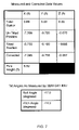
- FIG. 12 is a table showing the measured tilt angles and recorded parameters for tilt correction performed on data from field experiments using a mock survey tool setup.
- FIG. 13 depicts the experimental setup for the field test using a mock survey tool.
- FIG. 14 illustrates the expected deviation in elevation measurements for various tilt angles for a 7 ft prism pole.
- FIG. 15 illustrates the expected deviation in inline position measurements for various pitch tilt angles for a 7 ft prism pole.
- FIG. 16 illustrates the expected deviation in lateral position measurements for various roll and pitch tilt angles for a 7 ft prism pole.
- FIG. 17 illustrates the expected deviation in inline position measurements for various pitch tilt angle and varying prism pole heights.
- the various methods and systems disclosed herein relate to correcting position data regarding a moveable survey tool, to allow for tilt or offset of the tool from a normal orientation (e.g. from the vertical), for example, as may be caused by the angle of the ground over which the survey tool moves.
- the position data correction techniques disclosed herein may be used with various implementations of survey tools.
- a survey tool could be composed of any of the following examples but is not limited to:
- any sensor mounted on a moving platform any sensor mounted on a moving platform.
- FIGS. 1A and 1B illustrate an example of the system, showing top and side views of the functional elements in operation.
- FIG. 1C is an isometric view of the survey tool showing a number of relevant angles and the like.
- the tilt correction may be applied to a variety of survey tools that traverse surfaces that may or may not be horizontal.
- a survey tool 101 that consists of an array of Ground Penetrating Radar (GPR) Transmitter(s) and Receiver(s) 102 that is towed by a vehicle 103 .
- the GPR transmitter produces a pulse of electromagnetic radiation that is transmitted into a region of the ground over which the tool 101 is positioned or moving.
- the antennas receive the back-scattered electromagnetic radiation from the pulse.
- GPR Ground Penetrating Radar
- the system includes one or more elements for determining the position of the survey tool 101 , at the various points or positions of the tool 101 on or above the surface of the ground that the system is surveying.
- the system might use a GPS receiver.
- the system uses a self-tracking laser theodolite and an associated pole mounted reflector or prism.
- a Spectra Precision® Optical TS415 Total Station 104 from Trimble is used to track and record the 3D position of the survey tool.
- a tracking prism 105 is mounted on a pole 115 that is rigidly affixed to the survey tool 101 . When the survey tool 101 is on a horizontal surface, the pole 115 is vertical.
- ground or street surfaces often are horizontal, such surfaces often have non-zero angles with respect to the horizontal (that is to say non-zero inclination).
- the normal orientation of the tool would be vertical, so that the offset from the surface to the element of the position detecting device (e.g. tracking prism 105 or other reflector or a GPS receiver) on the tool 101 would be a vertical offset perpendicular to the surface the tool traverses.
- the position detecting device e.g. tracking prism 105 or other reflector or a GPS receiver
- one or more inclinometers are provided for detecting angular offset from the normal vertical orientation, of a system axis that is perpendicular to the surface the tool traverses and thus of the position offset.
- a Microstrain 3DM-GX1 IMU 106 is mounted to the surface of the GPR and is used to measure the pitch, roll, and yaw angles of the system.
- the IMU 106 is best mounted so that one axis is aligned to the direction of motion of the survey tool 113 . This in turn defines the local coordinate system for the IMU 114 at any given point along the survey path 111 .
- the orientation of the IMU axis does not need to be mounted with one axis in the direction of motion. The only requirement is to have the IMU/tilt sensor(s) rigidly mounted in a known orientation that is in the same plane as the surface of the survey tool for which tilt measurements are to be made.
- a survey wheel 107 attached to the survey tool 101 triggers data collection at a predetermined spacing interval.
- Orientation data i.e. angular offset
- ground penetrating radar data are saved onto a local laptop computer 108 (or other data storage media).
- the data is transferred to the laptop computer either through cabling or wireless data communications.
- position data from the Total Station 104 and orientation data from the IMU 106 are transferred to the same computer.
- This computer may be the laptop 108 used during the data collection or it may be a desktop computer or host computer (not shown) at another location. At this point, processing of the data can occur.
- the programmable data processing device that processes the position data and possibly the ground penetrating radar data may be essentially any type of general purpose computer.
- a device includes one or more central processing units (CPUs) for processing data in accord with program instructions.
- CPUs central processing units
- the device also typically includes a number of different types of memories and mass storage devices, for storing data and instructions.
- the computer system will provide a direct user interface, e.g. as would the laptop used for data collection, it may also include or connect to any convenient display or printer as well as input devices such as a touchpad, keyboard, mouse, trackball or the like.
- the components contained in the computer system(s) are those typically found in general purpose computer systems used as servers, workstations, personal computers network terminals, and the like. In fact, these components are intended to represent a broad category of such computer components that are well known in the art that may be used for either or both of the data collection function and the data processing function discussed herein.
- FIG. 2 is a flow chart illustrating a generic high-level view of data collection and processing.
- Survey tool data is collected in step 200 .
- Uncorrected position data is collected in step 201 .
- Orientation data is collected in step 202 .
- the tilt data and position data are merged in step 203 and processed.
- Corrected position data is produced in step 204 .
- step 205 data processing of survey tool data with corrected position data is performed, e.g. to produce maps or images of sub-surface objects from the ground penetrating radar data.
- Data processing is currently implemented using Matlab 7.0 programming code. However, many other suitable computer programming languages could be used such as C, C++, FORTRAN, Mathematica and Visual Basic, for example.
- step 300 tilt angle measurements are matched with the corresponding geodetic survey point.
- h p 815 is the height of the survey pole 115 theta ( ⁇ ) 115 is the pitch angle and psi ( ⁇ ) 116 is the roll angle of the survey tool 101 as recorded by the 3DM-GX1 IMU 106 in the IMU's local (x′,y,z′) coordinate system 114 .
- step 306 the unit direction vectors, ⁇ right arrow over (u) ⁇ i , and unit direction vectors ⁇ right arrow over (n) ⁇ i (a unit direction vector perpendicular to ⁇ right arrow over (u) ⁇ i ), are calculated using the following equations
- direction vectors could be calculated from the “yaw” angle measurement phi ( ⁇ ) 117 from the IMU 106 .
- the teachings outlined above may be implemented as methods of processing data from a survey tool and associated offset angle or tilt data, to provide the correction of the position data of the survey tool as may be used to process data from the survey tool, e.g. for visualization, processing and interpretation of ground penetrating radar data, electromagnetic field data, magnetometer data and acoustic data.
- teachings also may be embodied in systems for processing data, alone or in combination with the survey tool and the position detector equipment and inclinometer.
- the teachings may also be embodied in a software product, essentially a program, for causing a computer or other data processing device to perform the data processing outlined above.
- machine-readable medium and “computer-readable medium” refer to any medium that participates in providing instructions and/or data to a programmable processor, such as the CPU of a personal computer, server or host computer that may process the position data and/or the GPR data.
- a medium may take many forms, including but not limited to, non-volatile media, volatile media, and transmission media.
- Non-volatile media include, for example, optical or magnetic disks.
- Volatile media include dynamic memory, such as main memory or cache.
- Physical transmission media include coaxial cables; copper wire and fiber optics, including wired and wireless links of the network and the wires that comprise a bus within a computer or the like. Transmission media, however, can also take the form of electric or electromagnetic signals, or acoustic or light waves such as those generated during optical, radio frequency (RF) and infrared (IR) data communications.
- RF radio frequency
- IR infrared
- Various forms of machine-readable media may be involved in carrying one or more sequences of one or more instructions to a processor for execution.
- all or portions of the software to perform the tilt correction of survey tool position data and/or relate image processing based on the GPR data from the survey tool may at times be communicated through the Internet, an Intranet, a wireless communication network, or various other telecommunication networks.
- Such communications may serve to load the software from another computer (not shown) into the data collection computer or other computer that processing the collected data, or into another processing element.
- FIG. 4 , FIG. 5 , and FIG. 6 depict the results for experiments performed in the lab to test the validity of the tilt sensor position correction procedure.
- FIG. 7 is a table of the results of the experiment and a table of measured tilt angle values.
- FIG. 8 depicts the experimental set up.
- the tilt angles were measured by using a Microstrain 3DM-GX1 IMU 803 which was rigidly affixed to the survey prism pole 815 .
- a Trimble Precision 600 Geodimeter 804 was used to collect the position data. This data was recorded as Northing, Easting and Elevation data in its local coordinate system 809 .
- the Geodimeter was set-up approximately 12 feet away from the actual survey position 802 .
- FIG. 9 , FIG. 10 , FIG. 11 and FIG. 12 depict the results for experiments performed in the field with a mock survey tool to further test the validity of the correction procedure.
- FIG. 13 depicts the experimental set up for the field test.
- the mock survey tool 1311 was pushed along a surface 1301 .
- a Trimble Precision 600 Geodimeter 1302 was used to collected position data at fixed intervals 1306 along the survey path 1207 .
- Pitch ( ⁇ ) 115 and roll angles ( ⁇ ) 116 were measured by a Microstrain 3DM-GX1 IMU 1310 .
- the IMU 1310 was rigidly affixed to the surface of the mock survey tool 1311 with the IMU's 1310 y′-axis aligned in the direction of motion 1305 of the mock survey tool 1311 .
- Tilt data collection was triggered by a survey wheel 1312 at fixed intervals. Tilt data was recorded on a laptop computer 1303 . Tilt data and position data was merged onto a local computer and processed. Matlab programming language was used in implementing the tilt correction algorithm as outlined in FIG. 3 . Its is evident from the results shown in FIG. 9 , FIG. 10 , FIG. 11 , and FIG. 12 that the tilt correction procedure works in a mock field test.
- FIG. 14 is a plot depicting the theoretical vertical deviation expected for a survey pole of height 7 ft for various degrees of tilt. A 7 ft height for a survey pole is typical for many applications.
- FIG. 15 is a plot depicting the theoretical inline deviation expected for a survey pole of height 7 ft for varying pitch angles.
- FIG. 16 is a plot depicting the lateral (horizontal) deviation expected for a survey pole of height of 7 ft for varying pitch and roll angles.
- FIG. 17 is a plot depicting the theoretical deviations expected for inline position measurements for various pole heights and pitch tilt.
Abstract
Description
Δx′=h p cos(θ)sin(ψ)
Δy′=−h p sin(θ)
Δz′=h p −h p cos(θ)cos(ψ) (1)
{right arrow over (r)} i =
Claims (23)
Priority Applications (1)
| Application Number | Priority Date | Filing Date | Title |
|---|---|---|---|
| US11/371,222 US7526384B2 (en) | 2005-03-10 | 2006-03-09 | Method for correcting a 3D location measured by a tracking system assuming a vertical offset |
Applications Claiming Priority (2)
| Application Number | Priority Date | Filing Date | Title |
|---|---|---|---|
| US65990305P | 2005-03-10 | 2005-03-10 | |
| US11/371,222 US7526384B2 (en) | 2005-03-10 | 2006-03-09 | Method for correcting a 3D location measured by a tracking system assuming a vertical offset |
Publications (2)
| Publication Number | Publication Date |
|---|---|
| US20060271298A1 US20060271298A1 (en) | 2006-11-30 |
| US7526384B2 true US7526384B2 (en) | 2009-04-28 |
Family
ID=36992235
Family Applications (1)
| Application Number | Title | Priority Date | Filing Date |
|---|---|---|---|
| US11/371,222 Expired - Fee Related US7526384B2 (en) | 2005-03-10 | 2006-03-09 | Method for correcting a 3D location measured by a tracking system assuming a vertical offset |
Country Status (2)
| Country | Link |
|---|---|
| US (1) | US7526384B2 (en) |
| WO (1) | WO2006099059A2 (en) |
Cited By (18)
| Publication number | Priority date | Publication date | Assignee | Title |
|---|---|---|---|---|
| US20090024325A1 (en) * | 2007-07-19 | 2009-01-22 | Scherzinger Bruno M | AINS enhanced survey instrument |
| US20090267827A1 (en) * | 2008-04-28 | 2009-10-29 | Michael Timo Allison | Position measurement results by a surveying device using a tilt sensor |
| US20120026322A1 (en) * | 2010-08-01 | 2012-02-02 | Mr. Gilles Jean Desforges | Method, tool, and device for determining the coordinates of points on a surface by means of an accelerometer and a camera |
| US20130033395A1 (en) * | 2011-08-05 | 2013-02-07 | Kenneth Fortune | Dual coaxial nss receiver system |
| US8643569B2 (en) | 2010-07-14 | 2014-02-04 | Zspace, Inc. | Tools for use within a three dimensional scene |
| US8754805B2 (en) | 2005-12-15 | 2014-06-17 | Trimble Navigation Limited | Method and apparatus for image-based positioning |
| US8779967B2 (en) | 2006-05-16 | 2014-07-15 | Underground Imaging Technologies, Inc. | Sensor cart positioning system and method |
| US9109889B2 (en) | 2011-06-24 | 2015-08-18 | Trimble Navigation Limited | Determining tilt angle and tilt direction using image processing |
| US9134127B2 (en) | 2011-06-24 | 2015-09-15 | Trimble Navigation Limited | Determining tilt angle and tilt direction using image processing |
| US9182229B2 (en) | 2010-12-23 | 2015-11-10 | Trimble Navigation Limited | Enhanced position measurement systems and methods |
| US9235763B2 (en) | 2012-11-26 | 2016-01-12 | Trimble Navigation Limited | Integrated aerial photogrammetry surveys |
| US9247239B2 (en) | 2013-06-20 | 2016-01-26 | Trimble Navigation Limited | Use of overlap areas to optimize bundle adjustment |
| US9299183B2 (en) | 2010-07-02 | 2016-03-29 | Zspace, Inc. | Detection of partially obscured objects in three dimensional stereoscopic scenes |
| US9857179B2 (en) | 2014-12-30 | 2018-01-02 | Northrop Grumman Systems Corporation | Magnetic anomaly tracking for an inertial navigation system |
| US9879993B2 (en) | 2010-12-23 | 2018-01-30 | Trimble Inc. | Enhanced bundle adjustment techniques |
| US10168153B2 (en) | 2010-12-23 | 2019-01-01 | Trimble Inc. | Enhanced position measurement systems and methods |
| US10586349B2 (en) | 2017-08-24 | 2020-03-10 | Trimble Inc. | Excavator bucket positioning via mobile device |
| US10943360B1 (en) | 2019-10-24 | 2021-03-09 | Trimble Inc. | Photogrammetric machine measure up |
Families Citing this family (28)
| Publication number | Priority date | Publication date | Assignee | Title |
|---|---|---|---|---|
| US9646415B2 (en) * | 2006-05-16 | 2017-05-09 | Underground Imaging Technologies, Inc. | System and method for visualizing multiple-sensor subsurface imaging data |
| US8040272B1 (en) * | 2007-04-20 | 2011-10-18 | Niitek Inc. | Leading and lagging aperture for linear ground penetrating radar array |
| FR2922655B1 (en) * | 2007-10-23 | 2015-04-03 | Thales Sa | SYSTEM FOR MEASURING PHYSICAL SIZE AND MAPPING REPRESENTATION OF THESE MEASUREMENTS. |
| WO2009152505A2 (en) * | 2008-06-13 | 2009-12-17 | Geospatial Holdings, Inc. | Method and system for determining specified data related to underground installations |
| WO2010009367A1 (en) * | 2008-07-18 | 2010-01-21 | Geospatial Holdings, Inc. | Method, apparatus, and system for determining accurate location data related to underground installations |
| US20100023303A1 (en) * | 2008-07-28 | 2010-01-28 | Geospatial Holdings, Inc. | Method, Apparatus, and System for Non-Invasive Monitoring of Underground Installations |
| AU2009355259B2 (en) * | 2009-11-10 | 2014-08-28 | Konecranes Global Corporation | Runway measurement system and method |
| US8614928B2 (en) * | 2009-12-31 | 2013-12-24 | Wireless Seismic, Inc. | Wireless data acquisition system and method using self-initializing wireless modules |
| US8923359B1 (en) * | 2010-08-06 | 2014-12-30 | Lockheed Martin Corporation | Long cavity laser sensor for large FOV auto-tracking |
| JP5623227B2 (en) * | 2010-09-30 | 2014-11-12 | 株式会社トプコン | Measuring method and measuring device |
| US8786485B2 (en) * | 2011-08-30 | 2014-07-22 | Masachusetts Institute Of Technology | Mobile coherent change detection ground penetrating radar |
| WO2015027098A1 (en) * | 2013-08-21 | 2015-02-26 | Spirit Global Energy Solutions, Inc. | Laser position finding device used for control and diagnostics of a rod pumped well |
| JP6602139B2 (en) * | 2015-10-05 | 2019-11-06 | 株式会社トプコン | Measuring method and program |
| US10094662B1 (en) | 2017-03-28 | 2018-10-09 | Trimble Inc. | Three-dimension position and heading solution |
| US10406645B2 (en) | 2017-05-24 | 2019-09-10 | Trimble Inc. | Calibration approach for camera placement |
| US10300573B2 (en) | 2017-05-24 | 2019-05-28 | Trimble Inc. | Measurement, layout, marking, firestop stick |
| US10341618B2 (en) | 2017-05-24 | 2019-07-02 | Trimble Inc. | Infrastructure positioning camera system |
| US10347008B2 (en) | 2017-08-14 | 2019-07-09 | Trimble Inc. | Self positioning camera system to 3D CAD/BIM model |
| US10339670B2 (en) | 2017-08-29 | 2019-07-02 | Trimble Inc. | 3D tool tracking and positioning using cameras |
| CN107543545B (en) * | 2017-10-30 | 2019-07-19 | 中国人民解放军国防科技大学 | Polar region double-navigation inertial navigation system positioning information fusion method |
| US10921133B2 (en) * | 2017-12-07 | 2021-02-16 | International Business Machines Corporation | Location calibration based on movement path and map objects |
| CN110631573B (en) * | 2018-06-22 | 2021-03-12 | 北京自动化控制设备研究所 | Multi-information fusion method for inertia/mileometer/total station |
| WO2020077067A1 (en) | 2018-10-12 | 2020-04-16 | Massachusetts Institute Of Technology | Heterogeneous subsurface imaging systems and methods |
| WO2020077070A1 (en) * | 2018-10-12 | 2020-04-16 | Massachusetts Institute Of Technology | Heterogeneous subsurface imaging systems and methods |
| US10997747B2 (en) | 2019-05-09 | 2021-05-04 | Trimble Inc. | Target positioning with bundle adjustment |
| US11002541B2 (en) | 2019-07-23 | 2021-05-11 | Trimble Inc. | Target positioning with electronic distance measuring and bundle adjustment |
| CN110297878B (en) * | 2019-07-03 | 2022-07-01 | 中煤航测遥感集团有限公司 | Ground penetrating radar data and geographic position association method and device |
| US11649613B2 (en) * | 2020-02-25 | 2023-05-16 | Trimble Inc. | Tracking a position of a working edge on an implement of a construction vehicle |
Citations (35)
| Publication number | Priority date | Publication date | Assignee | Title |
|---|---|---|---|---|
| US4113381A (en) * | 1976-11-18 | 1978-09-12 | Hewlett-Packard Company | Surveying instrument and method |
| US4600997A (en) * | 1983-05-09 | 1986-07-15 | Spectra-Physics, Inc. | Surveying system |
| US5055666A (en) * | 1989-05-05 | 1991-10-08 | Kenji Miyahara | Surveying apparatus detecting relative angular position of projector and range finder |
| US5141307A (en) * | 1990-12-05 | 1992-08-25 | Bennett Michael L | Surveying method |
| US5185610A (en) * | 1990-08-20 | 1993-02-09 | Texas Instruments Incorporated | GPS system and method for deriving pointing or attitude from a single GPS receiver |
| US5237384A (en) * | 1990-07-05 | 1993-08-17 | Sato Kogyo Co., Ltd. | Laser positioner and marking method using the same |
| US5321893A (en) * | 1993-02-26 | 1994-06-21 | Scientific Drilling International | Calibration correction method for magnetic survey tools |
| US5467290A (en) * | 1993-08-18 | 1995-11-14 | Atlantic Richfield Company | Survey system and method |
| US5471218A (en) * | 1993-07-01 | 1995-11-28 | Trimble Navigation Limited | Integrated terrestrial survey and satellite positioning system |
| US5631732A (en) * | 1995-06-20 | 1997-05-20 | Schrum, Jr.; Paul T. | Surveyor device |
| US5680048A (en) * | 1996-08-19 | 1997-10-21 | Net Results, Inc. | Mine detecting device having a housing containing metal detector coils and an antenna |
| US5760909A (en) * | 1996-03-25 | 1998-06-02 | Trimble Navigation Limited | Integrated apparatus and method for EDM and GPS surveying |
| US5831573A (en) * | 1996-08-23 | 1998-11-03 | Trimble Navigation Limited | Method and apparatus continously offsetting survey points by half angle calculations in real time in the field |
| US5870689A (en) * | 1996-11-22 | 1999-02-09 | Case Corporation | Scouting system for an agricultural field |
| US5903235A (en) * | 1997-04-15 | 1999-05-11 | Trimble Navigation Limited | Handheld surveying device and method |
| US6014109A (en) * | 1998-02-11 | 2000-01-11 | Trimble Navigation Limited | Offset-antenna total station |
| US6052083A (en) * | 1998-03-12 | 2000-04-18 | Trimble Navigation Limited | Method and apparatus for position identification |
| US6078285A (en) * | 1997-06-19 | 2000-06-20 | Nikon Corporation | Survey apparatus and survey method |
| US6138367A (en) * | 1998-08-14 | 2000-10-31 | Trimble Navigation Limited | Tilt prediction for total station |
| US6144308A (en) * | 1998-05-04 | 2000-11-07 | Laser Technology, Inc. | Tilt compensation apparatus and method for use with a monopod mounted laser range finder apparatus |
| US6175328B1 (en) * | 1997-04-01 | 2001-01-16 | Spectra Precision Ab | Surveying method and surveying system comprising a radio navigation unit |
| US6248989B1 (en) * | 1997-05-09 | 2001-06-19 | Kabushiki Kaisha Topcon | Tilt detecting device |
| US6425186B1 (en) * | 1999-03-12 | 2002-07-30 | Michael L. Oliver | Apparatus and method of surveying |
| US20030112170A1 (en) * | 2001-10-22 | 2003-06-19 | Kymatix Research Inc. | Positioning system for ground penetrating radar instruments |
| US6618133B2 (en) * | 1999-03-22 | 2003-09-09 | Arc Second, Inc. | Low cost transmitter with calibration means for use in position measurement systems |
| US6628308B1 (en) * | 1999-05-28 | 2003-09-30 | Trimble Navigation Ltd. | Graphical aids for surveying |
| US6727849B1 (en) * | 1998-10-22 | 2004-04-27 | Trimble Navigation Limited | Seamless surveying system |
| US6732051B1 (en) * | 1998-10-22 | 2004-05-04 | Trimble Navigation Limited | Seamless surveying system |
| US6766253B2 (en) * | 2001-03-14 | 2004-07-20 | Witten Technologies Inc. | Method for merging position information with measurements and filtering to obtain high-quality images that are positioned accurately with respect to global coordinates |
| US6853909B2 (en) * | 2001-12-03 | 2005-02-08 | Applanix Corporation, Inc | Walking stick navigator for position determination |
| US20050057745A1 (en) * | 2003-09-17 | 2005-03-17 | Bontje Douglas A. | Measurement methods and apparatus |
| US6920084B2 (en) * | 2003-01-15 | 2005-07-19 | Western Geco, L.L.C. | Offset transformation to zero dip that preserves angle of incidence |
| US7062305B1 (en) * | 2000-09-15 | 2006-06-13 | Trimble Navigation Limited | Location identifying apparatus and method of identifying the location of a user |
| US20060279727A1 (en) * | 2004-07-23 | 2006-12-14 | Nichols Mark E | Combination laser detector and global navigation satellite receiver system |
| US7211980B1 (en) * | 2006-07-05 | 2007-05-01 | Battelle Energy Alliance, Llc | Robotic follow system and method |
-
2006
- 2006-03-09 US US11/371,222 patent/US7526384B2/en not_active Expired - Fee Related
- 2006-03-09 WO PCT/US2006/008442 patent/WO2006099059A2/en active Application Filing
Patent Citations (35)
| Publication number | Priority date | Publication date | Assignee | Title |
|---|---|---|---|---|
| US4113381A (en) * | 1976-11-18 | 1978-09-12 | Hewlett-Packard Company | Surveying instrument and method |
| US4600997A (en) * | 1983-05-09 | 1986-07-15 | Spectra-Physics, Inc. | Surveying system |
| US5055666A (en) * | 1989-05-05 | 1991-10-08 | Kenji Miyahara | Surveying apparatus detecting relative angular position of projector and range finder |
| US5237384A (en) * | 1990-07-05 | 1993-08-17 | Sato Kogyo Co., Ltd. | Laser positioner and marking method using the same |
| US5185610A (en) * | 1990-08-20 | 1993-02-09 | Texas Instruments Incorporated | GPS system and method for deriving pointing or attitude from a single GPS receiver |
| US5141307A (en) * | 1990-12-05 | 1992-08-25 | Bennett Michael L | Surveying method |
| US5321893A (en) * | 1993-02-26 | 1994-06-21 | Scientific Drilling International | Calibration correction method for magnetic survey tools |
| US5471218A (en) * | 1993-07-01 | 1995-11-28 | Trimble Navigation Limited | Integrated terrestrial survey and satellite positioning system |
| US5467290A (en) * | 1993-08-18 | 1995-11-14 | Atlantic Richfield Company | Survey system and method |
| US5631732A (en) * | 1995-06-20 | 1997-05-20 | Schrum, Jr.; Paul T. | Surveyor device |
| US5760909A (en) * | 1996-03-25 | 1998-06-02 | Trimble Navigation Limited | Integrated apparatus and method for EDM and GPS surveying |
| US5680048A (en) * | 1996-08-19 | 1997-10-21 | Net Results, Inc. | Mine detecting device having a housing containing metal detector coils and an antenna |
| US5831573A (en) * | 1996-08-23 | 1998-11-03 | Trimble Navigation Limited | Method and apparatus continously offsetting survey points by half angle calculations in real time in the field |
| US5870689A (en) * | 1996-11-22 | 1999-02-09 | Case Corporation | Scouting system for an agricultural field |
| US6175328B1 (en) * | 1997-04-01 | 2001-01-16 | Spectra Precision Ab | Surveying method and surveying system comprising a radio navigation unit |
| US5903235A (en) * | 1997-04-15 | 1999-05-11 | Trimble Navigation Limited | Handheld surveying device and method |
| US6248989B1 (en) * | 1997-05-09 | 2001-06-19 | Kabushiki Kaisha Topcon | Tilt detecting device |
| US6078285A (en) * | 1997-06-19 | 2000-06-20 | Nikon Corporation | Survey apparatus and survey method |
| US6014109A (en) * | 1998-02-11 | 2000-01-11 | Trimble Navigation Limited | Offset-antenna total station |
| US6052083A (en) * | 1998-03-12 | 2000-04-18 | Trimble Navigation Limited | Method and apparatus for position identification |
| US6144308A (en) * | 1998-05-04 | 2000-11-07 | Laser Technology, Inc. | Tilt compensation apparatus and method for use with a monopod mounted laser range finder apparatus |
| US6138367A (en) * | 1998-08-14 | 2000-10-31 | Trimble Navigation Limited | Tilt prediction for total station |
| US6727849B1 (en) * | 1998-10-22 | 2004-04-27 | Trimble Navigation Limited | Seamless surveying system |
| US6732051B1 (en) * | 1998-10-22 | 2004-05-04 | Trimble Navigation Limited | Seamless surveying system |
| US6425186B1 (en) * | 1999-03-12 | 2002-07-30 | Michael L. Oliver | Apparatus and method of surveying |
| US6618133B2 (en) * | 1999-03-22 | 2003-09-09 | Arc Second, Inc. | Low cost transmitter with calibration means for use in position measurement systems |
| US6628308B1 (en) * | 1999-05-28 | 2003-09-30 | Trimble Navigation Ltd. | Graphical aids for surveying |
| US7062305B1 (en) * | 2000-09-15 | 2006-06-13 | Trimble Navigation Limited | Location identifying apparatus and method of identifying the location of a user |
| US6766253B2 (en) * | 2001-03-14 | 2004-07-20 | Witten Technologies Inc. | Method for merging position information with measurements and filtering to obtain high-quality images that are positioned accurately with respect to global coordinates |
| US20030112170A1 (en) * | 2001-10-22 | 2003-06-19 | Kymatix Research Inc. | Positioning system for ground penetrating radar instruments |
| US6853909B2 (en) * | 2001-12-03 | 2005-02-08 | Applanix Corporation, Inc | Walking stick navigator for position determination |
| US6920084B2 (en) * | 2003-01-15 | 2005-07-19 | Western Geco, L.L.C. | Offset transformation to zero dip that preserves angle of incidence |
| US20050057745A1 (en) * | 2003-09-17 | 2005-03-17 | Bontje Douglas A. | Measurement methods and apparatus |
| US20060279727A1 (en) * | 2004-07-23 | 2006-12-14 | Nichols Mark E | Combination laser detector and global navigation satellite receiver system |
| US7211980B1 (en) * | 2006-07-05 | 2007-05-01 | Battelle Energy Alliance, Llc | Robotic follow system and method |
Non-Patent Citations (3)
| Title |
|---|
| Bloemenkamp et al., The Effect of the Elevation of GPR Antennas on Data Quality, May 14-16, 2003, 2nd International Workshop on Advanced GPR, pp. 201-206. * |
| Lloret, Polen, Inertial + Total Station + GPS for High Productivity Surveying, 1990 IEEE, pp. 338-346. * |
| Young et al., A Hybrid Laser-Tracking/GPS Location Method Allowing GPR Acquisition in Rugged Terrain, May 2002, The Leasing Edge, pp. 486-490. * |
Cited By (25)
| Publication number | Priority date | Publication date | Assignee | Title |
|---|---|---|---|---|
| US9683832B2 (en) | 2005-12-15 | 2017-06-20 | Trimble Inc. | Method and apparatus for image-based positioning |
| US8754805B2 (en) | 2005-12-15 | 2014-06-17 | Trimble Navigation Limited | Method and apparatus for image-based positioning |
| US8779967B2 (en) | 2006-05-16 | 2014-07-15 | Underground Imaging Technologies, Inc. | Sensor cart positioning system and method |
| US9470789B2 (en) | 2006-05-16 | 2016-10-18 | Underground Imaging Technologies, Inc. | Sensor cart positioning system and method |
| US20090024325A1 (en) * | 2007-07-19 | 2009-01-22 | Scherzinger Bruno M | AINS enhanced survey instrument |
| US20090267827A1 (en) * | 2008-04-28 | 2009-10-29 | Michael Timo Allison | Position measurement results by a surveying device using a tilt sensor |
| US8125379B2 (en) * | 2008-04-28 | 2012-02-28 | Trimble Navigation Limited | Position measurement results by a surveying device using a tilt sensor |
| US9704285B2 (en) | 2010-07-02 | 2017-07-11 | Zspace, Inc. | Detection of partially obscured objects in three dimensional stereoscopic scenes |
| US9299183B2 (en) | 2010-07-02 | 2016-03-29 | Zspace, Inc. | Detection of partially obscured objects in three dimensional stereoscopic scenes |
| US8643569B2 (en) | 2010-07-14 | 2014-02-04 | Zspace, Inc. | Tools for use within a three dimensional scene |
| US20120026322A1 (en) * | 2010-08-01 | 2012-02-02 | Mr. Gilles Jean Desforges | Method, tool, and device for determining the coordinates of points on a surface by means of an accelerometer and a camera |
| US9041796B2 (en) * | 2010-08-01 | 2015-05-26 | Francis Ruben Malka | Method, tool, and device for determining the coordinates of points on a surface by means of an accelerometer and a camera |
| US9182229B2 (en) | 2010-12-23 | 2015-11-10 | Trimble Navigation Limited | Enhanced position measurement systems and methods |
| US10168153B2 (en) | 2010-12-23 | 2019-01-01 | Trimble Inc. | Enhanced position measurement systems and methods |
| US9879993B2 (en) | 2010-12-23 | 2018-01-30 | Trimble Inc. | Enhanced bundle adjustment techniques |
| US9109889B2 (en) | 2011-06-24 | 2015-08-18 | Trimble Navigation Limited | Determining tilt angle and tilt direction using image processing |
| US9134127B2 (en) | 2011-06-24 | 2015-09-15 | Trimble Navigation Limited | Determining tilt angle and tilt direction using image processing |
| US20130033395A1 (en) * | 2011-08-05 | 2013-02-07 | Kenneth Fortune | Dual coaxial nss receiver system |
| US9689990B2 (en) * | 2011-08-05 | 2017-06-27 | Trimble Inc. | Dual coaxial NSS receiver system |
| US9235763B2 (en) | 2012-11-26 | 2016-01-12 | Trimble Navigation Limited | Integrated aerial photogrammetry surveys |
| US10996055B2 (en) | 2012-11-26 | 2021-05-04 | Trimble Inc. | Integrated aerial photogrammetry surveys |
| US9247239B2 (en) | 2013-06-20 | 2016-01-26 | Trimble Navigation Limited | Use of overlap areas to optimize bundle adjustment |
| US9857179B2 (en) | 2014-12-30 | 2018-01-02 | Northrop Grumman Systems Corporation | Magnetic anomaly tracking for an inertial navigation system |
| US10586349B2 (en) | 2017-08-24 | 2020-03-10 | Trimble Inc. | Excavator bucket positioning via mobile device |
| US10943360B1 (en) | 2019-10-24 | 2021-03-09 | Trimble Inc. | Photogrammetric machine measure up |
Also Published As
| Publication number | Publication date |
|---|---|
| US20060271298A1 (en) | 2006-11-30 |
| WO2006099059A2 (en) | 2006-09-21 |
| WO2006099059A3 (en) | 2007-03-01 |
Similar Documents
| Publication | Publication Date | Title |
|---|---|---|
| US7526384B2 (en) | Method for correcting a 3D location measured by a tracking system assuming a vertical offset | |
| Schenk | Modeling and analyzing systematic errors in airborne laser scanners | |
| US9927513B2 (en) | Method for determining the geographic coordinates of pixels in SAR images | |
| US9158024B2 (en) | System for determining a precise location and orientation of a concealed dipole transmitter | |
| US7325320B2 (en) | Method for estimating the accuracy of azimuthal orientations and portable sighting device | |
| CN103063203B (en) | Geodetic surveying system and method for operating geodetic surveying system | |
| CN103754235B (en) | A kind of high ferro is measured by inertia positioning and orienting device and method | |
| US9297249B2 (en) | Method for improving wellbore survey accuracy and placement | |
| KR101394881B1 (en) | Method for geolocalization of one or more targets | |
| JP3746283B2 (en) | Continuous cable position search device, continuous cable position search method, and continuous cable position search program | |
| WO2019026114A1 (en) | Structure measurement device, measurement point correction device, and measurement point correction method | |
| Dąbrowski et al. | Installation of GNSS receivers on a mobile railway platform–methodology and measurement aspects | |
| JP4563157B2 (en) | Object orientation and orientation detection device | |
| CA2893361C (en) | Determination of initial tool orientation | |
| Dumrongchai et al. | Performance tests of geodetic receivers with tilt sensors in obstructed environments using the NRTK GNSS technique | |
| Feng | Novel methods for 3-D semi-automatic mapping of fracture geometry at exposed rock faces | |
| Chen et al. | Optimal localization of a seafloor transponder in shallow water using acoustic ranging and GPS observations | |
| KR102095799B1 (en) | Apparatus for mapping buried object and ground cavity through electromagneticwave analysis | |
| KR102156490B1 (en) | Image decoding apparatus based on airborn and differential method of decoding image using the same | |
| Xu et al. | Error analysis and accuracy assessment of mobile laser scanning system | |
| Julge et al. | Performance analysis of a compact and low-cost mapping-grade mobile laser scanning system | |
| Prokhorenko et al. | Topographic correction of GPR profile based on odometer and inclinometer data | |
| Poręba et al. | Assessing the accuracy of land-based mobile laser scanning data | |
| JP2000329848A (en) | Probing method and device thereof | |
| Li et al. | A trajectory similarity-based method to evaluate GNSS kinematic precise positioning performance with a case study |
Legal Events
| Date | Code | Title | Description |
|---|---|---|---|
| STCF | Information on status: patent grant |
Free format text: PATENTED CASE |
|
| AS | Assignment |
Owner name: UNDERGROUND IMAGING TECHNOLOGIES LLC, NEW YORK Free format text: ASSIGNMENT OF ASSIGNORS INTEREST;ASSIGNOR:ALTMAN, ROBERT;REEL/FRAME:027683/0137 Effective date: 20111025 |
|
| REMI | Maintenance fee reminder mailed | ||
| FPAY | Fee payment |
Year of fee payment: 4 |
|
| SULP | Surcharge for late payment | ||
| FPAY | Fee payment |
Year of fee payment: 8 |
|
| FEPP | Fee payment procedure |
Free format text: MAINTENANCE FEE REMINDER MAILED (ORIGINAL EVENT CODE: REM.); ENTITY STATUS OF PATENT OWNER: LARGE ENTITY |
|
| LAPS | Lapse for failure to pay maintenance fees |
Free format text: PATENT EXPIRED FOR FAILURE TO PAY MAINTENANCE FEES (ORIGINAL EVENT CODE: EXP.); ENTITY STATUS OF PATENT OWNER: LARGE ENTITY |
|
| STCH | Information on status: patent discontinuation |
Free format text: PATENT EXPIRED DUE TO NONPAYMENT OF MAINTENANCE FEES UNDER 37 CFR 1.362 |
|
| FP | Lapsed due to failure to pay maintenance fee |
Effective date: 20210428 |