US7527643B2 - Exchangeable delivery system for expandable prosthetic devices - Google Patents
Exchangeable delivery system for expandable prosthetic devices Download PDFInfo
- Publication number
- US7527643B2 US7527643B2 US11/139,930 US13993005A US7527643B2 US 7527643 B2 US7527643 B2 US 7527643B2 US 13993005 A US13993005 A US 13993005A US 7527643 B2 US7527643 B2 US 7527643B2
- Authority
- US
- United States
- Prior art keywords
- tubular member
- delivery system
- distal tip
- distal
- passageway
- Prior art date
- Legal status (The legal status is an assumption and is not a legal conclusion. Google has not performed a legal analysis and makes no representation as to the accuracy of the status listed.)
- Active, expires
Links
- 239000000463 material Substances 0.000 claims description 29
- 230000007704 transition Effects 0.000 claims description 8
- 230000003014 reinforcing effect Effects 0.000 claims description 7
- 238000000034 method Methods 0.000 abstract description 34
- 239000012530 fluid Substances 0.000 description 16
- 239000004033 plastic Substances 0.000 description 7
- 229920003023 plastic Polymers 0.000 description 7
- 239000002184 metal Substances 0.000 description 6
- 229910052751 metal Inorganic materials 0.000 description 6
- 239000000853 adhesive Substances 0.000 description 5
- 230000001070 adhesive effect Effects 0.000 description 5
- 239000003550 marker Substances 0.000 description 5
- 230000003993 interaction Effects 0.000 description 4
- 238000004519 manufacturing process Methods 0.000 description 4
- 239000011800 void material Substances 0.000 description 4
- 238000010586 diagram Methods 0.000 description 2
- 239000003814 drug Substances 0.000 description 2
- 230000000694 effects Effects 0.000 description 2
- 238000002594 fluoroscopy Methods 0.000 description 2
- 150000002739 metals Chemical class 0.000 description 2
- 239000000203 mixture Substances 0.000 description 2
- 238000012546 transfer Methods 0.000 description 2
- 210000003462 vein Anatomy 0.000 description 2
- 210000002073 venous valve Anatomy 0.000 description 2
- FAPWRFPIFSIZLT-UHFFFAOYSA-M Sodium chloride Chemical compound [Na+].[Cl-] FAPWRFPIFSIZLT-UHFFFAOYSA-M 0.000 description 1
- 230000004075 alteration Effects 0.000 description 1
- 238000002399 angioplasty Methods 0.000 description 1
- 238000004891 communication Methods 0.000 description 1
- 238000011161 development Methods 0.000 description 1
- 238000006073 displacement reaction Methods 0.000 description 1
- 229920001971 elastomer Polymers 0.000 description 1
- 229920005570 flexible polymer Polymers 0.000 description 1
- 239000007789 gas Substances 0.000 description 1
- 210000005095 gastrointestinal system Anatomy 0.000 description 1
- 239000000499 gel Substances 0.000 description 1
- 238000002513 implantation Methods 0.000 description 1
- 238000003780 insertion Methods 0.000 description 1
- 230000037431 insertion Effects 0.000 description 1
- 239000007788 liquid Substances 0.000 description 1
- 238000002324 minimally invasive surgery Methods 0.000 description 1
- 229920003052 natural elastomer Polymers 0.000 description 1
- 229920001194 natural rubber Polymers 0.000 description 1
- 210000000056 organ Anatomy 0.000 description 1
- 229920002635 polyurethane Polymers 0.000 description 1
- 239000004814 polyurethane Substances 0.000 description 1
- 230000008569 process Effects 0.000 description 1
- 238000012552 review Methods 0.000 description 1
- 239000005060 rubber Substances 0.000 description 1
- 238000007789 sealing Methods 0.000 description 1
- 239000011780 sodium chloride Substances 0.000 description 1
- 229920003051 synthetic elastomer Polymers 0.000 description 1
- 239000005061 synthetic rubber Substances 0.000 description 1
- 230000002792 vascular Effects 0.000 description 1
- 238000007794 visualization technique Methods 0.000 description 1
- 238000003466 welding Methods 0.000 description 1
Images


Classifications
-
- A—HUMAN NECESSITIES
- A61—MEDICAL OR VETERINARY SCIENCE; HYGIENE
- A61F—FILTERS IMPLANTABLE INTO BLOOD VESSELS; PROSTHESES; DEVICES PROVIDING PATENCY TO, OR PREVENTING COLLAPSING OF, TUBULAR STRUCTURES OF THE BODY, e.g. STENTS; ORTHOPAEDIC, NURSING OR CONTRACEPTIVE DEVICES; FOMENTATION; TREATMENT OR PROTECTION OF EYES OR EARS; BANDAGES, DRESSINGS OR ABSORBENT PADS; FIRST-AID KITS
- A61F2/00—Filters implantable into blood vessels; Prostheses, i.e. artificial substitutes or replacements for parts of the body; Appliances for connecting them with the body; Devices providing patency to, or preventing collapsing of, tubular structures of the body, e.g. stents
- A61F2/95—Instruments specially adapted for placement or removal of stents or stent-grafts
- A61F2/958—Inflatable balloons for placing stents or stent-grafts
-
- A—HUMAN NECESSITIES
- A61—MEDICAL OR VETERINARY SCIENCE; HYGIENE
- A61F—FILTERS IMPLANTABLE INTO BLOOD VESSELS; PROSTHESES; DEVICES PROVIDING PATENCY TO, OR PREVENTING COLLAPSING OF, TUBULAR STRUCTURES OF THE BODY, e.g. STENTS; ORTHOPAEDIC, NURSING OR CONTRACEPTIVE DEVICES; FOMENTATION; TREATMENT OR PROTECTION OF EYES OR EARS; BANDAGES, DRESSINGS OR ABSORBENT PADS; FIRST-AID KITS
- A61F2/00—Filters implantable into blood vessels; Prostheses, i.e. artificial substitutes or replacements for parts of the body; Appliances for connecting them with the body; Devices providing patency to, or preventing collapsing of, tubular structures of the body, e.g. stents
- A61F2/95—Instruments specially adapted for placement or removal of stents or stent-grafts
- A61F2/962—Instruments specially adapted for placement or removal of stents or stent-grafts having an outer sleeve
- A61F2/966—Instruments specially adapted for placement or removal of stents or stent-grafts having an outer sleeve with relative longitudinal movement between outer sleeve and prosthesis, e.g. using a push rod
Definitions
- the invention relates to delivery systems for placement of expandable prosthetic devices within a body vessel.
- Minimally invasive medicine the practice of gaining access to a body vessel, duct, or organ using a wireguide to facilitate the subsequent introduction of other medical devices, has been evolving since the Seldinger technique was first popularized during the late 1950s and 1960s.
- the ability to exchange medical devices over a single indwelling wireguide without requiring displacement of the wireguide from the treatment site provided a significant advance.
- Using an “over the wire” exchange technique a user could remove one medical device from the treatment site and advance another medical device to the site without losing access to the site provided by the wireguide. This technique provided greater control over positioning of medical devices and introduced efficiencies to minimally invasive treatment techniques.
- “Over the wire” exchange techniques require the use of long wireguides because the user must be able to maintain control of the wireguide, independent of the device over the wireguide, at all times during an exchange. As a result, extremely long wireguides are typically used. For most techniques, a wireguide with a length that is at least double the length of the device being placed over the wire is used. These long wireguides may be viewed as cumbersome by some users.
- the wireguide and medical device are coupled to each other only along a portion of the length of the medical device.
- the wireguide exits a passageway of the medical device at a point between the proximal and distal end of the medical device via a port formed in a wall of the device. This allows the user to control the proximal end of the wireguide while removing a medical device placed along the wireguide. During removal, the coupled portion of the wireguide travels along the length of the wireguide, ultimately exiting the patient.
- the user can exchange medical devices by simply pulling the proximal end of the wireguide through the relatively short wireguide lumen of the device, and subsequently pass the proximal end of the wireguide through the wireguide lumen of a second medical device. Finally, the second device is advanced along the wireguide to the point of treatment. During the exchange, the wireguide position within the body vessel is maintained even though a relatively short length of wireguide extends outside of the patient.
- Rapid exchange delivery systems and techniques have proven particularly desirable in coronary medicine where it is common for a sequence of procedures using multiple catheter-based devices to be performed over a single wireguide. For example, it is common to place multiple balloon-expandable stents in a body vessel following angioplasty. Rapid exchange delivery systems and techniques allow the placement of multiple stents without requiring withdrawal and replacement of the wireguide and without requiring the use of relatively long wireguides.
- Self-expandable prosthetic devices are frequently used in a variety of treatment procedures.
- prosthetic devices are frequently used in a variety of treatment procedures.
- self-expandable stents are used to provide support to various vessels and ducts in the gastrointestinal system.
- some prosthetic valves, including prosthetic venous valves include a self-expandable support frame. In some circumstances, it may be desirable to place multiple self-expandable prosthetic devices in one or more body vessels using a single wireguide.
- a delivery system for placing self-expandable prosthetic devices within a body vessel.
- a delivery system according to the invention comprises an elongate tubular member defining a passageway extending between proximal and distal ends.
- a distal tip member defines a second passageway extending between its proximal and distal ends.
- the proximal end of the distal tip member defines a proximal surface and is slideably disposed within the passageway of the elongate tubular member.
- a pusher is disposed within the passageway of the elongate tubular member and is adapted to interact with the proximal surface of the distal tip member.
- the delivery system also includes a means for retaining the proximal end of the distal tip member within the passageway of the elongate tubular member.
- the invention also provides methods of making delivery systems.
- the invention also provides methods of placing one or more self-expandable prosthetic devices within a body lumen.
- the methods of placing can include an exchange of one delivery system or component thereof for another on a previously placed wireguide.
- the methods of placing can be used to place multiple self-expandable prosthetic devices within a body vessel at one or more points of treatment.
- one delivery system is exchanged for another over a previously placed wireguide to place multiple prosthetic valves within a vein of a patient.
- FIG. 1 is an exploded perspective view of a delivery system according to a first exemplary embodiment of the invention.
- FIG. 2 is a sectional view of the delivery system illustrated in FIG. 1 disposed on a wireguide with an expandable prosthetic device.
- FIG. 3 is a sectioned partial view of a body vessel containing the delivery system illustrated in FIG. 1 disposed on a wireguide with an expandable prosthetic device in a partially deployed configuration.
- FIG. 4 is a sectioned partial view of a body vessel containing the delivery system illustrated in FIG. 1 disposed on a wireguide with an expandable prosthetic device in a fully deployed configuration.
- FIG. 5 is a sectional view of a delivery system according to a second exemplary embodiment of the invention.
- FIG. 6 is a magnified cross-sectional view of the delivery system illustrated in FIG. 5 , taken along line 6 - 6 .
- FIG. 7 is a perspective view of the pusher of the delivery system illustrated in FIG. 5 .
- FIG. 8 is a sectional view of the delivery system according to a third exemplary embodiment of the invention.
- FIG. 9 is a cross-sectional view of the delivery system illustrated on FIG. 8 , taken along line 9 - 9 .
- FIG. 10 is a sectional view of the delivery system according to a fourth exemplary embodiment of the invention.
- FIG. 11 is a sectioned partial view of a body vessel containing the delivery system illustrated in FIG. 10 disposed on a wireguide with an expandable prosthetic device in a fully deployed configuration.
- FIG. 12 is a sectional view of a delivery system according to a fifth exemplary embodiment of the invention.
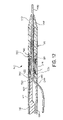
- FIG. 13 is a sectional view of a delivery system according to a sixth exemplary embodiment of the invention.
- FIG. 14 is a magnified cross-sectional view of the delivery system illustrated in FIG. 13 , taken along line 14 - 14 .
- FIG. 15 is a sectioned partial view of a body vessel containing the delivery system illustrated in FIG. 13 disposed on a wireguide with an expandable prosthetic device in a fully deployed configuration.
- FIG. 16 is a sectional view of a delivery system according to a seventh exemplary embodiment of the invention.
- FIG. 17 is a flow diagram of a method of making a delivery system according to the invention.
- FIGS. 1 through 4 illustrate a delivery system 10 according to a first exemplary embodiment of the invention.
- the delivery system 10 includes an elongate tubular member 12 , a distal tip member 14 , a pusher 16 , and a means for retaining a proximal portion of the distal tip member 14 within the tubular member 12 .
- the means for retaining comprises a cap member 18 disposed on the tubular member 12 .
- the tubular member 12 can be any suitable tubular member, such as a sheath formed of plastic or other suitable material. Other examples of suitable tubular members include introducers, guiding catheters, and endoscopes.
- the tubular member has inner 22 and outer 24 surfaces and defines a passageway 26 extending from a proximal end 28 to a distal end 30 .
- the passageway 26 provides a space within which other components of the delivery system 10 can be disposed.
- the proximal end 28 can include any desirable connectors and/or adaptors, such as a threaded fitting 32 , Touhy-Borst adapter, and other suitable connectors and adaptors.
- a handle or handle system configured to allow sliding of the pusher 16 relative to the tubular member 12 , or vice versa, could be attached to the proximal end 28 of the tubular member 12 .
- the tubular member 12 can indeed comprise a simple tubular body.
- the tubular member 12 defines a distal cavity 34 that receives a portion of the distal tip member 14 .
- the distal cavity 34 is a portion of and is continuous with the passageway 26 .
- the inner diameter of the tubular member 12 at the distal cavity 34 is larger than the inner diameter of the tubular member 12 at at least one other portion of the tubular member 12 , such as at a portion proximal to the distal cavity 34 .
- the enlarged inner diameter of the tubular member 12 at the distal cavity 34 is formed by a relatively thin wall thickness of the tubular member 12 . As best illustrated in FIG.
- the wall 36 of the tubular member 12 includes a first portion 38 having a first wall thickness and a second portion 40 having a second wall thickness.
- the second wall thickness is less than the first wall thickness.
- a transition region 42 of the wall 36 is disposed between the first 38 and second 40 portions of the wall 36 , and includes a wall thickness that varies from the first wall thickness to the second wall thickness.
- this configuration of the tubular member is advantageous at least because it provides a desired distal cavity 34 for receiving a portion of the distal tip member 14 and the transition region 42 provides a means for limiting axial movement of the distal tip member 14 within the passageway 26 .
- the tubular member 12 defines an exchange port 44 through which a wireguide 120 can be passed.
- wireguide refers to elongate members used in minimally invasive procedures to define a path along which other devices can be advanced. In this context, the term is considered equivalent to the term “guidewire”.
- the exchange port 44 provides a communicative passageway between the passageway 26 defined by the tubular member 12 and the external environment of the tubular member 12 .
- the exchange port 44 comprises an opening through the wall 36 of the tubular member 12 .
- the exchange port can have any suitable size and configuration, and the specific size and configuration chosen for any particular embodiment of the invention will depend on several factors, including the diameter(s) of any wireguide(s) with which a particular delivery system will be used.
- the wall 36 of the tubular member can define a rounded edge 46 on the distal side of the exchange port 44 .
- the rounded edge 46 facilitates movement of the delivery system 10 over the wireguide 120 .
- the distal tip member 14 provides a structure for carrying an expandable prosthetic device 110 .
- the distal tip member 14 comprises a separate member from the tubular member 12 .
- the distal tip member 14 has proximal 50 and distal 52 ends and defines a passageway 54 extending between the ends 50 , 52 .
- the passageway 54 is adapted to receive a portion of a wireguide 120 , and can have any suitable size and configuration.
- the specific size and configuration chosen for any particular embodiment of the invention will depend on several considerations, including the diameter(s) of any wireguide(s) with which a particular delivery system will be used.
- the distal tip member 14 provides a proximal surface 56 at the proximal end 50 that is able to interact with a surface 94 of the pusher 16 .
- An opening 58 is defined at the proximal end 50 and provides access to the passageway 54 .
- the distal end 52 provides a tapered surface 60 and defines an opening 62 that also provides access to the passageway 54 .
- the tapered surface 60 provides a smaller profile to the distal end 52 of the distal tip member 14 , which facilitates navigation of the delivery system 10 through body vessels.
- the distal tip member 14 comprises a tip body 64 and a tubular member 66 .
- the tip body 64 and tubular member 66 can comprise separate members. These two portions of the distal tip member 14 can also be integrally formed as a unitary structure.
- the tip body 64 includes a main body 68 and a tapered portion 70 .
- the main body is a substantially cylindrical portion and advantageously has an outer diameter that is slightly larger than the outer diameter of the tubular member 12 , although this is not required.
- the tapered portion 70 provides the desirable tapered surface 60 .
- the tubular member 66 defines a flange 72 that provides the desired surface 56 for interaction with the pusher 16 of the delivery system 10 . As best illustrated in FIG.
- the outer diameter of the flange 72 is advantageously sized to be slightly less than the inner diameter of the tubular member 12 at the distal cavity 34 and slightly greater than the inner diameter of the tubular member 12 at a portion proximal to the transition region 42 .
- This configuration of the flange 72 is advantageous at least because it provides the desired surface 56 for interaction with the pusher 16 and it acts to limit axial movement of the distal tip member 14 within the passageway 26 of the tubular member 12 .
- the flange 72 can be integrally formed with the tubular member 66 of the distal tip member 14 , or can comprise a separately attached member. It is noted that the pusher 16 can interact with the proximal surface 56 of the distal tip member at any point or points on the surface 56 , including points on the periphery of the surface 56 as well as centrally-located points.
- the distal tip member 14 defines a mounting region 74 on which a self-expandable prosthetic device can be disposed.
- the mounting region 74 is a portion of the distal tip member 14 that is able to receive an expandable prosthetic device 110 and need not have any particular structural features.
- the mounting region 74 comprises a portion of an external surface of the tubular member 66 disposed between the flange 72 and the proximal end of the tip body 64 .
- Two or more self-expandable prosthetic devices could also be disposed on the mounting region 74 .
- the distal tip member 14 could be configured to define multiple mounting regions, either continuous with or discreet from the other mounting region(s). Delivery systems according to these embodiments could be used to deploy multiple self-expandable prosthetic devices.
- the pusher 16 or another component could be configured to provide information relating to the deployment status of one or more of the multiple self-expandable prosthetic devices.
- the distal tip member 14 can be formed of any suitable material or materials, and the specific material or materials chosen will depend on several considerations, including the intended application of the delivery system 10 .
- the tip body 64 is formed of a flexible polymeric material, such as polyurethane. Any suitable pliant material can be used to form the tip body, including flexible polymers, gels, and similar materials.
- the tubular member 66 is formed from a relatively hard plastic or other polymeric material, and the tip body 64 is disposed on the tubular member 66 .
- the flange 72 of this embodiment is integrally formed by the tubular member 66 .
- the pusher 16 is an elongate member adapted to be substantially disposed within the passageway 26 of the tubular member 12 .
- the pusher 16 comprises a main body 80 and has proximal 82 and distal 84 ends.
- a flange 86 or other structure can be disposed at the proximal end 82 to provide a connector, adapter, or to limit axial movement of the pusher 16 within the passageway 26 of the tubular member 12 .
- the pusher 16 of this embodiment includes a distal portion 88 having a reduced width as compared to that of the main body 80 . As best illustrated in FIG.
- this reduced width at the distal portion 88 creates a void region 90 when the pusher 16 is disposed in the passageway 26 of the tubular member 12 .
- the pusher 16 of the illustrated embodiment includes ogee 92 that transitions the width of the pusher between the larger and smaller widths and partially defines the void region 90 within the tubular member 12 .
- the void region 90 can accommodate a portion of a wireguide 120 as the pusher 16 is advanced axially toward the distal end 30 of the tubular member 12 .
- the distal end 84 of the pusher 16 defines a pushing surface 94 adapted to transfer a force generated by axial movement of the pusher 16 within the passageway 26 of the tubular member 12 onto the proximal surface 56 of the distal tip member 14 .
- the pushing surface 94 advantageously lies in a plane that is substantially parallel to a plane in which the proximal surface 56 of the distal tip member 14 lies.
- the pushing surface 94 can have any suitable size and configuration, including the semi-circular configuration illustrated in FIGS. 1 through 4 .
- the pusher 16 as best illustrated in FIG. 2 , can be attached to the proximal end 50 of the distal tip member 14 , such as by an adhesive, weld, or other suitable means 91 for attaching two members.
- the pusher 16 and the distal tip member 14 can comprise separate, non-attached members. Attachment of these two members, while optional, is considered advantageous at least because it prevents complete escape of the distal tip member 14 from the tubular member 12 .
- the pusher 16 can be formed of any suitable material, including plastics and other polymeric materials, and metals. Furthermore, the pusher 16 can include other structural features as desired. For example, it may be advantageous to form the pusher 16 to include a lumen that provides communication to the passageway 26 of the tubular member 12 . Also, the pusher 16 can have any suitable structure that allows it to accommodate a portion of a wireguide 120 disposed within the tubular member 12 . For example, a pusher with a substantially uniform width could be used. In this embodiment, one or more sufficiently stiff wires or other members could be made to project outward from a distal end of the pusher. The wires could be used to interact with the proximal surface 56 of the distal tip member 14 while still accommodating a portion of a wireguide.
- the delivery system 10 includes a means for retaining a proximal portion of the distal tip member 14 within the tubular member 12 .
- Any suitable means can be used, and a variety of suitable structures are described herein.
- the means for retaining a proximal portion of the distal tip member 14 within the tubular member 12 comprises a cap member 18 disposed on the distal end 30 of the tubular member 12 .
- the cap member 18 is a ring-like structure defining a recess 96 and an opening 98 .
- the recess 96 is adapted to substantially receive a portion of the wall 36 of the tubular member 12 .
- the opening 98 is sized and configured to permit passage of a first portion of the distal tip member 14 and prevent passage of a second portion of the distal tip member 14 .
- the opening 98 of the cap member 18 in the exemplary embodiment is sized and configured to permit through passage of the tubular member 66 of the distal tip member 14 and to prevent through passage of the tip body 64 .
- the opening 98 is sized and configured to prevent through passage of the flange 72 .
- the cap member 18 defines an interior surface. This surface 13 can be disposed at an angle to the inner surface 22 of the tubular member 12 . Any suitable angle can be used, and the specific angle chosen for a particular embodiment will depend on several considerations, including the type of self-expandable prosthetic device with which the delivery system is intended to be used. The angle should be sufficient to provide the desired means for retaining a proximal portion of the distal tip member 14 within the tubular member 12 . An angle that places the interior surface in a position relative to the inner surface 22 that does not significantly interfere with passage of the expandable prosthetic device 110 from the passageway 26 of the tubular member 12 to the environment external to the tubular member 12 is desirable.
- the cap member 18 can be formed of any suitable material, including plastic and other polymeric materials. It may be advantageous to form the cap member 18 of the same material as the tubular member 12 as this may provide desirable attachment properties between these two structures.
- the cap member 18 could also be formed of metals and other radiopaque materials. These materials may be advantageous in embodiments for which visibility is desired during use, such as under fluoroscopy during treatment techniques.
- the cap member 18 is attached to the distal end 30 of the tubular member 12 , and can be attached by any suitable means for attaching two members together, including adhesives, threaded and other mated fittings, and structural connectors such as rivets. Also, various attachment techniques, such as welding and melt-forming, can be used.
- the distal interior surface 117 of the cap member 18 is complimentary to a proximal shoulder 119 of the tip body 64 .
- the tip body 64 must pass through, or at least near, the prosthetic device 110 .
- the proximal shoulder is considered advantageous at least because it substantially eliminates a surface edge that may engage the prosthetic device 110 during withdrawal.
- a self-expandable prosthetic device can be disposed on the mounting region 74 of the distal tip member 14 .
- Any suitable type of self-expandable prosthetic device can be used with the delivery systems according to the invention, including self-expandable stents, prosthetic valves that include a self-expandable support frame, such as prosthetic valves for implantation in a vein (prosthetic venous valves), self-expandable filters, distal protection devices, vessel occluders, and other self-expandable devices.
- Suitable self-expandable prosthetic devices for use with delivery systems according to the invention include those described in U.S. Pat. No. 6,200,336 to Pavcnik et al. for a MULTIPLE-SIDED INTRALUMINAL MEDICAL DEVICE; United States Application for patent Ser. No. 10/642,372 of Pavcnik et al. for an IMPLANTABLE VASCULAR DEVICE, filed on Aug. 15, 2003; and United States Application for patent Ser. No. 10/828,716 of Case et al. for an ARTIFICIAL VALVE PROSTHESIS WITH IMPROVED FLOW DYNAMICS, filed on Apr.
- FIGS. 2 through 4 illustrate the delivery system 10 according to the first exemplary embodiment with a self-expandable prosthetic device 110 disposed on the mounting region 74 of the tubular member 66 of the distal tip member 14 .
- the illustrated self-expandable prosthetic device 110 is a self-expandable stent, but it is expressly contemplated by the inventors that this device 110 is exemplary in nature.
- a self-expandable prosthetic device 110 will tend to expand within the passageway 26 of the tubular member 12 when the device 110 is disposed on the passageway 26 .
- a means for temporarily securing the prosthetic device 110 to the distal tip member 14 can be used. Any suitable structure and/or composition can be used as the means for temporarily securing the prosthetic device 110 to the distal tip member 14 .
- the specific structure/composition chosen should secure the prosthetic device 110 so it advances within the passageway 26 upon advance of the distal tip member 14 , but should release the prosthetic device 110 upon its exiting of the passageway 26 , as best illustrated in FIG. 3 .
- two adhesive bands 112 are used as the means for temporarily securing the prosthetic device 110 to the distal tip member 14 .
- the proximal end of the prosthetic device 110 can be butted against the distal surface of the proximal end 50 of the distal tip member 14 .
- both a means for temporarily securing and an abutting positioning can be employed.
- FIG. 2 illustrates the delivery system 10 according to the first embodiment disposed on a wireguide 120 .
- the wireguide 120 is known in the art and will not be described in detail herein.
- the wireguide 120 includes a proximal portion 122 , a distal portion 124 , and an intermediate portion 126 disposed between the proximal 122 and distal 124 portions.
- the delivery system 10 is disposed on the wireguide 120 by passing an end of the wireguide 120 through an opening of the delivery system 10 , such as the opening 62 of the distal tip member 14 , and into the passageway 26 of the tubular member 12 .
- the wireguide 120 exits the passageway 26 by passing through the exchange port 44 .
- Delivery systems according to the invention are adapted for efficient exchanges for other delivery systems over a previously placed wireguide. Accordingly, during use of the delivery systems according to the invention, only a portion of a wireguide 120 is disposed in a portion of the length of the passageway 26 of the tubular member 12 .
- FIGS. 3 and 4 illustrate the delivery system 10 according to the first embodiment during two stages of deployment of an included self-expandable prosthetic device 110 .
- the self-expandable prosthetic device 110 is partially deployed.
- the self-expandable prosthetic device 110 is fully deployed.
- a review of FIGS. 3 and 4 demonstrates the functioning of the delivery system 10 according to the first embodiment of the invention.
- the delivery system 10 is disposed on a wireguide 120 that has been previously placed in a body vessel 150 .
- the wireguide 120 extends through the lumen 152 of the body vessel 150 , and can be placed according to techniques known in the art.
- the delivery system 10 has been advanced over the wireguide 120 and moved along the wireguide 120 to a desired point of treatment 154 in the body vessel 150 .
- the distal end of the wireguide 120 is typically advanced beyond the point of treatment 154 prior to deployment of the self-expandable prosthetic device 110 .
- the delivery system 10 is then advanced over the wireguide 120 until the distal end 160 is at or near the point of treatment 154 .
- the pusher 16 is moved axially toward the distal end 30 of the tubular member 12 .
- This axial movement of the pusher 16 results in axial movement of the distal tip member 14 due to interaction between the pushing surface 94 of the pusher 16 and the proximal surface 56 of the distal tip member 14 .
- the self-expandable prosthetic device 110 advances through the opening 98 of the cap member 18 .
- the self-expandable prosthetic device 110 may deflect inward as it moves along the interior surface 100 of the cap member 18 .
- FIG. 3 illustrates the self-expandable prosthetic device 110 in a partially deployed state.
- the self-expandable prosthetic device 110 can also be deployed by retracting the tubular member 12 over the pusher 16 while substantially maintaining the position of the pusher 16 .
- the retraction of the tubular member 12 gradually reveals the mounting region 74 , resulting in deployment of the self-expandable prosthetic device 110 .
- FIG. 4 illustrates the self-expandable prosthetic device 110 in a fully deployed state.
- the cap member 18 retains a proximal portion of the distal tip member 14 within the tubular member 12 .
- the flange 72 of the distal tip member 14 is prevented from passing through the opening 98 of the cap member 18 because the outer diameter of the flange 72 is larger than the inner diameter of the opening 98 .
- the delivery system 10 is withdrawn from the body vessel 150 .
- Withdrawal can be accomplished in a variety of manners. For example, the entire assembly, including the wireguide 120 , can be withdrawn as a single unit. This may be desirable if it is known that there is no need to pass another delivery system over the wireguide 120 . If, however, it may be necessary to pass another delivery system over the wireguide 120 and the delivery system 10 , the user can withdrawal the delivery system 10 while leaving the wireguide 120 in its position within the body vessel 150 .
- the user fixes the wireguide 120 in position relative to the body vessel 150 , such as by holding the wireguide 120 with a hand or attaching a proximal portion of the wireguide 120 to the patient, e.g., taping the wireguide 120 to the skin of the patient.
- a locking device that fixes the wireguide in position relative to the body vessel can be used.
- the intermediate portion 126 of the wireguide 120 moves through the exchange port 44 of the tubular member 12 , through the distal cavity 34 , through the passageway 54 of the distal tip member 14 , and through the opening 62 at the distal end 52 of the distal tip member 14 .
- the proximal end (not illustrated in the Figures) of the wireguide 120 passes through the delivery system 10 in the same manner as the intermediate portion 126 and exits the opening 62 at the distal end 52 of the distal tip member 14 .
- the delivery system 10 is free of the wireguide 120 , and the wireguide 120 has remained in position within the lumen 152 of the body vessel 150 .
- Another delivery system can then be advanced along the wireguide 120 to the same or a different point of treatment in the body vessel 150 .
- Another technique can be used to withdraw the delivery system 10 while leaving the wireguide 120 in place.
- the position of the wireguide 120 is fixed relative to the body vessel 150 , as in the exchange technique described above.
- the delivery system 10 is advanced distally over the wireguide 120 so that the distal end (not illustrated in the Figures) of the wireguide 112 enters the opening 62 at the distal end 52 of the distal tip member 14 .
- the delivery system 10 is further advanced distally within the lumen 152 of the body vessel 150 so that the distal end of the wireguide 120 passes through the passageway 54 of the distal tip member 14 , through the distal cavity 34 of the tubular member 12 , and exits the exchange port 44 .
- the delivery system 10 is free of the wireguide 120 and can be completely withdrawn from the body vessel 150 .
- the wireguide 120 has remained in position within the lumen 152 of the body vessel 150 .
- Another delivery system can then be advanced along the wireguide 112 to the same or a different point of treatment in the body vessel 150 .
- the delivery system 10 can be maintained in substantially the same position while the wireguide 120 is retracted until the distal end of the wireguide 120 exits the exchange port 44 .
- a combination of advancing the delivery system 10 and retracting the wireguide 120 can be used.
- Embodiments of the invention for use in intraductal exchange techniques advantageously include at least one marker at or near the exchange port 44 .
- the marker should be visible under conventional visualization techniques appropriate for the intended procedure in which the delivery system 10 will be used, such as a marker visible under fluoroscopy.
- a circumferential marker disposed around the edge of the exchange port 44 is advantageous, as are spot and longitudinal markers disposed on or adjacent the edge of the exchange port 44 .
- Delivery devices according to these embodiments can be used with a wireguide that includes a marker at its distal end. This pairing allows a user to determine the point in time during the intraductal exchange procedure at which the wireguide has exited the exchange port 44 , which indicates the point in time at which it is appropriate to begin withdrawal of the delivery device 10 .
- a wireguide having an entire distal end that is radiopaque can be used.
- the proximal end of the tubular member 12 can include indicia that, in conjunction with indicia on a wireguide used with the tubular member 12 , provide information relating to the relative positions of the distal ends of the tubular member 12 and wireguides. These indicia can be useful in determining the point at which the delivery system 10 and wireguide have been uncoupled from each other.
- FIGS. 5 and 6 illustrate a delivery system 210 according to a second exemplary embodiment of the invention.
- the delivery system 210 according to this embodiment of the invention includes the tubular member 12 , distal tip member 14 , and cap member 18 according to the first exemplary embodiment. Accordingly, reference numbers in FIGS. 5 and 6 for these elements refer to similar features and/or components described above in conjunction with FIGS. 1 through 4 .
- the delivery system 210 includes a pusher 170 having a main body 172 , a proximal end (not illustrated in FIGS. 5 and 6 ), and a distal end 176 .
- FIG. 7 illustrates the pusher 170 of this embodiment free of the remaining components of the delivery system 210 .
- the proximal end 174 includes a flange 178 having an increased diameter as compared to that of the main body 172 .
- the distal end 176 provides a pushing surface 180 and defines a channel 182 .
- the channel 182 is defined by first 184 and second 186 opposing surfaces and a proximal end surface 188 , and is sized and configured to receive a portion of a wireguide 120 placed within the delivery system 210 .
- the illustrated U-shaped configuration is exemplary only.
- the channel 182 advantageously has a length that is substantially the same as or at least slightly greater than the distance between the proximal surface 56 of the distal tip member 14 and the proximal side of the exchange port 44 of the tubular member 12 when the distal tip member 14 is fully advanced distally within the tubular member 12 .
- This length for the channel 182 allows the channel 182 to receive the length of the wireguide 120 that will be within the passageway 26 of the tubular member 12 while the distal tip member 14 is fully advanced distally within the tubular member 12 .
- the proximal end surface 188 is curvilinear, such as the ogee 190 illustrated in FIG. 5 . This configuration is believed to avoid kinking or other alterations to the wireguide 120 when the pusher 170 is fully advanced distally within the tubular member 12 .
- the channel 182 receives an increasing length of the wireguide 120 .
- the pusher 170 advances the distal tip member 14 in a similar manner as described above for the first exemplary embodiment.
- FIGS. 8 and 9 illustrate a delivery system 310 according to a third exemplary embodiment of the invention.
- the delivery system according to this embodiment is similar to the embodiment illustrated in FIGS. 1 through 4 , except as indicated below.
- the delivery system 310 includes an elongate tubular member 312 , a distal tip member 314 , a pusher 316 , and a means for retaining a proximal portion of the distal tip member 314 within the tubular member 312 .
- the means for retaining comprises a cap member 318 disposed on the tubular member 312 .
- the tubular member 312 has inner 322 and outer 324 surfaces and defines a passageway 326 extending from a proximal end (not illustrated in FIGS. 8 and 9 ) to a distal end 330 .
- the tubular member 312 defines a distal cavity 334 and an exchange port 344 through which a wireguide 320 can be passed.
- the distal tip member 314 is a separate member from the tubular member 312 , and has proximal 350 and distal 352 ends and defines a passageway 354 extending between the ends 350 , 352 .
- the passageway 354 can receive a portion of the wireguide 320 .
- the distal tip member 314 defines a mounting region 374 on which an expandable medical device 311 can be disposed.
- the distal tip member 314 provides a proximal surface 356 at the proximal end 350 that is able to interact with a pushing surface 394 of the pusher 316 .
- the tubular member 312 includes a projection 315 disposed in the passageway 326 .
- the projection 315 can be defined by the tubular member 312 .
- a separate member could be attached to the tubular member 312 to form a projection.
- the projection 315 defines a ramp 317 that forces the pusher 316 into an appropriate position within the passageway 326 of the tubular member 312 as the pusher 316 is axially advanced over the projection 315 .
- the projection 315 forces the distal end 384 of the pusher 316 to a position substantially opposite the exchange port 344 . This positioning limits contact between the pusher 316 and the wireguide 320 within the passageway 316 of the tubular member 312 .
- FIGS. 10 and 11 illustrate a delivery system 410 according to a fourth exemplary embodiment of the invention.
- the delivery system 410 of this embodiment is similar to the embodiment illustrated in FIGS. 1 through 4 , except as indicated below. Accordingly, the delivery system 410 includes an elongate tubular member 412 , a distal tip member 414 , a pusher 416 , and a means for retaining a proximal portion of the distal tip member 414 within the tubular member 412 .
- the means for retaining comprises an indent 418 in the inner surface 422 of the tubular member 412 .
- the tubular member 412 has inner 422 and outer 424 surfaces and defines a passageway 426 extending from a proximal end (not illustrated in FIGS. 10 and 11 ) to a distal end 430 .
- the tubular member 412 defines a distal cavity 434 and an exchange port 444 through which a wireguide 420 can be passed.
- the distal tip member 414 is a separate member from the tubular member 412 , and has proximal 450 and distal 452 ends and defines a passageway 454 extending between the ends 450 , 452 .
- the passageway 454 can receive a portion of a wireguide 420 .
- the distal tip member 414 defines a mounting region 474 on which a self-expandable medical device 411 can be disposed.
- the distal tip member 414 provides a proximal surface 456 at the proximal end 450 that is able to interact with a pushing surface 494 of the pusher 416 .
- the proximal surface 456 of the distal tip member 414 comprises a flexible member.
- the flexible member can be integrally formed with the remainder of the distal tip member, or can comprise a separately attached member.
- the proximal surface 456 comprises a flexible section of material that is attached to a proximal end of a tubular member 466 .
- the flexible member can have any suitable size and configuration.
- the flexible member advantageously includes one or more outer portions that are sized and configured to become disposed within the indent 418 of the tubular member 412 when the proximal end 450 of the distal tip member 414 is disposed substantially adjacent the indent 418 within the tubular member 412 .
- the flexible member can be formed of any suitable material. The material chosen need only enable the member to flex sufficiently enough so that a portion of the member can become disposed within the indent 418 when the distal tip member 414 is properly disposed, as described above. Examples of suitable materials for the flexible member include natural and synthetic rubbers, polymeric materials, and other flexible materials.
- the proximal surface 456 comprises a substantially circular flexible member having a tapered outer portion 490 .
- FIG. 10 the distal tip member 414 is fully retracted into the tubular member 412 , and outer portion of the flexible member comprising the proximal surface 456 is deflected inward by the inner surface 422 of the tubular member 412 .
- FIG. 11 illustrates the delivery system 410 disposed in the lumen 152 of a body vessel 150 with the distal tip member 414 in a fully extended configuration. In this configuration, the outer portion 490 of the flexible member comprising the proximal surface 456 has deflected into the indent 418 defined by the tubular member 412 . The indent 418 engages the flexible member and retains a proximal portion of the distal tip member 414 within the tubular member 412 .
- the indent 418 advantageously comprises a circumferential indent 418 on the inner surface 422 of the tubular member 412 .
- the circumferential nature of the indent 418 provides more surface for engaging the proximal surface 456 of the distal tip member 414 .
- Other configurations can be used for the indent 418 , including a partial circumferential indent and a plurality of partial circumferential indents.
- an indent 418 as the means for retaining a proximal portion of the distal tip member 414 within the tubular member 412 may be advantageous at least because it eliminates the need for a protrusion into the passageway 426 of the tubular member 412 , such as that provided by the cap member 18 in the first exemplary embodiment. Any protrusion into the passageway 426 may introduce an obstacle into the path of an advancing self-expandable prosthetic device, which may require inward deflection to some degree by the prosthetic device during deployment. The use of the indent 418 substantially eliminates the need for any inward deflection of a prosthetic device during deployment.
- FIG. 12 illustrates a delivery system 510 according to a fifth exemplary embodiment of the invention.
- the delivery system 510 of this embodiment is similar to the embodiment illustrated in FIGS. 1 through 4 , except as indicated below. Accordingly, the delivery system 510 includes an elongate tubular member 512 , a distal tip member 514 , a pusher 516 , and a means for retaining a proximal portion of the distal tip member 514 within the tubular member 512 .
- the means for retaining comprises a ramped projection 518 on the inner surface 522 of the tubular member 512 .
- the tubular member 512 has inner 522 and outer 524 surfaces and defines a passageway 526 extending from a proximal end (not illustrated in FIG. 12 ) to a distal end 530 .
- the tubular member 512 defines a distal cavity 534 and an exchange port 544 through which a wireguide 520 can be passed.
- the distal tip member 514 is a separate member from the tubular member 512 , and has proximal 550 and distal 552 ends and defines a passageway 554 extending between the ends 550 , 552 .
- the passageway 554 can receive a portion of a wireguide 520 .
- the distal tip member 514 defines a mounting region 574 on which an expandable prosthetic device 511 can be disposed.
- the distal tip member 514 provides a proximal surface 556 at the proximal end 550 that is able to interact with a pushing surface 594 of the pusher 516 .
- the proximal surface 556 of the distal tip member 514 comprises a flange attached to the proximal end 550 of the distal tip member 514 .
- the flange is a rigid section of material, such as plastic or metal. Alternatively, a pliable material can be used. Such materials may provide advantages in manufacturing the delivery system 510 by facilitating insertion of the distal tip member 514 into the tubular member 512 .
- the ramped projection 518 defines a ramp 598 extending into the passageway 526 of the tubular member 512 .
- the height of the ramp 598 relative to the inner surface 522 of the tubular member 512 increases from the proximal side to the distal side of the ramp 518 .
- the ramped projection 518 can comprise one or more discrete projections, or can comprise a circumferential projection.
- the ramped projection 518 allows a self-expandable prosthetic device to pass out of the distal end of the tubular member 512 , while retaining a proximal portion of the distal tip member 514 within the tubular member 512 .
- FIGS. 13 through 15 illustrate a delivery system 610 according to a sixth exemplary embodiment of the invention.
- the delivery system 610 of this embodiment is similar to the embodiment illustrated in FIGS. 1 through 4 , except as indicated below.
- the delivery system 610 includes an elongate tubular member 612 , a distal tip member 614 , and a means for retaining a proximal portion of the distal tip member 614 within the tubular member 612 .
- the means for retaining comprises a track 618 in the inner surface 622 of the tubular member 612 .
- the track 618 extends from the proximal end (not illustrated in FIG. 13 ) toward the distal end 630 of the tubular member 612 .
- a fluid 616 is disposed in the passageway 626 of the tubular member 612 .
- the tubular member 612 has inner 622 and outer 624 surfaces and defines a passageway 626 extending from a proximal end (not illustrated in FIG. 13 ) to a distal end 630 .
- the tubular member 612 defines a distal cavity 634 and an exchange port 644 through which a wireguide 620 can be passed.
- a seal 660 is disposed in the exchange port 644 and is adapted to prevent leakage of the fluid 616 from the passageway 626 while permitting passage of a wireguide 620 through the exchange port 644 .
- a self-sealing rubber or polymeric member with one or more narrow slits can be used as the seal 660 .
- the track 618 comprises a recess in the inner surface 622 of the tubular member.
- the track 618 can have any suitable configuration, and need only be able to receive corresponding structural features of the distal tip member 614 as described below.
- the track 618 advantageously has a length that extends from a position distal to the distal side of the exchange port 644 to a position proximal to the distal end 630 of the tubular member 612 . In the illustrated embodiment, the length of the track 618 is slightly greater than the length of the mounting region 674 of the distal tip member 614 .
- the track 618 should terminate proximal to the distal end 630 of the tubular member 612 .
- the distal end of the track 618 can comprise a portion of the wall 636 of the tubular member 612 , or can comprise a separate member disposed within the track 618 .
- a distal cap 690 can be used to terminate the track 618 .
- the inner surface 622 of the tubular member 612 can define any suitable number of tracks 618 .
- the number chosen should correspond to the number of projections 680 on the proximal surface 656 of the distal tip member 614 , as described below.
- the inner surface 622 defines two tracks 618
- the proximal surface 656 of the distal tip member 614 includes two projections 680 , each of which is disposed within a single track 618 .
- the use of two or more tracks 618 and projections 680 may enhance the durability of the delivery system by providing multiple points of interaction between the elongate tubular member 612 and the distal tip member 614 .
- the distal tip member 614 is a separate member from the tubular member 612 , and has proximal 650 and distal 662 ends and defines a passageway 654 extending between the ends 650 , 662 .
- the passageway 654 can receive a portion of a wireguide 620 .
- the distal tip member 614 defines a mounting region 674 on which an expandable prosthetic device 611 can be disposed.
- the distal tip member 614 provides a proximal surface 656 at the proximal end 650 .
- the proximal surface 656 provides a surface against which the fluid 616 can exert a force to effect axial movement of the distal tip member 614 .
- the proximal surface 656 of the distal tip member 614 comprises a flange on the proximal end 650 of the distal tip member 614 .
- the flange is a rigid section of material, such as plastic or metal.
- the flange defines one or more projections 680 that are disposed within the track 618 of the tubular member 612 .
- the flange defines an appropriate number of projections 680 based upon the number of tracks 618 in the inner surface 622 of the tubular member 612 .
- a distal cap 690 is positioned on the distal end 630 of the tubular member 612 and prevents escape of the distal tip member 614 from the tubular member 612 .
- the distal cap 690 is advantageously snap-fit onto the distal end 630 . This facilitates manufacturing by allowing the proximal end 650 to be disposed in the tubular member 612 and subsequently captured there by attachment of the distal cap 690 .
- any other suitable connection can be used, including threaded connections, adhesives, welds, and the like.
- FIG. 15 illustrates the delivery device 610 according to this embodiment with the distal tip member 614 in a fully advanced position. Pressure has been applied to the fluid 616 , which in turn has placed pressure on the proximal surface 656 of the distal tip member 614 . Pressure can be applied to the fluid 616 in any suitable manner, such as by introducing additional fluid into an opening at the proximal end of the tubular member 612 via a fluid delivery device, such as a syringe attached to the tubular member 612 . Also, a bladder could be used with the tubular member 612 , such as a bladder disposed within an opening in a wall of the tubular member 612 .
- a positive pressure applied to the fluid will cause the distal tip member 614 to move axially in a distal direction.
- the projections 680 move along and within the tracks 618 , until the terminal ends of the tracks 618 is reached.
- the tracks 618 cooperate with the projections 680 to retain a proximal portion of the distal tip member 614 within the tubular member 612 .
- a negative pressure could subsequently be applied to the fluid 612 to cause the distal tip member 614 to move axially in a proximal direction. That is, a vacuum can be pulled, such as with an attached syringe or similar device, to resheath the distal tip member 614 .
- the fluid 616 can comprise any suitable fluid, including liquids and gases. Saline and other biocompatible fluids are expected to be advantageous.
- an indicia that correlates a known volume of the fluid 616 with an axial distance traveled by the distal tip member 614 could be included.
- an attached syringe can include indicia that provide information relating to the axial movement of the distal tip member 614 relative to a particular volume of fluid 616 passed into the tubular member 612 .
- the indicia can also be configured to provide information relative to the deployment state of a self-expandable prosthetic device disposed on the distal tip member 614 .
- a ramped surface 692 can be disposed on the inner surface of the tubular member 612 to aid in guidance of a wireguide 620 through the exchange port 644 and the passageway 654 of the distal tip member 614 .
- FIG. 16 illustrates a delivery system 710 according to a seventh exemplary embodiment of the invention.
- the delivery system 710 of this embodiment is similar to the embodiment illustrated in FIGS. 1 through 4 , except as indicated below. Accordingly, the delivery system 710 includes an elongate tubular member 712 , a distal tip member 714 , a pusher 716 , and a means for retaining a proximal portion of the distal tip member 714 within the tubular member 712 .
- the means for retaining comprises a cap member 718 disposed on the tubular member 712 .
- the cap member 718 of this embodiment is similar to the cap member 118 described above for the first exemplary embodiment.
- the tubular member has inner 722 and outer 724 surfaces and defines a passageway 726 extending from a proximal end (not illustrated in FIG. 16 ) to a distal end 730 .
- the passageway 726 includes a distal cavity 734 that receives a portion of the distal tip member 714 .
- the tubular member also defines an exchange port 744 that comprises an opening through the wall 736 of the tubular member 712 and provides a communicative passageway between the passageway 726 defined by the tubular member 712 and the external environment of the tubular member 712 .
- the tubular member 712 includes a reinforcing coil 748 .
- the coil 748 can comprise a metal coil disposed on a surface of the tubular member 712 or embedded within the tubular member 712 .
- the coil 748 provides a stiffening support to the tubular member 712 and may enhance the pushability and torqueability of the tubular member 712 .
- the tubular member 712 has a first wall portion 738 , which has a first thickness, and a second wall portion 740 , which has a second thickness. The first thickness is greater than the second thickness.
- the coil 748 can terminate proximal to the second portion 740 to allow for the reduced wall thickness in the second wall portion 740 .
- the coil 748 can terminate proximal to the exchange port 744 or, as illustrated in FIG. 17 , the coil 748 can extend distally beyond the exchange port 744 .
- the distal tip member 714 is a separate member from the tubular member 712 , and has proximal 750 and distal 752 ends and defines a passageway 754 extending between the ends 750 , 752 .
- the passageway 754 can receive a portion of a wireguide 720 .
- the distal tip member 714 defines a mounting region 774 on which an expandable prosthetic device 711 can be disposed.
- the distal tip member 714 also provides a proximal surface 756 at the proximal end 750 that is able to interact with a pushing surface 794 of the pusher 716 to effect axial movement of the distal tip member 714 .
- the pusher 716 is an elongate member adapted to be substantially disposed within the passageway 726 of the tubular member 712 .
- the pusher 716 comprises a main body 780 and has proximal (not illustrated in FIG. 16 ) and distal 784 ends.
- the pusher 716 of this embodiment includes a distal portion 788 having a width that is smaller than a width of a proximal portion. This reduced width at the distal portion 788 creates a void region 790 when the pusher 716 is disposed in the passageway 726 of the tubular member 712 .
- the distal end 784 of the pusher 716 defines a pushing surface 794 adapted to transfer a force generated by axial movement of the pusher 716 within the passageway 726 of the tubular member 712 onto the proximal surface 756 of the distal tip member 714 .
- the pusher 716 includes a reinforcing member 798 in a distal portion 788 of the pusher 716 .
- the reinforcing member 798 can be disposed on a surface of the pusher 716 or, as illustrated in FIG. 17 , can be embedded within the material of the pusher 716 .
- the reinforcing member 798 can comprise any suitable material, including plastic and metal, and can have any suitable size and configuration. The specific size and configuration chosen for the reinforcing member 798 for a particular embodiment of the invention will depend on several considerations, including the size and configuration of the distal portion 788 of the pusher 716 . As illustrated in FIG. 16 , the reinforcing member 798 advantageously has a length that extends proximally from a point within the distal portion 788 to a point within the portion having a width larger than that of the distal portion 788 .
- a pusher can be attached to a proximal end of a distal tip member in any embodiment using any suitable means for attaching members.
- a distal cap such as a snap-fit cap member, can be attached to the distal end of a tubular member in any embodiment to provide a means for capturing the distal tip member and preventing its complete escape from the distal end of the tubular member.
- FIG. 17 is a flow diagram of a method 800 of making a delivery system according to the invention that includes a cap member as the means for retaining a proximal portion of the distal tip member within the tubular member, such as the embodiment illustrated in FIGS. 1 through 4 .
- a distal tip member according to the invention is provided in a configuration that lacks a flange at the proximal end.
- a cap member according to the invention is provided in another step 806 .
- the cap member is passed over the proximal end of the distal tip member.
- a flange for attachment to the distal tip member is provided.
- the flange is attached to the proximal end of the distal tip member.
- a tubular member according to the invention is provided.
- the proximal end of the distal tip member is inserted into the passageway of the tubular member.
- the cap member is attached to the distal end of the tubular member.
Abstract
Description
Claims (13)
Priority Applications (2)
| Application Number | Priority Date | Filing Date | Title |
|---|---|---|---|
| US11/139,930 US7527643B2 (en) | 2004-05-28 | 2005-05-27 | Exchangeable delivery system for expandable prosthetic devices |
| US12/408,320 US20090182410A1 (en) | 2004-05-28 | 2009-03-20 | Exchangeable delivery system for expandable prosthetic devices |
Applications Claiming Priority (2)
| Application Number | Priority Date | Filing Date | Title |
|---|---|---|---|
| US57547504P | 2004-05-28 | 2004-05-28 | |
| US11/139,930 US7527643B2 (en) | 2004-05-28 | 2005-05-27 | Exchangeable delivery system for expandable prosthetic devices |
Related Child Applications (1)
| Application Number | Title | Priority Date | Filing Date |
|---|---|---|---|
| US12/408,320 Continuation US20090182410A1 (en) | 2004-05-28 | 2009-03-20 | Exchangeable delivery system for expandable prosthetic devices |
Publications (2)
| Publication Number | Publication Date |
|---|---|
| US20050267563A1 US20050267563A1 (en) | 2005-12-01 |
| US7527643B2 true US7527643B2 (en) | 2009-05-05 |
Family
ID=34982592
Family Applications (2)
| Application Number | Title | Priority Date | Filing Date |
|---|---|---|---|
| US11/139,930 Active 2027-02-15 US7527643B2 (en) | 2004-05-28 | 2005-05-27 | Exchangeable delivery system for expandable prosthetic devices |
| US12/408,320 Abandoned US20090182410A1 (en) | 2004-05-28 | 2009-03-20 | Exchangeable delivery system for expandable prosthetic devices |
Family Applications After (1)
| Application Number | Title | Priority Date | Filing Date |
|---|---|---|---|
| US12/408,320 Abandoned US20090182410A1 (en) | 2004-05-28 | 2009-03-20 | Exchangeable delivery system for expandable prosthetic devices |
Country Status (2)
| Country | Link |
|---|---|
| US (2) | US7527643B2 (en) |
| WO (1) | WO2005117758A1 (en) |
Cited By (82)
| Publication number | Priority date | Publication date | Assignee | Title |
|---|---|---|---|---|
| US20090182410A1 (en) * | 2004-05-28 | 2009-07-16 | Case Brian C | Exchangeable delivery system for expandable prosthetic devices |
| WO2012054709A1 (en) | 2010-10-20 | 2012-04-26 | Stryker Corporation | Stent delivery catheter with rapid exchange capabilities |
| US8414635B2 (en) | 1999-02-01 | 2013-04-09 | Idev Technologies, Inc. | Plain woven stents |
| US8419788B2 (en) | 2006-10-22 | 2013-04-16 | Idev Technologies, Inc. | Secured strand end devices |
| US8876881B2 (en) | 2006-10-22 | 2014-11-04 | Idev Technologies, Inc. | Devices for stent advancement |
| US8880185B2 (en) | 2010-06-11 | 2014-11-04 | Boston Scientific Scimed, Inc. | Renal denervation and stimulation employing wireless vascular energy transfer arrangement |
| US8939970B2 (en) | 2004-09-10 | 2015-01-27 | Vessix Vascular, Inc. | Tuned RF energy and electrical tissue characterization for selective treatment of target tissues |
| US8951251B2 (en) | 2011-11-08 | 2015-02-10 | Boston Scientific Scimed, Inc. | Ostial renal nerve ablation |
| US8974451B2 (en) | 2010-10-25 | 2015-03-10 | Boston Scientific Scimed, Inc. | Renal nerve ablation using conductive fluid jet and RF energy |
| US9023034B2 (en) | 2010-11-22 | 2015-05-05 | Boston Scientific Scimed, Inc. | Renal ablation electrode with force-activatable conduction apparatus |
| US9023095B2 (en) | 2010-05-27 | 2015-05-05 | Idev Technologies, Inc. | Stent delivery system with pusher assembly |
| US9028485B2 (en) | 2010-11-15 | 2015-05-12 | Boston Scientific Scimed, Inc. | Self-expanding cooling electrode for renal nerve ablation |
| US9028472B2 (en) | 2011-12-23 | 2015-05-12 | Vessix Vascular, Inc. | Methods and apparatuses for remodeling tissue of or adjacent to a body passage |
| US9050106B2 (en) | 2011-12-29 | 2015-06-09 | Boston Scientific Scimed, Inc. | Off-wall electrode device and methods for nerve modulation |
| US9060761B2 (en) | 2010-11-18 | 2015-06-23 | Boston Scientific Scime, Inc. | Catheter-focused magnetic field induced renal nerve ablation |
| US9079000B2 (en) | 2011-10-18 | 2015-07-14 | Boston Scientific Scimed, Inc. | Integrated crossing balloon catheter |
| US9084609B2 (en) | 2010-07-30 | 2015-07-21 | Boston Scientific Scime, Inc. | Spiral balloon catheter for renal nerve ablation |
| US9089350B2 (en) | 2010-11-16 | 2015-07-28 | Boston Scientific Scimed, Inc. | Renal denervation catheter with RF electrode and integral contrast dye injection arrangement |
| US9119632B2 (en) | 2011-11-21 | 2015-09-01 | Boston Scientific Scimed, Inc. | Deflectable renal nerve ablation catheter |
| US9119600B2 (en) | 2011-11-15 | 2015-09-01 | Boston Scientific Scimed, Inc. | Device and methods for renal nerve modulation monitoring |
| US9125666B2 (en) | 2003-09-12 | 2015-09-08 | Vessix Vascular, Inc. | Selectable eccentric remodeling and/or ablation of atherosclerotic material |
| US9125667B2 (en) | 2004-09-10 | 2015-09-08 | Vessix Vascular, Inc. | System for inducing desirable temperature effects on body tissue |
| US9155589B2 (en) | 2010-07-30 | 2015-10-13 | Boston Scientific Scimed, Inc. | Sequential activation RF electrode set for renal nerve ablation |
| US9162046B2 (en) | 2011-10-18 | 2015-10-20 | Boston Scientific Scimed, Inc. | Deflectable medical devices |
| US9173696B2 (en) | 2012-09-17 | 2015-11-03 | Boston Scientific Scimed, Inc. | Self-positioning electrode system and method for renal nerve modulation |
| US9186210B2 (en) | 2011-10-10 | 2015-11-17 | Boston Scientific Scimed, Inc. | Medical devices including ablation electrodes |
| US9186209B2 (en) | 2011-07-22 | 2015-11-17 | Boston Scientific Scimed, Inc. | Nerve modulation system having helical guide |
| US9192790B2 (en) | 2010-04-14 | 2015-11-24 | Boston Scientific Scimed, Inc. | Focused ultrasonic renal denervation |
| US9192435B2 (en) | 2010-11-22 | 2015-11-24 | Boston Scientific Scimed, Inc. | Renal denervation catheter with cooled RF electrode |
| US9220561B2 (en) | 2011-01-19 | 2015-12-29 | Boston Scientific Scimed, Inc. | Guide-compatible large-electrode catheter for renal nerve ablation with reduced arterial injury |
| US9220558B2 (en) | 2010-10-27 | 2015-12-29 | Boston Scientific Scimed, Inc. | RF renal denervation catheter with multiple independent electrodes |
| US9265969B2 (en) | 2011-12-21 | 2016-02-23 | Cardiac Pacemakers, Inc. | Methods for modulating cell function |
| US9277955B2 (en) | 2010-04-09 | 2016-03-08 | Vessix Vascular, Inc. | Power generating and control apparatus for the treatment of tissue |
| US9297845B2 (en) | 2013-03-15 | 2016-03-29 | Boston Scientific Scimed, Inc. | Medical devices and methods for treatment of hypertension that utilize impedance compensation |
| US9327100B2 (en) | 2008-11-14 | 2016-05-03 | Vessix Vascular, Inc. | Selective drug delivery in a lumen |
| US9326751B2 (en) | 2010-11-17 | 2016-05-03 | Boston Scientific Scimed, Inc. | Catheter guidance of external energy for renal denervation |
| US9358365B2 (en) | 2010-07-30 | 2016-06-07 | Boston Scientific Scimed, Inc. | Precision electrode movement control for renal nerve ablation |
| US9364284B2 (en) | 2011-10-12 | 2016-06-14 | Boston Scientific Scimed, Inc. | Method of making an off-wall spacer cage |
| US9408661B2 (en) | 2010-07-30 | 2016-08-09 | Patrick A. Haverkost | RF electrodes on multiple flexible wires for renal nerve ablation |
| US9420955B2 (en) | 2011-10-11 | 2016-08-23 | Boston Scientific Scimed, Inc. | Intravascular temperature monitoring system and method |
| US9433760B2 (en) | 2011-12-28 | 2016-09-06 | Boston Scientific Scimed, Inc. | Device and methods for nerve modulation using a novel ablation catheter with polymeric ablative elements |
| US9463062B2 (en) | 2010-07-30 | 2016-10-11 | Boston Scientific Scimed, Inc. | Cooled conductive balloon RF catheter for renal nerve ablation |
| US9486355B2 (en) | 2005-05-03 | 2016-11-08 | Vessix Vascular, Inc. | Selective accumulation of energy with or without knowledge of tissue topography |
| US9579030B2 (en) | 2011-07-20 | 2017-02-28 | Boston Scientific Scimed, Inc. | Percutaneous devices and methods to visualize, target and ablate nerves |
| US9649156B2 (en) | 2010-12-15 | 2017-05-16 | Boston Scientific Scimed, Inc. | Bipolar off-wall electrode device for renal nerve ablation |
| US9668811B2 (en) | 2010-11-16 | 2017-06-06 | Boston Scientific Scimed, Inc. | Minimally invasive access for renal nerve ablation |
| US9687166B2 (en) | 2013-10-14 | 2017-06-27 | Boston Scientific Scimed, Inc. | High resolution cardiac mapping electrode array catheter |
| US9693821B2 (en) | 2013-03-11 | 2017-07-04 | Boston Scientific Scimed, Inc. | Medical devices for modulating nerves |
| US9707036B2 (en) | 2013-06-25 | 2017-07-18 | Boston Scientific Scimed, Inc. | Devices and methods for nerve modulation using localized indifferent electrodes |
| US9713730B2 (en) | 2004-09-10 | 2017-07-25 | Boston Scientific Scimed, Inc. | Apparatus and method for treatment of in-stent restenosis |
| US9770606B2 (en) | 2013-10-15 | 2017-09-26 | Boston Scientific Scimed, Inc. | Ultrasound ablation catheter with cooling infusion and centering basket |
| US9808311B2 (en) | 2013-03-13 | 2017-11-07 | Boston Scientific Scimed, Inc. | Deflectable medical devices |
| US9808300B2 (en) | 2006-05-02 | 2017-11-07 | Boston Scientific Scimed, Inc. | Control of arterial smooth muscle tone |
| US9827039B2 (en) | 2013-03-15 | 2017-11-28 | Boston Scientific Scimed, Inc. | Methods and apparatuses for remodeling tissue of or adjacent to a body passage |
| US9833283B2 (en) | 2013-07-01 | 2017-12-05 | Boston Scientific Scimed, Inc. | Medical devices for renal nerve ablation |
| US9895194B2 (en) | 2013-09-04 | 2018-02-20 | Boston Scientific Scimed, Inc. | Radio frequency (RF) balloon catheter having flushing and cooling capability |
| US9907609B2 (en) | 2014-02-04 | 2018-03-06 | Boston Scientific Scimed, Inc. | Alternative placement of thermal sensors on bipolar electrode |
| US9925001B2 (en) | 2013-07-19 | 2018-03-27 | Boston Scientific Scimed, Inc. | Spiral bipolar electrode renal denervation balloon |
| US9943365B2 (en) | 2013-06-21 | 2018-04-17 | Boston Scientific Scimed, Inc. | Renal denervation balloon catheter with ride along electrode support |
| US9956033B2 (en) | 2013-03-11 | 2018-05-01 | Boston Scientific Scimed, Inc. | Medical devices for modulating nerves |
| US9962223B2 (en) | 2013-10-15 | 2018-05-08 | Boston Scientific Scimed, Inc. | Medical device balloon |
| US9974607B2 (en) | 2006-10-18 | 2018-05-22 | Vessix Vascular, Inc. | Inducing desirable temperature effects on body tissue |
| US10022182B2 (en) | 2013-06-21 | 2018-07-17 | Boston Scientific Scimed, Inc. | Medical devices for renal nerve ablation having rotatable shafts |
| US10085799B2 (en) | 2011-10-11 | 2018-10-02 | Boston Scientific Scimed, Inc. | Off-wall electrode device and methods for nerve modulation |
| US10265122B2 (en) | 2013-03-15 | 2019-04-23 | Boston Scientific Scimed, Inc. | Nerve ablation devices and related methods of use |
| US10271898B2 (en) | 2013-10-25 | 2019-04-30 | Boston Scientific Scimed, Inc. | Embedded thermocouple in denervation flex circuit |
| US10321946B2 (en) | 2012-08-24 | 2019-06-18 | Boston Scientific Scimed, Inc. | Renal nerve modulation devices with weeping RF ablation balloons |
| US10342609B2 (en) | 2013-07-22 | 2019-07-09 | Boston Scientific Scimed, Inc. | Medical devices for renal nerve ablation |
| US10398464B2 (en) | 2012-09-21 | 2019-09-03 | Boston Scientific Scimed, Inc. | System for nerve modulation and innocuous thermal gradient nerve block |
| US10413357B2 (en) | 2013-07-11 | 2019-09-17 | Boston Scientific Scimed, Inc. | Medical device with stretchable electrode assemblies |
| US10549127B2 (en) | 2012-09-21 | 2020-02-04 | Boston Scientific Scimed, Inc. | Self-cooling ultrasound ablation catheter |
| US10660698B2 (en) | 2013-07-11 | 2020-05-26 | Boston Scientific Scimed, Inc. | Devices and methods for nerve modulation |
| US10660703B2 (en) | 2012-05-08 | 2020-05-26 | Boston Scientific Scimed, Inc. | Renal nerve modulation devices |
| US10695124B2 (en) | 2013-07-22 | 2020-06-30 | Boston Scientific Scimed, Inc. | Renal nerve ablation catheter having twist balloon |
| US10722300B2 (en) | 2013-08-22 | 2020-07-28 | Boston Scientific Scimed, Inc. | Flexible circuit having improved adhesion to a renal nerve modulation balloon |
| US10835305B2 (en) | 2012-10-10 | 2020-11-17 | Boston Scientific Scimed, Inc. | Renal nerve modulation devices and methods |
| US10945786B2 (en) | 2013-10-18 | 2021-03-16 | Boston Scientific Scimed, Inc. | Balloon catheters with flexible conducting wires and related methods of use and manufacture |
| US10952790B2 (en) | 2013-09-13 | 2021-03-23 | Boston Scientific Scimed, Inc. | Ablation balloon with vapor deposited cover layer |
| US11000679B2 (en) | 2014-02-04 | 2021-05-11 | Boston Scientific Scimed, Inc. | Balloon protection and rewrapping devices and related methods of use |
| US11202671B2 (en) | 2014-01-06 | 2021-12-21 | Boston Scientific Scimed, Inc. | Tear resistant flex circuit assembly |
| US11246654B2 (en) | 2013-10-14 | 2022-02-15 | Boston Scientific Scimed, Inc. | Flexible renal nerve ablation devices and related methods of use and manufacture |
| US11331208B2 (en) | 2013-03-05 | 2022-05-17 | Cook Medical Technologies Llc | Inner catheter with a pusher band |
Families Citing this family (15)
| Publication number | Priority date | Publication date | Assignee | Title |
|---|---|---|---|---|
| JP4262631B2 (en) * | 2004-01-13 | 2009-05-13 | オリンパス株式会社 | Ultrasonic treatment device |
| WO2006089517A1 (en) * | 2005-02-25 | 2006-08-31 | Ernst-Peter Strecker | Implanting a self-expanding stent by means of hydraulic power |
| DE102006039823A1 (en) * | 2005-02-25 | 2008-03-20 | Strecker, Ernst Peter, Prof. Dr. med. | Catheter-stent-device for treatment of e.g. body hollow organ, has catheter surrounding stent, where catheter and stent are movable by difference of pressure developed by pressuring medium consisting of liquid or gas for implanting stent |
| US20060229657A1 (en) * | 2005-03-30 | 2006-10-12 | Wasicek Lawrence D | Single operator exchange embolic protection filter |
| WO2006113863A2 (en) * | 2005-04-20 | 2006-10-26 | Cook Incorporated | Medical apparatus for rapid insertion |
| US9480589B2 (en) * | 2005-05-13 | 2016-11-01 | Boston Scientific Scimed, Inc. | Endoprosthesis delivery system |
| US8992545B2 (en) * | 2006-09-28 | 2015-03-31 | W.L. Gore & Associates, Inc. | Implant-catheter attachment mechanism using snare and method of use |
| JP2008099877A (en) * | 2006-10-19 | 2008-05-01 | Olympus Medical Systems Corp | Stent delivery system |
| DE102009019823A1 (en) * | 2009-05-04 | 2010-11-11 | Acancis Gmbh & Co. Kg | Medical catheter, medical system with such a catheter and charging device for producing such a catheter |
| WO2011022658A1 (en) | 2009-08-20 | 2011-02-24 | Cook Incorporated | Loading apparatus and system for expandable intraluminal medical devices |
| US8771335B2 (en) | 2009-09-21 | 2014-07-08 | Boston Scientific Scimed, Inc. | Rapid exchange stent delivery system |
| KR101650515B1 (en) * | 2014-10-29 | 2016-08-23 | 주식회사 엠아이텍 | Catheter for surgical operation |
| WO2017049314A1 (en) * | 2015-09-18 | 2017-03-23 | Microvention, Inc. | Pushable implant delivery system |
| US20210259836A1 (en) | 2018-07-06 | 2021-08-26 | Cook Medical Technologies Llc | Storage devices, loading devices, delivery systems, kits, and associated methods |
| US11944558B2 (en) * | 2021-08-05 | 2024-04-02 | Covidien Lp | Medical device delivery devices, systems, and methods |
Citations (10)
| Publication number | Priority date | Publication date | Assignee | Title |
|---|---|---|---|---|
| US4762129A (en) | 1984-11-23 | 1988-08-09 | Tassilo Bonzel | Dilatation catheter |
| US5591194A (en) | 1994-02-18 | 1997-01-07 | C. R. Bard, Inc. | Telescoping balloon catheter and method of use |
| US5772669A (en) * | 1996-09-27 | 1998-06-30 | Scimed Life Systems, Inc. | Stent deployment catheter with retractable sheath |
| US6200336B1 (en) | 1998-06-02 | 2001-03-13 | Cook Incorporated | Multiple-sided intraluminal medical device |
| WO2003003944A2 (en) | 2001-07-06 | 2003-01-16 | Angiomed Gmbh & Co. Medizintechnik Kg | Delivery system having a rapid pusher assembly for self-expanding stent, and stent exchange configuration |
| US20030109886A1 (en) | 2001-06-27 | 2003-06-12 | Martin Keegan | Catheter |
| US20040064067A1 (en) | 2002-10-01 | 2004-04-01 | Scimed Life Systems, Inc. | Fluid pressure-actuated medical device |
| US20040073230A1 (en) | 1999-01-28 | 2004-04-15 | Ansamed Limited | Catheter with an expandable end portion |
| US7175650B2 (en) * | 2002-09-09 | 2007-02-13 | Abbott Laboratories Vascular Enterprises Limited | Self-expanding stent delivery system |
| US7309350B2 (en) * | 2001-12-03 | 2007-12-18 | Xtent, Inc. | Apparatus and methods for deployment of vascular prostheses |
Family Cites Families (10)
| Publication number | Priority date | Publication date | Assignee | Title |
|---|---|---|---|---|
| US7628803B2 (en) * | 2001-02-05 | 2009-12-08 | Cook Incorporated | Implantable vascular device |
| DE60115821T2 (en) * | 2000-10-13 | 2006-08-31 | Medtronic AVE, Inc., Santa Rosa | Hydraulic stent delivery system |
| US6616680B1 (en) * | 2000-11-01 | 2003-09-09 | Joseph M. Thielen | Distal protection and delivery system and method |
| US7182779B2 (en) * | 2001-12-03 | 2007-02-27 | Xtent, Inc. | Apparatus and methods for positioning prostheses for deployment from a catheter |
| AU2003237570A1 (en) * | 2002-05-13 | 2003-11-11 | Salviac Limited | Catheter system with procedural catheter and embolic proctection system |
| US20040167566A1 (en) * | 2003-02-24 | 2004-08-26 | Scimed Life Systems, Inc. | Apparatus for anchoring an intravascular device along a guidewire |
| US8221492B2 (en) * | 2003-04-24 | 2012-07-17 | Cook Medical Technologies | Artificial valve prosthesis with improved flow dynamics |
| US7527643B2 (en) * | 2004-05-28 | 2009-05-05 | Cook Incorporated | Exchangeable delivery system for expandable prosthetic devices |
| DE602006011721D1 (en) * | 2005-03-24 | 2010-03-04 | Cook Inc | INTERCHANGEABLE DISCHARGE SYSTEM WITH DISTAL PROTECTION |
| US8012198B2 (en) * | 2005-06-10 | 2011-09-06 | Boston Scientific Scimed, Inc. | Venous valve, system, and method |
-
2005
- 2005-05-27 US US11/139,930 patent/US7527643B2/en active Active
- 2005-05-27 WO PCT/US2005/018781 patent/WO2005117758A1/en active Application Filing
-
2009
- 2009-03-20 US US12/408,320 patent/US20090182410A1/en not_active Abandoned
Patent Citations (11)
| Publication number | Priority date | Publication date | Assignee | Title |
|---|---|---|---|---|
| US4762129A (en) | 1984-11-23 | 1988-08-09 | Tassilo Bonzel | Dilatation catheter |
| US4762129B1 (en) | 1984-11-23 | 1991-07-02 | Tassilo Bonzel | |
| US5591194A (en) | 1994-02-18 | 1997-01-07 | C. R. Bard, Inc. | Telescoping balloon catheter and method of use |
| US5772669A (en) * | 1996-09-27 | 1998-06-30 | Scimed Life Systems, Inc. | Stent deployment catheter with retractable sheath |
| US6200336B1 (en) | 1998-06-02 | 2001-03-13 | Cook Incorporated | Multiple-sided intraluminal medical device |
| US20040073230A1 (en) | 1999-01-28 | 2004-04-15 | Ansamed Limited | Catheter with an expandable end portion |
| US20030109886A1 (en) | 2001-06-27 | 2003-06-12 | Martin Keegan | Catheter |
| WO2003003944A2 (en) | 2001-07-06 | 2003-01-16 | Angiomed Gmbh & Co. Medizintechnik Kg | Delivery system having a rapid pusher assembly for self-expanding stent, and stent exchange configuration |
| US7309350B2 (en) * | 2001-12-03 | 2007-12-18 | Xtent, Inc. | Apparatus and methods for deployment of vascular prostheses |
| US7175650B2 (en) * | 2002-09-09 | 2007-02-13 | Abbott Laboratories Vascular Enterprises Limited | Self-expanding stent delivery system |
| US20040064067A1 (en) | 2002-10-01 | 2004-04-01 | Scimed Life Systems, Inc. | Fluid pressure-actuated medical device |
Cited By (106)
| Publication number | Priority date | Publication date | Assignee | Title |
|---|---|---|---|---|
| US8876880B2 (en) | 1999-02-01 | 2014-11-04 | Board Of Regents, The University Of Texas System | Plain woven stents |
| US8974516B2 (en) | 1999-02-01 | 2015-03-10 | Board Of Regents, The University Of Texas System | Plain woven stents |
| US8414635B2 (en) | 1999-02-01 | 2013-04-09 | Idev Technologies, Inc. | Plain woven stents |
| US9925074B2 (en) | 1999-02-01 | 2018-03-27 | Board Of Regents, The University Of Texas System | Plain woven stents |
| US9510901B2 (en) | 2003-09-12 | 2016-12-06 | Vessix Vascular, Inc. | Selectable eccentric remodeling and/or ablation |
| US10188457B2 (en) | 2003-09-12 | 2019-01-29 | Vessix Vascular, Inc. | Selectable eccentric remodeling and/or ablation |
| US9125666B2 (en) | 2003-09-12 | 2015-09-08 | Vessix Vascular, Inc. | Selectable eccentric remodeling and/or ablation of atherosclerotic material |
| US20090182410A1 (en) * | 2004-05-28 | 2009-07-16 | Case Brian C | Exchangeable delivery system for expandable prosthetic devices |
| US9713730B2 (en) | 2004-09-10 | 2017-07-25 | Boston Scientific Scimed, Inc. | Apparatus and method for treatment of in-stent restenosis |
| US9125667B2 (en) | 2004-09-10 | 2015-09-08 | Vessix Vascular, Inc. | System for inducing desirable temperature effects on body tissue |
| US8939970B2 (en) | 2004-09-10 | 2015-01-27 | Vessix Vascular, Inc. | Tuned RF energy and electrical tissue characterization for selective treatment of target tissues |
| US9486355B2 (en) | 2005-05-03 | 2016-11-08 | Vessix Vascular, Inc. | Selective accumulation of energy with or without knowledge of tissue topography |
| US9808300B2 (en) | 2006-05-02 | 2017-11-07 | Boston Scientific Scimed, Inc. | Control of arterial smooth muscle tone |
| US9974607B2 (en) | 2006-10-18 | 2018-05-22 | Vessix Vascular, Inc. | Inducing desirable temperature effects on body tissue |
| US10213252B2 (en) | 2006-10-18 | 2019-02-26 | Vessix, Inc. | Inducing desirable temperature effects on body tissue |
| US10413356B2 (en) | 2006-10-18 | 2019-09-17 | Boston Scientific Scimed, Inc. | System for inducing desirable temperature effects on body tissue |
| US8876881B2 (en) | 2006-10-22 | 2014-11-04 | Idev Technologies, Inc. | Devices for stent advancement |
| US10470902B2 (en) | 2006-10-22 | 2019-11-12 | Idev Technologies, Inc. | Secured strand end devices |
| US9895242B2 (en) | 2006-10-22 | 2018-02-20 | Idev Technologies, Inc. | Secured strand end devices |
| US9408729B2 (en) | 2006-10-22 | 2016-08-09 | Idev Technologies, Inc. | Secured strand end devices |
| US9629736B2 (en) | 2006-10-22 | 2017-04-25 | Idev Technologies, Inc. | Secured strand end devices |
| US9408730B2 (en) | 2006-10-22 | 2016-08-09 | Idev Technologies, Inc. | Secured strand end devices |
| US8966733B2 (en) | 2006-10-22 | 2015-03-03 | Idev Technologies, Inc. | Secured strand end devices |
| US8739382B2 (en) | 2006-10-22 | 2014-06-03 | Idev Technologies, Inc. | Secured strand end devices |
| US9149374B2 (en) | 2006-10-22 | 2015-10-06 | Idev Technologies, Inc. | Methods for manufacturing secured strand end devices |
| US8419788B2 (en) | 2006-10-22 | 2013-04-16 | Idev Technologies, Inc. | Secured strand end devices |
| US9585776B2 (en) | 2006-10-22 | 2017-03-07 | Idev Technologies, Inc. | Secured strand end devices |
| US9327100B2 (en) | 2008-11-14 | 2016-05-03 | Vessix Vascular, Inc. | Selective drug delivery in a lumen |
| US9277955B2 (en) | 2010-04-09 | 2016-03-08 | Vessix Vascular, Inc. | Power generating and control apparatus for the treatment of tissue |
| US9192790B2 (en) | 2010-04-14 | 2015-11-24 | Boston Scientific Scimed, Inc. | Focused ultrasonic renal denervation |
| US9023095B2 (en) | 2010-05-27 | 2015-05-05 | Idev Technologies, Inc. | Stent delivery system with pusher assembly |
| US8880185B2 (en) | 2010-06-11 | 2014-11-04 | Boston Scientific Scimed, Inc. | Renal denervation and stimulation employing wireless vascular energy transfer arrangement |
| US9358365B2 (en) | 2010-07-30 | 2016-06-07 | Boston Scientific Scimed, Inc. | Precision electrode movement control for renal nerve ablation |
| US9155589B2 (en) | 2010-07-30 | 2015-10-13 | Boston Scientific Scimed, Inc. | Sequential activation RF electrode set for renal nerve ablation |
| US9463062B2 (en) | 2010-07-30 | 2016-10-11 | Boston Scientific Scimed, Inc. | Cooled conductive balloon RF catheter for renal nerve ablation |
| US9408661B2 (en) | 2010-07-30 | 2016-08-09 | Patrick A. Haverkost | RF electrodes on multiple flexible wires for renal nerve ablation |
| US9084609B2 (en) | 2010-07-30 | 2015-07-21 | Boston Scientific Scime, Inc. | Spiral balloon catheter for renal nerve ablation |
| WO2012054709A1 (en) | 2010-10-20 | 2012-04-26 | Stryker Corporation | Stent delivery catheter with rapid exchange capabilities |
| US8540759B2 (en) | 2010-10-20 | 2013-09-24 | Stryker Corporation | Stent delivery catheter with rapid exchange capabilities |
| US8974451B2 (en) | 2010-10-25 | 2015-03-10 | Boston Scientific Scimed, Inc. | Renal nerve ablation using conductive fluid jet and RF energy |
| US9220558B2 (en) | 2010-10-27 | 2015-12-29 | Boston Scientific Scimed, Inc. | RF renal denervation catheter with multiple independent electrodes |
| US9028485B2 (en) | 2010-11-15 | 2015-05-12 | Boston Scientific Scimed, Inc. | Self-expanding cooling electrode for renal nerve ablation |
| US9848946B2 (en) | 2010-11-15 | 2017-12-26 | Boston Scientific Scimed, Inc. | Self-expanding cooling electrode for renal nerve ablation |
| US9668811B2 (en) | 2010-11-16 | 2017-06-06 | Boston Scientific Scimed, Inc. | Minimally invasive access for renal nerve ablation |
| US9089350B2 (en) | 2010-11-16 | 2015-07-28 | Boston Scientific Scimed, Inc. | Renal denervation catheter with RF electrode and integral contrast dye injection arrangement |
| US9326751B2 (en) | 2010-11-17 | 2016-05-03 | Boston Scientific Scimed, Inc. | Catheter guidance of external energy for renal denervation |
| US9060761B2 (en) | 2010-11-18 | 2015-06-23 | Boston Scientific Scime, Inc. | Catheter-focused magnetic field induced renal nerve ablation |
| US9023034B2 (en) | 2010-11-22 | 2015-05-05 | Boston Scientific Scimed, Inc. | Renal ablation electrode with force-activatable conduction apparatus |
| US9192435B2 (en) | 2010-11-22 | 2015-11-24 | Boston Scientific Scimed, Inc. | Renal denervation catheter with cooled RF electrode |
| US9649156B2 (en) | 2010-12-15 | 2017-05-16 | Boston Scientific Scimed, Inc. | Bipolar off-wall electrode device for renal nerve ablation |
| US9220561B2 (en) | 2011-01-19 | 2015-12-29 | Boston Scientific Scimed, Inc. | Guide-compatible large-electrode catheter for renal nerve ablation with reduced arterial injury |
| US9579030B2 (en) | 2011-07-20 | 2017-02-28 | Boston Scientific Scimed, Inc. | Percutaneous devices and methods to visualize, target and ablate nerves |
| US9186209B2 (en) | 2011-07-22 | 2015-11-17 | Boston Scientific Scimed, Inc. | Nerve modulation system having helical guide |
| US9186210B2 (en) | 2011-10-10 | 2015-11-17 | Boston Scientific Scimed, Inc. | Medical devices including ablation electrodes |
| US9420955B2 (en) | 2011-10-11 | 2016-08-23 | Boston Scientific Scimed, Inc. | Intravascular temperature monitoring system and method |
| US10085799B2 (en) | 2011-10-11 | 2018-10-02 | Boston Scientific Scimed, Inc. | Off-wall electrode device and methods for nerve modulation |
| US9364284B2 (en) | 2011-10-12 | 2016-06-14 | Boston Scientific Scimed, Inc. | Method of making an off-wall spacer cage |
| US9079000B2 (en) | 2011-10-18 | 2015-07-14 | Boston Scientific Scimed, Inc. | Integrated crossing balloon catheter |
| US9162046B2 (en) | 2011-10-18 | 2015-10-20 | Boston Scientific Scimed, Inc. | Deflectable medical devices |
| US8951251B2 (en) | 2011-11-08 | 2015-02-10 | Boston Scientific Scimed, Inc. | Ostial renal nerve ablation |
| US9119600B2 (en) | 2011-11-15 | 2015-09-01 | Boston Scientific Scimed, Inc. | Device and methods for renal nerve modulation monitoring |
| US9119632B2 (en) | 2011-11-21 | 2015-09-01 | Boston Scientific Scimed, Inc. | Deflectable renal nerve ablation catheter |
| US9265969B2 (en) | 2011-12-21 | 2016-02-23 | Cardiac Pacemakers, Inc. | Methods for modulating cell function |
| US9028472B2 (en) | 2011-12-23 | 2015-05-12 | Vessix Vascular, Inc. | Methods and apparatuses for remodeling tissue of or adjacent to a body passage |
| US9402684B2 (en) | 2011-12-23 | 2016-08-02 | Boston Scientific Scimed, Inc. | Methods and apparatuses for remodeling tissue of or adjacent to a body passage |
| US9037259B2 (en) | 2011-12-23 | 2015-05-19 | Vessix Vascular, Inc. | Methods and apparatuses for remodeling tissue of or adjacent to a body passage |
| US9592386B2 (en) | 2011-12-23 | 2017-03-14 | Vessix Vascular, Inc. | Methods and apparatuses for remodeling tissue of or adjacent to a body passage |
| US9174050B2 (en) | 2011-12-23 | 2015-11-03 | Vessix Vascular, Inc. | Methods and apparatuses for remodeling tissue of or adjacent to a body passage |
| US9072902B2 (en) | 2011-12-23 | 2015-07-07 | Vessix Vascular, Inc. | Methods and apparatuses for remodeling tissue of or adjacent to a body passage |
| US9186211B2 (en) | 2011-12-23 | 2015-11-17 | Boston Scientific Scimed, Inc. | Methods and apparatuses for remodeling tissue of or adjacent to a body passage |
| US9433760B2 (en) | 2011-12-28 | 2016-09-06 | Boston Scientific Scimed, Inc. | Device and methods for nerve modulation using a novel ablation catheter with polymeric ablative elements |
| US9050106B2 (en) | 2011-12-29 | 2015-06-09 | Boston Scientific Scimed, Inc. | Off-wall electrode device and methods for nerve modulation |
| US10660703B2 (en) | 2012-05-08 | 2020-05-26 | Boston Scientific Scimed, Inc. | Renal nerve modulation devices |
| US10321946B2 (en) | 2012-08-24 | 2019-06-18 | Boston Scientific Scimed, Inc. | Renal nerve modulation devices with weeping RF ablation balloons |
| US9173696B2 (en) | 2012-09-17 | 2015-11-03 | Boston Scientific Scimed, Inc. | Self-positioning electrode system and method for renal nerve modulation |
| US10398464B2 (en) | 2012-09-21 | 2019-09-03 | Boston Scientific Scimed, Inc. | System for nerve modulation and innocuous thermal gradient nerve block |
| US10549127B2 (en) | 2012-09-21 | 2020-02-04 | Boston Scientific Scimed, Inc. | Self-cooling ultrasound ablation catheter |
| US10835305B2 (en) | 2012-10-10 | 2020-11-17 | Boston Scientific Scimed, Inc. | Renal nerve modulation devices and methods |
| US11331208B2 (en) | 2013-03-05 | 2022-05-17 | Cook Medical Technologies Llc | Inner catheter with a pusher band |
| US9956033B2 (en) | 2013-03-11 | 2018-05-01 | Boston Scientific Scimed, Inc. | Medical devices for modulating nerves |
| US9693821B2 (en) | 2013-03-11 | 2017-07-04 | Boston Scientific Scimed, Inc. | Medical devices for modulating nerves |
| US9808311B2 (en) | 2013-03-13 | 2017-11-07 | Boston Scientific Scimed, Inc. | Deflectable medical devices |
| US9297845B2 (en) | 2013-03-15 | 2016-03-29 | Boston Scientific Scimed, Inc. | Medical devices and methods for treatment of hypertension that utilize impedance compensation |
| US9827039B2 (en) | 2013-03-15 | 2017-11-28 | Boston Scientific Scimed, Inc. | Methods and apparatuses for remodeling tissue of or adjacent to a body passage |
| US10265122B2 (en) | 2013-03-15 | 2019-04-23 | Boston Scientific Scimed, Inc. | Nerve ablation devices and related methods of use |
| US10022182B2 (en) | 2013-06-21 | 2018-07-17 | Boston Scientific Scimed, Inc. | Medical devices for renal nerve ablation having rotatable shafts |
| US9943365B2 (en) | 2013-06-21 | 2018-04-17 | Boston Scientific Scimed, Inc. | Renal denervation balloon catheter with ride along electrode support |
| US9707036B2 (en) | 2013-06-25 | 2017-07-18 | Boston Scientific Scimed, Inc. | Devices and methods for nerve modulation using localized indifferent electrodes |
| US9833283B2 (en) | 2013-07-01 | 2017-12-05 | Boston Scientific Scimed, Inc. | Medical devices for renal nerve ablation |
| US10413357B2 (en) | 2013-07-11 | 2019-09-17 | Boston Scientific Scimed, Inc. | Medical device with stretchable electrode assemblies |
| US10660698B2 (en) | 2013-07-11 | 2020-05-26 | Boston Scientific Scimed, Inc. | Devices and methods for nerve modulation |
| US9925001B2 (en) | 2013-07-19 | 2018-03-27 | Boston Scientific Scimed, Inc. | Spiral bipolar electrode renal denervation balloon |
| US10342609B2 (en) | 2013-07-22 | 2019-07-09 | Boston Scientific Scimed, Inc. | Medical devices for renal nerve ablation |
| US10695124B2 (en) | 2013-07-22 | 2020-06-30 | Boston Scientific Scimed, Inc. | Renal nerve ablation catheter having twist balloon |
| US10722300B2 (en) | 2013-08-22 | 2020-07-28 | Boston Scientific Scimed, Inc. | Flexible circuit having improved adhesion to a renal nerve modulation balloon |
| US9895194B2 (en) | 2013-09-04 | 2018-02-20 | Boston Scientific Scimed, Inc. | Radio frequency (RF) balloon catheter having flushing and cooling capability |
| US10952790B2 (en) | 2013-09-13 | 2021-03-23 | Boston Scientific Scimed, Inc. | Ablation balloon with vapor deposited cover layer |
| US11246654B2 (en) | 2013-10-14 | 2022-02-15 | Boston Scientific Scimed, Inc. | Flexible renal nerve ablation devices and related methods of use and manufacture |
| US9687166B2 (en) | 2013-10-14 | 2017-06-27 | Boston Scientific Scimed, Inc. | High resolution cardiac mapping electrode array catheter |
| US9962223B2 (en) | 2013-10-15 | 2018-05-08 | Boston Scientific Scimed, Inc. | Medical device balloon |
| US9770606B2 (en) | 2013-10-15 | 2017-09-26 | Boston Scientific Scimed, Inc. | Ultrasound ablation catheter with cooling infusion and centering basket |
| US10945786B2 (en) | 2013-10-18 | 2021-03-16 | Boston Scientific Scimed, Inc. | Balloon catheters with flexible conducting wires and related methods of use and manufacture |
| US10271898B2 (en) | 2013-10-25 | 2019-04-30 | Boston Scientific Scimed, Inc. | Embedded thermocouple in denervation flex circuit |
| US11202671B2 (en) | 2014-01-06 | 2021-12-21 | Boston Scientific Scimed, Inc. | Tear resistant flex circuit assembly |
| US9907609B2 (en) | 2014-02-04 | 2018-03-06 | Boston Scientific Scimed, Inc. | Alternative placement of thermal sensors on bipolar electrode |
| US11000679B2 (en) | 2014-02-04 | 2021-05-11 | Boston Scientific Scimed, Inc. | Balloon protection and rewrapping devices and related methods of use |
Also Published As
| Publication number | Publication date |
|---|---|
| WO2005117758A1 (en) | 2005-12-15 |
| US20050267563A1 (en) | 2005-12-01 |
| US20090182410A1 (en) | 2009-07-16 |
Similar Documents
| Publication | Publication Date | Title |
|---|---|---|
| US7527643B2 (en) | Exchangeable delivery system for expandable prosthetic devices | |
| US7736385B2 (en) | Exchangeable delivery system with distal protection | |
| US7608099B2 (en) | Medical appliance delivery apparatus and method of use | |
| US8740964B2 (en) | Endoluminal delivery device | |
| US8298277B2 (en) | Medical appliance optical delivery and deployment apparatus and method | |
| EP2893907B1 (en) | A delivery device for an insertable medical device | |
| US8814847B2 (en) | Delivery system for percutaneous placement of a medical device and method of use thereof | |
| JP5572729B2 (en) | System having a catheter system and an adapter including a sleeve for reducing friction and method of use | |
| EP1095634B1 (en) | Rapid exchange self-expanding stent delivery catheter system | |
| EP2481379B1 (en) | Medical catheter device | |
| EP4032505A1 (en) | Delivery system with inline sheath | |
| KR20130140025A (en) | Medical catheter device | |
| US20150224282A1 (en) | Sheath or catheter for medical introducer assembly | |
| US8267916B2 (en) | Guidewire replacement device | |
| US20240075257A1 (en) | Intravascular Catheter Having a Single Through Lumen and a Separate, Independent, Removable Fluid Conduit Device Assemblable Therein | |
| AU6957900A (en) | Rapid exchange self-expanding stent delivery catheter system |
Legal Events
| Date | Code | Title | Description |
|---|---|---|---|
| AS | Assignment |
Owner name: COOK INCORPORATED, INDIANA Free format text: ASSIGNMENT OF ASSIGNORS INTEREST;ASSIGNORS:CASE, BRIAN C.;AGNEW, CHARLES W.;PAUL, RAM H.;REEL/FRAME:017246/0049;SIGNING DATES FROM 20060201 TO 20060206 |
|
| AS | Assignment |
Owner name: COOK INCORPORATED, INDIANA Free format text: ASSIGNMENT OF ASSIGNORS INTEREST;ASSIGNORS:CASE, BRIAN C.;AGNEW, CHARLES W.;PAUL, RAM H.;REEL/FRAME:017270/0796;SIGNING DATES FROM 20060201 TO 20060206 Owner name: COOK INCORPORATED, INDIANA Free format text: ASSIGNMENT OF ASSIGNORS INTEREST;ASSIGNORS:CASE, BRIAN C.;AGNEW, CHARLES W.;PAUL, RAM H.;REEL/FRAME:017300/0537;SIGNING DATES FROM 20060201 TO 20060206 |
|
| STCF | Information on status: patent grant |
Free format text: PATENTED CASE |
|
| AS | Assignment |
Owner name: COOK MEDICAL TECHNOLOGIES LLC, INDIANA Free format text: ASSIGNMENT OF ASSIGNORS INTEREST;ASSIGNORS:COOK INCORPORATED;WILSON-COOK MEDICAL INCORPORATED;VANCE PRODUCTS INCORPORATED;AND OTHERS;SIGNING DATES FROM 20110315 TO 20110322;REEL/FRAME:026287/0923 |
|
| FPAY | Fee payment |
Year of fee payment: 4 |
|
| FPAY | Fee payment |
Year of fee payment: 8 |
|
| MAFP | Maintenance fee payment |
Free format text: PAYMENT OF MAINTENANCE FEE, 12TH YEAR, LARGE ENTITY (ORIGINAL EVENT CODE: M1553); ENTITY STATUS OF PATENT OWNER: LARGE ENTITY Year of fee payment: 12 |
|
| AS | Assignment |
Owner name: WILMINGTON TRUST, NATIONAL ASSOCIATION, AS COLLATERAL AGENT, DELAWARE Free format text: SECURITY INTEREST;ASSIGNOR:COOK MEDICAL TECHNOLOGIES LLC;REEL/FRAME:066700/0277 Effective date: 20240227 |