US7558231B2 - Power allocation method and apparatus for providing packet data service in mobile communication system - Google Patents
Power allocation method and apparatus for providing packet data service in mobile communication system Download PDFInfo
- Publication number
- US7558231B2 US7558231B2 US10/758,028 US75802804A US7558231B2 US 7558231 B2 US7558231 B2 US 7558231B2 US 75802804 A US75802804 A US 75802804A US 7558231 B2 US7558231 B2 US 7558231B2
- Authority
- US
- United States
- Prior art keywords
- power
- packet data
- service
- section
- allocated
- Prior art date
- Legal status (The legal status is an assumption and is not a legal conclusion. Google has not performed a legal analysis and makes no representation as to the accuracy of the status listed.)
- Expired - Fee Related, expires
Links
Images


Classifications
-
- H—ELECTRICITY
- H04—ELECTRIC COMMUNICATION TECHNIQUE
- H04W—WIRELESS COMMUNICATION NETWORKS
- H04W52/00—Power management, e.g. TPC [Transmission Power Control], power saving or power classes
- H04W52/04—TPC
- H04W52/18—TPC being performed according to specific parameters
- H04W52/28—TPC being performed according to specific parameters using user profile, e.g. mobile speed, priority or network state, e.g. standby, idle or non transmission
- H04W52/286—TPC being performed according to specific parameters using user profile, e.g. mobile speed, priority or network state, e.g. standby, idle or non transmission during data packet transmission, e.g. high speed packet access [HSPA]
-
- H—ELECTRICITY
- H04—ELECTRIC COMMUNICATION TECHNIQUE
- H04B—TRANSMISSION
- H04B7/00—Radio transmission systems, i.e. using radiation field
- H04B7/24—Radio transmission systems, i.e. using radiation field for communication between two or more posts
- H04B7/26—Radio transmission systems, i.e. using radiation field for communication between two or more posts at least one of which is mobile
Definitions
- the present invention relates to a power allocation method and apparatus for providing a packet data service in a mobile communication system.
- HSDPA High Speed Downlink Packet Access
- 3GPP2 3 rd Generation Partnership Project 2
- HSDPA High Speed Downlink Packet Access
- 3GPP2 3 rd Generation Partnership Project 2
- the above-mentioned two systems provide a line service and a packet data service within the same frequency allocation (FA). Since the line service has different characteristics from the packet data service, there occurs the following problem in providing two different services within the same FA.
- FA frequency allocation
- the line service generally refers to a real-time service, such as a voice service, a video service or so on, which is very sensitive to a delay. To lower transmission errors without the delay, this line service performs transmission power control on the transmission side (at the base transceiver station) so that reception power is to be maintained at a constant level.
- the packet data service refers to a non-real-time service, such as Internet access, file transmission etc., which is not as sensitive to the delay as the line service. Therefore, the packet data service controls transmission speed in order to increase data throughout in spite of delays.
- the foregoing systems share resources of the base transceiver station, the transmission side, in order to provide the line and packet data services within the same FA.
- power of the base transceiver station is shared during provision of the line and packet data services.
- the total power which the base transceiver station is capable of supplying is shared. In other words, the base transceiver station allocates all the remaining power other than the power needed to provide the line service in order to provide the packet data service.
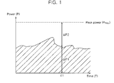
- FIG. 1 is a graph explaining power allocation in a conventional mobile communication system.
- ⁇ P 1 allocated to a mobile station for the line service at a certain time, t 1 , when any mobile station begins to get the packet data service, namely, there is generated new packet data traffic
- the power corresponding to ⁇ P 2 is allocated to the mobile station making use of the packet data service.
- the conventional systems transmit the packet data traffic in such a manner that the power, ⁇ P 1 , of the base transceiver station is preferentially allocated to the line service, and then all the power, ⁇ P 2 , remaining after allocation to the line service is allocated to the new mobile station, which makes use of the packet data service.
- the power, ⁇ P 2 allocated to the mobile station making use of the packet data service forces mobile stations, which make use of the line service while the constant power control is currently performed, to incur tremendous increase in noise.
- this is responsible for allocating all the power remaining after the line service is provided to the mobile stations making use of the packet data service at once, and thus interference to which the mobile stations making use of the line service are subjected is to be increased tremendously.
- the base transceiver station copes with the tremendously increased interference by means of the power control for guaranteeing the quality of the line service.
- the line service is subjected to outage for that time. Consequently, this leads to a problem in that the quality of the line service deteriorates.
- an object of the present invention to provide a power allocation method and apparatus for providing a packet data service in a mobile communication system, capable of reducing line outage service while simultaneously providing the line service and the packet data service in the same frequency allocation.
- a power allocation method for providing a packet data service in a mobile communication system comprising the steps of: (a) checking whether or not packet data traffic to be transmitted is newly generated; (b) if it is checked and the packet data traffic to be transmitted is newly generated in the step (a), checking whether or not there is a mobile station making use of a line service where a current call is in progress; (c) if it is checked and there is the mobile station making use of the line service where the current call is in progress, checking whether or not the packet data traffic is currently transmitted to any other mobile station; and (d) if it is checked and the packet data traffic is not currently transmitted to the other mobile station, allocating power by gradually increasing power transmitted to the mobile station making use of a new packet data service by a preset increment for a preset predetermined time.
- the power allocation apparatus comprises a base transceiver station of a mobile communication network and a control section.
- the base transceiver station includes an antenna for performing wireless communication with a mobile station; a transmission section for performing wireless transmission by means of the antenna; a reception section for performing wireless reception by means of the antenna; a data reception section for receiving data to be transmitted from the mobile communication network to the mobile station; a data processing section for processing the data received through the data reception section in accordance with a predetermined algorithm; a modulation section for modulating the data processed by the data processing section; and a power section for supplying/driving power to allow the data modulated by the modulation section to be transmitted through the antenna.
- the control section checks whether or not there is the mobile station making use of the packet data service, and according to the checked result, controlling the power section to gradually increase the power transmitted to the mobile station making use of the packet data service.
- FIG. 1 is a graph for explaining power allocation in a conventional mobile communication system
- FIGS. 2 a and 2 b are schematic graphs explaining a power allocation method according to the invention.
- FIG. 3 is a schematic view for explaining a configuration of a mobile communication system to which the invention is applied;
- FIG. 4 is a block diagram explaining a configuration of a base transceiver station according to the invention.
- FIG. 5 is a block diagram explaining a configuration of a control section according to the invention.
- FIG. 6 is a flow chart explaining a power control method according to the invention.
- FIG. 7 is a graph explaining an effect according to the invention.
- the invention provides an apparatus and method of power allocation for a packet data service in a mobile communication system, in which, in a situation where at least one voice call (line service) is in progress at a base transceiver station (BTS) with the use of the same frequency allocation (FA) but a packet data call is not yet present, when a new packet data call is generated, power can be allocated when packet data traffic generated by the new packet data call is transmitted.
- BTS base transceiver station
- FA frequency allocation
- the allocation of power is provided as follows.
- a magnitude of the slot is an intrinsic set value of a system to be applied. For instance, this embodiment has the slot of 1.25 msec.
- MS mobile station
- packet data traffic for the MS getting a packet data service is generated at a slot time t and then is transmitted at another slot time t+1.
- the total power available for the MS getting the packet data service may be given as in Equation 1.
- M RC ( t+ 1) P Full ⁇ P OH ⁇ P PC ( t+ 1) Equation 1
- P FULL the peak power available at the BTS
- P OH the power allocated to an overhead channel (control channel)
- P PC (t) the power allocated to MS getting the line service at the slot time t.
- the allocation of power is performed in such a manner that the total power, which is available at the MS getting the packet data service and is expressed by Equation 1, is gradually increased for a preset predetermined period of time, i.e., for n number of slots.
- the interval, which corresponds to n slots while the power allocation is gradually performed, is called a power increase interval.
- the power increase interval n for gradually increasing power may be set in various ways, one of which is as follows.
- T refers to the time covering the range from a time point of transmitting packet data traffic for the first time to a time point at which transmission power for the MS making use of the line service reaches a stable state by means of transmission power control of the BTS, a value (the number of slots) dividing the time T by the magnitude of the slot is set to the power increase interval n for gradually increasing the power.
- an S/N ratio can be defined as a value dividing the product of transmission power P and channel gain G by noise N, i.e., in a form of (P ⁇ G)/N.
- the noise N includes the power supplied to the MS which make use of the packet data service as mentioned above.
- a signal-to-interference ratio (SIR) of the MS i can be represented as in the following Equation 2 (where the interference means a noise).
- G the channel gain
- Equation 3 in the case where the packet data traffic is generated at the MS getting the packet data service at the slot time t and then is transmitted at the slot time t+1 in the state of Equation 2, SIRs of the MSs getting the line service have a value lower than that of a targeted SIR.
- the power control is performed to the MSs making use of the line service where calls are in progress during an n i slot, and the SIR of the power control MS i returns to ⁇ , and thus the transmission power of the BTS is equal to the peak power, P FULL .
- Equation 3 can be expressed as the following Equation 4.
- Equation 4 can be modified like Equation 5.
- n i log ⁇ ⁇ [ 1 + ⁇ ⁇ ⁇ ⁇ 1 + ⁇ ⁇ ⁇ ⁇ ⁇ P Full - P OH - P PC ⁇ ( t ) P i ⁇ ( t ) ] Equation ⁇ ⁇ 5
- i is the parameter indicating a particular mobile station.
- n is the number of slots required until the power of the MS making use of the line service is restored to a normal state.
- the SIR of the MS i i.e. ⁇
- the interference that the power control MS or the MS i gets is increased, so that ⁇ is lowered.
- FIGS. 2 a and 2 b are graphs explaining a power allocation method according to the invention.
- FIG. 2 a shows the method for linearly allocating the power to the packet traffic during the time of n slots in which the power is allocated in such a manner that the power is gradually and uniformly increased at each slot time t, t+1, t+2, t+3, . . . , t+n.
- FIG. 2 b shows the method for exponentially allocating the power to the packet traffic during the time of n slots in which the power is allocated in such a manner that the power is gradually increased at each slot time t, t+1, t+2, t+3, . . . , t+n so as to converge at a constant value according to an exponential function.
- SPI sudden power increase
- the LGPI as well as the EGPI can be given as in Equation 7.
- the SPI is to represent a numerical formula according to the conventional power allocation method.
- P RC ⁇ ( t + k ) ⁇ SPI ⁇ : ⁇ ⁇ M RC ⁇ ( t + k ) LGPI ⁇ : ⁇ ⁇ M RC ⁇ ( t + k ) ⁇ min ⁇ [ k n + 1 , 1 ] EGPI ⁇ : ⁇ ⁇ M RC ⁇ ( t + k ) ⁇ ( 1 - q k ) Equation ⁇ ⁇ 7
- M RC (t) the peak power available for the MS getting the packet data service
- n the power increase interval (the number of slots), and the integer satisfying n ⁇ 1,
- k the number of times of the slots by which the power increase is performed, and the integer satisfying 1 ⁇ k ⁇ n,
- Equation 7 is applied to the LGPI such as the graph shown in FIG. 2 a , as set forth above, the transmission power is expressed as follows:
- the power transmitted to the MS making use of the packet data service at each slot time t, t+1, t+2, t+3, . . . , t+n can be calculated.
- Equation 7 the power can be allocated like the graph shown in FIG. 2 b.
- FIG. 3 is a schematic view explaining the configuration of a mobile communication system to which the invention is applied.
- a mobile communication network includes a base transceiver station (BTS) 100 for performing wireless communication with at least one mobile station (MS) 10 , a base station controller (BSC) 200 connected to a mobile switching center (MSC) 300 and for controlling the BTS 100 , and a packet data service node (PDSN) 400 connected to the BSC 200 to provide a packet data service and connected to a data core network (DCN) 500 .
- BTS base transceiver station
- MSC mobile switching center
- PDSN packet data service node
- a configuration of the BTS will be described below with reference to FIG. 4 .
- the BTS 100 includes an antenna 110 for performing wireless communication with at least one MS 10 , a transmission section 121 for performing wireless transmission by means of the antenna 110 , a reception section 122 for performing wireless reception by means of the antenna 110 , a data reception section 150 for receiving data to be transmitted from a mobile communication network to the MS 10 , a data processing section 140 for processing the data received through the data reception section 150 in accordance with a predetermined algorithm, a modulation section 130 for modulating the data processed by the data processing section 140 , a power section 160 for supplying/driving power to allow the transmission section 121 to transmit the data modulated by the modulation section 130 through the antenna 110 , and a control section 170 for controlling the power section 160 to perform power allocation (e.g. EGPI or LGPI).
- power allocation e.g. EGPI or LGPI
- control section 170 is incorporated in the BTS 100 , but it may be either built in the BSC 200 or provided as a separate device.
- FIG. 5 is a block diagram explaining a configuration of the control section according to the invention.
- the control section 170 includes a packet scheduler 171 for receiving data transmitted from a mobile communication network to perform packet scheduling, a channel estimator 172 for estimating channels according to signals received through the reception section 122 , a channel allocator 173 for allocating communication channels, a power allocator 174 for controlling the power section 160 to allocate transmission power, and a coding and modulating selector 175 for performing coding and modulating of the data.
- a packet scheduler 171 for receiving data transmitted from a mobile communication network to perform packet scheduling
- a channel estimator 172 for estimating channels according to signals received through the reception section 122
- a channel allocator 173 for allocating communication channels
- a power allocator 174 for controlling the power section 160 to allocate transmission power
- a coding and modulating selector 175 for performing coding and modulating of the data.
- FIG. 6 is a flow chart for explaining power allocation according to the invention.
- the control section 170 checks whether or not packet data traffic is generated (S 100 ). As the checked result, if the packet data traffic is not generated in the step S 100 , the power allocation procedure is performed again from the start of the flow chart at the next slot.
- the control section 170 checks whether or not there is at least one MS making use of a line service (voice call) where a call is currently in progress (S 200 ).
- the control section determines whether or not packet data are transmitted at a current slot (S 300 ).
- the control section performs the power allocation to the MS making use of the packet data service with the use of the general power allocation method (SPI) (S 500 ).
- SPI general power allocation method
- the power allocation method according to the invention (S 400 ).
- the power allocation method in the step S 400 follows Equation 7.
- the step S 400 is performed.
- the power allocation is performed in such a way that the power transmitted to the MS making use of the packet data service is linearly or exponentially increased step by step, so that it is possible to minimize outage information of the MS making use of the line service (voice call).
- the MSs are uniformly distributed in the omni-cell. Each MS moves at an average speed of 3 km/h with a standard deviation of 1 km/h. Further, each MS has a probability ratio of 30% to 70%, where 30% is the probability of changing a motion direction every five seconds and 70% is the probability of not doing so.
- the omni-cell is a hexagonal cell where each side is 300 meters. Seven cells are provided to have a wrapped around structure.
- the power control method for the voice call of the MSs which make use of the line service during a simulation follows a Radio Configuration 3 for CDMA2000-1X which is proposed by 3GPP2.
- the number of MSs making use of the line service is ten (10), and the number of MSs making use of the packet data service is variable, for example from 10 to 60. As the number of the MSs making use of the packet data service was increased, the resultant change was observed.
- As a main performance index outage of the MSs making use of the line service (voice call) was used, where the outage was defined to be generated when reception Eb/No of the MS is below a reference value at each slot. For the simulation, the reference value was set to 5 dB.
- an outage probability indicating outage information on the MSs making use of the line service is lowered as the number of MSs making use of the packet data service is increased more and more.
- the power allocation method (EGPI or LGPI) according to the invention is remarkably low comparing with the conventional power allocation method (SPI).
- the invention of providing the apparatus and method of power allocation for the packet data service in mobile communication systems, by gradually increasing the power, which is transmitted to MSs making use of the packet data service at a preset period of time for a preset predetermined period of time, the line service and the packet data service can be simultaneously provided, and the outage of the MSs making use of the line service can be remarkably reduced compared with the conventional method.
Abstract
Description
M RC(t+1)=P Full −P OH −P PC(t+1)
n=def┌navg┐ Equation 6
Claims (22)
Applications Claiming Priority (2)
| Application Number | Priority Date | Filing Date | Title |
|---|---|---|---|
| KR10-2003-0038063A KR100519666B1 (en) | 2003-06-12 | 2003-06-12 | Power Allocation Apparatus and Method for Packet Data Services in Mobile Communications Systems |
| KR10-2003-0038063 | 2003-06-12 |
Publications (2)
| Publication Number | Publication Date |
|---|---|
| US20040253928A1 US20040253928A1 (en) | 2004-12-16 |
| US7558231B2 true US7558231B2 (en) | 2009-07-07 |
Family
ID=33509690
Family Applications (1)
| Application Number | Title | Priority Date | Filing Date |
|---|---|---|---|
| US10/758,028 Expired - Fee Related US7558231B2 (en) | 2003-06-12 | 2004-01-14 | Power allocation method and apparatus for providing packet data service in mobile communication system |
Country Status (3)
| Country | Link |
|---|---|
| US (1) | US7558231B2 (en) |
| JP (1) | JP4565444B2 (en) |
| KR (1) | KR100519666B1 (en) |
Families Citing this family (6)
| Publication number | Priority date | Publication date | Assignee | Title |
|---|---|---|---|---|
| US8320951B2 (en) * | 2004-03-12 | 2012-11-27 | Alcatel Lucent | Power sharing process in cellular network architecture |
| US7756543B2 (en) * | 2005-09-09 | 2010-07-13 | Telefonaktiebolaget Lm Ericsson (Publ) | High speed shared radio channel transmit power control |
| US20070121535A1 (en) * | 2005-09-30 | 2007-05-31 | Wanshi Chen | Dynamic transmit power for non-canonical transmission formats |
| KR100962115B1 (en) | 2007-07-06 | 2010-06-10 | 삼성전자주식회사 | Method and apparatus for jointly controlling transmitt power in congitive radio communication system |
| JP5169689B2 (en) * | 2008-02-14 | 2013-03-27 | 富士通株式会社 | Communication device |
| CN102144664B (en) * | 2010-12-27 | 2012-10-17 | 山东营养源食品科技有限公司 | Solid hydrogen peroxide sustained release preparation and preparation method thereof |
Citations (6)
| Publication number | Priority date | Publication date | Assignee | Title |
|---|---|---|---|---|
| US5175867A (en) * | 1991-03-15 | 1992-12-29 | Telefonaktiebolaget L M Ericsson | Neighbor-assisted handoff in a cellular communications system |
| US5745523A (en) * | 1992-10-27 | 1998-04-28 | Ericsson Inc. | Multi-mode signal processing |
| US5982760A (en) * | 1997-06-20 | 1999-11-09 | Qualcomm Inc. | Method and apparatus for power adaptation control in closed-loop communications |
| US6374117B1 (en) * | 1999-12-22 | 2002-04-16 | Telefonaktiebolaget Lm Ericsson (Publ) | Queue based power control scheduling |
| US6950669B2 (en) * | 2000-07-05 | 2005-09-27 | Telefonaktiebolaget Lm Ericsson (Publ) | Power control algorithm for packet data based on queue/channel utilization |
| US7209724B2 (en) * | 1999-06-14 | 2007-04-24 | Alereon, Inc. | Method and apparatus for power control in an ultra wideband radio system |
Family Cites Families (3)
| Publication number | Priority date | Publication date | Assignee | Title |
|---|---|---|---|---|
| JPH07283783A (en) * | 1994-04-12 | 1995-10-27 | Matsushita Electric Ind Co Ltd | Radio communication system |
| JP2000091985A (en) * | 1998-09-08 | 2000-03-31 | Hitachi Ltd | Power control method for communication system |
| JP3535427B2 (en) * | 1999-11-25 | 2004-06-07 | 松下電器産業株式会社 | Wireless communication device |
-
2003
- 2003-06-12 KR KR10-2003-0038063A patent/KR100519666B1/en active IP Right Grant
-
2004
- 2004-01-14 US US10/758,028 patent/US7558231B2/en not_active Expired - Fee Related
- 2004-01-27 JP JP2004018704A patent/JP4565444B2/en not_active Expired - Fee Related
Patent Citations (6)
| Publication number | Priority date | Publication date | Assignee | Title |
|---|---|---|---|---|
| US5175867A (en) * | 1991-03-15 | 1992-12-29 | Telefonaktiebolaget L M Ericsson | Neighbor-assisted handoff in a cellular communications system |
| US5745523A (en) * | 1992-10-27 | 1998-04-28 | Ericsson Inc. | Multi-mode signal processing |
| US5982760A (en) * | 1997-06-20 | 1999-11-09 | Qualcomm Inc. | Method and apparatus for power adaptation control in closed-loop communications |
| US7209724B2 (en) * | 1999-06-14 | 2007-04-24 | Alereon, Inc. | Method and apparatus for power control in an ultra wideband radio system |
| US6374117B1 (en) * | 1999-12-22 | 2002-04-16 | Telefonaktiebolaget Lm Ericsson (Publ) | Queue based power control scheduling |
| US6950669B2 (en) * | 2000-07-05 | 2005-09-27 | Telefonaktiebolaget Lm Ericsson (Publ) | Power control algorithm for packet data based on queue/channel utilization |
Non-Patent Citations (3)
| Title |
|---|
| Insoo Koo, Jeongrok Yang, Yeongyoon Choi and Kiseon Kim, "Capacity-Optimized Power Allocation Scheme in an Integrated Voice and Data DS-CDMA System", Sep. 15, 1999, IEEE, TENCON 99. Proceedings of the IEEE Region 10 Conference, pp. 1178-1181 vol. 2. * |
| Lay Teen Ong and Sangarapillai Lambotharan, "Variable Rate Variable Power Mimo System for Integrated Voice and Data Services", Oct. 2006, IEEE, 10th IEEE Singapore International Conference on Communication systems, 2006. ICCS 2006, pp. 1-5. * |
| Qiang Shen, "Power Assignment in CDMA Personal Communication Systems With Integrated Voice/Data Traffic", Nov. 18, 1996, IEEE, Global Telecommunications Conference, 1996. GLOBECOM '96, pp. 168-172. * |
Also Published As
| Publication number | Publication date |
|---|---|
| KR100519666B1 (en) | 2005-10-07 |
| KR20040107163A (en) | 2004-12-20 |
| JP4565444B2 (en) | 2010-10-20 |
| JP2005006278A (en) | 2005-01-06 |
| US20040253928A1 (en) | 2004-12-16 |
Similar Documents
| Publication | Publication Date | Title |
|---|---|---|
| US9832735B2 (en) | Uplink power control using received power control information | |
| EP1729533A1 (en) | Scheduling method in a radio communication system using relay stations, and system therefor | |
| US8228793B2 (en) | Method for adaptive delay threshold-based priority queueing scheme for packet scheduling in mobile broadband wireless access system | |
| AU2002259200A1 (en) | Common control channel uplink power control for adaptive modulation and coding techniques | |
| EP1807943B1 (en) | Radio quality based channel resource management | |
| US20070105593A1 (en) | Equalizing signal-to-interference ratios of different physical channels supporting a coded composite transport channel | |
| US7558231B2 (en) | Power allocation method and apparatus for providing packet data service in mobile communication system | |
| US20040058685A1 (en) | Allocation of shared channel data rates in a communication system | |
| US7342911B2 (en) | Network element and a method for traffic management | |
| WO2004102899A1 (en) | A traffic management method that divides time slots into sub-blocks for real time and non-real time traffic |
Legal Events
| Date | Code | Title | Description |
|---|---|---|---|
| AS | Assignment |
Owner name: JEONG, DONG GEUN, KOREA, REPUBLIC OF Free format text: ASSIGNMENT OF ASSIGNORS INTEREST;ASSIGNORS:JEON, WHA SOOK;JEONG, DONG GEUN;CHUNG, WON SUK;AND OTHERS;REEL/FRAME:015066/0846;SIGNING DATES FROM 20040720 TO 20040729 Owner name: SK TELECOM CO., LTD., KOREA, REPUBLIC OF Free format text: ASSIGNMENT OF ASSIGNORS INTEREST;ASSIGNORS:JEON, WHA SOOK;JEONG, DONG GEUN;CHUNG, WON SUK;AND OTHERS;REEL/FRAME:015066/0837;SIGNING DATES FROM 20040720 TO 20040729 |
|
| STCF | Information on status: patent grant |
Free format text: PATENTED CASE |
|
| FPAY | Fee payment |
Year of fee payment: 4 |
|
| FPAY | Fee payment |
Year of fee payment: 8 |
|
| FEPP | Fee payment procedure |
Free format text: MAINTENANCE FEE REMINDER MAILED (ORIGINAL EVENT CODE: REM.); ENTITY STATUS OF PATENT OWNER: LARGE ENTITY |
|
| LAPS | Lapse for failure to pay maintenance fees |
Free format text: PATENT EXPIRED FOR FAILURE TO PAY MAINTENANCE FEES (ORIGINAL EVENT CODE: EXP.); ENTITY STATUS OF PATENT OWNER: LARGE ENTITY |
|
| STCH | Information on status: patent discontinuation |
Free format text: PATENT EXPIRED DUE TO NONPAYMENT OF MAINTENANCE FEES UNDER 37 CFR 1.362 |
|
| FP | Lapsed due to failure to pay maintenance fee |
Effective date: 20210707 |