US7570213B2 - Method and apparatus for detecting and locating intrusion in a wireless network - Google Patents
Method and apparatus for detecting and locating intrusion in a wireless network Download PDFInfo
- Publication number
- US7570213B2 US7570213B2 US11/449,184 US44918406A US7570213B2 US 7570213 B2 US7570213 B2 US 7570213B2 US 44918406 A US44918406 A US 44918406A US 7570213 B2 US7570213 B2 US 7570213B2
- Authority
- US
- United States
- Prior art keywords
- computing
- intersection
- point
- locus
- points
- Prior art date
- Legal status (The legal status is an assumption and is not a legal conclusion. Google has not performed a legal analysis and makes no representation as to the accuracy of the status listed.)
- Active, expires
Links
Images


Classifications
-
- G—PHYSICS
- G01—MEASURING; TESTING
- G01S—RADIO DIRECTION-FINDING; RADIO NAVIGATION; DETERMINING DISTANCE OR VELOCITY BY USE OF RADIO WAVES; LOCATING OR PRESENCE-DETECTING BY USE OF THE REFLECTION OR RERADIATION OF RADIO WAVES; ANALOGOUS ARRANGEMENTS USING OTHER WAVES
- G01S5/00—Position-fixing by co-ordinating two or more direction or position line determinations; Position-fixing by co-ordinating two or more distance determinations
- G01S5/02—Position-fixing by co-ordinating two or more direction or position line determinations; Position-fixing by co-ordinating two or more distance determinations using radio waves
- G01S5/14—Determining absolute distances from a plurality of spaced points of known location
Definitions
- This invention relates generally to the field of location of radio frequency transmitters. This invention relates more specifically to the algorithms and processing techniques applied thereto for the location of rogue radio frequency transmitters based upon multiple measures of received signal strength.
- U.S. Pat. No. 7,006,838 B2 to Diener et al discloses an apparatus and method for determining the location of an unknown wireless radio signal source.
- the unknown source's signal is received at a plurality of known receiving locations where one of the plurality is used as a reference.
- the source's signals received at all other receiving locations are compared to the reference.
- a reference signal is transmitted by a known location whereupon the difference of time of arrival between the known reference signal and the unknown source's signal is computed and the location of the unknown source computed therefrom.
- This system has the disadvantage, however, in that it is not passively listening to an intruding source, rather it must actively transmit a reference signal having the effect of making its presence known.
- U.S. Pat. No. 6,993,592 B2 to Krumm et al discloses a location measurement apparatus and process for determining the location of radio-frequency badges where the badges transmit a message containing their unique identifier to receivers at known locations.
- the receivers measure signal strength of the transmitting badge if it exceeds a predefined threshold.
- the receivers then transmit data to a central computer as to the time, identification and received signal strength indication (RSSI) for each badge, which is entered into a table. Locations are computed for those badges whose signal strength exceeds the predefined threshold.
- RSSI received signal strength indication
- U.S. Pat. No. 6,920,329 B2 to Kennedy, Jr. et al discloses an apparatus and method to find the location of two-way radios amongst a plurality of base stations at known geographic points.
- the invention employs a time of arrival determination which may also be combined with an angle of arrival determination.
- antenna characteristics of the receiving base stations is critical, as well as is their orientation, meaning the system must be well calibrated. This would further suggest that the system has no utility for other than a permanently fixed deployment.
- U.S. Pat. No. 6,861,982 B2 to Forstrom et al discloses a method for determining the location of a non-cooperative radio frequency emitter requiring at least three receivers sharing common time with a time reference. Trilateration is employed on signal detection times from emitter to receivers. Since any or all of the receivers may be mobile, communication with the reference provides an accurate adjustment of propagation time in compensation for the receiver's mobility. Since trilateration is employed, this system will have no utility with fewer than three receivers deployed, operating, and in reception of the signal source.
- U.S. Pat. No. 7,020,475 B2 to Bahl et al discloses a method for a mobile computer user to determine his location within a building.
- Wireless base stations are employed at known locations throughout a building. Signal strength is measured and looked up in a table of known locations of base stations and their respective signal strengths. The current location of the mobile computer user is determined as the one corresponding to the most likely base station.
- the method may be used in the opposite sense where the base stations detect the signal strength of the mobile computer user, provided a reference signal strength versus distance of the mobile computer from the base stations is known.
- This system depends entirely upon charted signal strengths at predetermined locations within a fixed structure. It would have little utility for geolocating a wider ranging intruder signal source of unknown signal strength.
- U.S. Pat. No. 7,019,694 B2 to Krumm et al discloses a method for locating radio frequency transmitters.
- a plurality of receivers measure and forward signal strength to a central computer. Multiple measured signal strengths attributed to the same transmitter form a locating signal strength vector.
- Exemplary vectors are generated in a calibration procedure to various locations. The locating signal strength vector is compared to the previously obtained exemplary vectors to determine with which exemplary vector the locating signal strength vector corresponds, so as to determine the location of the radio frequency transmitter.
- the benefits of this system include reception by as few as only one receiver and compatibility with an existing computer network.
- the drawback of this system is that it is possible to locate a signal source only if receivers are already placed in, and the network to which they are connected is extended to, every conceivable location a signal source of interest might be.
- Angle of Arrival (AoA) and Time Difference of Arrival (TDOA) methods are desirable to use, but they require directional antennas that must be precisely sited and/or complex receiver hardware with additional channel capacity for distributing precise time references. Aside from the time it would take to integrate, calibrate and maintain these components, their addition greatly increases the cost of a wireless intrusion detection system (WIDS).
- WIDS wireless intrusion detection system
- the present invention performs location solely on the non-directional Received Signal Strength Indication (RSSI) provided by the commercial off-the-shelf (COTS) wireless cards.
- RSSI Received Signal Strength Indication
- COTS commercial off-the-shelf
- the mathematical analysis can be limited to two dimensions.
- a two-dimensional analysis is suitable for a drive-by network intruder scenario, for example, it is clearly inadequate for three-dimensional structures such as multi-floor office buildings.
- Rogue network intruders must transmit There is no way for a WIDS receiver to detect a purely passive monitor. WIDS sightings must be simultaneous to detect a mobile rogue transmitter. Stationary transmitters, which transmit periodically, can be located by integrating measurements obtained over a period of time.
- the present invention provides a method and apparatus for detecting the presence of and locating the source of a radio frequency signal.
- An additional object of the present invention is to provide a method and apparatus for detecting and locating the source of an intruding signal without dependence upon time synchronization between receivers.
- An additional object of the present invention is to provide a method and apparatus for detecting and locating the source of an intruding signal without being limited to locating such sources only within a pre-calibrated geospace.
- the present invention method and apparatus for detecting and locating intrusion in a wireless network, achieves these and other objects through computing relative distance measurements between pairs from a plurality of receivers to the source of the intruding signal based on received signal strength and through determining the loci of possible locations, by plotting the loci, by finding the points of intersection of these loci and by applying a clustering algorithm thereto from which the actual location of the source of the intruding signal is found.
- the present invention is distinguished from the prior art in that its operation does not rely upon knowledge of either the transmitted power or antenna gain of the intruding signal source.
- an intruding radio frequency signal is first received by a plurality of receivers.
- the received signal strength R i is then measured on each of the plurality of receivers.
- one relative distance measurement d to the location of the transmitting source is computed, where the one relative distance measurement d is a function of the received signal strength R i of each of the receivers in each of the paired combinations.
- the computation further comprises computing the displacement c of the center of the locus from the first receiver in each paired combination according to
- x c x 1 + c D ⁇ ⁇ ( x 2 - x 1 ) and
- the intermediate points of intersection of all loci corresponding to all paired combinations are then computed.
- the actual points of intersection from the intermediate points of intersection of all the loci of points are computed so as to determine an unambiguous location of the transmitting source.
- the number of possible loci on which an intruding radio frequency signal source may be located is determined as M, where
- method for detecting and locating a transmitting source of a radio frequency (RF) signal intrusion into a wireless network the number of possible points at which the loci intersect and at which an intruding radio frequency signal source may be further deemed to be located is determined as I, where
- N the number of receivers in reception of the intruding signal
- M the number of possible loci of points on which an intruding radio frequency signal source may be located.
- the present invention may be rapidly deployed to an unsurveyed and uncalibrated location and commence locating a radio frequency source. This is a fundamental need which has yet been unfulfilled in the prior art.
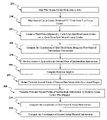
- FIG. 1 a and FIG. 1 b depict the distance measurement based on WIDS RSSI and the steps to accomplish the same. “Best straight line” from linear regression is shown.
- FIG. 2 and FIG. 2 b depict two WIDS receivers sighting a rogue transmitter (denoted by “Tx”) and the steps to accomplish plotting loci based on relative distance measurements. Relative distances are 3 and 5 units.
- FIG. 6 depicts three sightings resulting in two possible solutions for target transmitter.
- FIG. 7 depicts another configuration with three sightings that result in two possible solutions for target transmitter.
- FIG. 8 depicts that adding a fourth WIDS sighting to the configuration shown in FIG. 6 results in a single solution for target location. See blow-up of area of interest.
- FIG. 9 depicts that adding a fourth WIDS sighting to the configuration shown in FIG. 7 results in a single solution for target location. See blow-up of area of interest.
- FIG. 10 depicts how collinear placement of four WIDS receivers results in two possible solutions.
- FIG. 11 a and FIG. 11 b depict the distance and angle relationship between two circle center points P 1 and P 2 and the steps to compute the Euclidean distance therebetween.
- the circles have radii r 1 and r 2 , respectively (not shown).
- FIG. 12 a and FIG. 12 b depict the translation and rotation of the two circle center points P 1 and P 2 to new points P′ 1 and P′ 2 .
- Point P′ 3 is at distance r 1 from P′ 1 and distance r 2 from P′ 2 and the steps to accomplish the same. (Second point P′ 4 that satisfies this condition is not shown.)
- FIG. 13 a and FIG. 13 b depict four WIDS sighting resulting in a single solution for target location and the steps to determine the number of possible loci and intersections given the number of WIDS receivers.
- FIG. 14 depicts the elements of the present invention deployed so as to protect a network from intrusion by intruding signal sources at wireless access points.
- FIG. 15 depicts subcomponents of an exemplary wireless intrusion detection sensor embodiment of the present invention.
- FIG. 16 depicts a physical deployment of a plurality of wireless intrusion detection processors in a building environment.
- RSSI Received Signal Strength Indication
- the first step thereafter is to convert measured RSSI to some measure of the distance 110 from a WIDS receiver to the rogue transmitter.
- GPS Global Positional Service
- GPS in the 3-D world finds the intersection of spheres—there are two solutions with three spheres but one is discarded as being too far from the Earth's surface. While technically. GPS trilaterates, in fact GPS needs at least one or more additional satellites in view to compensate for timing errors that result in distance errors. Time is thus considered to be a fourth dimension. In the present invention the term multilateration is used instead of trilateration, as usually more than three distances are measured.
- the present invention performs at best a relative distance measurement.
- FIG. 1 a and FIG. 1 b depict the results of experiments performed to determine what the RSSI actually measures and to relate that value to an indication of distance. It can be seen that:
- FIG. 2 a and FIG. 2 b the result achieved when two WIDS receivers in the present invention are used to make a pair of relative distance measurements 160 to a rogue transmitter, is depicted.
- d 1 and d 2 represent the estimated distances from a rogue transmitter to WIDS receiver # 1 and WIDS receiver # 2 , respectively, where the scale of the distance measurement is assumed to be linear with zero offset, but otherwise unknown.
- the location of WIDS receiver # 1 is denoted as (x 1 , y 1 ) and the location of WIDS receiver # 2 is denoted as (x 2 , y 2 ).
- the circle is not centered on a WIDS receiver. Rather, it is centered at some displacement, c, from WIDS receiver # 1 along a line joining the two WIDS receivers.
- the value of c is computed 190 as
- x c x 1 + c D ⁇ ⁇ ( x 2 - x 1 )
- y c y 1 + c D ⁇ ( y 2 - y 1 )
- WIDS receiver # 1 is at (0, 0)
- WIDS receiver # 2 is at (4, 0)
- the (usually unknown) position of the rogue transmitter is (0, 3).
- the rogue transmitters are denoted as “Tx” in FIG. 2 a .
- FIG. 3 shows the circle resulting from the equations for (x c , y c ) and r, which clearly contains the point (0, 3) where the rogue transmitter is located.
- FIG. 4 shows the result when the relative distances are the same as in the previous example, but the relationship is reversed, i.e., the rogue transmitter is closer to WIDS receiver # 2 .
- FIG. 6 and FIG. 7 depicts the problem with only three sightings being that there are two possible locations of the rogue transmitter.
- FIG. 10 it is shown that notwithstanding four sightings, it is critical to ensure that collinear placement of WIDS receivers is avoided, because if the four WIDS receivers lie on a straight line two solutions are obtained rather than the unambiguous unique solution. Having three collinear WIDS receivers in the present invention is acceptable. The problem arises when there are four collinear receivers.
- P 4 ( x 4 ,y 4 )
- L 1 and h can be solved for because from the Law of Cosines it can be shown that
- the two solutions, P′ 3 and P′ 4 are based on the two center points P′ 1 and P′ 2 that were mapped on to the x-axis. It remains to rotate and translate these two values to obtain the actual solutions for the intersections: P 3 and P 4 .
- Circle center P 1 was mapped specifically to point P′ 1 at the origin to facilitate the rotation and translation operations. This must now be accounted for to find the actual points of intersection. Letting a denote the counterclockwise angle that P 2 makes with P 1 with respect to the x-axis (see FIG. 11 a ). Then the sin and cosine of ⁇ are computed 280 as
- each pair of WIDS sightings yields one relative distance estimate, which yields one circle (specified as a center point P and radius r).
- Each pair of these resulting circles yields a pair of intersections, P 3 and P 4 .
- a minimum of four non-collinear WIDS sightings are required to obtain a unique solution.
- N represents the number of WIDS receivers that have sighted a rogue transmitter
- M represents the number of circles that result
- I represents the number of intersections. Therefore, since each pair of WIDS receivers create a circle, the number of resulting locus circles is computed 330 as
- the present invention will not generally yield fourth order or higher expressions for I since the number of receivers N is limited to those that simultaneously determine a RSSI for a given rogue transmitter.
- the elements of the present invention comprising the plurality of wireless intrusion detection processors, the enterprise security management (ESM) processor and the wireless intrusion detection concentrator processor are depicted deployed so as to detect intrusion by signal sources, either standalone, or those that are transmitting into wireless access points.
- ESM enterprise security management
- FIG. 15 photographically shows the subcomponents of an exemplary wireless intrusion detection sensor embodiment.
- FIG. 16 a deployment of wireless intrusion detection processor of the present invention is shown in a building.
- Hewlett Packard OpenView® software is utilized in the enterprise security management (ESM) processor to log all intrusion events by time, location, signal strength and severity.
- ESM enterprise security management
Abstract
Description
where D is the distance between the receivers in each paired combination. The radius r of the locus is computed according to
and the coordinates (xc, yc) of the point about which the locus is centered satisfying
and
computed, where (x1,y1) and (x2,y2) are the coordinates of the first and the second receivers in each paired combination, respectively. The intermediate points of intersection of all loci corresponding to all paired combinations are then computed. Finally, the actual points of intersection from the intermediate points of intersection of all the loci of points are computed so as to determine an unambiguous location of the transmitting source.
and where N is the number of receivers in reception of the intruding signal.
where N is the number of receivers in reception of the intruding signal and M is the number of possible loci of points on which an intruding radio frequency signal source may be located.
- [Aldu04] R. Aldunate, M. Nussbaum, and F. Pena-Mora, “An Empirical Wi-Fi Based Location Mechanism for Urban Search and Rescue Operations,” in Proceedings, Wired/Wireless Internet Communications, 2nd International Conference (WWIC 2004), Berlin: Springer-Verlag, 2004.
- [Eng04] P. Enge, “Retooling the Global Positioning System,” Scientific American, May 2004, pp. 90-95.
[Li02] D. Li, K. D. Wong, Y. H. Hu, and A. M. Sayeed, “Detection, Classification, and Tracking of Targets,” IEEE Signal Processing Magazine, March 2002, pp. 17-29. - [Men73] W. Mendenhall and R. L. Scheaffer, Mathematical Statistics with Applications, North Scituate Mass.: Duxbury Press, 1973.
- [Per03] P. E. Pertilä, T. W. Pirinen, A. J. Visa, and T. S. Korhonen, “Comparison of Three Post-Processing Methods for Acoustic Localization,” Proceedings, Unattended Ground Sensor Technologies and Applications V-5090, SPIE AeroSense, 2003.
- [Smi98] A. A. Smith Jr., Radio Frequency Principles and Applications, Piscataway N.J.: IEEE Press, 1998.
- [Spi68] M. R. Spiegel, Mathematical Handbook, NY: McGraw-Hill Book Company, 1968.
- [Stra97] G. Strang and K. Borre, Linear Algebra, Geodesy, and GPS, Wellesley Mass.: Wellesley-Cambridge Press, 1997.
- [Tou74] J. T. Tou and R. C. Gonzalez, Pattern Recognition Principles, Reading Mass.: Addison-Wesley Publishing Company, 1974.
-
- a. The RSSI varies roughly linearly with distance, showing that it measures energy (which falls off as 1/distance) rather than power (which falls off as 1/distance2 or inverse-square law) [Smi98, p. 45];
- b. A simple linear regression provides a best-fit straight line that is “reasonable fit” to the data. This is significant considering the fact that the data were collected at various distances, orientations, and directions, and also propagated through combinations of free space, cinder block, and framed walls;
- c. The linear regression for these data yields a “y=mx+b” form of
distance=−0.03655(RSSI)+4.4648 - d. Due to the fact that other sets of experiments yielded slightly different m and b coefficients it is recommended that each newly installed WIDS receiver in the present invention be “trained” by gathering a set of RSSIs. The linear regression can in part account for the specific RF environment for that sensor.
and
and the y-intercept (or, in this case, the distance axis intercept) is computed 150 as
b=
and the radius of the locus circle is computed 200 as
The coordinates of the center of the locus circle are the point P=(xc, yc), whose coordinates are computed 210 as
Circle 1: Center point P 1=(x c1 ,y c1), radius r 1
Circle 2: Center point P 2=(x c2 ,y c2), radius r 2
their two points of intersection is obtained:
P 3=(x 3 ,y 3) P4=(x 4 ,y 4)
L=√{square root over ((x c2 −x c1)2+(y c2 −y c1)2)}{square root over ((x c2 −x c1)2+(y c2 −y c1)2)},
Intermediate Points of Intersection
Therefore L1 and h, the coordinates of P′3 are computed 260 as
L 1 =r 1 cos θh=r 1 sin θ
It is necessary first to rotate 290 P′3 and P′4 with respect to P′1 by angle α, and then to translate 300 by the displacement of P′1 from P1. These two operations can be accomplished in a single step [Spi68, p. 36] to compute the
x 3 =L 1 cos α−h sin α+x c1
y 3 =h cos α+L 1 sin α+y c1
The coordinates of the other point of intersection, P4=(x4,y4) are similarly computed 320 from P′4=(L1,−h).
and since each pair of circles have two intersections, the number of intersections between locus circles is computed 340 as
Claims (33)
d=[R 1 /R 2]1/2;
L=√{square root over ((x c2 −x c1)2+(y c2 −y c1)2)}{square root over ((x c2 −x c1)2+(y c2 −y c1)2)}
L 1 =r 1 cos θ−.
h=r1 sin θ.
x 3 =L 1 cos α−h sin α+x c1
y 3 =h cos α+L 1 sin α+y c1
x 4 =L 1 cos α−h sin α+x c1
y 4 =h cos α+L 1 sin α+y c1
d=[R 1 /R 2]1/2;
L=√{square root over ((x c2 −x c1)2+(y c2 −y c1)2)}{square root over ((x c2 −x c1)2+(y c2 −y c1)2)}
L1=r1 cos θ.
h=r1 sin θ.
x 3 =L 1 cos α−h sin α+x c1
y 3 =h cos α+L 1 sin α+y c1
x 4 =L 1 cos α−h sin α+x c1
y 4 =h cos α+L 1 sin α+y c1
d=[R 1 /R 2]1/2
Priority Applications (1)
| Application Number | Priority Date | Filing Date | Title |
|---|---|---|---|
| US11/449,184 US7570213B2 (en) | 2005-06-14 | 2006-06-06 | Method and apparatus for detecting and locating intrusion in a wireless network |
Applications Claiming Priority (2)
| Application Number | Priority Date | Filing Date | Title |
|---|---|---|---|
| US69054005P | 2005-06-14 | 2005-06-14 | |
| US11/449,184 US7570213B2 (en) | 2005-06-14 | 2006-06-06 | Method and apparatus for detecting and locating intrusion in a wireless network |
Publications (2)
| Publication Number | Publication Date |
|---|---|
| US20060281473A1 US20060281473A1 (en) | 2006-12-14 |
| US7570213B2 true US7570213B2 (en) | 2009-08-04 |
Family
ID=37524698
Family Applications (1)
| Application Number | Title | Priority Date | Filing Date |
|---|---|---|---|
| US11/449,184 Active 2028-04-08 US7570213B2 (en) | 2005-06-14 | 2006-06-06 | Method and apparatus for detecting and locating intrusion in a wireless network |
Country Status (1)
| Country | Link |
|---|---|
| US (1) | US7570213B2 (en) |
Cited By (4)
| Publication number | Priority date | Publication date | Assignee | Title |
|---|---|---|---|---|
| US20110227747A1 (en) * | 2010-03-19 | 2011-09-22 | Wirefree Corporation | Collision avoidance |
| US20150221193A1 (en) * | 2014-02-04 | 2015-08-06 | Aruba Networks, Inc. | Intrusion Detection and Video Surveillance Activation and Processing |
| US9336302B1 (en) | 2012-07-20 | 2016-05-10 | Zuci Realty Llc | Insight and algorithmic clustering for automated synthesis |
| US11205103B2 (en) | 2016-12-09 | 2021-12-21 | The Research Foundation for the State University | Semisupervised autoencoder for sentiment analysis |
Families Citing this family (12)
| Publication number | Priority date | Publication date | Assignee | Title |
|---|---|---|---|---|
| US8660526B1 (en) * | 2005-06-24 | 2014-02-25 | Rockwell Collins, Inc. | Location-based intrusion detection system |
| US20080094278A1 (en) * | 2006-10-19 | 2008-04-24 | International Business Machines Corporation | Method and system for distance estimation |
| CN102253365B (en) * | 2011-04-22 | 2013-04-24 | 华中科技大学 | Indoor positioning method based on estimation of wireless signal source parameters |
| US9264447B2 (en) * | 2011-09-23 | 2016-02-16 | Arturo Geigel | Simultaneous determination of a mobile device and its user identification |
| US8769688B2 (en) * | 2011-09-23 | 2014-07-01 | Universidad Politécnica de P.R. | Simultaneous determination of a computer location and user identification |
| US9723588B1 (en) * | 2016-03-28 | 2017-08-01 | Google Inc. | Determining a location of a wireless transmitter |
| CN108828643B (en) * | 2018-04-25 | 2022-04-29 | 长安大学 | Indoor and outdoor seamless positioning system and method based on grey prediction model |
| US11665663B2 (en) | 2020-07-29 | 2023-05-30 | Entotem Limited | Transmitting data over a radio network |
| GB2597712A (en) * | 2020-07-30 | 2022-02-09 | Entotem Ltd | Specifying the location of a mobile transceiver |
| US11819305B1 (en) | 2020-10-05 | 2023-11-21 | Trackonomy Systems, Inc. | Method for determining direction of movement through gates and system thereof |
| WO2022125841A1 (en) * | 2020-12-09 | 2022-06-16 | Trackonomy Systems, Inc. | Detecting special events and strategically important areas in an iot tracking system |
| CN113784282B (en) * | 2021-08-31 | 2023-08-15 | 北京京诚瑞达电气工程技术有限公司 | Wireless positioner calibration method and device |
Citations (3)
| Publication number | Priority date | Publication date | Assignee | Title |
|---|---|---|---|---|
| US6801538B1 (en) * | 1999-08-27 | 2004-10-05 | Motorola, Inc | Method and device for controlling outliers in offered load estimation in a shared medium communication network |
| US7257411B2 (en) * | 2002-12-27 | 2007-08-14 | Ntt Docomo, Inc. | Selective fusion location estimation (SELFLOC) for wireless access technologies |
| US7308276B2 (en) * | 2002-06-04 | 2007-12-11 | Symbol Technologies, Inc. | Method for locating mobile units based on received signal strength ratio |
-
2006
- 2006-06-06 US US11/449,184 patent/US7570213B2/en active Active
Patent Citations (3)
| Publication number | Priority date | Publication date | Assignee | Title |
|---|---|---|---|---|
| US6801538B1 (en) * | 1999-08-27 | 2004-10-05 | Motorola, Inc | Method and device for controlling outliers in offered load estimation in a shared medium communication network |
| US7308276B2 (en) * | 2002-06-04 | 2007-12-11 | Symbol Technologies, Inc. | Method for locating mobile units based on received signal strength ratio |
| US7257411B2 (en) * | 2002-12-27 | 2007-08-14 | Ntt Docomo, Inc. | Selective fusion location estimation (SELFLOC) for wireless access technologies |
Cited By (7)
| Publication number | Priority date | Publication date | Assignee | Title |
|---|---|---|---|---|
| US20110227747A1 (en) * | 2010-03-19 | 2011-09-22 | Wirefree Corporation | Collision avoidance |
| US9336302B1 (en) | 2012-07-20 | 2016-05-10 | Zuci Realty Llc | Insight and algorithmic clustering for automated synthesis |
| US9607023B1 (en) | 2012-07-20 | 2017-03-28 | Ool Llc | Insight and algorithmic clustering for automated synthesis |
| US10318503B1 (en) | 2012-07-20 | 2019-06-11 | Ool Llc | Insight and algorithmic clustering for automated synthesis |
| US11216428B1 (en) | 2012-07-20 | 2022-01-04 | Ool Llc | Insight and algorithmic clustering for automated synthesis |
| US20150221193A1 (en) * | 2014-02-04 | 2015-08-06 | Aruba Networks, Inc. | Intrusion Detection and Video Surveillance Activation and Processing |
| US11205103B2 (en) | 2016-12-09 | 2021-12-21 | The Research Foundation for the State University | Semisupervised autoencoder for sentiment analysis |
Also Published As
| Publication number | Publication date |
|---|---|
| US20060281473A1 (en) | 2006-12-14 |
Similar Documents
| Publication | Publication Date | Title |
|---|---|---|
| US7570213B2 (en) | Method and apparatus for detecting and locating intrusion in a wireless network | |
| Kanhere et al. | Position locationing for millimeter wave systems | |
| US8630656B2 (en) | Method and system for locating a mobile radio receiver in a radio system with multiple transmitters | |
| Yassin et al. | A survey of positioning techniques and location based services in wireless networks | |
| US8200244B2 (en) | Method and system for mobile station location | |
| US11550024B2 (en) | Interferometric location sensing | |
| Bill et al. | Indoor and outdoor positioning in mobile environments a review and some investigations on wlan positioning | |
| Shan et al. | Precise localization with smart antennas in ad-hoc networks | |
| KR101352361B1 (en) | Method and mobile radio terminal device to determine position within mobile radio networks by means of direction finding | |
| Brida et al. | Geometric algorithm for received signal strength based mobile positioning | |
| Widdison et al. | A Review of Linear Multilateration Techniques and Applications | |
| Fischer | 5G NR positioning | |
| Fokin et al. | Topology Search Using Dilution of Precision Criterion for Enhanced 5G Positioning Service Area | |
| US11368809B2 (en) | Single antenna direction finding and localization | |
| Lipka et al. | On the needlessness of signal bandwidth for precise holographic wireless localization | |
| Fokin et al. | Model for 5G UDN Positioning System Topology Search Using Dilution of Precision Criterion | |
| Garg et al. | Indoor tracking using BLE-brief survey of techniques | |
| Lihan et al. | Orientation-aware indoor localization path loss prediction model for wireless sensor networks | |
| Raja et al. | We know where you are [cellular location tracking] | |
| Wang et al. | Arpap: A novel antenna-radiation-pattern-aware power-based positioning in rf system | |
| US20210080533A1 (en) | Single antenna direction finding and localization | |
| JP2020159705A (en) | Position estimation device and position estimation method | |
| Amer et al. | A survey of recent indoor positioning systems using wireless networks | |
| Omelyanchuk et al. | User equipment location technique for 5G networks | |
| Marza | A review of Indoor Positioning Techniques |
Legal Events
| Date | Code | Title | Description |
|---|---|---|---|
| AS | Assignment |
Owner name: UNITED STATES OF AMERICA AS REPRESENTED BY THE SEC Free format text: ASSIGNMENT OF ASSIGNORS INTEREST;ASSIGNORS:DEBANY, WARREN H.;RATAZZI, E. PAUL;COLE, FRANK R.;REEL/FRAME:022815/0726;SIGNING DATES FROM 20060519 TO 20060525 |
|
| STCF | Information on status: patent grant |
Free format text: PATENTED CASE |
|
| FPAY | Fee payment |
Year of fee payment: 4 |
|
| FPAY | Fee payment |
Year of fee payment: 8 |
|
| FEPP | Fee payment procedure |
Free format text: MAINTENANCE FEE REMINDER MAILED (ORIGINAL EVENT CODE: REM.); ENTITY STATUS OF PATENT OWNER: LARGE ENTITY |
|
| FEPP | Fee payment procedure |
Free format text: 11.5 YR SURCHARGE- LATE PMT W/IN 6 MO, LARGE ENTITY (ORIGINAL EVENT CODE: M1556); ENTITY STATUS OF PATENT OWNER: LARGE ENTITY |
|
| MAFP | Maintenance fee payment |
Free format text: PAYMENT OF MAINTENANCE FEE, 12TH YEAR, LARGE ENTITY (ORIGINAL EVENT CODE: M1553); ENTITY STATUS OF PATENT OWNER: LARGE ENTITY Year of fee payment: 12 |