US7581265B1 - Roll-in chair cot with three cot height positions - Google Patents
Roll-in chair cot with three cot height positions Download PDFInfo
- Publication number
- US7581265B1 US7581265B1 US11/444,238 US44423806A US7581265B1 US 7581265 B1 US7581265 B1 US 7581265B1 US 44423806 A US44423806 A US 44423806A US 7581265 B1 US7581265 B1 US 7581265B1
- Authority
- US
- United States
- Prior art keywords
- cot
- chair
- support frame
- roll
- patient
- Prior art date
- Legal status (The legal status is an assumption and is not a legal conclusion. Google has not performed a legal analysis and makes no representation as to the accuracy of the status listed.)
- Active, expires
Links
Images


Classifications
-
- A—HUMAN NECESSITIES
- A61—MEDICAL OR VETERINARY SCIENCE; HYGIENE
- A61G—TRANSPORT, PERSONAL CONVEYANCES, OR ACCOMMODATION SPECIALLY ADAPTED FOR PATIENTS OR DISABLED PERSONS; OPERATING TABLES OR CHAIRS; CHAIRS FOR DENTISTRY; FUNERAL DEVICES
- A61G1/00—Stretchers
- A61G1/017—Stretchers convertible into chairs
-
- A—HUMAN NECESSITIES
- A61—MEDICAL OR VETERINARY SCIENCE; HYGIENE
- A61G—TRANSPORT, PERSONAL CONVEYANCES, OR ACCOMMODATION SPECIALLY ADAPTED FOR PATIENTS OR DISABLED PERSONS; OPERATING TABLES OR CHAIRS; CHAIRS FOR DENTISTRY; FUNERAL DEVICES
- A61G1/00—Stretchers
- A61G1/02—Stretchers with wheels
- A61G1/0206—Stretchers with wheels characterised by the number of supporting wheels if stretcher is extended
- A61G1/0212—2 pairs having wheels within a pair on the same position in longitudinal direction, e.g. on the same axis
-
- A—HUMAN NECESSITIES
- A61—MEDICAL OR VETERINARY SCIENCE; HYGIENE
- A61G—TRANSPORT, PERSONAL CONVEYANCES, OR ACCOMMODATION SPECIALLY ADAPTED FOR PATIENTS OR DISABLED PERSONS; OPERATING TABLES OR CHAIRS; CHAIRS FOR DENTISTRY; FUNERAL DEVICES
- A61G1/00—Stretchers
- A61G1/02—Stretchers with wheels
- A61G1/0237—Stretchers with wheels having at least one swivelling wheel, e.g. castors
-
- A—HUMAN NECESSITIES
- A61—MEDICAL OR VETERINARY SCIENCE; HYGIENE
- A61G—TRANSPORT, PERSONAL CONVEYANCES, OR ACCOMMODATION SPECIALLY ADAPTED FOR PATIENTS OR DISABLED PERSONS; OPERATING TABLES OR CHAIRS; CHAIRS FOR DENTISTRY; FUNERAL DEVICES
- A61G1/00—Stretchers
- A61G1/02—Stretchers with wheels
- A61G1/025—Stretchers with wheels having auxiliary wheels, e.g. wheels not touching the ground in extended position
- A61G1/0262—Stretchers with wheels having auxiliary wheels, e.g. wheels not touching the ground in extended position having loading wheels situated in the front during loading
-
- A—HUMAN NECESSITIES
- A61—MEDICAL OR VETERINARY SCIENCE; HYGIENE
- A61G—TRANSPORT, PERSONAL CONVEYANCES, OR ACCOMMODATION SPECIALLY ADAPTED FOR PATIENTS OR DISABLED PERSONS; OPERATING TABLES OR CHAIRS; CHAIRS FOR DENTISTRY; FUNERAL DEVICES
- A61G1/00—Stretchers
- A61G1/04—Parts, details or accessories, e.g. head-, foot-, or like rests specially adapted for stretchers
- A61G1/052—Struts, spars or legs
- A61G1/056—Swivelling legs
- A61G1/0565—Swivelling legs simultaneously folding, e.g. parallelogram structures
Definitions
- the present invention relates to ambulance cots used to load patients into the back of an ambulance. More particularly, the present invention relates to a roll-in chair cot with three cot height positions.
- an ambulance cot wherein the patient is situated thereon in a generally supine position.
- such cots are typically provided with an undercarriage having a rollable base which facilitates transportation of the patient situated upon the cot in either a fully elevated or a fully lowered cot height position to an ambulance parked near the patient's home.
- the undercarriage may be collapsed, thereby permitting the cot, its undercarriage, and the patient situated thereon to be rolled into the back of the ambulance in a fully lowered position for transportation to the hospital.
- a roll-in chair cot for transporting a patient.
- the roll-in cot comprises a patient support surface configured to be movable between a chair position, a fully lowered position, a fully elevated cot height position, and an intermediate cot height position between the fully lowered cot height position and the fully elevated cot height position.
- the patient support in each of the fully lowered cot height position, a fully elevated cot height position, and an intermediate cot height position is configured to permit the patient to be transported thereon in a generally supine position.
- a roll-in chair cot for transporting a patient.
- the roll-in cot comprises a patient support surface configured to be movable between a chair position, a fully lowered cot height position, a fully elevated cot height position, and an intermediate cot height position between the fully lowered cot height position and the fully elevated cot height position.
- the chair position provides the patient support in a manner to permit the patient to be transported upon the chair cot in a generally seated position
- each of the cot height positions provides the patient support in a manner to at least permit the patient to be transported upon the chair cot in a generally supine position.
- the cot transitions from the fully elevated cot height position to the intermediate cot height position in a first direction, and from the fully elevated cot height position to the fully lowered position in a second direction opposite to the first direction.
- FIGS. 1A and 1B are perspective views of a roll-in chair cot according to an embodiment of the present invention, showing the cot in a cot configuration located at a fully raised cot height position;
- FIG. 2 is a side perspective view of one embodiment of a roll-in chair cot, with parts removed, to show the undercarriage thereof situated in the fully raised cot height position;
- FIG. 3A is a side perspective view of one embodiment of a roll-in chair cot situated in a fully lowered cot height position;
- FIG. 3B is a side perspective view of the roll-in chair cot of FIG. 3A , with parts removed, to show the undercarriage thereof situated in a fully lowered cot height position;
- FIGS. 4A and 4B are perspective views of a roll-in chair cot according to an embodiment of the present invention, showing the cot in a cot configuration located at an intermediate cot height position;
- FIGS. 5A and 5B are side perspective views of one embodiment of a roll-in chair cot situated in an intermediate cot height position;
- FIG. 5C is a side perspective view of the roll-in chair cot of FIG. 5A , with parts removed, to show the undercarriage thereof situated in an intermediate cot height position;
- FIG. 6 is a close-up perspective view of a roll-in chair cot according to an embodiment of the present invention, showing the cot in a cot configuration located between the fully raised cot height position and an intermediate cot height position;
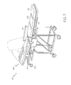
- FIG. 7 is a perspective view of a roll-in chair cot according to an embodiment of the present invention, showing the cot in a cot configuration located at a fully raised cot height position;
- FIGS. 8A , 8 B, and 8 C are perspective views of a roll-in chair cot according to an embodiment of the present invention, showing the cot in a chair configuration.
- FIG. 9 is a close-up diagrammatic view of one embodiment of a locking pin assembly of an embodiment of a roll-in chair cot according to the present invention.
- FIG. 10 is a diagrammatic view of another embodiment, with parts not illustrated, of a roll-in chair cot according to the present invention.
- the roll-in chair cot 10 includes a collapsible undercarriage, generally indicated by 20 , supportably connecting a roller base 30 to a support frame 40 .
- Roller base 30 includes a generally rectangular frame having members 32 , 32 A rotatably mounting castor wheels 34 at their respective ends. Each member pair 32 , 32 A slidably move or telescope relative to each other.
- the support frame 40 is rectangular in shape with three sides having frame members and a fourth side open to permit patient loading.
- the support frame 40 is generally comprising a pair of telescoping members 42 and cross members 44 .
- Each of the pair of telescoping members 42 include a swing-down side hand rail 46 which are pivotably connected thereto.
- Each side hand rail 46 is moveable between an upward position, such as is shown in FIG. 1A , a downward position, and a horizontal position.
- a locking mechanism 45 is adapted to releasably lock its respective side hand rail 46 in one of the above mentioned positions.
- Undercarriage 20 includes a first pair of fixed length legs 22 which are pivotally mounted to the support frame 40 and the roller base 30 such that the first pair of legs 22 may swing the roller base 30 generally parallel to the support frame 40 .
- the first pair of fixed length legs 22 pivotably connect a front end of roller base 30 to a front telescoping end 24 of telescoping member 42 , which is best shown in FIG. 2 .
- a second pair of fixed length legs 26 is pivotably connected at a rear end of roller base 30 at one end and pivotable and slidably connect at the other opposed end to telescoping member 42 .
- An optional combination bump guard and ground rolling wheel assembly 100 may be provided to each fixed length legs 26 as depicted in FIGS. 1B and 3A .
- a pair of diagonally extending braces 28 is pivotally mounted to the support frame 40 and the roller base 30 , in one embodiment as shown by FIGS. 1A and 1B , and in another embodiment as shown by FIG. 2 , to a lower end of the second pair of fixed length legs 26 above its pivot connect to the roller base 30 .
- the pair of diagonally extending braces 28 releasably support the legs 22 and 26 perpendicular to the roller base 30 and support frame 40 when the cot is positioned in the fully raised cot height position as illustrated in FIGS. 1A and 1B .
- each one of the pair of diagonally extending braces 28 have upper and lower links 23 a and 23 b , respectively, connected by a center hinge 21 . Since each lower link 23 b is pivotally mounted to either the roller base 30 or a respective one of the second pair of fixed length legs 26 , and each upper link 23 a is pivotally mounted to the support frame 40 , breaking the center hinge 21 will permit the support frame 40 to collapse along with roller base 30 into a fully retracted cot height position which is best illustrated by FIG. 3A . In the fully retracted cot height or lowered position, the roller base 30 , the wheel assembly 100 , and loading wheels 106 support the cot 10 on the ground.
- FIG. 3B is a side perspective view of the roll-in chair cot of FIG. 3A , with parts removed, to show the undercarriage thereof situated in a fully lowered cot height position.
- a conventional breaking mechanism (not shown) is used to facilitate the breaking or releasing of the braces 24 thereby permitting the roller base 30 to swing parallel to the support frame 40 into the fully retracted cot height position.
- One such conventional breaking mechanism is disclosed by commonly owned U.S. Pat. No. 3,289,219 to Ferneau et al., which is herein incorporated fully by reference.
- the cot 10 is further positionable in an intermediate cot height position which locates the support frame 40 at approximately bed height such that a patient may be laterally transferred from the bed to the cot 10 in a generally supine position.
- This intermediate cot height position is best illustrated by FIG. 4A , with some part removed for convenience of illustration, and FIG. 4B showing a preferred embodiment.
- a hand operated release mechanism 50 in one embodiment is operably connected to a pair of latches 52 each rotatably mounted to a respective one of the telescoping members 42 .
- Each latch 52 releasably holds a respective pin 52 provided on the second pair of fixed length legs 26 . Releasing the pins 54 from the latches 52 thereby permits the front telescoping end 24 of the telescoping members 42 to extend allowing the first pair of fixed length legs 22 to swing the support frame 40 parallel to the roller base 30 in the direction opposite from placing the cot 10 in the fully retracted cot height position.
- the hand operated release mechanism is connected to an internal locking mechanism situated inside each telescoping members 42 , having a latching pin arrangement 108 illustrated by FIG. 9 .
- the latching pin arrangement 108 includes a ball pin 110 biased to a seated position within a cavity 112 provided near the enclosed end of the front telescoping end 24 to the telescoping member 42 .
- a ramp portion 114 of a latch 116 will ride under the ball portion of the ball pin to unseat it from the cavity, thereby permitting the telescoping end 24 to freely slide within telescoping member 42 .
- the latch 116 is also biased to the locking position illustrated.
- a landing brace 104 automatically folds down from a stowed position illustrated by FIG. 3A to a deployed position as shown in FIG. 5A .
- the landing brace 104 provides additional stability to the cot when located in the intermediate position, such that the cot does not teeter.
- transitioning the cot 10 in the opposite direction from the intermediate cot height position will rotate the legs 22 , 26 and cross braces 28 until the latch 52 once again releasably holds the pins 54 , thereby securing the cot 10 once again in the fully extended cot height position illustrated by FIG. 1 .
- the latch 52 and pin 54 is best shown in FIG. 6 .
- Cot 10 further includes an articulated bed frame, generally indicated by 60 , which is adjustable between a cot configuration, such as shown in FIG. 7 with the cot in the fully elevated position, and a chair configuration, such as shown in FIGS. 8A , 8 B, and 8 C.
- Bed frame 60 comprises three main segments namely, a wheeled back segment 62 , a leg segment 64 and a seat segment 66 operably connected to each other between the pair of telescoping members 42 .
- Back segment 62 is pivotably connected to one of the cross members 44 .
- the seat segment 66 is generally horizontal and both the back segment 62 and the leg segment 64 are generally vertical relative to the base 30 as illustrated by FIG. 8A .
- the pair of loading wheels 106 are affixed to a free end of the support frame 40 , best shown by FIG. 8C , thereby defining a loading end of the cot 10 thereof.
- the front loading wheels 106 may be adjusted to allow for additional height as explained hereafter.
- the fixed length legs 26 may be releasably mounted to the wheeled base 30 via bracket 118 having a bolting pattern 120 .
- the bolting pattern 120 permits the height H of the loading wheels 106 to be adjustable. In one embodiment, the bolting pattern 120 permits adjusting the loading wheels 106 between a height H ranging from about 24′′ to about 34′′. It is to be appreciated that member pairs 32 , 32 A telescope when the cot is transitioned from a lower position to an elevated loading position as depicted in FIG. 10 , such that the center of gravity between the points of contact is kept on the ground such that the cot 10 does not tip.
- the back segment 62 further includes a frame like backrest member 70 that is pivotably mounted between the frame of the back segment 62 to one of the cross members 44 .
- a first extending member or biasing spring 72 ( FIG. 1A ) is connected at a first end to backrest member 70 adjacent a free end thereof, and at a second end to a cross member 74 .
- Biasing spring 72 provides a positive, tensile biasing force when activated.
- Lock release 84 is connected to backrest member 70 such that, depressing release 84 releases the locking mechanism within biasing spring 72 , thereby causing backrest member to pivot about the respective cross member 44 into an upright position from 0° to 90° or any position therebetween, such as illustrated by FIG. 7 , under the influence of the biasing force of the spring.
- the leg segment 64 connects at an upper end thereof to front ends of the pair of the telescoping members 42 .
- a foot support panel 76 is pivotably connected to the leg segment 64 .
- the foot support panel 76 may be elevated to provide a footrest to a reclined patient. In the cot position, the foot support panel 76 is normally stowed such as illustrated in FIG. 7 .
- the bed frame 60 may be situated in the chair configuration of FIG. 8A , a cot configuration of FIG. 1B , and a number of reclined positions therebetween. In one embodiment, transitioning the back segment 62 from the chair position to a reclined position, will also transition the leg segment 64 to the associated reclined position due to these segments being linked by push arm 83 .
- Seat segment 66 is positioned between the pair of telescoping members 42 and is pivotably connected at a rear end thereof.
- a front end of the seat segment 66 is connected to a rear end of the foot support panel 76 of the leg segment 62 by a leg support panel 65 , which is pivotably connected at a first end thereof to the seat segment 66 and which is pivotably connected at a second end thereof to the rear end of the foot support panel 76 .
- a pair of lift biasing springs 85 are each pivotably connected between the seat frame and the back frame.
- a single lift biasing spring or cylinder may be used.
- the pair of lift biasing springs 85 is constructed in a similar fashion as biasing spring 84 described above. It is to be appreciated that using the pair of lift biasing springs 85 reduces weight and allow infinite adjustment between the leg, seat, and back frames of the cot 10 to the chair configuration of FIG. 8A , a cot configuration of FIG. 1B , and a number of reclined positions therebetween, which allows a patient to find a chair angle that provides the most comfortable position.
- Pillows, pads or cushions or a full length mattress as shown in FIGS. 7 and 8 may be secured to support frame 40 to provide a comfortable resting place upon which the patient is situated. Additionally, the cot may be provided with a number of restraints as is customary in the art.
- the roll-in chair cot of the present invention is movable between three cot height positions: a fully lowered position, a fully elevated position, and an intermediate position locating the cot at approximately bed height such that a patient may be laterally transferred from the bed to the cot in a generally supine position.
- the roll-in chair cot readily converts from a level cot to a contoured chair for maneuvering ease in narrow hallways, elevators, and other confined spaces.
- the roll-in cot has folding legs for simple loading and unloading by two emergency medical technicians (EMTs) into the back of an emergency vehicle. Spring-actuated, folding legs minimize the lifting effort required by the EMTs.
- the supporting legs automatically lock into place when the undercarriage is fully unfolded.
- rectangular, tubular aluminum construction provides durability and strength.
- plastic bearings are provided on rotating components for easy movement.
- the wheels are greaseless wheels.
- the cot provides an adjustable backrest angle from 0° to 75° which allows a patient to be placed in a comfortable position during transport.
- Patient restraint system ensures safety of patient during transport, and in one embodiment comprises two across patient restraints and one shoulder harness.
- a full-length, sectional mattress provides comfort and folds with the cot as it is moved into the chair position. Swing-down side hand rails enable convenient patient transfer from hospital bed to cot.
Abstract
Description
Claims (18)
Priority Applications (1)
| Application Number | Priority Date | Filing Date | Title |
|---|---|---|---|
| US11/444,238 US7581265B1 (en) | 2005-06-03 | 2006-05-31 | Roll-in chair cot with three cot height positions |
Applications Claiming Priority (2)
| Application Number | Priority Date | Filing Date | Title |
|---|---|---|---|
| US68727905P | 2005-06-03 | 2005-06-03 | |
| US11/444,238 US7581265B1 (en) | 2005-06-03 | 2006-05-31 | Roll-in chair cot with three cot height positions |
Publications (1)
| Publication Number | Publication Date |
|---|---|
| US7581265B1 true US7581265B1 (en) | 2009-09-01 |
Family
ID=41009076
Family Applications (1)
| Application Number | Title | Priority Date | Filing Date |
|---|---|---|---|
| US11/444,238 Active 2027-02-05 US7581265B1 (en) | 2005-06-03 | 2006-05-31 | Roll-in chair cot with three cot height positions |
Country Status (1)
| Country | Link |
|---|---|
| US (1) | US7581265B1 (en) |
Cited By (13)
| Publication number | Priority date | Publication date | Assignee | Title |
|---|---|---|---|---|
| US20120073053A1 (en) * | 2010-09-24 | 2012-03-29 | Turner Jonathan D | Bed Frame, Mattress and Bed with Enhanced Chair Egress Capability |
| US20120235371A1 (en) * | 2011-03-15 | 2012-09-20 | Smith Craig S | Multiposition mechanic's creeper |
| CN103393506A (en) * | 2013-07-08 | 2013-11-20 | 中北大学 | Ambulance stretcher |
| US20150083771A1 (en) * | 2013-09-20 | 2015-03-26 | Lugino Barbisan | Paramedic chair carrier |
| US9095484B1 (en) | 2013-11-18 | 2015-08-04 | Lorraine E. Bethea | Wheelchair leg guard |
| RU2600709C2 (en) * | 2015-07-06 | 2016-10-27 | Общество с ограниченной ответственностью "Казанский агрегатный завод" | Medical stretcher (versions) |
| US9486373B2 (en) | 2013-03-14 | 2016-11-08 | Stryker Corporation | Reconfigurable patient support |
| US9510981B2 (en) | 2013-03-14 | 2016-12-06 | Stryker Corporation | Reconfigurable transport apparatus |
| US9603764B2 (en) | 2014-02-11 | 2017-03-28 | Medline Industries, Inc. | Method and apparatus for a locking caster |
| WO2020049548A3 (en) * | 2019-12-26 | 2020-09-10 | Universidad Técnica Particular De Loja | Smart bed that can be converted into a walker for assisting a user with physical problems |
| US11679045B2 (en) | 2019-12-30 | 2023-06-20 | Stryker Corporation | Patient transport apparatus user interface |
| US11696860B2 (en) | 2019-12-30 | 2023-07-11 | Stryker Corporation | Patient transport apparatus with multiple mode handle assembly |
| US11938068B2 (en) | 2019-12-30 | 2024-03-26 | Stryker Corporation | Patient transport apparatus drive systems |
Citations (11)
| Publication number | Priority date | Publication date | Assignee | Title |
|---|---|---|---|---|
| US3122758A (en) | 1962-11-13 | 1964-03-03 | Ferno Mfg Company | Combined stretcher and stair chair |
| US3137511A (en) | 1961-04-05 | 1964-06-16 | Weil | Stretcher chair |
| US3289219A (en) * | 1964-10-12 | 1966-12-06 | Weil Burt | Combined ambulance cart and rolling chair |
| US3380085A (en) | 1966-10-24 | 1968-04-30 | Ferno Washington | Multi-purpose stretcher chair |
| US4105242A (en) | 1977-03-02 | 1978-08-08 | Terbeek Howard G | Mobile chair |
| US4688279A (en) | 1986-07-24 | 1987-08-25 | Ferno-Washington, Inc. | Combination stretcher and stairchair |
| US4949410A (en) | 1988-03-11 | 1990-08-21 | Hausted, Inc. | Guard rail for patient transport apparatus hospital beds and the like |
| US5022105A (en) | 1989-08-04 | 1991-06-11 | Michael Catoe | Mobile lift-assisted patient transport device for field use |
| US6381781B1 (en) | 1999-08-24 | 2002-05-07 | Ferno-Washington, Inc. | Combination ambulance cot and chair |
| US7124454B2 (en) * | 2003-01-14 | 2006-10-24 | Walkingshaw Nathan R | Pneumatic cot for use with emergency vehicles |
| US7140055B2 (en) * | 2003-07-18 | 2006-11-28 | Joseph Bishop | Lightweight mobile lift-assisted patient transport device |
-
2006
- 2006-05-31 US US11/444,238 patent/US7581265B1/en active Active
Patent Citations (11)
| Publication number | Priority date | Publication date | Assignee | Title |
|---|---|---|---|---|
| US3137511A (en) | 1961-04-05 | 1964-06-16 | Weil | Stretcher chair |
| US3122758A (en) | 1962-11-13 | 1964-03-03 | Ferno Mfg Company | Combined stretcher and stair chair |
| US3289219A (en) * | 1964-10-12 | 1966-12-06 | Weil Burt | Combined ambulance cart and rolling chair |
| US3380085A (en) | 1966-10-24 | 1968-04-30 | Ferno Washington | Multi-purpose stretcher chair |
| US4105242A (en) | 1977-03-02 | 1978-08-08 | Terbeek Howard G | Mobile chair |
| US4688279A (en) | 1986-07-24 | 1987-08-25 | Ferno-Washington, Inc. | Combination stretcher and stairchair |
| US4949410A (en) | 1988-03-11 | 1990-08-21 | Hausted, Inc. | Guard rail for patient transport apparatus hospital beds and the like |
| US5022105A (en) | 1989-08-04 | 1991-06-11 | Michael Catoe | Mobile lift-assisted patient transport device for field use |
| US6381781B1 (en) | 1999-08-24 | 2002-05-07 | Ferno-Washington, Inc. | Combination ambulance cot and chair |
| US7124454B2 (en) * | 2003-01-14 | 2006-10-24 | Walkingshaw Nathan R | Pneumatic cot for use with emergency vehicles |
| US7140055B2 (en) * | 2003-07-18 | 2006-11-28 | Joseph Bishop | Lightweight mobile lift-assisted patient transport device |
Cited By (22)
| Publication number | Priority date | Publication date | Assignee | Title |
|---|---|---|---|---|
| US9149403B2 (en) * | 2010-09-24 | 2015-10-06 | Hill-Rom Services, Inc. | Bed frame, mattress and bed with enhanced chair egress capability |
| US10272007B2 (en) * | 2010-09-24 | 2019-04-30 | Hill-Rom Services, Inc. | Bed frame, mattress and bed with enhanced chair egress capability |
| US20120073053A1 (en) * | 2010-09-24 | 2012-03-29 | Turner Jonathan D | Bed Frame, Mattress and Bed with Enhanced Chair Egress Capability |
| US20120235371A1 (en) * | 2011-03-15 | 2012-09-20 | Smith Craig S | Multiposition mechanic's creeper |
| US9510981B2 (en) | 2013-03-14 | 2016-12-06 | Stryker Corporation | Reconfigurable transport apparatus |
| US11071661B2 (en) | 2013-03-14 | 2021-07-27 | Stryker Corporation | Transport apparatus |
| US11737933B2 (en) | 2013-03-14 | 2023-08-29 | Stryker Corporation | Transport apparatus |
| US10406043B2 (en) | 2013-03-14 | 2019-09-10 | Stryker Corporation | Transport apparatus |
| US9925098B2 (en) | 2013-03-14 | 2018-03-27 | Stryker Corporation | Reconfigurable transport apparatus |
| US9486373B2 (en) | 2013-03-14 | 2016-11-08 | Stryker Corporation | Reconfigurable patient support |
| CN103393506A (en) * | 2013-07-08 | 2013-11-20 | 中北大学 | Ambulance stretcher |
| CN103393506B (en) * | 2013-07-08 | 2015-10-14 | 中北大学 | Stretcher cart for giving first aid |
| US20150083771A1 (en) * | 2013-09-20 | 2015-03-26 | Lugino Barbisan | Paramedic chair carrier |
| US9308140B2 (en) * | 2013-09-20 | 2016-04-12 | Lugino Barbisan | Paramedic chair carrier |
| US9095484B1 (en) | 2013-11-18 | 2015-08-04 | Lorraine E. Bethea | Wheelchair leg guard |
| US9603764B2 (en) | 2014-02-11 | 2017-03-28 | Medline Industries, Inc. | Method and apparatus for a locking caster |
| US9993378B2 (en) | 2014-02-11 | 2018-06-12 | Medline Industries, Inc. | Method and apparatus for a locking caster |
| RU2600709C2 (en) * | 2015-07-06 | 2016-10-27 | Общество с ограниченной ответственностью "Казанский агрегатный завод" | Medical stretcher (versions) |
| WO2020049548A3 (en) * | 2019-12-26 | 2020-09-10 | Universidad Técnica Particular De Loja | Smart bed that can be converted into a walker for assisting a user with physical problems |
| US11679045B2 (en) | 2019-12-30 | 2023-06-20 | Stryker Corporation | Patient transport apparatus user interface |
| US11696860B2 (en) | 2019-12-30 | 2023-07-11 | Stryker Corporation | Patient transport apparatus with multiple mode handle assembly |
| US11938068B2 (en) | 2019-12-30 | 2024-03-26 | Stryker Corporation | Patient transport apparatus drive systems |
Similar Documents
| Publication | Publication Date | Title |
|---|---|---|
| US7581265B1 (en) | Roll-in chair cot with three cot height positions | |
| US6381781B1 (en) | Combination ambulance cot and chair | |
| US8104121B2 (en) | Combination ambulance cot and chair | |
| US6374436B1 (en) | Hospital bed | |
| US7302718B2 (en) | Multiple level roll-in cot | |
| US6389623B1 (en) | Ambulance stretcher with improved height adjustment feature | |
| US6112345A (en) | Hospital bed | |
| US11337875B2 (en) | Wheelchair lift-transfer device | |
| US3644944A (en) | Ambulance cot construction | |
| US5283919A (en) | Folding trauma stretcher | |
| US5435027A (en) | Roll-in cot with high ground clearance | |
| US7472921B2 (en) | Assistive mobility device | |
| US6799770B2 (en) | Reclinable wheelchair | |
| US7003829B2 (en) | Stretcher with gear mechanism for adjustable height | |
| US20150342805A1 (en) | Mobile transportation device convertible to a trendelenburg table and for use in a motor vehicle and method thereof | |
| US20060261569A1 (en) | Mobility assist devices | |
| US20150283017A1 (en) | Mobile transportation device convertible to an examination table and for use in a motor vehicle and method thereof | |
| CA2620411C (en) | Adjustable patient transport system | |
| WO2002039944A2 (en) | Multipurpose roll-in emergency cot | |
| US7487989B2 (en) | Wheelchair with retractable storing leg rests | |
| JPS6134339B2 (en) | ||
| CN215385253U (en) | Multifunctional stretcher vehicle | |
| CA2416123A1 (en) | Epidural patient support | |
| JP4403567B2 (en) | Wheelchair chassis | |
| ITTO960106U1 (en) | CHAIR FOR MEDICAL USE CONVERTIBLE INTO STRETCHER. |
Legal Events
| Date | Code | Title | Description |
|---|---|---|---|
| AS | Assignment |
Owner name: U. S. BANK NATIONAL ASSOCIATION, OHIO Free format text: MORTGAGE;ASSIGNOR:FERNO-WASHINGTON, INC.;REEL/FRAME:018616/0238 Effective date: 20061208 Owner name: U. S. BANK NATIONAL ASSOCIATION,OHIO Free format text: MORTGAGE;ASSIGNOR:FERNO-WASHINGTON, INC.;REEL/FRAME:018616/0238 Effective date: 20061208 |
|
| AS | Assignment |
Owner name: FERNO-WASHINGTON, INC., OHIO Free format text: ASSIGNMENT OF ASSIGNORS INTEREST;ASSIGNORS:BOURGRAF, ELROY E.;BOURGRAF, ELROY E., JR.;POLLOCK, IRVIN;REEL/FRAME:018671/0870 Effective date: 20060926 |
|
| STCF | Information on status: patent grant |
Free format text: PATENTED CASE |
|
| CC | Certificate of correction | ||
| REMI | Maintenance fee reminder mailed | ||
| FPAY | Fee payment |
Year of fee payment: 4 |
|
| SULP | Surcharge for late payment | ||
| FEPP | Fee payment procedure |
Free format text: PAYOR NUMBER ASSIGNED (ORIGINAL EVENT CODE: ASPN); ENTITY STATUS OF PATENT OWNER: LARGE ENTITY |
|
| FPAY | Fee payment |
Year of fee payment: 8 |
|
| MAFP | Maintenance fee payment |
Free format text: PAYMENT OF MAINTENANCE FEE, 12TH YEAR, LARGE ENTITY (ORIGINAL EVENT CODE: M1553); ENTITY STATUS OF PATENT OWNER: LARGE ENTITY Year of fee payment: 12 |