US7618425B2 - Endoscopic suturing system - Google Patents
Endoscopic suturing system Download PDFInfo
- Publication number
- US7618425B2 US7618425B2 US10/353,866 US35386603A US7618425B2 US 7618425 B2 US7618425 B2 US 7618425B2 US 35386603 A US35386603 A US 35386603A US 7618425 B2 US7618425 B2 US 7618425B2
- Authority
- US
- United States
- Prior art keywords
- needle
- distal end
- members
- end portion
- endoscope
- Prior art date
- Legal status (The legal status is an assumption and is not a legal conclusion. Google has not performed a legal analysis and makes no representation as to the accuracy of the status listed.)
- Active, expires
Links
- 230000005540 biological transmission Effects 0.000 claims abstract description 45
- 238000011282 treatment Methods 0.000 claims abstract description 22
- 238000012277 endoscopic treatment Methods 0.000 claims abstract description 15
- 230000007246 mechanism Effects 0.000 claims description 13
- 230000008602 contraction Effects 0.000 claims description 7
- 238000011084 recovery Methods 0.000 claims description 5
- 230000001681 protective effect Effects 0.000 claims 1
- 230000000694 effects Effects 0.000 description 21
- 238000000034 method Methods 0.000 description 21
- 238000005520 cutting process Methods 0.000 description 17
- 239000011347 resin Substances 0.000 description 16
- 229920005989 resin Polymers 0.000 description 16
- 230000008901 benefit Effects 0.000 description 10
- 229920002530 polyetherether ketone Polymers 0.000 description 10
- 239000000463 material Substances 0.000 description 9
- 239000012530 fluid Substances 0.000 description 7
- -1 silk Polymers 0.000 description 7
- 229920002313 fluoropolymer Polymers 0.000 description 6
- 229910052751 metal Inorganic materials 0.000 description 6
- 239000002184 metal Substances 0.000 description 6
- 229920000106 Liquid crystal polymer Polymers 0.000 description 5
- 239000004977 Liquid-crystal polymers (LCPs) Substances 0.000 description 5
- 239000004677 Nylon Substances 0.000 description 5
- 239000004952 Polyamide Substances 0.000 description 5
- 239000004642 Polyimide Substances 0.000 description 5
- 229910052581 Si3N4 Inorganic materials 0.000 description 5
- 229910001069 Ti alloy Inorganic materials 0.000 description 5
- RTAQQCXQSZGOHL-UHFFFAOYSA-N Titanium Chemical compound [Ti] RTAQQCXQSZGOHL-UHFFFAOYSA-N 0.000 description 5
- PNEYBMLMFCGWSK-UHFFFAOYSA-N aluminium oxide Inorganic materials [O-2].[O-2].[O-2].[Al+3].[Al+3] PNEYBMLMFCGWSK-UHFFFAOYSA-N 0.000 description 5
- 238000013459 approach Methods 0.000 description 5
- 229910010293 ceramic material Inorganic materials 0.000 description 5
- 230000004048 modification Effects 0.000 description 5
- 238000012986 modification Methods 0.000 description 5
- 229920001778 nylon Polymers 0.000 description 5
- 229920002492 poly(sulfone) Polymers 0.000 description 5
- 229920002647 polyamide Polymers 0.000 description 5
- 229920000728 polyester Polymers 0.000 description 5
- 229920001721 polyimide Polymers 0.000 description 5
- 238000007789 sealing Methods 0.000 description 5
- HQVNEWCFYHHQES-UHFFFAOYSA-N silicon nitride Chemical compound N12[Si]34N5[Si]62N3[Si]51N64 HQVNEWCFYHHQES-UHFFFAOYSA-N 0.000 description 5
- 238000005476 soldering Methods 0.000 description 5
- 239000010935 stainless steel Substances 0.000 description 5
- 229910001220 stainless steel Inorganic materials 0.000 description 5
- 239000010936 titanium Substances 0.000 description 5
- 229910052719 titanium Inorganic materials 0.000 description 5
- 238000001574 biopsy Methods 0.000 description 4
- 238000005219 brazing Methods 0.000 description 4
- 239000000470 constituent Substances 0.000 description 3
- 238000012545 processing Methods 0.000 description 3
- 239000007779 soft material Substances 0.000 description 3
- XUIMIQQOPSSXEZ-UHFFFAOYSA-N Silicon Chemical compound [Si] XUIMIQQOPSSXEZ-UHFFFAOYSA-N 0.000 description 2
- 208000027418 Wounds and injury Diseases 0.000 description 2
- 239000000853 adhesive Substances 0.000 description 2
- 230000001070 adhesive effect Effects 0.000 description 2
- 210000000078 claw Anatomy 0.000 description 2
- 230000006378 damage Effects 0.000 description 2
- 230000003247 decreasing effect Effects 0.000 description 2
- 208000014674 injury Diseases 0.000 description 2
- 238000003780 insertion Methods 0.000 description 2
- 230000037431 insertion Effects 0.000 description 2
- 230000002093 peripheral effect Effects 0.000 description 2
- 238000003825 pressing Methods 0.000 description 2
- 229910052710 silicon Inorganic materials 0.000 description 2
- 239000010703 silicon Substances 0.000 description 2
- 239000002390 adhesive tape Substances 0.000 description 1
- 239000003570 air Substances 0.000 description 1
- 238000005452 bending Methods 0.000 description 1
- 230000015572 biosynthetic process Effects 0.000 description 1
- 239000007767 bonding agent Substances 0.000 description 1
- 150000001925 cycloalkenes Chemical class 0.000 description 1
- 230000002452 interceptive effect Effects 0.000 description 1
- 239000007788 liquid Substances 0.000 description 1
- JFNLZVQOOSMTJK-KNVOCYPGSA-N norbornene Chemical compound C1[C@@H]2CC[C@H]1C=C2 JFNLZVQOOSMTJK-KNVOCYPGSA-N 0.000 description 1
- 239000002504 physiological saline solution Substances 0.000 description 1
- 229920000515 polycarbonate Polymers 0.000 description 1
- 239000004417 polycarbonate Substances 0.000 description 1
- 229920000139 polyethylene terephthalate Polymers 0.000 description 1
- 239000005020 polyethylene terephthalate Substances 0.000 description 1
- 229920001296 polysiloxane Polymers 0.000 description 1
- 239000004810 polytetrafluoroethylene Substances 0.000 description 1
- 229920001343 polytetrafluoroethylene Polymers 0.000 description 1
- 239000012858 resilient material Substances 0.000 description 1
- 238000003892 spreading Methods 0.000 description 1
- 230000007480 spreading Effects 0.000 description 1
- 230000031068 symbiosis, encompassing mutualism through parasitism Effects 0.000 description 1
- 238000005406 washing Methods 0.000 description 1
- XLYOFNOQVPJJNP-UHFFFAOYSA-N water Substances O XLYOFNOQVPJJNP-UHFFFAOYSA-N 0.000 description 1
- 238000003466 welding Methods 0.000 description 1
- 238000004804 winding Methods 0.000 description 1
Images


Classifications
-
- A—HUMAN NECESSITIES
- A61—MEDICAL OR VETERINARY SCIENCE; HYGIENE
- A61B—DIAGNOSIS; SURGERY; IDENTIFICATION
- A61B17/00—Surgical instruments, devices or methods, e.g. tourniquets
- A61B17/04—Surgical instruments, devices or methods, e.g. tourniquets for suturing wounds; Holders or packages for needles or suture materials
- A61B17/0467—Instruments for cutting sutures
-
- A—HUMAN NECESSITIES
- A61—MEDICAL OR VETERINARY SCIENCE; HYGIENE
- A61B—DIAGNOSIS; SURGERY; IDENTIFICATION
- A61B17/00—Surgical instruments, devices or methods, e.g. tourniquets
- A61B17/04—Surgical instruments, devices or methods, e.g. tourniquets for suturing wounds; Holders or packages for needles or suture materials
- A61B17/0469—Suturing instruments for use in minimally invasive surgery, e.g. endoscopic surgery
-
- A—HUMAN NECESSITIES
- A61—MEDICAL OR VETERINARY SCIENCE; HYGIENE
- A61B—DIAGNOSIS; SURGERY; IDENTIFICATION
- A61B17/00—Surgical instruments, devices or methods, e.g. tourniquets
- A61B17/04—Surgical instruments, devices or methods, e.g. tourniquets for suturing wounds; Holders or packages for needles or suture materials
- A61B17/0487—Suture clamps, clips or locks, e.g. for replacing suture knots; Instruments for applying or removing suture clamps, clips or locks
-
- A—HUMAN NECESSITIES
- A61—MEDICAL OR VETERINARY SCIENCE; HYGIENE
- A61B—DIAGNOSIS; SURGERY; IDENTIFICATION
- A61B17/00—Surgical instruments, devices or methods, e.g. tourniquets
- A61B17/04—Surgical instruments, devices or methods, e.g. tourniquets for suturing wounds; Holders or packages for needles or suture materials
- A61B17/0485—Devices or means, e.g. loops, for capturing the suture thread and threading it through an opening of a suturing instrument or needle eyelet
-
- A—HUMAN NECESSITIES
- A61—MEDICAL OR VETERINARY SCIENCE; HYGIENE
- A61B—DIAGNOSIS; SURGERY; IDENTIFICATION
- A61B17/00—Surgical instruments, devices or methods, e.g. tourniquets
- A61B17/04—Surgical instruments, devices or methods, e.g. tourniquets for suturing wounds; Holders or packages for needles or suture materials
- A61B17/0493—Protective devices for suturing, i.e. for protecting the patient's organs or the operator
-
- A—HUMAN NECESSITIES
- A61—MEDICAL OR VETERINARY SCIENCE; HYGIENE
- A61B—DIAGNOSIS; SURGERY; IDENTIFICATION
- A61B17/00—Surgical instruments, devices or methods, e.g. tourniquets
- A61B17/04—Surgical instruments, devices or methods, e.g. tourniquets for suturing wounds; Holders or packages for needles or suture materials
- A61B17/06—Needles ; Sutures; Needle-suture combinations; Holders or packages for needles or suture materials
- A61B17/06066—Needles, e.g. needle tip configurations
-
- A—HUMAN NECESSITIES
- A61—MEDICAL OR VETERINARY SCIENCE; HYGIENE
- A61B—DIAGNOSIS; SURGERY; IDENTIFICATION
- A61B17/00—Surgical instruments, devices or methods, e.g. tourniquets
- A61B17/064—Surgical staples, i.e. penetrating the tissue
- A61B17/0643—Surgical staples, i.e. penetrating the tissue with separate closing member, e.g. for interlocking with staple
-
- A—HUMAN NECESSITIES
- A61—MEDICAL OR VETERINARY SCIENCE; HYGIENE
- A61B—DIAGNOSIS; SURGERY; IDENTIFICATION
- A61B17/00—Surgical instruments, devices or methods, e.g. tourniquets
- A61B17/04—Surgical instruments, devices or methods, e.g. tourniquets for suturing wounds; Holders or packages for needles or suture materials
- A61B17/0401—Suture anchors, buttons or pledgets, i.e. means for attaching sutures to bone, cartilage or soft tissue; Instruments for applying or removing suture anchors
- A61B2017/0445—Suture anchors, buttons or pledgets, i.e. means for attaching sutures to bone, cartilage or soft tissue; Instruments for applying or removing suture anchors cannulated, e.g. with a longitudinal through-hole for passage of an instrument
-
- A—HUMAN NECESSITIES
- A61—MEDICAL OR VETERINARY SCIENCE; HYGIENE
- A61B—DIAGNOSIS; SURGERY; IDENTIFICATION
- A61B17/00—Surgical instruments, devices or methods, e.g. tourniquets
- A61B17/04—Surgical instruments, devices or methods, e.g. tourniquets for suturing wounds; Holders or packages for needles or suture materials
- A61B17/0401—Suture anchors, buttons or pledgets, i.e. means for attaching sutures to bone, cartilage or soft tissue; Instruments for applying or removing suture anchors
- A61B2017/0446—Means for attaching and blocking the suture in the suture anchor
- A61B2017/0448—Additional elements on or within the anchor
- A61B2017/045—Additional elements on or within the anchor snug fit within the anchor
-
- A—HUMAN NECESSITIES
- A61—MEDICAL OR VETERINARY SCIENCE; HYGIENE
- A61B—DIAGNOSIS; SURGERY; IDENTIFICATION
- A61B17/00—Surgical instruments, devices or methods, e.g. tourniquets
- A61B17/04—Surgical instruments, devices or methods, e.g. tourniquets for suturing wounds; Holders or packages for needles or suture materials
- A61B17/0401—Suture anchors, buttons or pledgets, i.e. means for attaching sutures to bone, cartilage or soft tissue; Instruments for applying or removing suture anchors
- A61B2017/0446—Means for attaching and blocking the suture in the suture anchor
- A61B2017/0458—Longitudinal through hole, e.g. suture blocked by a distal suture knot
-
- A—HUMAN NECESSITIES
- A61—MEDICAL OR VETERINARY SCIENCE; HYGIENE
- A61B—DIAGNOSIS; SURGERY; IDENTIFICATION
- A61B17/00—Surgical instruments, devices or methods, e.g. tourniquets
- A61B17/04—Surgical instruments, devices or methods, e.g. tourniquets for suturing wounds; Holders or packages for needles or suture materials
- A61B17/0401—Suture anchors, buttons or pledgets, i.e. means for attaching sutures to bone, cartilage or soft tissue; Instruments for applying or removing suture anchors
- A61B2017/0464—Suture anchors, buttons or pledgets, i.e. means for attaching sutures to bone, cartilage or soft tissue; Instruments for applying or removing suture anchors for soft tissue
-
- A—HUMAN NECESSITIES
- A61—MEDICAL OR VETERINARY SCIENCE; HYGIENE
- A61B—DIAGNOSIS; SURGERY; IDENTIFICATION
- A61B17/00—Surgical instruments, devices or methods, e.g. tourniquets
- A61B17/04—Surgical instruments, devices or methods, e.g. tourniquets for suturing wounds; Holders or packages for needles or suture materials
- A61B17/0469—Suturing instruments for use in minimally invasive surgery, e.g. endoscopic surgery
- A61B2017/0472—Multiple-needled, e.g. double-needled, instruments
-
- A—HUMAN NECESSITIES
- A61—MEDICAL OR VETERINARY SCIENCE; HYGIENE
- A61B—DIAGNOSIS; SURGERY; IDENTIFICATION
- A61B17/00—Surgical instruments, devices or methods, e.g. tourniquets
- A61B17/04—Surgical instruments, devices or methods, e.g. tourniquets for suturing wounds; Holders or packages for needles or suture materials
- A61B17/0469—Suturing instruments for use in minimally invasive surgery, e.g. endoscopic surgery
- A61B2017/0474—Knot pushers
-
- A—HUMAN NECESSITIES
- A61—MEDICAL OR VETERINARY SCIENCE; HYGIENE
- A61B—DIAGNOSIS; SURGERY; IDENTIFICATION
- A61B17/00—Surgical instruments, devices or methods, e.g. tourniquets
- A61B17/04—Surgical instruments, devices or methods, e.g. tourniquets for suturing wounds; Holders or packages for needles or suture materials
- A61B17/0469—Suturing instruments for use in minimally invasive surgery, e.g. endoscopic surgery
- A61B2017/0475—Suturing instruments for use in minimally invasive surgery, e.g. endoscopic surgery using sutures having a slip knot
-
- A—HUMAN NECESSITIES
- A61—MEDICAL OR VETERINARY SCIENCE; HYGIENE
- A61B—DIAGNOSIS; SURGERY; IDENTIFICATION
- A61B17/00—Surgical instruments, devices or methods, e.g. tourniquets
- A61B17/04—Surgical instruments, devices or methods, e.g. tourniquets for suturing wounds; Holders or packages for needles or suture materials
- A61B17/0469—Suturing instruments for use in minimally invasive surgery, e.g. endoscopic surgery
- A61B2017/0477—Suturing instruments for use in minimally invasive surgery, e.g. endoscopic surgery with pre-tied sutures
-
- A—HUMAN NECESSITIES
- A61—MEDICAL OR VETERINARY SCIENCE; HYGIENE
- A61B—DIAGNOSIS; SURGERY; IDENTIFICATION
- A61B17/00—Surgical instruments, devices or methods, e.g. tourniquets
- A61B17/04—Surgical instruments, devices or methods, e.g. tourniquets for suturing wounds; Holders or packages for needles or suture materials
- A61B17/0487—Suture clamps, clips or locks, e.g. for replacing suture knots; Instruments for applying or removing suture clamps, clips or locks
- A61B2017/0488—Instruments for applying suture clamps, clips or locks
-
- A—HUMAN NECESSITIES
- A61—MEDICAL OR VETERINARY SCIENCE; HYGIENE
- A61B—DIAGNOSIS; SURGERY; IDENTIFICATION
- A61B17/00—Surgical instruments, devices or methods, e.g. tourniquets
- A61B17/04—Surgical instruments, devices or methods, e.g. tourniquets for suturing wounds; Holders or packages for needles or suture materials
- A61B17/06—Needles ; Sutures; Needle-suture combinations; Holders or packages for needles or suture materials
- A61B17/06004—Means for attaching suture to needle
- A61B2017/06019—Means for attaching suture to needle by means of a suture-receiving lateral eyelet machined in the needle
-
- A—HUMAN NECESSITIES
- A61—MEDICAL OR VETERINARY SCIENCE; HYGIENE
- A61B—DIAGNOSIS; SURGERY; IDENTIFICATION
- A61B17/00—Surgical instruments, devices or methods, e.g. tourniquets
- A61B17/04—Surgical instruments, devices or methods, e.g. tourniquets for suturing wounds; Holders or packages for needles or suture materials
- A61B17/06—Needles ; Sutures; Needle-suture combinations; Holders or packages for needles or suture materials
- A61B17/06004—Means for attaching suture to needle
- A61B2017/06028—Means for attaching suture to needle by means of a cylindrical longitudinal blind bore machined at the suture-receiving end of the needle, e.g. opposite to needle tip
-
- A—HUMAN NECESSITIES
- A61—MEDICAL OR VETERINARY SCIENCE; HYGIENE
- A61B—DIAGNOSIS; SURGERY; IDENTIFICATION
- A61B17/00—Surgical instruments, devices or methods, e.g. tourniquets
- A61B17/04—Surgical instruments, devices or methods, e.g. tourniquets for suturing wounds; Holders or packages for needles or suture materials
- A61B17/06—Needles ; Sutures; Needle-suture combinations; Holders or packages for needles or suture materials
- A61B17/06004—Means for attaching suture to needle
- A61B2017/06042—Means for attaching suture to needle located close to needle tip
-
- A—HUMAN NECESSITIES
- A61—MEDICAL OR VETERINARY SCIENCE; HYGIENE
- A61B—DIAGNOSIS; SURGERY; IDENTIFICATION
- A61B17/00—Surgical instruments, devices or methods, e.g. tourniquets
- A61B17/04—Surgical instruments, devices or methods, e.g. tourniquets for suturing wounds; Holders or packages for needles or suture materials
- A61B17/06—Needles ; Sutures; Needle-suture combinations; Holders or packages for needles or suture materials
- A61B2017/06057—Double-armed sutures, i.e. sutures having a needle attached to each end
Definitions
- the present invention relates to a treatment device which can be inserted into a body together with an endoscope.
- U.S. Pat. No. 5,171,258 (Symbiosis Co., Ltd.) discloses a medical instrument that is applicable to a surgical operation using a laparoscope.
- This medical instrument comprises a pair of posts for supporting a pair of devises in order to produce a large force required to grip a thick tissue.
- the posts and devises interfere with each other, whereby an angle that can be formed between the devises is restricted to an angle of about 90 degrees.
- a treatment device is required to be a small size, nevertheless the treatment device being capable of moving a needle over a large angle, is required. Further, it is required to transmit a large force to the needle in order to securely puncture the tissue.
- the present invention has been made in view of the above described circumstance. It is an object of the present invention to provide an endoscopic treatment device comprising a structure for further increasing an opening/closing angle and further producing a large force.
- a treatment device which is used to perform treatment in a body by being operated outside the body.
- This treatment device comprises a flexible member having a distal end portion that can be inserted into a body, a link mechanism which is arranged at the distal end portion of the flexible member and actuated by an operation outside the body, and a curved needle which is actuated by the link mechanism and can move in a direction to puncture a tissue and a direction to be removed from the tissue.
- an endoscopic treatment device which is used together with an endoscope to perform treatment in a body by being operated outside the body.
- This endoscopic treatment device comprises a transmission member with a flexible structure which has a distal end portion inserted into a body and can be operated outside the body, a push rod coupled to the distal end portion of the transmission member, first and second connecting members coupled to the push rod, each of the first and second connecting members having a distal end portion and a proximal end portion rotatably coupled to the push rod, first and second arm members each having a distal end portion and a proximal end portion rotatably coupled to the distal end portion of a corresponding one of the first and second connecting members, a holding member which rotatably holds the distal end portions of the respective arm members at a predetermined interval therebetween, first and second actuating members which are integrally formed with the distal end portions of the arm members and can open/close when the transmission member actuates the first and second connecting members and
- an endoscopic treatment device which includes recovery means for recovering the thread inserted into a tissue from a needle, wherein the recovery means has a lock member which detaches the needle from one of the first and second actuating members.
- an endoscopic treatment device comprising recovery means which is used together with an endoscope to recover a thread inserted into a tissue to perform treatment in a body by being operated outside the body, wherein the recovery means has a needle lock member which can lock a needle, and a thread lock member which can lock a thread, thereby forming needle/thread fixing means which can clamp a tissue between the needle locked to the needle lock member and the thread lock member.
- an endoscopic treatment device comprising a restriction mechanism which is mounted on at least one of first and second actuating members which can open/close, and restricts a movement range of one actuating member.
- an endoscopic treatment device which is used together with an endoscope to perform treatment in a body by being operated outside the body.
- This endoscopic treatment device comprises a transmission member with a flexible structure which has a distal end portion inserted into a body and can be operated outside the body, a push rod coupled to the distal end portion of the transmission member, first and second connecting members coupled to the push rod, each of the first and second connecting members having a distal end portion and a proximal end portion rotatably coupled to the push rod, first and second arm members each having a distal end portion and a proximal end portion rotatably coupled to the distal end portion of a corresponding one of the first and second connecting members, a holding member which rotatably holds the distal end portions of the respective arm members at a predetermined interval therebetween, first and second actuating members which are integrally formed with the distal end portions of the arm members and can open/close when the transmission member actuates the first and second connecting members
- FIG. 1 is an illustrative view showing an entire configuration of an endoscopic suturing system according to a first embodiment of the present invention
- FIG. 2 is an enlarged view of an endoscope and a suturing device shown in FIG. 1 ;
- FIG. 3 is an illustrative view showing a state in which first and second actuating members of the suturing device are closed;
- FIG. 4 is an illustrative view showing a state in which the first and second actuating members of the suturing device are opened;
- FIG. 5 is a sectional view showing an internal structure of the suturing device of FIG. 3 ;
- FIG. 6 is a sectional view showing an internal structure of the suturing device of FIG. 4 ;
- FIG. 7 is a sectional view taken along the line A-A of FIG. 5 ;
- FIG. 8 is a view seen in a direction indicated by the arrow B of FIG. 4 ;
- FIG. 8A is a view showing a suturing device when an endoscope is removed, the view being similar to FIG. 8 ;
- FIG. 9 is a sectional view taken along the line C-C of FIG. 7 ;
- FIG. 10 is a sectional view taken along the line D-D of FIG. 7 ;
- FIG. 11 is a sectional view taken along the line E-E of FIG. 7 ;
- FIG. 12 is a sectional view taken along the line F-F of FIG. 13 ;
- FIG. 13 is a view seen in a direction indicated by the arrow G of FIG. 7 ;
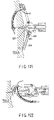
- FIG. 14 is a view showing a hook of a thread-catching-device when a suture thread is hooked
- FIG. 15 is a view showing a hook of a thread-catching-device when the suture thread and hook are retracted into a sheath;
- FIG. 15A is a view showing an outer appearance of another thread-catching-device
- FIG. 15B and FIG. 15C are views showing how the thread-catching-device catches a thread by using a hook
- FIG. 16 is a schematic longitudinal cross section of an insert assisting device
- FIG. 17 is an illustrative view showing a state in which an endoscope having a suturing device mounted thereon is housed in an insert assisting device;
- FIG. 18 is an illustrative view showing a state in which the endoscope having the suturing device mounted thereon is protruded from the insert assisting device;
- FIG. 19 is a view showing a modified example of a valve mounted on the insert assisting device.
- FIG. 20 is a view showing the insert assisting device according to a modified example when the endoscope and the suturing device are mounted;
- FIG. 21 is a view showing a state in which the endoscope and the suturing device are protruded from the insert assisting device of FIG. 20 ;
- FIG. 22 to FIG. 27 each show a suturing procedure using the suturing device, wherein FIG. 22 is a view showing a state in which a curved needle is proximal to a tissue;
- FIG. 23 is a view showing a state in which the curved needle punctures a tissue
- FIG. 24 is a view showing a state in which the thread-catching-device hooks the suture thread
- FIG. 25 is a view showing a state in which the suture thread is retracted into a flexible tubular member together with the hook when the thread is hooked;
- FIG. 26 is a view showing a state in which the thread-catching-device is pulled out from an instrument channel port
- FIG. 27 is a view showing a state in which the curved needle is removed from the tissue
- FIG. 28 is a view showing a state in which the suturing device is removed from the cavity together with the insert assisting device
- FIG. 29 is a view showing a state in which a knot is fed into a body by using a knot pusher
- FIG. 30 is a view showing a state in which the suturing device is housed in a protect member, the figure being similar to FIG. 2 showing an endoscopic suturing system according to a second embodiment of the present invention
- FIG. 31 is an illustrative view showing a state in which the suturing device is protruded in the endoscopic suturing system of FIG. 30 ;
- FIG. 32 to FIG. 35 are views each showing a protect member in the second embodiment, wherein FIG. 32 is a view showing a state in which a movable portion is protruded;
- FIG. 33 is a view showing a state in which a moving member disengages a lock member
- FIG. 34 is a view showing a state in which the movable portion is retracted
- FIG. 35 is a detailed view of the lock member
- FIG. 36 is an illustrative view of the protect member using an endoscopic suturing system according to a third embodiment of the present invention.
- FIG. 37 to FIG. 41 each show an endoscopic suturing system according to a fourth embodiment, wherein FIG. 37 is a view showing a suturing device used therefor;
- FIG. 38 is a view showing a state in which a removable needle after punctured into a tissue is engaged with a needle thread fixing device
- FIG. 39 is a view showing a state in which an injury is closed by tying the suture thread
- FIG. 40 is a view showing a state in which a redundant portion of the suture thread is cut by a thread cutting device
- FIG. 41 is a sectional view taken along the line H-H of FIG. 37 ;
- FIG. 42 is a sectional view showing a state in which sealing means is incorporated into the frontal side of the insert assisting device shown in FIG. 16 ;
- FIG. 43 is a sectional view taken along the line I-I of FIG. 42 ;
- FIG. 44 is a view showing a suturing device for use in an endoscopic suturing system according to a fifth embodiment of the present invention.
- FIG. 45 is a view showing a state in which a removable needle after punctured into a tissue is engaged with a needle thread fixing device
- FIG. 46 is a view showing a suturing device for use in an endoscopic suturing system according to a sixth embodiment of the present invention.
- FIG. 47 is a view showing a state in which a removable needle after punctured into a tissue is engaged with a needle fixing device
- FIG. 48 is a view showing a state in which a knot is formed by a loop removed from an engagingly lock member when the first and second actuating members are opened;
- FIG. 49 is a view showing a state in which a redundant portion of the suture thread is cut by a thread cutting device
- FIG. 50 is a view showing a state in which a tissue is sutured while the tissue is pulled by a grasping forceps;
- FIG. 51 is a view showing a state for use in an endoscopic suturing system according to a seventh embodiment of the present invention.
- FIG. 52 is a view showing a state when a removable needle after punctured into a tissue is engaged with a needle thread fixing device
- FIG. 53 is a sectional view taken along the line J-J of FIG. 52 ;
- FIG. 54 is a view showing a structure by thread lock means
- FIG. 54A to FIG. 54D are views showing various modifications of the lock means
- FIG. 55 is a view showing a state in which a needle holder is removed from a tissue
- FIG. 56 is a view showing a state in which a tissue is tied
- FIG. 57 to FIG. 63 each show a suturing procedure using an endoscopic suturing system according to an eighth embodiment of the present invention, wherein FIG. 57 is a view showing a state in which the suturing device is proximal to a tissue to be sutured;
- FIG. 58 is a view showing a state in which a removable needle after punctured into a tissue is engaged with a needle fixing device
- FIG. 59 is a view showing a state in which a needle holder is pulled out from a tissue
- FIG. 60 is a view showing a state in which the suturing device and endoscope are spaced from a tissue while the needle thread fixing device is left;
- FIG. 61 is a view showing a state in which a tissue is tied with the suture thread
- FIG. 62 is a view showing a state in which the suture thread can be separated
- FIG. 63 is a view showing a state in which a redundant portion of the suture thread is cut by a thread cutting device
- FIG. 64 is a view showing a suturing device for use in an endoscopic suturing system according to a ninth embodiment of the present invention.
- FIG. 65 is a view showing a state in which a removable needle after punctured into a tissue is engaged with a needle fixing device
- FIG. 66 is a view showing a tissue when the tissue is sutured
- FIG. 67 to FIG. 99 each show the 10th embodiment, wherein FIG. 67 is a sectional view taken along the line A-A of FIG. 68 ;
- FIG. 68 is a view showing an outer appearance of a suturing device (a view taken in the direction of an arrow B in FIG. 67 );
- FIG. 69 is a view taken in the direction of an arrow C in FIG. 67 (with a partially sectional view);
- FIG. 70 is a view taken in the direction of an arrow D in FIG. 69 ;
- FIG. 71 is a sectional view taken along the line E-E of FIG. 69 ;
- FIG. 72 is a sectional view taken along the line F-F of FIG. 69 ;
- FIG. 73 is a sectional view taken along the line G-G of FIG. 69 ;
- FIG. 74 is a view showing the details of the operating section of the suturing device.
- FIG. 75 is a sectional view taken along the line H-H of FIG. 74 ;
- FIG. 76 is a view showing an outer appearance of a pre-knot cartridge
- FIG. 77 to FIG. 80 are views for explaining how a removable needle is removed by using a needle-catching-device
- FIG. 81 to FIG. 85 are views showing how the removable needle is removed by using the needle-catching-device
- FIG. 86 and FIG. 87 are views showing a state wherein a cover is so mounted as to prevent a pre-knot of the pre-knot cartridge from coming off the needle-catching-device;
- FIG. 88 is a view showing an outer appearance of a spring for locking the removable needle mounted in the needle-catching-device
- FIG. 89 is a view showing in detail how a pre-knot is formed
- FIG. 90 to FIG. 98 are views showing a suturing procedure
- FIG. 99 is a view showing a needle-catching-sheath as another modification of the needle-catching-sheath
- FIG. 100 to FIG. 111 each show the 11th embodiment, wherein FIG. 100 is view showing an outer appearance of a suturing device (a view taken in the direction of an arrow G in FIG. 102 );
- FIG. 101 is a partially sectional view of FIG. 100 ;
- FIG. 102 is a sectional view taken along the line A-A of FIG. 100 ;
- FIG. 103 is a view taken in the direction of an arrow B in FIG. 101 ;
- FIG. 104 is a sectional view taken along the line C-C of FIG. 101 ;
- FIG. 105 is a sectional view taken along the line D-D of FIG. 101 ;
- FIG. 106 is a sectional view taken along the line E-E of FIG. 102 ;
- FIG. 107 is a sectional view taken along the line F-F of FIG. 102 ;
- FIG. 108 to FIG. 111 are views showing how the suturing device punctures the tissue
- FIG. 112 to FIG. 122 each show the 12th embodiment, wherein FIG. 112 is a view showing an outer appearance of a suturing device (a view taken in the direction of an arrow G in FIG. 114 );
- FIG. 113 is a partially sectional view of FIG. 112 ;
- FIG. 114 is a sectional view taken along the line A-A of FIG. 112 ;
- FIG. 115 is a view taken in the direction of an arrow B in FIG. 113 ;
- FIG. 116 is a sectional view taken along the line C-C of FIG. 113 ;
- FIG. 117 is a sectional view taken along the line E-E of FIG. 114 ;
- FIG. 118 is a sectional view taken along the line F-F of FIG. 114 ;
- FIG. 119 to FIG. 122 are views showing how the suturing device punctures the tissue
- FIG. 123 to FIG. 126B each show the 13th embodiment, wherein FIG. 123 to FIG. 126A are views showing how the suturing device punctures the tissue;
- FIG. 126B is a sectional view of the suturing device
- FIG. 127 to FIG. 128B each show the 14th embodiment, wherein FIG. 127 is a view showing a method of fixing a scope and a suturing device;
- FIG. 128A is a sectional view of a tube holder
- FIG. 128B is a view showing an arrangement obtained by mounting a protecting member in the arrangement shown in FIG. 127 ;
- FIG. 129 to FIG. 143 each show the 15th embodiment, wherein FIG. 129 to FIG. 141 are views showing a procedure for continuously suturing the tissue;
- FIG. 142 and FIG. 143 are views showing how a continuous suturing operation is performed
- FIG. 144 to FIG. 163 each show the 16th embodiment, wherein FIG. 144 is a partially sectional view of a suturing device
- FIG. 145 is a sectional view taken along the line A-A of FIG. 144 ;
- FIG. 146 is a partial sectional view of an end loop cartridge in FIG. 158 ;
- FIG. 147 to FIG. 157 are views showing the operation of a suturing device when puncturing the tissue
- FIG. 158 is a view showing an outer appearance of the end loop cartridge
- FIG. 159 is a view showing an outer appearance of a lock tubular member
- FIG. 160 and FIG. 161 are views showing a seal structure and operating section formed on the proximal end side of the suturing device
- FIG. 162 is a sectional view of the distal end portion of a thread cutting forceps used to cut a suture thread
- FIG. 163 is a view showing another example of the structure of an outer sheath
- FIG. 164 is a view showing a state wherein the end loop cartridge is loaded in a suturing device
- FIG. 165 and FIG. 166 are views showing another form of a removable needle
- FIG. 167 is a view showing a state wherein the suturing device is mounted on an endoscope and the distal end of the suturing device is brought nearest to the distal end of the endoscope;
- FIG. 168 is a view showing a state wherein the distal end of the suturing device is separated from the distal end of the endoscope;
- FIG. 169 to FIG. 171 each show the 17th embodiment, wherein FIG. 169 is a partial sectional view showing a state wherein the first and second actuating members of a suturing device are open;
- FIG. 170 is a partially sectional view showing a state wherein the first and second actuating members of the suturing device are closed;
- FIG. 171 is a sectional view taken along the line A-A of FIG. 169 ;
- FIG. 172 is a view showing a state wherein the tissue is punctured with a suturing device according to the 18th embodiment
- FIG. 173 and FIG. 174 are views showing a modification of a needle holder which can applied to the 10th embodiment
- FIG. 175 and FIG. 176 are views showing another modification of the needle holder
- FIG. 177 is a view showing a fixing needle which can applied to the 10th embodiment and other embodiments;
- FIG. 178 and FIG. 179 each show the 19th embodiment, wherein FIG. 178 is a view showing a state wherein an end loop cartridge is to be mounted in an engage tube, and FIG. 179 is a view showing a state wherein the end loop cartridge is mounted in the engage tube; and
- FIG. 180 and FIG. 181 each show the 20th embodiment, wherein FIG. 180 is a view showing a state wherein an end loop cartridge is to be mounted in an engage tube, and FIG. 181 is a view showing a state wherein the engage tube and a hood device are housed in a distal pipe.
- FIG. 1 to FIG. 29 show an endoscopic suturing system according to a first embodiment of the present invention.
- a gripping forceps a scissors forceps, a hot biopsy forceps, or a rotational clipping device may be used instead of the suturing system.
- an endoscopic suturing system 1 comprises an endoscope system 2 , a suturing device 3 , and a suture thread 4 .
- This suture thread 4 is preferably formed like a monofilament line or stranded wire by using a material such as nylon, polyester, silk, fluoroplastic or bioabsorbable resin.
- the endoscope system 2 comprises an endoscope 12 , an image processing device 14 , a light source device 15 , an observation monitor 13 , and a suction device 11 as in a generally used videoscope system.
- the endoscope 12 is connected to the light source device 15 via a universal code. Then, an image signal delivered from a CCD camera 10 (refer to FIG.
- the endoscope 12 is used as having an instrument channel port 6 , an endoscope of such type having two instrument channel ports may be used instead thereof.
- the CCD camera 10 , light guides 8 and 9 , instrument channel port 6 , and lens washing nozzle 11 for the CCD camera are arranged at a distal end portion of the endoscope 12 .
- a fiberscope with its eyepiece lens may be used instead of the videoscope using the CCD.
- the suturing device 3 is removably fixed at a distal end of the endoscope 12 by a fixing member 40 , the suturing device 3 and the endoscope 12 may be structured integrally with each other instead thereof.
- the suturing device 3 comprises a flexible tube 73 described later and a holding member 18 fixed at its distal end portion to hold a needle described later.
- This holding member 18 is formed of: two support plate portions 18 a opposed to each other through a slit 31 (refer to FIG. 7 ); and a hole 19 (refer to FIG. 5 ) which communicates with the slit 33 between these support plate portions and an inner hole of the flexible tube 73 .
- a push rod 20 is disposed retractably in an axial direction.
- first and second connecting members 22 and 23 are pivoted via a pin 21 .
- the other end of each of the connecting members 22 and 23 is pivoted at a proximal end portion of each of first and second arm members 24 and 25 via pins 26 and 27 , respectively.
- a first actuating member 16 formed integrally with the first arm member 24 is rotatably linked with the support plate portion 18 a via a pin 28 .
- a second actuating member 17 formed integrally with the second arm member 25 is rotatably linked with the support plate portion 18 a via a pin 29 .
- the pins 28 and 29 each have an end portion formed by a reduced diameter portion 30 .
- the size of the slit 31 defined between the support plate portions 18 a of the holding member 18 is maintained to be slightly larger than a sum of the thickness of the first actuating member 16 and the second actuating member 17 .
- the first actuating member 16 and the second actuating member 17 can be moved in the slit 31 without generating a remarkable friction.
- the push rod 20 is linked with an elongated flexible transmission member 71 .
- the holding member 18 is linked with coils 72 and 76 that form an axial hole.
- These coils 72 and 76 are linked with each other at their end faces opposed to each other by suitable means such as laser welding, blazing, soldering, adhering or the like.
- the coil 76 is formed of an element wire that is more smaller in diameter than the coil 72 , whereby the suturing device 3 is formed more flexibly at its distal end side.
- These coils 72 and 76 are covered with the flexible tube 73 almost all over their full lengths, and is held so as to be in intimate contact with this flexible tube 73 .
- the tube 73 restricts contraction in the axial direction of the coils 72 and 76 , thereby increasing a force for opening and closing the first actuating member 16 and the second actuating member 17 .
- frontal side end portions of the tube 73 and the coil 72 are fixed to an operating member main body 77 of an operating member 67 of the suturing device.
- a frontal side end portion of the transmission member 71 is inserted into the operating member main body 77 , and is linked with a pipe 74 while it is inserted into the pipe 74 that is slidable relative to this operating member main body 77 .
- This pipe 74 is connected to a movable member 75 by a link member (not shown). Therefore, when the movable member 75 is moved relative to the operating member main body 77 , the first actuating member 16 and the second actuating member 17 can be opened/closed via the transmission member 71 .
- the first and second arm members 24 and 25 can pass through the pins 28 and 29 , and can be opened up to an angle shown in FIG. 6 .
- the length of these first and second arm members 24 and 25 each and the length of the first and second connecting members 22 and 23 each are properly set, whereby an angle between the first and second arm members 24 and 25 can be further increased or decreased, of course. Needless to say, these members can be opened/closed within the angle range of 95 degrees or more and less than 360 degrees.
- a stopper pin 32 is fixed to the push rod 20 .
- the stopper pin 32 is guided to the inside of a slit 33 that extends in a longitudinal direction formed at the holding member 18 , as shown in FIG. 3 , FIG. 4 , and FIG. 7 , and the movement in the opening direction of the first and second actuating members 16 and 17 can be restricted.
- a curved needle 34 is fixed to a distal end of the first actuating member 16 .
- this curved needle 34 may be detachably mounted on the first actuating member 16 .
- a needle eye 5 into which a suture thread 4 can be inserted is formed at a distal end side of the curved needle 34 .
- the curved needle 34 is so small in thickness as to be better punctured into a tissue.
- the second actuating member 17 has bifurcated fixing arms 43 and 44 .
- Fixing needles 41 and 42 are fixed to distal ends of these fixing arms 43 and 44 , respectively.
- the fixing needles 41 and 42 are fixed integrally to the fixing arms 43 and 44 , these needles may be removably mounted.
- a protect member 45 having holes 46 and 47 formed thereat is fixed to the first actuating member 16 by screws 48 and 49 . As shown in FIG. 5 and FIG. 6 , this protect member 45 covers a needle tip of the fixing needles 41 and 42 each when the first and second actuating members 16 and 17 are closed.
- this protect member prevents a tissue or the like from being caught by the fixing needles 41 and 42 .
- the protect member 45 may have a structure in which a recess 254 is formed in a first actuating member 218 as in the 10th embodiment (see FIG. 68 ) (to be described later).
- a channel member 35 is fixed to the holding member 18 via an L shaped supporting member 39 .
- This channel member 35 has: a pipe 36 formed of a comparatively hard member disposed at its distal end portion; and a tube 37 formed of a comparatively soft material tightened by a fixing thread 38 after pressed into this pipe.
- This fixing thread 38 is fixed to the tube 37 by an adhesive.
- This pipe 36 is inserted into a concave portion 52 (refer to FIG. 11 ) of the support member 39 , and is fixed to this support member 39 by proper means such as brazing, soldering, or bonding.
- This support member 39 is formed of two elongated holes 53 through which screws 50 and 51 can pass, as shown in FIG. 11 and FIG. 13 , whereby the support member 39 can be fixed to the holding member 18 by the screws 50 and 51 so as to make it possible to adjust a position relevant to the holding member 18 .
- a protect member 54 is fixed to the pipe 36 by proper means such as brazing, soldering, or bonding.
- This protect member 54 covers a needle tip of the curved needle 34 when the first and second actuating members 16 and 17 are closed, and prevents the curved needle 34 from being caught by a tissue or the like.
- a thread guide 55 having its axial hole through which the suture thread 4 can pass is mounted on the support member 39 .
- This thread guide 55 is composed of: a pipe 57 formed of a relatively hard material; and a tube 58 formed of a relatively soft material.
- the pipe 57 is fixed to the tube 58 by proper means such as press-in or bonding, for example.
- the pipe 57 is fixed to the support member 39 by proper means such as brazing, soldering, or bonding.
- a thread guide 56 is fixed to the holding member 18 by screws 62 and 63 .
- This thread guide 56 is composed of: a pipe 59 formed of a relatively hard material; a tube 60 formed of a relatively soft material; and a plate shaped support member 61 .
- the support member 61 and the pipe 59 are fixed by appropriate means such as brazing, soldering, or bonding.
- the tube 37 communicates with a base 64 linked with the operating member main body 77 at its frontal side.
- a biopsy valve 69 is attached to the frontal side of this base 64 .
- tubes 58 and 60 communicate with holes 65 and 66 formed at the operating member main body 77 , respectively, at their frontal side.
- the suturing device 3 is fixed at several positions to an insert portion 7 of the endoscope 12 by another fixing member 70 as shown in FIG. 2 .
- These fixing members 70 as well are removably formed, whereby the suturing device 3 can be removably mounted on the insert portion 7 of the endoscope 12 .
- the suturing device 3 and the insert portion 7 are formed integrally with each other, whereby they are made removable from each other.
- a thread-catching-device 68 for catching the suture thread 4 comprises: a hook 79 which is movable in an axial direction and rotatable within a flexible tubular member 78 formed of a coil or the like; and an operating member 80 of the thread-catching-device for operating the hook 79 .
- the hook 79 advances and retracts a grip 81 disposed movably via a pipe 83 , for example, whereby the hook can be housed in the flexible tubular member 78 or can be protruded therefrom.
- the suture thread 4 can slid on this hook 79 when it is hooked by the hook 79 .
- a stopper 82 which inhibits advancing movement of the grip 81 is engaged in the pipe 83 , for example, whereby the hook 79 can be locked so as not to come off the flexible tubular member 78 .
- a thread-catching-device 68 is formed to have outer diameter capable of passing through the inside of the channel 35 .
- a thread-catching-device 524 shown in FIG. 15A to FIG. 15C may be used.
- This thread-catching-device 524 has a hook 525 on which the suture thread 4 can slide as in the case with the thread-catching-device 68 .
- a guide member 526 is so formed as to face the thread-catching-device 524 . As shown in FIG. 15C , the curved needle 34 is caught between the guide member 526 and the hook 525 to facilitate catching the suture thread 4 by using the hook 525 .
- FIG. 16 shows an insert assisting device 84 for inserting the insert portion 7 that includes the suturing device 3 into a body.
- the insert assisting device 84 comprises: a flexible tubular member 85 formed in a shape such that its distal end can be easily inserted into a body, for example, in a tapered shape; two valves 86 and 87 having circular holes 90 and 91 disposed respectively at the proximal end side of this flexible tubular member 85 ; and a base 89 which communicates with an axial hole of the flexible tubular member 85 .
- This base 89 can be used to connect an aspirator (not shown) via a tube, for example, if an aspirating function is required. It is preferable that this base 89 be sealed with a cap (not shown) when it is not used.
- a plurality of slits 94 are provided around a hole 93 , thereby making it possible to use a valve 92 such that an object having its external diameter larger than the hole 93 can pass.
- an insert assisting device 95 shown in FIG. 20 and FIG. 21 may be used.
- This insert assisting device 95 comprises: a flexible tubular member 96 ; a flexible hood member 97 disposed frontally of the flexible tubular member 96 ; and a fixing member 98 for fixing this hood member so as to be almost sealed at the insert portion 7 that includes the suturing device 3 .
- This insert assisting device 95 is useful to maintain air tightness in a body. After this insert assisting device 95 has been inserted into the body, an endoscope is pushed out in a direction indicated by the arrow in FIG. 21 , whereby the suturing device 3 fixed to this endoscope can be protruded from the flexible tubular member 96 .
- sealing means 144 may be provided at the proximal end side of the suturing device 3 and the endoscope 12 .
- This sealing means 144 comprises: an inner tube 140 having its inner diameter through which the endoscope 12 can pass; and an outer tube 141 having its inner diameter larger than the inner tube 140 , the outer tube having this inner tube inserted therethrough.
- the outer diameter of the outer tube 141 is slightly larger than the inner diameter of each of the holes 90 and 91 of the valves 86 and 87 .
- Tubes 37 , 58 , 60 , and 73 and the like are passed through a space formed between the inner tube 140 and the outer tube 141 .
- a sealing member 142 is filled in a space between these tubes.
- a space between the tube and the endoscope 12 is sealed by a tape 143 . In this manner, a space between the insert assisting device 84 and the suturing device 3 and the endoscope 12 are securely sealed, and air is fed into a body, thereby preventing air leakage when the body is inflated.
- the suturing device 3 and the endoscope 12 assembled in a state shown in FIG. 2 are inserted into the flexible tubular member 85 shown in FIG. 16 , and are disposed until a state shown in FIG. 17 has been obtained.
- the suture thread 4 is inserted into the needle eye 5 of the curved needle 34 , and each end portion passes through the thread guides 55 and 56 each.
- the suture thread 4 is held so as to be pulled out of the suturing device 3 from the holes 65 and 66 of the operating member main body 77 .
- the endoscope 12 is connected to the image processing device 14 , the light source device 15 and the like ( FIG. 1 ) via a universal code. Then, while the inside of the body is observed through the monitor 13 , the flexible tubular member 85 having the suturing device 3 and the endoscope 12 housed therein is inserted into a required location in the body.
- the inside of the body is inflated by using an air feeding function such as an endoscope, thereby providing a space.
- the thread-catching-device 68 is pulled out from the channel 35 to the outside of the body, and the suture thread 4 is pulled out from the biopsy valve 69 .
- the suture thread 4 slides on the hook 79 , whereby one end portion of the suture thread 4 moves from one of the thread guides 55 and 56 into the channel 35 , and is pulled out from the channel 35 to the outside of the body together with the thread-catching-device 68 .
- the other end portion of the suture thread 4 is held so as to be inserted through the other end of the thread guides 55 and 56 each.
- a knot is formed in the suture thread 4 at the outside of the body, and this knot is fed into the body several times by the knot pusher 99 as shown in FIG. 29 .
- the knot pusher 99 shown in FIG. 29 has a hood shaped cylindrical member mounted on a distal end portion of the endoscope, and two holes are provided on a side face of this cylindrical member.
- any knot pusher is available for use without being limited to the shown knot pusher 99 as long as it has a structure or form such that a knot can be fed into the body.
- a knot itself such as Grinch knot or Loaders knot may be formed movably. In this case, the knot can be fed into the body by using proper means.
- the first and second actuating members 16 and 17 holding the curved needle 34 and the fixing needles 41 and 42 are formed integrally with the first and second arm members 24 and 25 that can be pass through the pins 28 and 29 , whereby a large opening/closing angle can be formed between the first and second actuating members 16 and 17 .
- a suturing device having one or a plurality of needles capable of moving all over a sufficiently large angle required for a suturing operation.
- the coils 72 and 76 linked with the holding member 18 that rotatably supports the first and second actuating members 16 and 17 are restricted from expansion and contraction by the flexible tube 73 .
- a large force can be transmitted via the coils 76 and 72 .
- a large force required for a suturing operation can be transmitted to needles 34 , 41 , and 42 via the coils 76 and 72 and the first and second actuating members 16 and 17 .
- the suturing device 3 is fixed to the insert portion of the endoscope 12 , thereby making it easily to do a suturing work by a flexible endoscope that has been very difficult in the prior art.
- a minimal invasive suturing procedure can be carried out for a patient because no open surgical operation is required.
- a grasping forceps 152 is inserted into the body through the instrument channel port 6 of the endoscope 12 , as shown in FIG. 50 . While the tissue is pulled by this grasping forceps 152 , the first and second actuating members 16 and 17 can be closed, and the tissue can be punctured with a curved needle 34 .
- the subsequent procedure is the same as that described with reference each of the embodiments.
- FIG. 30 to FIG. 35 each show an endoscopic suturing system according to a second embodiment of the present invention.
- a variety of endoscopes described hereinafter are basically similar to those according to the above described embodiment. Like elements are designated by like reference numerals. A detailed description thereof is omitted here.
- a system comprises a protect member 100 mounted at a distal end portion of the insert portion 7 of the endoscope 12 , the protect member 100 covering the distal end portion of the suturing device 3 .
- This protect member 100 comprises: a cylindrical fixing portion 104 , for example, that can be removably fixed at a distal end of the insert portion 7 ; and a movable portion 103 slidably mounted on the outer periphery of this fixing portion 104 .
- This movable portion 103 is preferably made of a transparent resin, e.g., polycarbonate, norbornene resin, cycloolefin-based resin, or polyethylene terephthalate.
- a lock member 106 shown in FIG. 35 is fixed with screws or the like inserted via mount holes 118 and 119 , for example.
- This lock member 106 comprises engaging portions 116 and 117 which is disposed so as to be almost perpendicular relative to the outer periphery face of the fixing portion when fixed to the fixing portion 104 , and an inclined portion 115 which descends gradually toward a distal end from a space between these engagingly fixing portions.
- the entirety of the lock member is formed of a resilient material such as metal or resin.
- an opening 112 is formed at the outer periphery face of the fixing section 104 . In this manner, when the lock member is compressed against the outer periphery face of the fixing portion 104 , the engaging portions 116 and 117 are housed in the opening 112 , and the entirety of the lock member 106 is flattened.
- the movable portion 103 has: a concave portion 120 a defined at its distal end side on an engaging wall 120 which can be engaged with the engaging portions 116 and 117 of the lock member 106 ; and a concave portion 108 a communicating with this concave portion 120 a , the concave portion being limited at its distal end side on an engaging wall 108 .
- the rear end side of these concave portions 108 a and 120 a each is defined by the engaging wall 109 .
- In the concave portion 108 a there are housed an inclined portion 115 of the lock member 106 ; and a moving member 107 that controls engagement or disengagement between this lock member 106 and the engaging wall 120 .
- the moving member 107 is formed of a hard material, for example, in a substantially cylindrical shape or flat shape. It is preferable that its length be formed to be larger than the axial dimension of the concave portion 120 a and be formed so as to be housed in the concave portion 108 a without compressing the inclined portion 115 when the engaging portions 116 and 117 and the engaging wall 120 are engaged with each other.
- Transmission members 105 and 121 are extended, respectively, from an end portion of this moving member 107 .
- the transmission member 105 is extended from the concave portion 120 a via a small hole that passes through the engaging wall 109 .
- the transmission member 121 is extended to the inner periphery side of the movable portion 103 from a slit 110 that communicates with the concave portion 108 a , and further, is extended to the outer periphery of the fixing portion via a radial hole 113 , an axial hole 111 , and a radial hole 114 of the fixing portion 104 .
- These transmission members 105 and 121 extend to the operating member main body 77 shown in FIG. 30 and FIG. 31 via a proper flexible tube (not shown), and is connected with operating member 101 and 102 of the protect member 100 .
- the moving member 107 moves in the right direction, as shown in FIG. 33 .
- the moving member 107 rolls over the inclined portion 115 of the lock member 106 , and thus, the engaging portions 116 and 117 are housed in the opening 112 , and are disengaged from the engaging wall 120 .
- the movable portion 103 can move to the rear end side, i.e., to the right side shown in the figure. Further, when the operating member 101 of the protect member 100 is pulled, the moving member 107 abuts against the engaging wall 109 , as shown in FIG.
- the lock member 106 abuts against the inner periphery face at both sides of the slit 110 formed at the movable portion 103 .
- the movable member 107 moves to the left side, and is engaged with the engaging wall 108 .
- the movable portion 103 moves to the left side together with the moving member 107 .
- the engaging wall 120 exceeds the opening 112 , the lock member 106 returns to a state shown in FIG. 32 by its resilience. Then, the engaging portions 116 and 117 are protruded again from the outer periphery face of the fixing portion 104 , whereby the movement in the left direction of the movable portion 103 can be restricted.
- the above described protect member 100 is mounted on the suturing device and endoscope assembled as in the above described embodiment, and then, the operation member 102 of the protect member 100 is pulled. In this manner, the moving portion 103 is protruded at its distal end side and comes into a state shown in FIG. 30 . In this state, the moving portion is inserted into the body while the inside of the body is observed through the endoscope 12 .
- the moving portion 103 is protruded in a state shown in FIG. 30 by pulling the operating member 102 of the protect member 100 . In this state, the suturing device and endoscope is removed from the body.
- the moving portion 103 of the protect member 100 moves in an axial direction.
- the outer diameter of the device can be reduced in addition to advantageous effect of the first embodiment. Furthermore, operation can be simplified.
- FIG. 36 shows a protect member 122 used for an endoscopic suturing system according to a third embodiment of the present invention.
- the protect member 122 comprises: a fixing portion 124 fixed to a distal end portion of an insert portion 7 ; and a movable portion 123 that can slide on this fixing portion 124 .
- An externally sealed annular space 128 is formed between these fixing portion and movable portion.
- a base 125 communicating with the annular space 128 is mounted at the outer periphery of the movable portion 123 , a fluid 127 can be poured into or discharged from the annular space 128 .
- This fluid 27 may be liquid or gas.
- the movable portion 123 slides to the right side on paper.
- the fluid 127 is discharged from the annular space 128 by setting a fluid pouring device 129 to a negative pressure, the movable portion 123 can slide to the left side.
- FIG. 37 to FIG. 41 each show an endoscopic suturing system according to a fourth embodiment of the present invention.
- a needle holder 132 is fixed to a first actuating member 16 of a suturing device 3 , and a removable needle 131 is removably connected to a distal end of the needle holder 132 .
- This removable needle 131 has a shaft portion 138 , and one end of a suture thread 130 is fixed to a distal end of the shaft portion 138 .
- the needle holder 132 has a groove 137 opened along almost all the full length at the inner periphery side, as shown in FIG. 41 , and the suture thread 130 is removably extended inside of the groove 137 .
- this suture thread 130 extends to the frontal vicinity of the endoscope through thread lock means 135 formed at a needle thread fixing device 133 .
- This thread lock means 135 is formed so that the suture thread 130 can be moved arbitrarily in a direction indicated by the arrow B, i.e., in a direction in which the suture thread is retracted.
- the lock means 135 is formed so that the suture thread cannot be moved in a direction indicated by the arrow A, i.e., in a direction in which the suture thread is advanced.
- needle lock means 134 capable of engaging a removable needle 131 as well is formed at the needle thread fixing device 133 . It is preferable that this needle lock means 134 be formed of a resilient member or the like.
- this needle thread fixing device 133 is removably mounted on a distal end of a needle fixing device main body 139 .
- This needle thread fixing device main body 139 can be inserted into a body via a suitable channel 35 .
- the fixing device can be fixed to be grasped by a suitable device such as a grasping forceps, for example.
- the removable needle 131 and needle thread fixing device 133 described above are at least partly made of a biocompatible metal such as stainless steel, pure titanium or titanium alloy, a biocompatible resin such as polyimide, poly(etheretherketone) (PEEK), polysulfon, liquid crystal polymer, or polyamide, a biocompatible ceramic material such as alumina, silicon nitride, or the like.
- a biocompatible metal such as stainless steel, pure titanium or titanium alloy
- a biocompatible resin such as polyimide, poly(etheretherketone) (PEEK), polysulfon, liquid crystal polymer, or polyamide, a biocompatible ceramic material such as alumina, silicon nitride, or the like.
- the suture thread 130 is formed like a monofilament line or stranded wire by using a material such as nylon, polyester, silk, fluoroplastic or bioabsorbable resin.
- This endoscopic suturing system can be used as follows.
- the suturing device 3 is inserted into a body while its distal end portion is protected by the insert assisting devices 84 and 95 according to the first embodiment described above; a protect member 100 according to the second embodiment; or alternatively, a protect member 122 or the like according to the third embodiment.
- the inside of the body can be observed through the endoscope 12 as in the above described embodiment.
- the removable needle 131 after punctured is protruded from the tissue. Thereafter, the removable needle 131 is inserted into the needle lock means 134 of the needle thread fixing device 133 by pushing out the needle fixing device main body 139 toward the front end side, and is latched thereby.
- the needle thread fixing main body 139 is advanced toward the tissue while an end portion of the suture thread 130 disposed at the outside of the body is pulled frontally. In this manner, a loop of the suture thread 130 is contracted, and the tissue is tied until a state shown in FIG. 40 has been obtained.
- a redundant suture thread 130 is cut by a thread cutting device 136 .
- the needle thread fixing device 133 left in the body can be removed during thread removal.
- FIG. 44 and FIG. 45 each show a fifth embodiment of the present invention.
- This fifth embodiment is basically similar to the above-described fourth embodiment, and is different therefrom in the point below.
- the needle thread fixing device 133 is removable mounted on a holding member 145 formed at the second actuating member 17 .
- the needle thread fixing device 133 described above are at least partly made of a biocompatible metal such as stainless steel, pure titanium or titanium alloy, a biocompatible resin such as polyimide, poly(etheretherketone) (PEEK), polysulfon, liquid crystal polymer, or polyamide, a biocompatible ceramic material such as alumina, silicon nitride, or the like.
- a biocompatible metal such as stainless steel, pure titanium or titanium alloy
- a biocompatible resin such as polyimide, poly(etheretherketone) (PEEK), polysulfon, liquid crystal polymer, or polyamide
- a biocompatible ceramic material such as alumina, silicon nitride, or the like.
- This endoscopic suturing system can be used as follows.
- the suturing device 3 When the suturing device 3 is inserted into a body, its distal end portion is particularly protected by the insert assisting devices 84 and 95 , protect member 100 , protect member 122 or the like according to the above described embodiment, for example.
- the needle thread fixing device 133 is mounted on the second actuating member 17 , thus making it unnecessary to use a thread fixing device main body 139 or an ordinary grasping forceps and the like, for example.
- the first actuating member 16 and the second actuating member 17 are closed so as to press the removable needle 131 and fixing needles 41 and 42 against a suture site, and the removable needle 131 is punctured into a tissue.
- the removable needle 131 protruded from a tissue after punctured is inserted into the needle lock means 134 of the needle thread fixing device 133 held at the holding member 145 , and is engaged therewith.
- FIG. 46 to FIG. 49 each show a sixth embodiment.
- the sixth embodiment as well is basically similar to the fourth embodiment, and is different therefrom in the point below.
- engagingly lock members 146 for holding at least one loop formed in advance at the suture thread 130 made of the same material as that in the first embodiment are provided at the second actuating member 17 .
- These engagingly lock members 146 are formed of a resilient element in a claw shape, and is fixed so that two of these lock members are opposed to the remaining two members at a site opposed to the first actuating member 16 .
- a part of the suture thread 130 is hooked by these engagingly lock members 146 , and two large loops 148 , for example, are formed.
- the removable needle 131 can pass through the inside of these large loops 148 .
- At least one loop 149 for forming a knot described later is formed at the periphery of the suture thread 130 that forms the large loop 148 and a knot like a pre-knot 232 shown in, for example, FIG. 89 (to be described later) is formed.
- a needle fixing device 150 comprises: needle fixing means 147 capable of being engaged with the removable needle 131 ; and a tubular member 151 to which this needle fixing mans is fixed.
- This needle fixing device 150 is formed so that the device can be inserted into a suitable channel 35 .
- the needle fixing device 150 may be fixed onto the suturing device 3 . In this case, a position at which the needle fixing device 150 corresponds to a position at which the removable needle 131 can be engaged with the needle fixing means 147 .
- This endoscopic suturing system can be used as follows.
- the suturing device 3 When the suturing device 3 is inserted into a body, as in the above described embodiment, the device is protected by the above described insert assisting devices 84 and 95 , protect member 100 , a protect member 122 or the like, for example.
- the removable needle 131 after punctured is protruded from the tissue. Thereafter, the tubular member 151 is pushed out toward the front end side, the removable needle 131 is inserted into the needle lock means 147 of the needle thread fixing device 150 held on the tubular member 151 , and is latched thereby.
- a redundant suture thread 130 is cut by a thread cutting device 136 .
- This system according to the sixth embodiment provides advantages that are similar to those according to the above described fourth embodiment. In addition, there is no need for keeping any member except the suture thread 130 in the body.
- a grasping forceps 152 when a tissue is sutured, a grasping forceps 152 , for example, can be inserted into a body through the instrument channel port 6 of the endoscope 12 as shown in FIG. 50 . While the tissue is pulled by this grasping forceps 152 , the first and second actuating members 16 and 17 are closed, thereby making it possible to puncture the removable needle 131 into the tissue.
- the subsequent procedure is similar to that described with respect to the respective embodiments.
- FIG. 51 to FIG. 56 each show a seventh embodiment of the present invention.
- a structure of the suturing device 3 is different from that according to the above described fourth embodiment.
- a needle thread fixing device 153 is disposed instead of the needle thread fixing device 133 in the above described embodiment.
- the needle thread fixing device 153 comprises thread lock means 155 and needle lock means 154 .
- This thread lock means 155 is composed of a resilient tubular member having its small axial hole, and the suture thread 156 is inserted into this axial hole so as to be pressed into the hole. In this manner, the thread lock means 155 can engagingly lock the suture thread 156 at an arbitrary position.
- This thread lock means 155 can be formed of a silicon tube or the like, for example.
- a reinforce member 200 such as a PTFE resin based tube may be disposed coaxially of the thread lock means 155 , as shown in FIG. 54 .
- the thread lock means 155 may be modified into a thread lock means 565 as shown in FIG. 54A .
- the thread lock means 565 is comprised of an elastic member 566 and tubular member 567 .
- the tubular member 567 is arranged on the outer surface of the elastic member 566 and has at least one recess formed by an outer force to increase the sliding resistance between the thread 156 and the elastic member 566 . This makes it possible to increase the tying force in a suturing operation.
- FIG. 54B to FIG. 54D show arrangements in which the tubular member 567 are deformed in different manners.
- FIG. 54B shows an arrangement in which a plurality of recesses are formed in the tubular member 567 in the longitudinal direction.
- FIG. 54C shows an arrangement in which a recess is formed in a direction perpendicular to the longitudinal direction of the tubular member 567 .
- FIG. 54D shows an arrangement in which the tubular member 567 is swaged to uniformly and radially apply a pressure to the elastic member 566 .
- a loop portion 158 is formed at the proximal end of the suture thread 156 .
- This loop portion 158 is removably engaged with an engaging portion 163 .
- This engaging portion 163 is fixed to a transmission member 165 , and is arranged retractably in a coil 164 .
- the proximal end portion of the transmission member 165 is linked with an operating member (not shown) which is operable at the outside of the body. This operating member is advanced or retracted, whereby the engaging portion 163 can be advanced or retracted along the coil 164 .
- a channel 160 through which the coil 164 is inserted has a flexible tubular member 162 and a receiving portion 161 fixed to a distal end thereof.
- a needle thread fixing device 153 is held via this receiving portion 161 .
- an inclined portion 167 is formed at needle lock means 154 .
- an inclined portion 169 is formed similarly at a removable needle 157 as well.
- the needle lock means 154 and the removable needle 157 are hardly removed from each other while they are engaged with each other via these inclined portions 167 and 169 .
- a through hole 170 opened on a tapered face at a distal end through an axial portion of the removable needle 157 . This through hole 170 is formed to have a stepped structure. As shown in FIG.
- a knot 166 formed at the other end of the suture thread 156 is housed in this through hole 170 , and this knot 166 can be engaged at a stepped portion so as not to move to the other end side.
- this knot 166 can be fixed to the removable needle 157 by a suitable bonding agent.
- a groove 168 similar to that shown in FIG. 41 is formed at a needle holder 159 that holds this removable needle 157 , a groove 168 similar to that shown in FIG. 41 is formed, and a suture thread 156 can be removed from the needle holder 159 .
- the removable needle 157 and needle thread fixing device 153 described above are at least partly made of a biocompatible metal such as stainless steel, pure titanium or titanium alloy, a biocompatible resin such as polyimide, poly(etheretherketone) (PEEK), polysulfon, liquid crystal polymer, or polyamide, a biocompatible ceramic material such as alumina, silicon nitride, or the like.
- a biocompatible metal such as stainless steel, pure titanium or titanium alloy
- a biocompatible resin such as polyimide, poly(etheretherketone) (PEEK), polysulfon, liquid crystal polymer, or polyamide, a biocompatible ceramic material such as alumina, silicon nitride, or the like.
- the suture thread 156 is formed like a monofilament line or stranded wire by using a material such as nylon, polyester, silk, fluoroplastic or bioabsorbable resin.
- This endoscope suture system can be used as follows.
- the suturing device 3 When the suturing device 3 is inserted into a body, the suturing device 3 is inserted while its distal end portion is particularly protected as in the above described embodiment.
- the needle 157 protrudes from a tissue. Then, the coil 164 is pushed out to the forward side, the removable needle 157 is inserted into needle lock means 154 of the needle thread fixing device 153 , and is latched therewith.
- a transmission member 165 is pulled to the proximal end side by an operating member (not shown), and a tissue is tied until a state shown in FIG. 56 has been obtained. Then, a distal end portion of the transmission member 165 is protruded from the coil 164 , and the loop portion 158 is removed from the engaging portion 163 .
- a redundant thread 156 is cut by a thread cutting device 136 .
- a length of the suture thread 156 may be short. Thus, a suturing operation is further facilitated.
- FIG. 57 to FIG. 63 each show an endoscopic suturing system according to an eighth embodiment of the present invention.
- a needle thread fixing device 171 is removably attached to a second actuating member 17 instead of the holding member 145 according to the fifth embodiment (refer to FIG. 44 ).
- Needle fixing means 177 is formed at the needle thread fixing device 171 .
- One end of a suture thread 172 is fixed to this needle thread fixing device 171 .
- the other end of this suture thread is extended into a coil 164 via thread lock means 173 similar to that according to the seventh embodiment, and a loop section 174 is formed.
- a needle holder 178 that holds the removable needle 175 at its distal end portion is fixed to a first actuating member 16 .
- One end of the other suture thread 176 is fixed to this removable needle 175 , the other end of this suture thread as well is extended in the coil 164 via thread lock means 173 , and a loop portion 174 is formed. These loop portions 174 are engaged with an engaging portion 163 of a transmission member 165 as in the seventh embodiment.
- a suturing operation using this endoscope system is carried out as follows.
- the suturing device 3 is inserted into a body while its distal end portion is particularly protected by the insert assisting devices 84 and 95 , protecting member 100 , protect member 122 or the like.
- the removable needle 175 after punctured is inserted into needle fixing means 177 of the needle thread fixing device 171 held at a predetermined position, and is engaged therewith.
- the transmission member 165 is pulled by an operating member (not shown) in a state shown in FIG. 60 , a tissue is tied by the suture thread 176 until a state shown in FIG. 61 has been obtained. Then, as shown in FIG. 62 , a distal end portion of the transmission member 165 is pushed out from the coil 164 . The loop portion 174 is removed from the engaging portion 163 of the transmission member. Only the loop portion 174 of one suture thread can be pulled if necessary.
- the removable needle 157 and needle thread fixing device 171 described above are at least partly made of a biocompatible metal such as stainless steel, pure titanium or titanium alloy, a biocompatible resin such as polyimide, poly(etheretherketone) (PEEK), polysulfon, liquid crystal polymer, or polyamide, a biocompatible ceramic material such as alumina, silicon nitride, or the like.
- a biocompatible metal such as stainless steel, pure titanium or titanium alloy
- a biocompatible resin such as polyimide, poly(etheretherketone) (PEEK), polysulfon, liquid crystal polymer, or polyamide, a biocompatible ceramic material such as alumina, silicon nitride, or the like.
- the suture thread 172 is formed like a monofilament line or stranded wire by using a material such as nylon, polyester, silk, fluoroplastic or bioabsorbable resin.
- a length of the suture threads 172 and 176 each may be short. Thus, a suturing operation is further facilitated.
- FIG. 64 to FIG. 66 each show an endoscopic suturing system according to a ninth embodiment of the present invention.
- the ninth embodiment is different from the eighth embodiment in the point below.
- a first actuating member 190 is disposed at needle holders 179 and 180 each mounting removable needles 184 and 185 each.
- a groove opened inwardly is extended at these needle holders 179 and 180 each, as shown in FIG. 41 .
- one of the suture threads 186 and 187 each is fixed to the two removable needles 184 and 185 each in a manner similar to the seventh embodiment.
- a needle fixing device 181 is removably mounted on the second actuating member 191 .
- Needle lock means 182 and 182 for engaging the removable needles 184 and 185 are formed at the needle fixing device 181 .
- the other ends of the suture threads 186 and 187 are extended into the coil 164 via thread lock means 188 similar to the thread lock means 155 according to the seventh embodiment, and a loop portion 189 is formed.
- This loop portion 189 as well is engaged with the engaging portion 163 of the transmission member 165 as in the seventh embodiment.
- the removable needles 184 and 185 and needle thread fixing device 181 described above are at least partly made of a biocompatible metal such as stainless steel, pure titanium or titanium alloy, a biocompatible resin such as polyimide, poly(etheretherketone) (PEEK), polysulfon, liquid crystal polymer, or polyamide, a biocompatible ceramic material such as alumina, silicon nitride, or the like.
- a biocompatible metal such as stainless steel, pure titanium or titanium alloy
- a biocompatible resin such as polyimide, poly(etheretherketone) (PEEK), polysulfon, liquid crystal polymer, or polyamide, a biocompatible ceramic material such as alumina, silicon nitride, or the like.
- the suture threads 186 and 187 are formed like a monofilament line or stranded wire by using a material such as nylon, polyester, silk, fluoroplastic or bioabsorbable resin.
- a suturing operation using this endoscope system is carried out as follows.
- the suturing device 3 is inserted into a body while its distal end portion is protected by the insert assisting devices 84 and 95 , protect member 100 , protect member 122 or the like as in the above described embodiments each.
- the first and second actuating members 190 and 191 are closed so as to press the needle lock means 182 and 183 and the removable needles 184 and 185 against a suture site, and the removable needles 184 and 185 are punctured into a tissue.
- the removable needles 184 and 185 after punctured is inserted into the needle lock means 182 and 183 of the needle fixing device 181 held at a predetermined position, and is engaged therewith.
- thread lock means 188 is pushed against a tissue, an engaging portion 163 is pulled via the transmission member 165 , and the tissue is tied. Then, the engaging portion 163 is pushed out from the coil 164 , and the loop portion 189 is removed.
- the tying force may be adjusted with a length of one suture thread 192 instead of the two suture threads 186 and 187 .
- measures such as thread lock means 188 , the engaging portion 163 , the coil 164 , the transmission member 165 , the loop portion 189 and the like become unnecessary.
- the two suture threads 186 and 187 can be sutured at the same time by the two removable needles 184 and 185 .
- FIG. 67 to FIG. 99 show the 10th embodiment.
- the 10th embodiment differs from the first to third embodiments in the following points.
- the embodiment uses a pre-knot cartridge 365 like the one shown in FIG. 76 , FIG. 86 , and FIG. 87 .
- This pre-knot cartridge 365 is comprised of a removable needle 213 , suture thread 214 , needle-catching-device 212 , flexible tubular member 215 , and the like.
- the suture thread 214 is inserted into a hole 366 of the removable needle 213 and has a stopper 272 at its distal end face so as not to come off the removable needle 213 .
- an end face of a thread is rounded by heat.
- a peripheral portion of the stopper 272 may be coated with an adhesive or the hole 366 may be caulked.
- a knot may be formed at the end face of the thread and thermally molded by a mold which can be divided into two parts and forms a spherical surface.
- a pre-knot 232 is formed in the suture thread 214 on the surface of the needle-catching-device 212 .
- the pre-knot 232 is preferably tied in the form of a Roeder knot as shown in FIG. 89 , which can slide.
- the suture thread 214 is also slidably inserted into the flexible tubular member 215 .
- the suture thread 214 is formed into a loop 273 on the proximal end side.
- the pre-knot 232 is pressed by a cover 274 so as not to come off the needle-catching-device 212 before the use of the pre-knot cartridge 365 .
- a needle-catching-sheath 211 is comprised of a distal tip 249 , a flexible tubular member 247 , a flexible rod 248 inserted into the inner hole of the flexible tubular member 247 , and the like.
- a female screw 250 is formed on the distal tip 249 .
- the flexible rod 248 is fixed to the other end of the distal tip 249 .
- the flexible rod 248 prevents the expansion of the flexible tubular member 247 upon application of a force.
- a needle-catching-sheath 527 like the one shown in FIG. 99 may be used.
- the needle-catching-sheath 527 is comprised of a distal tip 528 , a flexible tubular member 529 (made of, for example, a flat coil), a connecting member 530 which connects the flexible tubular member 529 to the flexible tubular member 531 , a connecting member 532 connected to a handle 533 on the proximal end side of the flexible tubular member 531 , a buckling preventing means 536 that partly covers the flexible tubular member 531 and connecting member 532 by thermal contraction, a stylet 534 for preventing the elongation of the flexible tubular member 529 and flexible tubular member 531 having both ends connected to the distal tip 528 and connecting member 532 , a flexible tubular body 535 (e.g., a tube made of fluoroplastic) fitted on the outer surface of the flexible tubular member 529 by
- the needle-catching-sheath 527 has the flexible tubular body 535 . Even if, therefore, a suturing operation to be described later ( FIG. 90 to FIG. 98 ) is performed after the pre-knot 232 is placed on the flexible tubular body 535 , the thread is not caught between windings forming the flexible tubular member 529 .
- the flexible tubular body 535 allows the thread to slide more smoothly than a coil, it facilitates removing the pre-knot 232 from the needle-catching-sheath as shown in FIG. 94 and FIG. 95 .
- a channel member 367 is comprised of a distal pipe 233 , a tube. 245 fixed to the distal pipe 233 , and the like, and fixed to a holding member 223 through a support member 234 .
- Holes 368 and 369 having different diameters are formed in the distal pipe 233 .
- the diameter of the hole 369 is designed to be slightly larger than the outer diameters of the needle-catching-sheath 211 and needle-catching-device 212 and smaller than the outer diameter of the pre-knot 232 .
- the needle-catching-sheath 211 is inserted into the distal pipe 233 through the inner hole of the channel member 367 having almost the same diameter as that of the hole 369 .
- the needle-catching-sheath 211 as a constituent element of the pre-knot cartridge 365 is detachably connected to the distal end of the needle-catching-sheath 211 with screws.
- the needle-catching-device 212 is detachably connected to the distal tip 249 with screws and loaded into the hole 368 .
- the removable needle 213 of the pre-knot cartridge 365 is detachably fixed to a needle holder 216 , as shown in FIG. 69 .
- the suture thread 214 is placed in a groove 217 formed in the needle holder 216 .
- a slit 537 may be formed in the needle holder 216 .
- the formation of such a slit gives elasticity to the fitting portion between the needle holder 216 and the removable needle 213 , thereby forming a press-fitting structure that prevents the removable needle 213 from easily coming off the needle holder 216 .
- the needle-catching-device 212 is comprised of a needle-catching-body 275 , inserting member 276 , and spring 277 .
- the removable needle 213 is inserted into an infundibular recess part 278 of the inserting member 276 and spreads the spring 277 (see FIG. 88 ).
- the spring 277 returns to its original shape and comes into contact with a contact face 370 formed on the removable needle 213 , as shown in FIG. 79 . This makes it possible to lock the removable needle 213 to the needle-catching-device 212 , as shown in FIG. 80 .
- the needle holder 216 has a taper 253 to reduce the resistance produced when it punctures the tissue.
- an operating section 255 of the suturing device is arranged on the proximal end side of flexible tubular members 225 and 226 and transmission member 224 .
- the operating section 255 incorporates a ratchet mechanism.
- a button 261 is pressed as shown in FIG. 74
- the ratchet mechanism is released to allow a slider 257 to be freely pushed and pulled.
- a stopper 267 formed on the button 261 is unlocked from an engage part 268 formed on the slider 257 , and an engage part 262 that has been biased by a spring 263 is pressed downward.
- the engage part 262 engages with a burr member 260 formed in an operating section body 256 .
- the slider 257 can move only to the right. This inhibits first and second active members 218 and 219 from moving in a direction to open.
- the flexible tubular member 215 of the pre-knot cartridge 365 is pressed into a recess 241 of a holder 240 fixed to the tube 245 .
- the flexible tubular member 215 is formed from a flexible resin member such as a silicone member, the suture thread 214 can slide with respect to the flexible tubular member 215 even while the flexible tubular member 215 is pressed in the recess 241 .
- the structures of the needle-catching-device 212 , removable needle 213 , and needle holder 216 in this embodiment may be changed into those shown in FIG. 81 to FIG. 85 .
- a needle-catching-device 283 is comprised of a needle-catching-body 279 , inserting member 280 , spring 281 , and the like.
- a removable needle 364 is inserted into an infundibular recess part 282 of the inserting member 280 and spreads the spring 281 (see FIG. 88 ).
- the spring 281 returns to its original shape, as shown in FIG. 83 .
- the spring 281 engages with a recess 371 formed in at least part of the removable needle 364 .
- the spring 281 including the removable needle 364 moves until it comes into contact with a contact face 372 formed on the inserting member 280 .
- the movement of the spring 281 in a direction to spread is restricted by the wall of an engage part 285 formed on the inserting member 280 , and hence the removable needle 364 can be locked to the needle-catching-device 283 .
- the removable needle 364 has the recess part 371 to reduce the resistance produced when it punctures the tissue.
- a slit 538 may be formed in the needle holder 216 without the taper 253 to form a press-fitting structure in which the fitting between the removable needle 364 and the needle holder 216 is not easily released.
- a suturing procedure will be described with reference to FIG. 90 to FIG. 97 .
- a suturing device 210 protected by the insert assisting devices 84 and 95 in the first embodiment, the protect member 100 in the second embodiment, or the protect member 122 in the third embodiment is inserted into the body.
- the first and second active members 218 and 219 are opened to withdraw the needle holder 216 from the tissue.
- the needle-catching-sheath 211 is further pulled to remove the pre-knot 232 from the needle-catching-device 212 .
- the needle-catching-sheath 211 is further pulled to move the pre-knot 232 to the opening portion of the tissue, and the opening portion is sutured.
- a redundant portion of the thread is cut by using a thread cutting device 136 or the like.
- FIG. 100 to FIG. 111 show the 11th embodiment.
- the 11th embodiment differs from the 10th embodiment in the following points.
- the interval between pins 303 and 304 of a suturing device 373 of the 11th embodiment is larger than that between the pins 235 and 236 in the 10th embodiment.
- the interval between the pin 303 and a pin 305 , the interval between the pin 304 and a pin 306 , the interval between the pin 305 and a pin 307 , and the interval between the pin 306 and the pin 307 are larger than those in the 10th embodiment.
- this arrangement allows a first actuating member 287 to make a larger rotational movement than the first active member 218 (see FIG. 90 ) in the 10th embodiment, and also can increase the puncturing force acting on a removable needle 213 fixed to a needle holding member 310 .
- a second active member 288 can rotate about the pin 304 .
- a pipe 375 is rotatably fitted on part of the pin 304 , and a spring 308 is arranged around them.
- An arm member 376 of the spring 308 is in contact with a contact face 378 formed on the second active member 288 .
- a force charging member 300 is connected, through the pin 306 , to a second connecting member 290 which is connected to a rod 291 to be rotatable about the pin 307 .
- This force charging member 300 can pivot about the pin 304 .
- the other arm member 377 of the spring 308 is so arranged as to come into contact with a ring member 311 pivotally mounted on a cylinder part 379 of the force charging member 300 formed on the axis of the pin 306 .
- the ring member 311 is arranged to reduce the resistance of the arm member 377 .
- this ring member 311 can be omitted.
- two fixing needles 298 are mounted on a U-shaped end portion of the second active member 288 . As shown in FIG. 177 , these fixing needles 298 may be needles in the form of eagle's claw with its distal end curving inward. When the tissue is punctured with a fixing needle having such a form, the needle does not easily slip off from the tissue. Such a modification of the fixing needle can also be applied to other embodiments.
- a stopper 309 is fixed to the second active member 288 to prevent the second active member 288 from further rotating clockwise from the state shown in FIG. 101 .
- this embodiment may use the arrangement of the removable needle 364 and needle-catching-device 283 in described in the 10th embodiment.
- the first active member 287 can be opened to the position shown in FIG. 108 .
- the second active member 288 is opened by the spring 308 to only the position shown in FIG. 108 .
- the removable needle 213 is inserted into the tissue at an angle ⁇ where 45 degrees ⁇ 110 degrees (preferably, 90 degrees), the tissue is punctured deep. This makes it possible to reliably suture the tissue.
- the second active member 288 is in contact with the first active member 287 with only the force of the spring 308 .
- the contact face 312 is not in contact with the contact face 380 .
- the needle-catching-device 212 can easily recover the removable needle 213 . Since a suturing procedure is the same as that in the 10th embodiment (see FIG. 90 to FIG. 98 ), a description thereof will be omitted.
- the tissue can be punctured deeper, and the removable needle 213 can be easily recovered.
- FIG. 112 to FIG. 122 show the 12th embodiment.
- the 12th embodiment differs from the 10th embodiment in the following points.
- the interval between pins 329 and 330 of a suturing device 374 of the 12th embodiment is larger than that between the pins 235 and 236 in the 10th embodiment.
- the interval between the pin 329 and a pin 331 , the interval between the pin 330 and a pin 332 , the interval between the pin 331 and a pin 333 , and the interval between the pin 332 and the pin 333 are also larger than those in the 10th embodiment.
- this arrangement allows a first active member 313 to make a larger rotational movement, and also can increase the puncturing force acting on a removable needle 213 fixed to a needle holding member 336 .
- a second active member 314 can rotate about the pin 330 .
- a pipe 381 is rotatably fitted on part of the pin 330 , and a spring 334 is arranged around them.
- An arm member 382 of the spring 334 is in contact with a contact face 340 formed on the second active member 314 .
- a force charging member 326 is connected, through the pin 332 , to a second connecting member 316 which is connected to a rod 317 to be rotatable about the pin 333 .
- a first arm member 325 can pivot about the pin 329 .
- the other arm member 383 of the spring 334 engages with a pin 339 fixed to a holding member 318 .
- two fixing needles 324 are mounted on a U-shaped end portion of the second active member 314 .
- a stopper 335 is fixed to the second active member 314 to prevent the second active member 314 from further rotating counterclockwise from the state shown in FIG. 119 .
- a pre-knot cartridge 365 containing the removable needle 213 , a needle-catching-sheath 211 , and an operating section 255 which are other constituent members, are the same as those in the 10th embodiment, a description thereof will be omitted.
- this embodiment may use the arrangement of the removable needle 364 and needle-catching-device 283 in described in the 10th embodiment.
- the first active member 313 can be opened to the position shown in FIG. 119 .
- the member is opened by the spring 335 to only the position shown in FIG. 119 .
- this device is designed to reduce the biasing force of the spring 334 in the state shown in FIG. 119 .
- the tissue can be punctured deeper.
- FIG. 123 to FIG. 126B show the 13th embodiment.
- a stopper 384 is fixed to a second active member 349 .
- a holding member 353 , a first active member 348 , and the second active member 349 are partly thinned.
- the tissue can be punctured deeper.
- the suturing device can be thinner than the devices of the 11th and 12th embodiments. This improves the field of view.
- FIG. 127 to FIG. 128B show the 14th embodiment.
- the suturing device of the first embodiment or another embodiment is designed to extend and retract from an endoscope as shown in FIG. 127 .
- the tubes 245 and 227 described in the first embodiment and the like are retractably inserted in the inner holes of a tube holding member 343 and tubes 345 and 344 .
- Valves for hermetic sealing are arranged on the proximal end side of the tubes 344 and 345 to allow the tubes 245 and 227 to extend and retract while keeping the airtightness in the tubes 344 and 345 .
- the tube holding member 343 is fixed near the distal end of the endoscope with a fixing member 346 .
- the fixing member 346 may be an adhesive tape, press-fitting scheme, or the like.
- a protect member 347 may be fixed to the tube holding member 343 and inserted into the body without using the insertion assisting tool 84 shown in FIG. 16 or the like.
- the suturing device is made to extend/retract with respect to the endoscope and approach a region to be sutured by pushing and pulling the proximal end portions of the tubes 245 and 227 with respect to the tubes 344 and 345 .
- the suturing device can be easily made to approach a region to be sutured.
- the region can be sutured deeper by pressing the device against the tissue.
- FIG. 129 to FIG. 143 show the 15th embodiment.
- the 15th embodiment is configured to continuously suture the tissue by using the suturing device exemplified by the fourth to 14th embodiments.
- each of the needle holders 216 , 336 , and 357 in the fourth to 13th embodiments are modified into a needle holder 396 .
- the pre-knot cartridge 365 is modified into a pre-knot cartridge 407
- each of the needle-catching-devices 212 and 283 is modified into a needle-catching-device 390 .
- the pre-knot cartridge 407 is comprised of a removable needle 389 , thread 391 , pre-knot 397 , and the like.
- the removable needle 389 is comprised of a needle 392 , slide member 393 , spring 399 , lock members 394 and 395 , and the like.
- the thread 391 is fixed to the needle 392 with a stopper 408 formed on the thread.
- the slide member 393 and needle 392 are slidably fitted together.
- the slide member 393 is biased to the left on the drawing surface by the spring 399 .
- the needle 392 is engaged with the needle holder 396 by the lock member 394 , 395 .
- the removable needle 389 does not come off the needle holder 396 .
- the needle-catching-device 390 is comprised of a tip member 402 , inserting member 403 , spring 401 , release member 404 , and the like.
- the proximal end portion of the tip member 402 is connected to a flexible member like the needle-catching-sheath 211 .
- the spring 401 is connected to the release member 404 and can be moved to the right on the drawing surface.
- An operating section (not shown) is attached to the proximal end portion of the release member 404 to allow the release member 404 to extend and retract.
- the pre-knot 397 is wound around the needle-catching-device 390 .
- the removable needle 389 is inserted into the tissue.
- the needle holder 396 is pulled out from the tissue as shown in FIG. 135 , and is then returned to the illustrated position shown in FIG. 136 .
- the release member 404 is moved to the right on the drawing surface by operating the operating section (not shown) to return the spring 401 to the illustrated position in FIG. 139 .
- the spring 401 spreads and comes off the slide member 393 , as shown in FIG. 140 and FIG. 141 .
- the tissue is continuously sutured by repeating the above operation.
- a continuous suturing operation like that shown in FIG. 142 and FIG. 143 can be done by making a knot like the one shown in FIG. 94 to FIG. 98 .
- the tissue can be continuously sutured.
- FIG. 144 to FIG. 163 show the 16th embodiment.
- the 16th embodiment differs from the 11th embodiment in the following points.
- a projection member 466 formed on the distal end of a holding member 292 which interferes with the field of view of an endoscope, is omitted. This improves the field of view in a suturing operation (see FIG. 145 ).
- a suturing operation is performed by using an end loop cartridge 440 shown in FIG. 146 and FIG. 158 in place of the pre-knot cartridge 365 in the 11th embodiment.
- the end loop cartridge 440 is comprised of a removable needle 441 , suture thread 442 , needle lock mechanism 475 , casing member 446 , releasing member 447 , elastic member 448 , rigid member 449 , and the like.
- the suture thread 442 fixed to the removable needle 441 is pressed into the elastic member 448 arranged in the casing member 446 through holes 450 and 457 formed in the needle lock mechanism 475 .
- This thread further extends through a hole 476 formed in the releasing member 447 to form a loop 451 on the proximal end side.
- the rigid member 449 is tightly attached to the elastic member 448 by swaging, caulking, or the like.
- a lock member 454 formed on the releasing member 447 engages with a hole 456 formed in the casing member 446 to prevent the releasing member 447 from coming off the casing member 446 .
- the removable needle 441 is detachably forced into a needle holding member 434 .
- the removable needle 441 and needle holding member 434 may be designed such that a removable needle 489 having a groove 490 is fitted in the needle holding member 434 having an elastically deformable stopper 492 as shown in FIG. 165 and FIG. 166 to prevent the removable needle 489 from easily coming off a needle holding member 491 .
- a slit like the one shown in FIG. 175 and FIG. 176 may be formed in the needle holder to prevent the removable needle 441 from easily coming off the holder.
- the casing member 446 is fitted in a distal pipe 425 .
- an engage tube 465 comprised of two engage members 458 , a pipe 459 which fixes the proximal end portions of the engage members, a tube 460 coupled to the pipe 459 , and the like is designed to allow a hook device 461 to freely extend and retract.
- the hook device 461 is comprised of a flexible coil 462 , a hook 463 , a transmission member 464 fixed to the hook 463 , and an operating section (not shown).
- the hook 463 can be made to extend and retract by operating the operating section.
- a seal structure made of an O-ring and the like is formed on the proximal end side of the engage tube 465 to ensure airtightness between itself and the hook device 461 .
- a holding member 416 has a cylinder part 467 and is retractably arranged in an outer sheath 468 .
- the outer sheath 468 is comprised of a guide pipe 436 , guide tube 437 , port 471 , seal member 472 , and the like. With this arrangement, a tube 420 of a suturing device 410 can keep airtightness inside the outer sheath 468 .
- the 161 is comprised of a tube 439 and port 474 coupled to the distal pipe 425 , and a seal member 478 , and the like, and is inserted into an outer sheath 480 having a larger inner diameter.
- the outer sheath 480 is comprised of a guide tube 438 , port 473 , seal member 477 , and the like. With this structure, airtightness in the outer sheath 480 is maintained by the seal member 477 .
- the engage tube 465 in which the hook device 461 shown in FIG. 147 is inserted is inserted into the inner sheath 479 through the seal member 478 . At this time, the airtightness between the tube 460 and the seal member 478 is also maintained.
- the outer sheath 468 and inner sheath 479 are respectively formed from the flexible tubular members 437 and 439 . As shown in FIG. 163 , however, portions of these members which do not reach the curved portion of the distal end portion of the endoscope when the suturing device 410 is mounted in the endoscope may be modified into hard tubes 481 and 482 (e.g., tubes in which thin wires are embedded in a lattice form) which hardly extend and contract. This makes it possible to apply a large force to members inserted into the outer sheath 468 and inner sheath 479 without interfering with the bending operation of the endoscope.
- hard tubes 481 and 482 e.g., tubes in which thin wires are embedded in a lattice form
- the engage tube 465 in which the hook device 461 is inserted as shown in FIG. 147 extends through the seal member 478 shown in FIG. 161 and comes off the distal pipe shown in FIG. 144 .
- the operating section (not shown) of the hook device 461 coming off the distal pipe By operating the operating section (not shown) of the hook device 461 coming off the distal pipe, the loop 451 of the end loop cartridge 440 is hung on the hook 463 and the hook 463 is pulled in, as shown in FIG. 147 .
- the lock member 458 of the engage tube 465 is engaged with a hole 455 of the end loop cartridge 440 , and is then loaded into the distal pipe shown in FIG. 144 .
- FIG. 164 shows the loaded state.
- the structure in which the removable needle 441 is locked to the needle lock mechanism 475 is the same as that shown in FIG. 81 to FIG. 85 .
- FIG. 147 to FIG. 157 A suturing procedure will be described below with reference to FIG. 147 to FIG. 157 .
- an illustration of the suturing device 410 is omitted from FIG. 147 to FIG. 157 .
- a suturing operation is performed while the end loop cartridge 440 is loaded as shown in FIG. 164 .
- the operating section of the suturing device 410 (not shown) is operated to puncture the tissue with the removable needle 441 as shown in FIG. 147 .
- a redundant portion of the suture thread 442 is cut by using a thread cutting forceps 469 .
- the thread cutting forceps 469 is designed to cut the thread by opening/closing scissors members 483 and 484 having sharp cutting blades.
- the thread cutting forceps 469 has recess parts 485 and 486 to prevent the thread from escaping from the blades when it is cut.
- a rotatable sheath 487 allows the thread cutting forceps 469 to rotate about the axis, and hence the direction of the scissors members 483 and 484 can be freely changed. Since the suture thread 442 is exposed in a space 488 as shown in FIG. 157 , when the operator wants to remove the end loop cartridge 440 after a suturing operation, he/she can easily remove the end loop cartridge 440 from the tissue by cutting this portion of the suture thread 442 .
- the end loop cartridge 440 can be easily removed from the sutured region.
- this device allows an easy approach to a region to be sutured. Furthermore, after an approach to the tissue, the tissue can be sutured deep by pressing the suturing device against the tissue.
- FIG. 169 to FIG. 171 show the 17th embodiment.
- the 17th embodiment differs from the 16th embodiment in the following points.
- a third actuating member 494 is pivotally coupled to a first actuating member 501 and third connecting member 502 by using pins 511 and 510 , respectively.
- the first actuating member 501 is pivotally coupled to a holding member 499 with a pin 504 serving as a holding shaft, and is also coupled to a first connecting member 496 with a pin 507 .
- the third connecting member 502 is pivotally coupled to the holding member 499 with a pin 509 .
- a second actuating member 495 is pivotally coupled to the holding member 499 with a pin 505 serving as a holding shaft, and is also pivotally coupled to a second connecting member 497 with a pin 508 .
- the first and second connecting members 496 and 497 are pivotally coupled to a push rod 498 with a pin 506 .
- the first and second actuating members 501 and 495 can be opened/closed by pushing and pulling the rod 498 .
- the third actuating member 494 is moved by the first and third actuating member 501 and 502 .
- Other arrangements are the same as those in the 16th embodiment, and hence a description thereof will be omitted.
- a suturing operation is performed in the same manner as in the sixth embodiment shown in FIG. 147 to FIG. 157 .
- the end loop cartridge 440 , the distal pipe, and the like are omitted.
- the locus of the distal end of a removable needle 441 can be made a one different from a circular locus around the pin 504 . This makes it possible to puncture the tissue deeper.
- the stroke of the push rod 498 which is required to open/close the third and second actuating members 494 and 495 can be reduced.
- FIG. 172 shows the 18th embodiment.
- the 18th embodiment differs from the 16th embodiment in the following points.
- this embodiment has first and second catching members 519 and 520 pivotable about pins 522 and 523 . Needle-like members are formed on the distal ends of the first and second catching members 519 and 520 to prevent them from sliding on the tissue when they catch it.
- the first and second catching members 519 and 520 can operate independently of the opening/closing operation of first and second actuating members 517 and 518 owing to a link structure (not shown).
- Other arrangements are the same as those in the 16th embodiment, and hence a description thereof will be omitted.
- a suturing operation is performed in the same manner as in the 16th embodiment shown in FIG. 147 to FIG. 157 . Note, however, that the tissue is caught by using the first and second catching members 519 and 520 before the tissue is punctured with a removable needle 441 , and the tissue is punctured with the removable needle 441 after the tissue is pulled up.
- the tissue can be punctured with the removable needle 441 while the tissue is pulled up by the first and second catching members 519 and 502 , the tissue can be punctured deeper.
- FIG. 178 and FIG. 179 show the 19th embodiment.
- the 19th embodiment differs from the 16th embodiment in the following points.
- the end loop cartridge 440 is modified into an end loop cartridge 539
- the engage tube 465 is modified into an engage tube 543 .
- the end loop cartridge 539 is comprised of a removable needle 441 similar to the one in the 16th embodiment, a suture thread 442 , a needle lock mechanism 475 , an elastic member 448 , a rigid member 449 , a casing member 540 , and the like.
- the engage tube 543 is comprised of two lock members 545 , a pipe 549 that fixes the proximal end portions of these lock members, a tube 550 coupled to the pipe 549 , and the like, and is designed to allow a hook device 461 to be retractably arranged inside.
- a suturing procedure is almost the same as that in the 16th embodiment shown in FIG. 147 to FIG. 157 except for the following point.
- FIG. 180 and FIG. 181 show the 20th embodiment.
- the end loop cartridge 440 is modified into an end loop cartridge 539
- the engage tube 465 is modified into an engage tube 551
- the distal pipe 425 is modified into a distal pipe 552 .
- the end loop cartridge 539 is comprised of a removable needle 441 similar to the one in the 16th embodiment, a suture thread 442 , a needle lock mechanism 475 , an elastic member 448 , a rigid member 449 , a casing member 540 , and the like.
- the engage tube 551 is comprised of two lock members 553 , a pipe 554 which fixes the proximal end portions of these lock members, a tube 555 coupled to the pipe 554 , and the like, and is designed to allow a hook device 461 to be retractably arranged inside.
- a hole 557 larger in diameter than the hole 556 is formed in the distal pipe 552 .
- the distal end portion of the end loop cartridge 539 partly becomes large, the large-diameter hole 557 is formed.
- the maximum outer diameter of the end loop cartridge 539 is made smaller than the diameter of the hole 556 , such a large-diameter hole 557 need not be formed.
- a suturing procedure is almost the same as that in the 16th embodiment shown in FIG. 147 to FIG. 157 except for the following point.
- each treatment device described above can be used together with a rigid endoscope, trocar, or the like as well as flexible endoscopes.
- each treatment device can be inserted into the body through a proper lumen extending into the endoscope instead of being arranged outside the endoscope as described above.
Abstract
Description
Claims (17)
Priority Applications (5)
| Application Number | Priority Date | Filing Date | Title |
|---|---|---|---|
| US10/353,866 US7618425B2 (en) | 2002-01-30 | 2003-01-29 | Endoscopic suturing system |
| US10/724,814 US7344545B2 (en) | 2002-01-30 | 2003-12-01 | Endoscopic suturing system |
| US10/958,801 US7530985B2 (en) | 2002-01-30 | 2004-10-05 | Endoscopic suturing system |
| US12/015,888 US8016840B2 (en) | 2002-01-30 | 2008-01-17 | Endoscopic suturing system |
| US12/015,911 US8021376B2 (en) | 2002-01-30 | 2008-01-17 | Endoscopic suturing system |
Applications Claiming Priority (3)
| Application Number | Priority Date | Filing Date | Title |
|---|---|---|---|
| US35272802P | 2002-01-30 | 2002-01-30 | |
| US43025902P | 2002-12-02 | 2002-12-02 | |
| US10/353,866 US7618425B2 (en) | 2002-01-30 | 2003-01-29 | Endoscopic suturing system |
Related Child Applications (1)
| Application Number | Title | Priority Date | Filing Date |
|---|---|---|---|
| US10/724,814 Continuation-In-Part US7344545B2 (en) | 2002-01-30 | 2003-12-01 | Endoscopic suturing system |
Publications (2)
| Publication Number | Publication Date |
|---|---|
| US20030181924A1 US20030181924A1 (en) | 2003-09-25 |
| US7618425B2 true US7618425B2 (en) | 2009-11-17 |
Family
ID=28045029
Family Applications (1)
| Application Number | Title | Priority Date | Filing Date |
|---|---|---|---|
| US10/353,866 Active 2024-07-30 US7618425B2 (en) | 2002-01-30 | 2003-01-29 | Endoscopic suturing system |
Country Status (2)
| Country | Link |
|---|---|
| US (1) | US7618425B2 (en) |
| JP (2) | JP4405158B2 (en) |
Cited By (30)
| Publication number | Priority date | Publication date | Assignee | Title |
|---|---|---|---|---|
| US20090177031A1 (en) * | 2008-01-03 | 2009-07-09 | Wilson-Cook Medical Inc. | Medical systems, devices and methods for endoscopically suturing perforations |
| US8974473B2 (en) | 1999-05-20 | 2015-03-10 | Sentreheart, Inc. | Methods and apparatus for transpericardial left atrial appendage closure |
| US9198664B2 (en) | 2009-04-01 | 2015-12-01 | Sentreheart, Inc. | Tissue ligation devices and controls therefor |
| US9265514B2 (en) | 2012-04-17 | 2016-02-23 | Miteas Ltd. | Manipulator for grasping tissue |
| US9271819B2 (en) | 2003-10-09 | 2016-03-01 | Sentreheart, Inc. | Apparatus and method for the ligation of tissue |
| US9408608B2 (en) | 2013-03-12 | 2016-08-09 | Sentreheart, Inc. | Tissue ligation devices and methods therefor |
| US9486281B2 (en) | 2010-04-13 | 2016-11-08 | Sentreheart, Inc. | Methods and devices for accessing and delivering devices to a heart |
| US9498206B2 (en) | 2011-06-08 | 2016-11-22 | Sentreheart, Inc. | Tissue ligation devices and tensioning devices therefor |
| US9498223B2 (en) | 2007-03-30 | 2016-11-22 | Sentreheart, Inc. | Devices for closing the left atrial appendage |
| US9522006B2 (en) | 2005-04-07 | 2016-12-20 | Sentreheart, Inc. | Apparatus and method for the ligation of tissue |
| US9936956B2 (en) | 2015-03-24 | 2018-04-10 | Sentreheart, Inc. | Devices and methods for left atrial appendage closure |
| US10076335B2 (en) | 2005-12-01 | 2018-09-18 | Atritech, Inc. | Apparatus for delivering an implant without bias to a left atrial appendage |
| US10130369B2 (en) | 2015-03-24 | 2018-11-20 | Sentreheart, Inc. | Tissue ligation devices and methods therefor |
| US10258408B2 (en) | 2013-10-31 | 2019-04-16 | Sentreheart, Inc. | Devices and methods for left atrial appendage closure |
| US10292710B2 (en) | 2016-02-26 | 2019-05-21 | Sentreheart, Inc. | Devices and methods for left atrial appendage closure |
| US10456128B2 (en) | 2005-06-13 | 2019-10-29 | Ethicon Llc | Method for suture lacing |
| US11224435B2 (en) | 2016-09-23 | 2022-01-18 | Sentreheart Llc | Devices and Methods for left atrial appendage closure |
| US11272918B2 (en) | 2018-06-27 | 2022-03-15 | Boston Scientific Scimed, Inc. | Endoscope attachment mechanism for use with suture based closure device |
| US11278272B2 (en) | 2018-09-06 | 2022-03-22 | Boston Scientific Scimed, Inc. | Endoscopic suturing needle and suture assembly attachment methods |
| US11298122B2 (en) | 2018-06-07 | 2022-04-12 | EnVision Endoscopy, Inc. | Endoscopic suturing device with circular needle |
| US11375993B2 (en) | 2018-06-19 | 2022-07-05 | Boston Scientific Scimed, Inc. | Endoscopic handle attachment for use with suture based closure device |
| US11534158B2 (en) | 2020-10-23 | 2022-12-27 | EnVision Endoscopy, Inc. | Endoscopic suture cinch |
| US11553909B2 (en) | 2018-05-25 | 2023-01-17 | Boston Scientific Scimed, Inc. | Device and method for applying a cinch to a suture |
| US11744609B2 (en) | 2020-02-19 | 2023-09-05 | Boston Scientific Scimed, Inc. | High power atherectomy with multiple safety limits |
| US11812944B2 (en) | 2020-02-18 | 2023-11-14 | Boston Scientific Scimed, Inc. | Suture based closure device for use with endoscope |
| US11832809B2 (en) | 2017-02-22 | 2023-12-05 | Boston Scientific Scimed, Inc. | Suture based closure device |
| US11844526B2 (en) | 2018-03-27 | 2023-12-19 | Atricure, Inc. | Devices and methods for left atrial appendage closure |
| US11896214B2 (en) | 2020-03-31 | 2024-02-13 | Boston Scientific Scimed, Inc. | Suture based closure device |
| US11918202B2 (en) | 2019-05-16 | 2024-03-05 | Boston Scientific Scimed, Inc. | Suture based closure device for use with endoscope |
| US11950784B2 (en) | 2020-10-02 | 2024-04-09 | Atricure, Inc. | Tissue ligation devices and controls therefor |
Families Citing this family (127)
| Publication number | Priority date | Publication date | Assignee | Title |
|---|---|---|---|---|
| US7618426B2 (en) | 2002-12-11 | 2009-11-17 | Usgi Medical, Inc. | Apparatus and methods for forming gastrointestinal tissue approximations |
| US8574243B2 (en) | 1999-06-25 | 2013-11-05 | Usgi Medical, Inc. | Apparatus and methods for forming and securing gastrointestinal tissue folds |
| US7637905B2 (en) * | 2003-01-15 | 2009-12-29 | Usgi Medical, Inc. | Endoluminal tool deployment system |
| US7416554B2 (en) | 2002-12-11 | 2008-08-26 | Usgi Medical Inc | Apparatus and methods for forming and securing gastrointestinal tissue folds |
| CN100484482C (en) | 2001-06-14 | 2009-05-06 | 苏太克股份有限公司 | Apparatus for surgical thread suturing |
| US7344545B2 (en) | 2002-01-30 | 2008-03-18 | Olympus Corporation | Endoscopic suturing system |
| US20040158125A1 (en) | 2002-09-06 | 2004-08-12 | Aznoian Harold M. | Integrated endoscope and accessory treatment device |
| US7942884B2 (en) | 2002-12-11 | 2011-05-17 | Usgi Medical, Inc. | Methods for reduction of a gastric lumen |
| US7942898B2 (en) | 2002-12-11 | 2011-05-17 | Usgi Medical, Inc. | Delivery systems and methods for gastric reduction |
| US20040249367A1 (en) * | 2003-01-15 | 2004-12-09 | Usgi Medical Corp. | Endoluminal tool deployment system |
| US8216252B2 (en) | 2004-05-07 | 2012-07-10 | Usgi Medical, Inc. | Tissue manipulation and securement system |
| US7452363B2 (en) * | 2003-09-30 | 2008-11-18 | Ethicon Endo-Surgery, Inc. | Applier for fastener for single lumen access anastomosis |
| US8211142B2 (en) * | 2003-09-30 | 2012-07-03 | Ortiz Mark S | Method for hybrid gastro-jejunostomy |
| JP4540328B2 (en) * | 2003-11-19 | 2010-09-08 | カール事務器株式会社 | Multi-function drilling device |
| JP4624085B2 (en) * | 2003-12-01 | 2011-02-02 | 尚志 鍾 | Endoscopic treatment tool |
| US20050251189A1 (en) | 2004-05-07 | 2005-11-10 | Usgi Medical Inc. | Multi-position tissue manipulation assembly |
| US7347863B2 (en) | 2004-05-07 | 2008-03-25 | Usgi Medical, Inc. | Apparatus and methods for manipulating and securing tissue |
| US7361180B2 (en) | 2004-05-07 | 2008-04-22 | Usgi Medical, Inc. | Apparatus for manipulating and securing tissue |
| US7703459B2 (en) | 2004-03-09 | 2010-04-27 | Usgi Medical, Inc. | Apparatus and methods for mapping out endoluminal gastrointestinal surgery |
| US7520884B2 (en) * | 2004-05-07 | 2009-04-21 | Usgi Medical Inc. | Methods for performing gastroplasty |
| US7918869B2 (en) | 2004-05-07 | 2011-04-05 | Usgi Medical, Inc. | Methods and apparatus for performing endoluminal gastroplasty |
| US7736374B2 (en) | 2004-05-07 | 2010-06-15 | Usgi Medical, Inc. | Tissue manipulation and securement system |
| US8444657B2 (en) | 2004-05-07 | 2013-05-21 | Usgi Medical, Inc. | Apparatus and methods for rapid deployment of tissue anchors |
| US8257394B2 (en) | 2004-05-07 | 2012-09-04 | Usgi Medical, Inc. | Apparatus and methods for positioning and securing anchors |
| US7931661B2 (en) | 2004-06-14 | 2011-04-26 | Usgi Medical, Inc. | Apparatus and methods for performing transluminal gastrointestinal procedures |
| US20060020277A1 (en) * | 2004-07-20 | 2006-01-26 | Gostout Christopher J | Gastric reshaping devices and methods |
| DE102004041936B3 (en) * | 2004-08-30 | 2005-10-06 | Medi-Globe Gmbh | A surgical device for passing at least two sutures through the edge region of a tissue opening |
| US7976555B2 (en) | 2008-07-17 | 2011-07-12 | Endoevolution, Llc | Apparatus and method for minimally invasive suturing |
| US9775600B2 (en) | 2010-10-01 | 2017-10-03 | Endoevolution, Llc | Devices and methods for minimally invasive suturing |
| US8123764B2 (en) | 2004-09-20 | 2012-02-28 | Endoevolution, Llc | Apparatus and method for minimally invasive suturing |
| EP1791476B1 (en) * | 2004-09-20 | 2015-12-23 | Endoevolution, Llc | Apparatus for minimally invasive suturing |
| US7993354B1 (en) | 2010-10-01 | 2011-08-09 | Endoevolution, Llc | Devices and methods for minimally invasive suturing |
| JP4302602B2 (en) | 2004-09-24 | 2009-07-29 | オリンパス株式会社 | Endoscopic treatment tool, endoscopic treatment system, and support adapter |
| US8298291B2 (en) | 2005-05-26 | 2012-10-30 | Usgi Medical, Inc. | Methods and apparatus for securing and deploying tissue anchors |
| US9585651B2 (en) | 2005-05-26 | 2017-03-07 | Usgi Medical, Inc. | Methods and apparatus for securing and deploying tissue anchors |
| US7846169B2 (en) * | 2005-06-13 | 2010-12-07 | Ethicon Endo-Surgery, Inc. | Adjustable vacuum chamber for a surgical suturing apparatus |
| US7615060B2 (en) * | 2005-06-13 | 2009-11-10 | Ethicon-Endo Surgery, Inc. | Endoscopic suturing device |
| US8500756B2 (en) * | 2005-06-13 | 2013-08-06 | Ethicon Endo. Surgery, Inc. | Quick load mechanism for a surgical suturing apparatus |
| US9545191B2 (en) * | 2005-06-13 | 2017-01-17 | Ethicon Endo-Surgery, Inc. | Method for suture lacing |
| US8641728B2 (en) * | 2005-06-13 | 2014-02-04 | Ethicon Endo-Surgery, Inc. | Attachment apparatus for coupling with an endoscope |
| US7628796B2 (en) * | 2005-06-13 | 2009-12-08 | Ethicon Endo-Surgery, Inc. | Surgical suturing apparatus with anti-backup system |
| US7766925B2 (en) * | 2005-06-13 | 2010-08-03 | Ethicon Endo-Surgery, Inc. | Surgical suturing apparatus |
| AU2006262498B2 (en) | 2005-06-20 | 2011-11-03 | Nobles Medical Technologies, Inc. | Method and apparatus for applying a knot to a suture |
| US8641729B2 (en) * | 2005-07-13 | 2014-02-04 | Creighton University | Systems and techniques for minimally invasive gastrointestinal procedures |
| US8906040B2 (en) * | 2005-07-13 | 2014-12-09 | Creighton University | Systems and techniques for minimally invasive gastrointestinal procedures |
| US7779845B2 (en) * | 2005-08-05 | 2010-08-24 | Ethicon Endo-Surgery, Inc. | Method and apparatus for endoscopically performing gastric reduction surgery |
| US7896894B2 (en) * | 2005-08-05 | 2011-03-01 | Ethicon Endo-Surgery, Inc. | Apparatus for single pass gastric restriction |
| US8147506B2 (en) * | 2005-08-05 | 2012-04-03 | Ethicon Endo-Surgery, Inc. | Method and clamp for gastric reduction surgery |
| US8252006B2 (en) * | 2005-08-05 | 2012-08-28 | Ethicon Endo-Surgery, Inc. | Single pass gastric restriction with a corkscrew style wall anchor |
| US8029522B2 (en) * | 2005-08-05 | 2011-10-04 | Ethicon Endo-Surgery, Inc. | Method and apparatus for sealing a gastric opening |
| US8715294B2 (en) * | 2005-08-05 | 2014-05-06 | Ethicon Endo-Surgery, Inc. | Gastric instrument sleeve to prevent cross contamination of stomach content and provide fixation and repeatable path |
| US8029535B2 (en) | 2005-08-05 | 2011-10-04 | Ethicon Endo-Surgery, Inc. | Fasteners for use with gastric restriction |
| US7771440B2 (en) * | 2005-08-18 | 2010-08-10 | Ethicon Endo-Surgery, Inc. | Method and apparatus for endoscopically performing gastric reduction surgery in a single pass |
| US7896890B2 (en) * | 2005-09-02 | 2011-03-01 | Ethicon Endo-Surgery, Inc. | Method and apparatus for endoscopically performing gastric reduction surgery in a single step |
| US20070060929A1 (en) * | 2005-09-13 | 2007-03-15 | Norio Onishi | Treating implement cartridge of living body tissue |
| US8702753B2 (en) * | 2005-09-28 | 2014-04-22 | Olympus Medical Systems Corp. | Method for suturing perforation and suture instrument |
| US7798992B2 (en) * | 2005-11-04 | 2010-09-21 | Ethicon Endo-Surgery, Inc. | Lumen traversing device |
| US7651017B2 (en) * | 2005-11-23 | 2010-01-26 | Ethicon Endo-Surgery, Inc. | Surgical stapler with a bendable end effector |
| US20070123917A1 (en) * | 2005-11-29 | 2007-05-31 | Ortiz Mark S | Anastomotic device promoting tissue necrosis |
| US20070162052A1 (en) * | 2006-01-06 | 2007-07-12 | Olympus Medical Systems Corp. | Loading device for indwelling implement |
| US8394111B2 (en) * | 2006-01-13 | 2013-03-12 | Olympus Medical Systems Corp. | Endoscopic treatment instrument and retaining device |
| US7799038B2 (en) * | 2006-01-20 | 2010-09-21 | Boston Scientific Scimed, Inc. | Translumenal apparatus, system, and method |
| JP5355094B2 (en) * | 2006-01-27 | 2013-11-27 | スターテック インコーポレイテッド | Tissue closure device and method |
| US8726909B2 (en) | 2006-01-27 | 2014-05-20 | Usgi Medical, Inc. | Methods and apparatus for revision of obesity procedures |
| US7824419B2 (en) * | 2006-02-09 | 2010-11-02 | Sreevathsa Boraiah | Laparoscopic trocar and facial closure systems and methods |
| US8221438B2 (en) * | 2006-02-17 | 2012-07-17 | Ethicon Endo-Surgery, Inc. | Lumen reduction methods and devices |
| US20070198032A1 (en) * | 2006-02-22 | 2007-08-23 | Ethicon Endo-Surgery, Inc. | Methods and devices for fastener removal |
| JP4533858B2 (en) * | 2006-03-09 | 2010-09-01 | オリンパスメディカルシステムズ株式会社 | Ligation device |
| US20070225556A1 (en) * | 2006-03-23 | 2007-09-27 | Ethicon Endo-Surgery, Inc. | Disposable endoscope devices |
| US7615004B2 (en) | 2006-03-30 | 2009-11-10 | Ethicon Endo-Surgery, Inc. | Endoscopic ancillary attachment devices |
| US20070239179A1 (en) * | 2006-03-31 | 2007-10-11 | Ethicon Endo-Surgery, Inc. | Compliant Gastroplasty: Devices And Methods |
| US7763036B2 (en) * | 2006-03-31 | 2010-07-27 | Ethicon Endo-Surgery, Inc. | Endoscopic instrument with secondary vacuum source |
| US7686831B2 (en) * | 2006-03-31 | 2010-03-30 | Ethicon Endo-Surgery, Inc. | Method for securing a suture |
| US8118820B2 (en) * | 2006-03-31 | 2012-02-21 | Ethicon Endo-Surgery, Inc. | Method for instrument insertion through a body orifice |
| US7862582B2 (en) | 2006-05-02 | 2011-01-04 | Ethicon Endo-Surgery, Inc. | Suture management |
| US8105355B2 (en) | 2006-05-18 | 2012-01-31 | C.R. Bard, Inc. | Suture lock fastening device |
| US7635373B2 (en) * | 2006-05-25 | 2009-12-22 | Ethicon Endo-Surgery, Inc. | Absorbable gastric restriction devices and methods |
| US20070276409A1 (en) * | 2006-05-25 | 2007-11-29 | Ethicon Endo-Surgery, Inc. | Endoscopic gastric restriction methods and devices |
| US8870916B2 (en) | 2006-07-07 | 2014-10-28 | USGI Medical, Inc | Low profile tissue anchors, tissue anchor systems, and methods for their delivery and use |
| US8551139B2 (en) | 2006-11-30 | 2013-10-08 | Cook Medical Technologies Llc | Visceral anchors for purse-string closure of perforations |
| US8011555B2 (en) * | 2007-03-06 | 2011-09-06 | Tyco Healthcare Group Lp | Surgical stapling apparatus |
| US8246636B2 (en) | 2007-03-29 | 2012-08-21 | Nobles Medical Technologies, Inc. | Suturing devices and methods for closing a patent foramen ovale |
| US8740937B2 (en) | 2007-05-31 | 2014-06-03 | Cook Medical Technologies Llc | Suture lock |
| US8597173B2 (en) | 2007-07-27 | 2013-12-03 | Ams Research Corporation | Pelvic floor treatments and related tools and implants |
| US7879049B2 (en) * | 2007-08-17 | 2011-02-01 | Wilson-Cook Medical Inc. | Device to open and close a bodily wall |
| EP2214563B1 (en) * | 2007-09-20 | 2017-04-19 | Sentreheart, Inc. | Devices and methods for remote suture management |
| WO2009075800A1 (en) * | 2007-12-07 | 2009-06-18 | Ams Research Corporation | Pelvic floor treatments and related tools and implants |
| US20090222027A1 (en) * | 2008-02-28 | 2009-09-03 | Lsi Solutions, Inc. | Ferrule holder with suture relief lobes |
| JP5848125B2 (en) | 2008-05-09 | 2016-01-27 | ノーブルズ メディカル テクノロジーズ、インコーポレイテッド | Suture device and method for suturing anatomic valves |
| US8287556B2 (en) * | 2008-06-17 | 2012-10-16 | Apollo Endosurgery, Inc. | Endoscopic suturing system |
| US11812951B2 (en) | 2008-06-17 | 2023-11-14 | Apollo Endosurgery Us, Inc. | Endoscopic needle assembly |
| US9198562B2 (en) * | 2008-06-17 | 2015-12-01 | Apollo Endosurgery, Inc. | Endoscopic needle assembly |
| US11083364B2 (en) * | 2008-06-17 | 2021-08-10 | Apollo Endosurgery Us, Inc. | Endoscopic tissue grasping systems and methods |
| US8562630B2 (en) * | 2008-07-18 | 2013-10-22 | Richard Campbell | Suture instrument and method |
| US8863748B2 (en) * | 2008-07-31 | 2014-10-21 | Olympus Medical Systems Corp. | Endoscopic surgical operation method |
| JP5619137B2 (en) | 2009-04-03 | 2014-11-05 | クック メディカル テクノロジーズ エルエルシーCook Medical Technologies Llc | Tissue anchor and medical device for rapid deployment of tissue anchor |
| US8109943B2 (en) * | 2009-04-10 | 2012-02-07 | Gordian Surgical, LLC | Systems and methods for suture anchor deployment |
| JP5587981B2 (en) * | 2009-05-01 | 2014-09-10 | クック メディカル テクノロジーズ エルエルシー | Medical system, device and method for suturing perforations |
| US8696690B2 (en) * | 2009-09-01 | 2014-04-15 | Luis Jose Almodovar | Continuous driver with changeable parameters |
| CN103889345B (en) | 2011-04-15 | 2016-10-19 | 心脏缝合有限公司 | For sewing up stitching devices and the method for anatomy lobe |
| US20150133968A1 (en) | 2012-05-01 | 2015-05-14 | Jon Einarsson | Suturing device for laparoscopic procedures |
| US9706988B2 (en) | 2012-05-11 | 2017-07-18 | Heartstitch, Inc. | Suturing devices and methods for suturing an anatomic structure |
| WO2014013591A1 (en) * | 2012-07-19 | 2014-01-23 | テルモ株式会社 | Puncture device |
| WO2014169215A2 (en) | 2013-04-11 | 2014-10-16 | University Of Utah Research Foundation | Self-closing laparoscopic port |
| US10828022B2 (en) | 2013-07-02 | 2020-11-10 | Med-Venture Investments, Llc | Suturing devices and methods for suturing an anatomic structure |
| JP6469109B2 (en) * | 2013-12-06 | 2019-02-13 | メッド − ベンチャー インベストメンツ、エルエルシー | Suture method and apparatus |
| US11246583B2 (en) * | 2014-06-18 | 2022-02-15 | Boston Scientific Scimed, Inc. | Insertion devices, anchors, and methods for securing an implant |
| US10178993B2 (en) | 2014-07-11 | 2019-01-15 | Cardio Medical Solutions, Inc. | Device and method for assisting end-to-side anastomosis |
| EP3735908A1 (en) * | 2014-09-10 | 2020-11-11 | Boston Scientific Scimed, Inc. | Longitudinal needle passer |
| KR101591056B1 (en) | 2014-11-21 | 2016-02-18 | 김기성 | sewing cotton for laparoscopic port site closure device |
| KR101594082B1 (en) * | 2014-11-21 | 2016-02-15 | 김기성 | Laparoscopic port site closure device |
| JP6441105B2 (en) * | 2015-02-05 | 2018-12-19 | 株式会社八光 | Ligature transporter |
| CN108601591A (en) | 2016-02-25 | 2018-09-28 | 奥林巴斯株式会社 | Endoscope-use needle holder, suture suit and sewing system |
| WO2017164359A1 (en) * | 2016-03-24 | 2017-09-28 | 国立大学法人香川大学 | Suturing device |
| JP6737870B2 (en) * | 2016-03-25 | 2020-08-12 | 株式会社カネカ | Bidirectional suturing device for medical use and its operating method |
| EP3442437B1 (en) | 2016-04-11 | 2020-11-11 | Nobles Medical Technologies II, Inc. | Tissue suturing device with suture spool |
| US11051800B2 (en) | 2016-08-10 | 2021-07-06 | Apollo Endosurgery Us, Inc. | Endoscopic suturing system having external instrument channel |
| US11141147B2 (en) * | 2016-08-10 | 2021-10-12 | Apollo Endosurgery Us, Inc. | Endoscopic suturing system having external instrument channel |
| WO2018119459A1 (en) | 2016-12-23 | 2018-06-28 | Brigham And Women's Hospital, Inc. | Systems and methods for suturing tissue |
| US20180242967A1 (en) | 2017-02-26 | 2018-08-30 | Endoevolution, Llc | Apparatus and method for minimally invasive suturing |
| WO2018236822A1 (en) | 2017-06-19 | 2018-12-27 | Heartstitch, Inc. | Suturing devices and methods for suturing an opening in the apex of the heart |
| US10292698B2 (en) | 2017-07-27 | 2019-05-21 | Endoevolution, Llc | Apparatus and method for minimally invasive suturing |
| WO2019035095A1 (en) | 2017-08-18 | 2019-02-21 | Nobles Medical Technologies Ii, Inc. | Apparatus for applying a knot to a suture |
| US11937806B2 (en) | 2018-06-20 | 2024-03-26 | Ergosurgical Group Corp. | Needle drivers and methods of manufacture and use thereof |
| IT202000006994A1 (en) * | 2020-04-02 | 2021-10-02 | Francesco Dallavalle | SUTURE CATHETER AND RELATIVE SYSTEM FOR THE REDUCTION OF MITRAL INSUFFICIENCY BY PERCUTANEOUS ROUTE |
| EP4329576A1 (en) * | 2021-04-26 | 2024-03-06 | Boston Scientific Scimed Inc. | Suture based closure device |
| WO2023278219A1 (en) * | 2021-07-02 | 2023-01-05 | Hologic, Inc. | Running stitch suturing instrument |
Citations (11)
| Publication number | Priority date | Publication date | Assignee | Title |
|---|---|---|---|---|
| US3842840A (en) * | 1973-05-07 | 1974-10-22 | E Schweizer | Suture applicator |
| US4807593A (en) * | 1987-05-08 | 1989-02-28 | Olympus Optical Co. Ltd. | Endoscope guide tube |
| US5171258A (en) | 1990-05-10 | 1992-12-15 | Symbiosis Corporation | Double acting, dual pivot disposable laparoscopic surgical instruments |
| JPH07155332A (en) | 1993-10-08 | 1995-06-20 | United States Surgical Corp | Sutural device for surgical operation with charging mechanism |
| JPH0833635A (en) | 1994-03-02 | 1996-02-06 | Laurus Medical Corp | Sutural apparatus |
| US5527321A (en) * | 1993-07-14 | 1996-06-18 | United States Surgical Corporation | Instrument for closing trocar puncture wounds |
| US5674230A (en) * | 1993-10-08 | 1997-10-07 | United States Surgical Corporation | Surgical suturing apparatus with locking mechanisms |
| US5814054A (en) * | 1996-09-23 | 1998-09-29 | Symbiosis Corporation | Automatic needle-passer suturing instrument |
| JPH114834A (en) | 1997-04-24 | 1999-01-12 | Asahi Optical Co Ltd | Endoscope gripping tool |
| US6071233A (en) * | 1997-10-31 | 2000-06-06 | Olympus Optical Co., Ltd. | Endoscope |
| US7131978B2 (en) * | 2001-12-11 | 2006-11-07 | Dvl Acquisition Sub, Inc. | Surgical suturing instrument and method of use |
-
2003
- 2003-01-29 US US10/353,866 patent/US7618425B2/en active Active
- 2003-01-30 JP JP2003021543A patent/JP4405158B2/en not_active Expired - Lifetime
-
2009
- 2009-09-03 JP JP2009204124A patent/JP2009279464A/en active Pending
Patent Citations (11)
| Publication number | Priority date | Publication date | Assignee | Title |
|---|---|---|---|---|
| US3842840A (en) * | 1973-05-07 | 1974-10-22 | E Schweizer | Suture applicator |
| US4807593A (en) * | 1987-05-08 | 1989-02-28 | Olympus Optical Co. Ltd. | Endoscope guide tube |
| US5171258A (en) | 1990-05-10 | 1992-12-15 | Symbiosis Corporation | Double acting, dual pivot disposable laparoscopic surgical instruments |
| US5527321A (en) * | 1993-07-14 | 1996-06-18 | United States Surgical Corporation | Instrument for closing trocar puncture wounds |
| JPH07155332A (en) | 1993-10-08 | 1995-06-20 | United States Surgical Corp | Sutural device for surgical operation with charging mechanism |
| US5674230A (en) * | 1993-10-08 | 1997-10-07 | United States Surgical Corporation | Surgical suturing apparatus with locking mechanisms |
| JPH0833635A (en) | 1994-03-02 | 1996-02-06 | Laurus Medical Corp | Sutural apparatus |
| US5814054A (en) * | 1996-09-23 | 1998-09-29 | Symbiosis Corporation | Automatic needle-passer suturing instrument |
| JPH114834A (en) | 1997-04-24 | 1999-01-12 | Asahi Optical Co Ltd | Endoscope gripping tool |
| US6071233A (en) * | 1997-10-31 | 2000-06-06 | Olympus Optical Co., Ltd. | Endoscope |
| US7131978B2 (en) * | 2001-12-11 | 2006-11-07 | Dvl Acquisition Sub, Inc. | Surgical suturing instrument and method of use |
Cited By (53)
| Publication number | Priority date | Publication date | Assignee | Title |
|---|---|---|---|---|
| US8974473B2 (en) | 1999-05-20 | 2015-03-10 | Sentreheart, Inc. | Methods and apparatus for transpericardial left atrial appendage closure |
| US9724105B2 (en) | 1999-05-20 | 2017-08-08 | Sentreheart, Inc. | Methods and apparatus for transpericardial left atrial appendage closure |
| US11350944B2 (en) | 2003-10-09 | 2022-06-07 | Sentreheart Llc | Apparatus and method for the ligation of tissue |
| US10806460B2 (en) | 2003-10-09 | 2020-10-20 | Sentreheart Llc | Apparatus and method for the ligation of tissue |
| US9271819B2 (en) | 2003-10-09 | 2016-03-01 | Sentreheart, Inc. | Apparatus and method for the ligation of tissue |
| US10327780B2 (en) | 2003-10-09 | 2019-06-25 | Sentreheart, Inc. | Apparatus and method for the ligation of tissue |
| US9522006B2 (en) | 2005-04-07 | 2016-12-20 | Sentreheart, Inc. | Apparatus and method for the ligation of tissue |
| US10456128B2 (en) | 2005-06-13 | 2019-10-29 | Ethicon Llc | Method for suture lacing |
| US10898198B2 (en) | 2005-12-01 | 2021-01-26 | Atritech, Inc. | Apparatus for delivering an implant without bias to a left atrial appendage |
| US10076335B2 (en) | 2005-12-01 | 2018-09-18 | Atritech, Inc. | Apparatus for delivering an implant without bias to a left atrial appendage |
| US11826050B2 (en) | 2007-03-30 | 2023-11-28 | Atricure, Inc. | Devices, systems, and methods for closing the left atrial appendage |
| US9498223B2 (en) | 2007-03-30 | 2016-11-22 | Sentreheart, Inc. | Devices for closing the left atrial appendage |
| US11020122B2 (en) | 2007-03-30 | 2021-06-01 | Sentreheart Llc | Methods for closing the left atrial appendage |
| US10966725B2 (en) | 2007-03-30 | 2021-04-06 | Sentreheart Llc | Devices and systems for closing the left atrial appendage |
| US8876701B2 (en) * | 2008-01-03 | 2014-11-04 | Cook Medical Technologies Llc | Medical systems, devices and methods for endoscopically suturing perforations |
| US20090177031A1 (en) * | 2008-01-03 | 2009-07-09 | Wilson-Cook Medical Inc. | Medical systems, devices and methods for endoscopically suturing perforations |
| US9198664B2 (en) | 2009-04-01 | 2015-12-01 | Sentreheart, Inc. | Tissue ligation devices and controls therefor |
| US10799241B2 (en) | 2009-04-01 | 2020-10-13 | Sentreheart Llc | Tissue ligation devices and controls therefor |
| US10405919B2 (en) | 2010-04-13 | 2019-09-10 | Sentreheart, Inc. | Methods and devices for treating atrial fibrillation |
| US9486281B2 (en) | 2010-04-13 | 2016-11-08 | Sentreheart, Inc. | Methods and devices for accessing and delivering devices to a heart |
| US11026690B2 (en) | 2011-06-08 | 2021-06-08 | Sentreheart Llc | Tissue ligation devices and tensioning devices therefor |
| US9498206B2 (en) | 2011-06-08 | 2016-11-22 | Sentreheart, Inc. | Tissue ligation devices and tensioning devices therefor |
| US10441302B2 (en) | 2012-04-17 | 2019-10-15 | A-Base Korlatolt Felelossegu Tarsasag | Manipulator for grasping tissue |
| US9265514B2 (en) | 2012-04-17 | 2016-02-23 | Miteas Ltd. | Manipulator for grasping tissue |
| US11633203B2 (en) | 2012-04-17 | 2023-04-25 | A-Base Korlatolt Felelossegu Tarsasag | Manipulator for grasping tissue |
| US9610088B2 (en) | 2012-04-17 | 2017-04-04 | A-Base Korlatolt Felelossegu Tarsasag | Manipulator for grasping tissue |
| US10251650B2 (en) | 2013-03-12 | 2019-04-09 | Sentreheart, Inc. | Tissue litigation devices and methods therefor |
| US11207073B2 (en) | 2013-03-12 | 2021-12-28 | Sentreheart Llc | Tissue ligation devices and methods therefor |
| US9408608B2 (en) | 2013-03-12 | 2016-08-09 | Sentreheart, Inc. | Tissue ligation devices and methods therefor |
| US10258408B2 (en) | 2013-10-31 | 2019-04-16 | Sentreheart, Inc. | Devices and methods for left atrial appendage closure |
| US11844566B2 (en) | 2013-10-31 | 2023-12-19 | Atricure, Inc. | Devices and methods for left atrial appendage closure |
| US10799288B2 (en) | 2013-10-31 | 2020-10-13 | Sentreheart Llc | Devices and methods for left atrial appendage closure |
| US10959734B2 (en) | 2015-03-24 | 2021-03-30 | Sentreheart Llc | Tissue ligation devices and methods therefor |
| US10130369B2 (en) | 2015-03-24 | 2018-11-20 | Sentreheart, Inc. | Tissue ligation devices and methods therefor |
| US9936956B2 (en) | 2015-03-24 | 2018-04-10 | Sentreheart, Inc. | Devices and methods for left atrial appendage closure |
| US10716571B2 (en) | 2015-03-24 | 2020-07-21 | Sentreheart Llc | Devices and methods for left atrial appendage closure |
| US11389167B2 (en) | 2016-02-26 | 2022-07-19 | Atricure, Inc. | Devices and methods for left atrial appendage closure |
| US10292710B2 (en) | 2016-02-26 | 2019-05-21 | Sentreheart, Inc. | Devices and methods for left atrial appendage closure |
| US11224435B2 (en) | 2016-09-23 | 2022-01-18 | Sentreheart Llc | Devices and Methods for left atrial appendage closure |
| US11832809B2 (en) | 2017-02-22 | 2023-12-05 | Boston Scientific Scimed, Inc. | Suture based closure device |
| US11844526B2 (en) | 2018-03-27 | 2023-12-19 | Atricure, Inc. | Devices and methods for left atrial appendage closure |
| US11553909B2 (en) | 2018-05-25 | 2023-01-17 | Boston Scientific Scimed, Inc. | Device and method for applying a cinch to a suture |
| US11298122B2 (en) | 2018-06-07 | 2022-04-12 | EnVision Endoscopy, Inc. | Endoscopic suturing device with circular needle |
| US11375993B2 (en) | 2018-06-19 | 2022-07-05 | Boston Scientific Scimed, Inc. | Endoscopic handle attachment for use with suture based closure device |
| US11399821B2 (en) | 2018-06-19 | 2022-08-02 | Boston Scientific Scimed Inc. | Control handle for endoscopic suturing |
| US11272918B2 (en) | 2018-06-27 | 2022-03-15 | Boston Scientific Scimed, Inc. | Endoscope attachment mechanism for use with suture based closure device |
| US11278272B2 (en) | 2018-09-06 | 2022-03-22 | Boston Scientific Scimed, Inc. | Endoscopic suturing needle and suture assembly attachment methods |
| US11918202B2 (en) | 2019-05-16 | 2024-03-05 | Boston Scientific Scimed, Inc. | Suture based closure device for use with endoscope |
| US11812944B2 (en) | 2020-02-18 | 2023-11-14 | Boston Scientific Scimed, Inc. | Suture based closure device for use with endoscope |
| US11744609B2 (en) | 2020-02-19 | 2023-09-05 | Boston Scientific Scimed, Inc. | High power atherectomy with multiple safety limits |
| US11896214B2 (en) | 2020-03-31 | 2024-02-13 | Boston Scientific Scimed, Inc. | Suture based closure device |
| US11950784B2 (en) | 2020-10-02 | 2024-04-09 | Atricure, Inc. | Tissue ligation devices and controls therefor |
| US11534158B2 (en) | 2020-10-23 | 2022-12-27 | EnVision Endoscopy, Inc. | Endoscopic suture cinch |
Also Published As
| Publication number | Publication date |
|---|---|
| JP2003225241A (en) | 2003-08-12 |
| US20030181924A1 (en) | 2003-09-25 |
| JP4405158B2 (en) | 2010-01-27 |
| JP2009279464A (en) | 2009-12-03 |
Similar Documents
| Publication | Publication Date | Title |
|---|---|---|
| US7618425B2 (en) | Endoscopic suturing system | |
| US8021376B2 (en) | Endoscopic suturing system | |
| US7530985B2 (en) | Endoscopic suturing system | |
| US8308744B2 (en) | Endoscopic treatment instrument | |
| JP4493258B2 (en) | Tissue puncture device | |
| US5921993A (en) | Methods of endoscopic tubal ligation | |
| US7967832B2 (en) | Tying knots | |
| US5957936A (en) | Instrument assemblies for performing anatomical tissue ligation | |
| US20040034369A1 (en) | System for endoscopic suturing | |
| WO2005112785A2 (en) | Suture locking and cutting devices and methods | |
| JPWO2007037326A1 (en) | Suture device | |
| JP5048099B2 (en) | Endoscopic treatment tool | |
| JP2008264581A (en) | Tissue-piercing device and treatment system | |
| JP2010131413A (en) | Tissue capturing device | |
| JP2006508781A (en) | Tissue retractor device and method of using the same | |
| JP4813082B2 (en) | Endoscope system | |
| JP4256874B2 (en) | Tissue retractor device | |
| JP3744956B2 (en) | Thread holding member for attaching suture thread | |
| US20230110619A1 (en) | Endoscopic suture cinch | |
| JP2006000676A (en) | Thread-clamping implement for fitting thread for suturing |
Legal Events
| Date | Code | Title | Description |
|---|---|---|---|
| AS | Assignment |
Owner name: OLYMPUS OPTICAL CO., LTD., JAPAN Free format text: ASSIGNMENT OF ASSIGNORS INTEREST;ASSIGNORS:YAMAMOTO, TETSUYA;KAWASHIMA, KOICHI;REEL/FRAME:014117/0510;SIGNING DATES FROM 20030206 TO 20030212 |
|
| AS | Assignment |
Owner name: OLYMPUS CORPORATION, JAPAN Free format text: CHANGE OF NAME;ASSIGNOR:OLYMPUS OPTICAL CO., LTD.;REEL/FRAME:017817/0892 Effective date: 20031001 |
|
| STCF | Information on status: patent grant |
Free format text: PATENTED CASE |
|
| FEPP | Fee payment procedure |
Free format text: PAYOR NUMBER ASSIGNED (ORIGINAL EVENT CODE: ASPN); ENTITY STATUS OF PATENT OWNER: LARGE ENTITY |
|
| AS | Assignment |
Owner name: THE CHINESE UNIVERSITY OF HONG KONG, HONG KONG Free format text: ASSIGNMENT OF ASSIGNORS INTEREST;ASSIGNOR:CHUNG, SYDNEY SHEUNG CHEE;REEL/FRAME:026081/0130 Effective date: 20110323 |
|
| AS | Assignment |
Owner name: APOLLO ENDOSURGERY, INC., TEXAS Free format text: ASSIGNMENT OF ASSIGNORS INTEREST;ASSIGNOR:THE CHINESE UNIVERSITY OF HONG KONG;REEL/FRAME:026124/0659 Effective date: 20110331 |
|
| AS | Assignment |
Owner name: COMERICA BANK, A TEXAS BANKING ASSOCIATION, MICHIG Free format text: SECURITY AGREEMENT;ASSIGNOR:APOLLO ENDOSURGERY, INC.;REEL/FRAME:026530/0286 Effective date: 20110622 |
|
| FPAY | Fee payment |
Year of fee payment: 4 |
|
| AS | Assignment |
Owner name: APOLLO ENDOSURGERY, INC., TEXAS Free format text: RELEASE BY SECURED PARTY;ASSIGNOR:COMERICA BANK;REEL/FRAME:031699/0959 Effective date: 20131202 |
|
| AS | Assignment |
Owner name: OXFORD FINANCE LLC, AS AGENT, VIRGINIA Free format text: SECURITY AGREEMENT;ASSIGNOR:APOLLO ENDOSURGERY, INC.;REEL/FRAME:031756/0729 Effective date: 20131202 |
|
| AS | Assignment |
Owner name: APOLLO ENDOSURGERY, INC., TEXAS Free format text: ASSIGNMENT OF ASSIGNORS INTEREST;ASSIGNOR:THE CHINESE UNIVERSITY OF HONG KONG;REEL/FRAME:031711/0088 Effective date: 20110331 |
|
| AS | Assignment |
Owner name: ATHYRIUM OPPORTUNITIES II ACQUISITION LP, AS ADMINISTRATIVE AGENT, NEW YORK Free format text: NOTICE OF GRANT OF SECURITY INTEREST IN PATENTS;ASSIGNOR:APOLLO ENDOSURGERY, INC.;REEL/FRAME:035120/0843 Effective date: 20150227 Owner name: ATHYRIUM OPPORTUNITIES II ACQUISITION LP, AS ADMIN Free format text: NOTICE OF GRANT OF SECURITY INTEREST IN PATENTS;ASSIGNOR:APOLLO ENDOSURGERY, INC.;REEL/FRAME:035120/0843 Effective date: 20150227 Owner name: APOLLO ENDOSURGERY, INC., TEXAS Free format text: TERMINATION OF PATENT SECURITY INTEREST (RECORDED ON 12/3/13 AT REEL/FRAME 031756/0729 AND ON 1/2/14 AT REEL/FRAME 031910/0460);ASSIGNOR:OXFORD FINANCE LLC, AS AGENT;REEL/FRAME:035120/0740 Effective date: 20150227 |
|
| AS | Assignment |
Owner name: OLYMPUS CORPORATION, JAPAN Free format text: CHANGE OF ADDRESS;ASSIGNOR:OLYMPUS CORPORATION;REEL/FRAME:039344/0502 Effective date: 20160401 |
|
| AS | Assignment |
Owner name: ATHYRIUM OPPORTUNITIES II ACQUISITION LP, AS ADMINISTRATIVE AGENT, NEW YORK Free format text: NOTICE OF GRANT OF SECURITY INTEREST IN PATENTS;ASSIGNOR:APOLLO ENDOSURGERY US, INC.;REEL/FRAME:041224/0821 Effective date: 20150227 Owner name: ATHYRIUM OPPORTUNITIES II ACQUISITION LP, AS ADMIN Free format text: NOTICE OF GRANT OF SECURITY INTEREST IN PATENTS;ASSIGNOR:APOLLO ENDOSURGERY US, INC.;REEL/FRAME:041224/0821 Effective date: 20150227 |
|
| AS | Assignment |
Owner name: APOLLO ENDOSURGERY US, INC., TEXAS Free format text: CHANGE OF NAME;ASSIGNOR:APOLLO ENDOSURGERY, INC.;REEL/FRAME:042106/0912 Effective date: 20161229 |
|
| FPAY | Fee payment |
Year of fee payment: 8 |
|
| AS | Assignment |
Owner name: APOLLO ENDOSURGERY US, INC. (F/K/A APOLLO ENDOSURG Free format text: TERMINATION AND RELEASE OF SECURITY INTEREST IN PATENTS;ASSIGNOR:ATHYRIUM OPPORTUNITIES II ACQUISITION LP, AS ADMINISTRATIVE AGENT;REEL/FRAME:048622/0343 Effective date: 20190315 Owner name: APOLLO ENDOSURGERY US, INC. (F/K/A APOLLO ENDOSURG Free format text: TERMINATION AND RELEASE OF SECURITY INTEREST IN PATENTS;ASSIGNOR:ATHYRIUM OPPORTUNITIES II ACQUISITION LP, AS ADMINISTRATIVE AGENT;REEL/FRAME:048622/0328 Effective date: 20190315 Owner name: APOLLO ENDOSURGERY US, INC. (F/K/A APOLLO ENDOSURGERY, INC.), TEXAS Free format text: TERMINATION AND RELEASE OF SECURITY INTEREST IN PATENTS;ASSIGNOR:ATHYRIUM OPPORTUNITIES II ACQUISITION LP, AS ADMINISTRATIVE AGENT;REEL/FRAME:048622/0343 Effective date: 20190315 Owner name: APOLLO ENDOSURGERY US, INC. (F/K/A APOLLO ENDOSURGERY, INC.), TEXAS Free format text: TERMINATION AND RELEASE OF SECURITY INTEREST IN PATENTS;ASSIGNOR:ATHYRIUM OPPORTUNITIES II ACQUISITION LP, AS ADMINISTRATIVE AGENT;REEL/FRAME:048622/0328 Effective date: 20190315 |
|
| AS | Assignment |
Owner name: SOLAR CAPITAL LTD., AS COLLATERAL AGENT, NEW YORK Free format text: INTELLECTUAL PROPERTY SECURITY AGREEMENT;ASSIGNOR:APOLLO ENDOSURGERY US, INC.;REEL/FRAME:048885/0687 Effective date: 20190315 |
|
| MAFP | Maintenance fee payment |
Free format text: PAYMENT OF MAINTENANCE FEE, 12TH YEAR, LARGE ENTITY (ORIGINAL EVENT CODE: M1553); ENTITY STATUS OF PATENT OWNER: LARGE ENTITY Year of fee payment: 12 |
|
| AS | Assignment |
Owner name: INNOVATUS LIFE SCIENCES LENDING FUND I, LP, NEW YORK Free format text: SECURITY INTEREST;ASSIGNORS:APOLLO ENDOSURGERY, INC.;APOLLO ENDOSURGERY US, INC. (F/K/A LPATH, INC.);REEL/FRAME:058980/0199 Effective date: 20211221 |
|
| AS | Assignment |
Owner name: LPATH THERAPEUTICS INC., TEXAS Free format text: RELEASE BY SECURED PARTY;ASSIGNOR:SLR INVESTMENT CORP. (F/K/A SOLAR CAPITAL LTD.);REEL/FRAME:058599/0297 Effective date: 20211221 Owner name: APOLLO ENDOSURGERY, INC., TEXAS Free format text: RELEASE BY SECURED PARTY;ASSIGNOR:SLR INVESTMENT CORP. (F/K/A SOLAR CAPITAL LTD.);REEL/FRAME:058599/0297 Effective date: 20211221 Owner name: APOLLO ENDOSURGERY INTERNATIONAL, LLC, TEXAS Free format text: RELEASE BY SECURED PARTY;ASSIGNOR:SLR INVESTMENT CORP. (F/K/A SOLAR CAPITAL LTD.);REEL/FRAME:058599/0297 Effective date: 20211221 Owner name: APOLLO ENDOSURGERY US, INC., TEXAS Free format text: RELEASE BY SECURED PARTY;ASSIGNOR:SLR INVESTMENT CORP. (F/K/A SOLAR CAPITAL LTD.);REEL/FRAME:058599/0297 Effective date: 20211221 |
|
| AS | Assignment |
Owner name: INNOVATUS LIFE SCIENCES LENDING FUND I, LP, NEW YORK Free format text: TERMINATION AND RELEASE OF INTELLECTUAL PROPERTY SECURITY AGREEMENT;ASSIGNORS:APOLLO ENDOSURGERY, INC.;APOLLO ENDOSURGERY US, INC.;APOLLO ENDOSURGERY INTERNATIONAL, LLC;AND OTHERS;REEL/FRAME:063264/0046 Effective date: 20230404 |
|
| AS | Assignment |
Owner name: APOLLO ENDOSURGERY, INC., TEXAS Free format text: ASSIGNMENT OF ASSIGNORS INTEREST;ASSIGNOR:APOLLO ENDOSURGERY US, INC.;REEL/FRAME:066132/0801 Effective date: 20230404 Owner name: BOSTON SCIENTIFIC SCIMED, INC., MINNESOTA Free format text: ASSIGNMENT OF ASSIGNORS INTEREST;ASSIGNOR:APOLLO ENDOSURGERY, INC.;REEL/FRAME:066132/0914 Effective date: 20230404 |
|
| AS | Assignment |
Owner name: BOSTON SCIENTIFIC SCIMED, INC., MINNESOTA Free format text: CORRECTIVE ASSIGNMENT TO CORRECT THE EXPUNGED PROPERTY 12406874 PREVIOUSLY RECORDED AT REEL: 066132 FRAME: 0914. ASSIGNOR(S) HEREBY CONFIRMS THE ASSIGNMENT;ASSIGNOR:APOLLO ENDOSURGERY, INC.;REEL/FRAME:066739/0804 Effective date: 20230404 |