US7656115B2 - Calibrating stepper motor by driving fractional ranges - Google Patents
Calibrating stepper motor by driving fractional ranges Download PDFInfo
- Publication number
- US7656115B2 US7656115B2 US11/818,821 US81882107A US7656115B2 US 7656115 B2 US7656115 B2 US 7656115B2 US 81882107 A US81882107 A US 81882107A US 7656115 B2 US7656115 B2 US 7656115B2
- Authority
- US
- United States
- Prior art keywords
- driven member
- stepper motor
- travel
- periods
- over
- Prior art date
- Legal status (The legal status is an assumption and is not a legal conclusion. Google has not performed a legal analysis and makes no representation as to the accuracy of the status listed.)
- Active, expires
Links
Images


Classifications
-
- H—ELECTRICITY
- H02—GENERATION; CONVERSION OR DISTRIBUTION OF ELECTRIC POWER
- H02P—CONTROL OR REGULATION OF ELECTRIC MOTORS, ELECTRIC GENERATORS OR DYNAMO-ELECTRIC CONVERTERS; CONTROLLING TRANSFORMERS, REACTORS OR CHOKE COILS
- H02P8/00—Arrangements for controlling dynamo-electric motors of the kind having motors rotating step by step
- H02P8/24—Arrangements for stopping
-
- G—PHYSICS
- G05—CONTROLLING; REGULATING
- G05B—CONTROL OR REGULATING SYSTEMS IN GENERAL; FUNCTIONAL ELEMENTS OF SUCH SYSTEMS; MONITORING OR TESTING ARRANGEMENTS FOR SUCH SYSTEMS OR ELEMENTS
- G05B19/00—Programme-control systems
- G05B19/02—Programme-control systems electric
- G05B19/18—Numerical control [NC], i.e. automatically operating machines, in particular machine tools, e.g. in a manufacturing environment, so as to execute positioning, movement or co-ordinated operations by means of programme data in numerical form
- G05B19/401—Numerical control [NC], i.e. automatically operating machines, in particular machine tools, e.g. in a manufacturing environment, so as to execute positioning, movement or co-ordinated operations by means of programme data in numerical form characterised by control arrangements for measuring, e.g. calibration and initialisation, measuring workpiece for machining purposes
-
- H—ELECTRICITY
- H02—GENERATION; CONVERSION OR DISTRIBUTION OF ELECTRIC POWER
- H02P—CONTROL OR REGULATION OF ELECTRIC MOTORS, ELECTRIC GENERATORS OR DYNAMO-ELECTRIC CONVERTERS; CONTROLLING TRANSFORMERS, REACTORS OR CHOKE COILS
- H02P8/00—Arrangements for controlling dynamo-electric motors of the kind having motors rotating step by step
- H02P8/04—Arrangements for starting
- H02P8/08—Determining position before starting
-
- G—PHYSICS
- G05—CONTROLLING; REGULATING
- G05B—CONTROL OR REGULATING SYSTEMS IN GENERAL; FUNCTIONAL ELEMENTS OF SUCH SYSTEMS; MONITORING OR TESTING ARRANGEMENTS FOR SUCH SYSTEMS OR ELEMENTS
- G05B2219/00—Program-control systems
- G05B2219/30—Nc systems
- G05B2219/42—Servomotor, servo controller kind till VSS
- G05B2219/42115—Switch from continuous drive to pwm, near stop or out of acceleration period
-
- G—PHYSICS
- G05—CONTROLLING; REGULATING
- G05B—CONTROL OR REGULATING SYSTEMS IN GENERAL; FUNCTIONAL ELEMENTS OF SUCH SYSTEMS; MONITORING OR TESTING ARRANGEMENTS FOR SUCH SYSTEMS OR ELEMENTS
- G05B2219/00—Program-control systems
- G05B2219/30—Nc systems
- G05B2219/43—Speed, acceleration, deceleration control ADC
- G05B2219/43083—Structure, step motor
-
- H—ELECTRICITY
- H02—GENERATION; CONVERSION OR DISTRIBUTION OF ELECTRIC POWER
- H02M—APPARATUS FOR CONVERSION BETWEEN AC AND AC, BETWEEN AC AND DC, OR BETWEEN DC AND DC, AND FOR USE WITH MAINS OR SIMILAR POWER SUPPLY SYSTEMS; CONVERSION OF DC OR AC INPUT POWER INTO SURGE OUTPUT POWER; CONTROL OR REGULATION THEREOF
- H02M1/00—Details of apparatus for conversion
- H02M1/32—Means for protecting converters other than automatic disconnection
- H02M1/325—Means for protecting converters other than automatic disconnection with means for allowing continuous operation despite a fault, i.e. fault tolerant converters
Definitions
- the subject invention generally pertains to stepper motors and more specifically to a calibration method that compensates for unexpected speed reversals.
- a stepper motor uses discrete electrical pulses in a certain sequence to create rotating electrical fields that drive a magnetic rotor in controlled rotational steps.
- the frequency of the pulses directly affects the rotor's speed, the number of pulses directly affects the length of rotation, and the sequence of the pulses generally determines the rotational direction.
- stepper motors unexpectedly run counter to the intended direction of rotation. When this occurs, the reverse rotation is about three times faster than the normal forward speed. This phenomenon is explained in a paper entitled, “Spontaneous Speed Reversals in Stepper Motors” by Marc Bodson, Jeffrey S. Sato and Stephen R. Silver. The paper was published by IEEE Transactions on Control Systems Technology, Vol. 14, No. 2, March 2006.
- Spontaneous speed reversal can be particularly problematic when a stepper motor is calibrated by driving the motor to a known travel limit or end stop. Under normal calibration, the stepper motor is periodically driven to the end stop to re-establish a known datum. It has been found, however, that striking the end stop can trigger the rapid speed reversal. So, instead of stopping at the end stop, the stepper motor might “bounce off” and move rapidly away from it. In some cases, the stepper motor might even travel all the way over to an opposite travel limit, thus failing to ever find the datum.
- Another object of some embodiments is to calibrate a stepper motor by driving it toward a home travel limit but do so in ever shorter segments, wherein the first segment is less than one third of the motor's total travel range so that if the motor were to suddenly reverse direction at the home position and at three times the normal speed, the motor would not reach an opposite travel limit.
- Another object of some embodiments is to calibrate a stepper motor by driving it toward a home travel limit but do so by periodically stopping or nearly stopping the motor before it reaches the travel limit.
- Another object of some embodiments is to calibrate a stepper motor by driving it toward a home travel limit but do so by periodically decelerating and accelerating the motor before it reaches the travel limit, wherein the periods of acceleration and deceleration occur over multiple steps (multiple pulses) of the stepper motor.
- Another object of some embodiments is to calibrate an electronic expansion valve of a refrigerant system while avoiding or compensating for sudden, unexpected speed reversal of a stepper motor.
- a stepper motor that is calibrated by driving the motor to a travel limit position, wherein the motor is driven over ever decreasing segments that are less than one third of the motor's total or remaining travel range.
- the present invention provides a method for calibrating a stepper motor that drives a driven member over a travel range having a travel limit.
- the stepper motor can move the driven member to an operational point within the travel range.
- the method comprises commanding the stepper motor to move the driven member over a travel distance from the operational point to the travel limit; and as the stepper motor moves the driven member from the operational point to the travel limit, commanding the stepper motor to periodically slow down, thereby creating a plurality of periods of relatively fast movement each separated by a period of slower movement.
- the plurality of periods of relatively fast movement become shorter in distance as the driven member approaches the travel limit.
- the present invention also provides a method for calibrating a stepper motor that drives a driven member over a travel range having a travel limit.
- the stepper motor can move the driven member to an operational point within the travel range.
- the method comprises commanding the stepper motor to move the driven member over a travel distance from the operational point to the travel limit and doing so through a plurality of periods of continuous movement, commanding the stepper motor to stop the driven member between the plurality of periods of continuous movement; and defining a reference point upon the driven member having reached the travel limit following the plurality of periods of continuous movement.
- the plurality of periods of continuous movement become shorter as the driven member approaches the travel limit.
- the present invention further provides a method of calibrating a stepper motor wherein the motor has a characteristic number of positions before a motor position cycle is repeated and wherein the motor moves a device over a known range of steps.
- the method comprises the steps of: initializing a calibration interval to be greater than the known range of steps; setting a next step value equal to ((1/number of positions)*calibration interval); driving the motor a number of steps equal to the next step value; determining if the calibration interval is less than a stop value; if yes, commencing a stopping sequence; or if no, modifying the calibration interval to equal ((number of positions ⁇ 1)/number of positions)*calibration interval, and returning to the setting step.
- FIG. 1 is a schematic diagram of a stepper motor system being calibrated by driving a driven member toward a travel limit.
- FIG. 2 is a schematic diagram similar to FIG. 1 but showing the driven member closer to the travel limit.
- FIG. 3 is a schematic diagram similar to FIGS. 1 and 2 but showing the driven member even closer to the travel limit.
- FIG. 4 is a schematic diagram similar to FIG. 1 but showing the driven member at the travel limit.
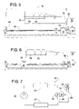
- FIG. 5 is a schematic diagram of the system of FIG. 1 but showing the stepper motor suddenly reversing direction as the driven member encounters the travel limit.
- FIG. 6 is a schematic diagram similar to FIG. 5 but showing the driven member correcting its course after first reversing direction.
- FIG. 7 is a schematic diagram of a refrigerant system employing the stepper motor system of FIGS. 1-6 .
- a stepper motor 10 shown in FIGS. 1-7 , is shown driving a driven member 12 over a travel range 14 .
- Stepper motor 10 is schematically illustrated to represent any electromechanical device that uses discrete electrical pulses in a certain sequence to create rotating electrical fields that drive a magnetic rotor in controlled rotational steps.
- the subject invention is particularly suited for permanent magnet stepper motors; however, the invention might also apply to other types of stepper motors as well.
- the structure and function of permanent magnet stepper motors and other types of stepper motors are well known to those of ordinary skill in the art.
- motor 10 rotates a lead screw 16 that moves member 12 to the right or left depending on the motor's direction of rotation.
- a lead screw is shown coupling motor 10 to driven member 12 , it should be appreciated by those of ordinary skill in the art that any suitable mechanism (rotational, linear, pivotal linkage, etc.) could be used to couple a stepper motor to a driven member.
- Driven member 12 is schematically illustrated to represent any structure moved in translation and/or rotation by a stepper motor.
- An example of driven member 12 includes, but is not limited to, a valve plug or spool of an electronic expansion valve 18 used in a refrigerant system 20 , wherein system 20 comprises a refrigerant compressor 22 , a condenser 24 and an evaporator 26 .
- system 20 comprises a refrigerant compressor 22 , a condenser 24 and an evaporator 26 .
- a microcomputer controller 32 In response to an input signal 28 from a sensor 30 that senses an operating condition of system 20 , a microcomputer controller 32 provides an output signal 34 that commands stepper motor 10 to adjust the opening of valve 18 .
- controller 32 commands motor 10 to drive driven member 12 from its current position to a predetermined travel limit 36 that defines a reference point.
- stepper motor 10 drives driven member 12 in ever-shorter segments toward travel limit 36 , wherein a first segment 38 is less than 1 ⁇ 3 of the total travel range 14 so that a 3-times speed reversal is unable to move driven member 12 all the way back to an opposite end stop 40 .
- the calibration for example, might proceed as shown in FIGS. 1-4 .
- driven member 12 is shown at an operational point 42 that is a travel distance 44 away from travel limit 36 .
- Controller 32 first commands motor 10 to move driven member 12 from point 42 to travel limit 36 and do so over first period 38 that is, for example, 25% the length of range 14 or certainly less than 1 ⁇ 3 of range 14 .
- a vertical axis 46 represents the speed of driven member 12
- a horizontal axis 48 represents the driven member's position along range 14 .
- a positive slope 50 indicates that driven member 12 is accelerating
- a negative slope 52 represents deceleration.
- a series of dashes represents a plurality of steps 54 , wherein each step is the smallest discrete increment that member 12 can be driven controllably by stepper motor 10 . It should be noted that the acceleration and deceleration of driven member 12 occurs over multiple steps 54 . It should also be noted that the plotted speed/position profiles are not necessarily to scale.
- FIG. 2 shows driven member 12 having reached a position 56 at which point controller 32 commands motor 10 to reaccelerate driven member 12 to move member 12 over a second period 58 that is shorter than first period 38 .
- Second period 58 could be 75% the length of first period 38 .
- controller 32 it is preferable for controller 32 to command motor 10 to actually stop driven member 12 momentarily at position 56 so that member 12 periodically pauses between periods of movement. The pause, however, is relatively brief and preferably consumes less time than each period of acceleration or deceleration.
- FIG. 3 shows driven member 12 having reached a position 60 at which point controller 32 once again commands motor 10 to reaccelerate driven member 12 to travel over a third period 62 toward travel limit 36 .
- Driven member 12 thus travels over a plurality of periods of relatively fast, continuous movement (e.g., periods 38 ′, 58 ′ and 62 ′) each separated by a period of slower movement (e.g., periods 64 , 66 and 68 ).
- Third period 62 is shorter than second period 58 ; for example, period 62 could be 75% the length of second period 58 .
- the total number of periods (e.g., periods 38 , 58 , 62 , etc.) can be more or less than the number shown, and in some cases, the longer periods, such as periods 38 , 58 and 62 , will be sufficient to move member 12 all the way over to position 36 without member 12 ever having to move in discrete steps 70 at the very end of the approach.
- FIG. 4 shows driven member 12 having reached travel limit 36 at which point controller 32 can re-establish the location of the reference point defined by limit 36 .
- FIGS. 5 and 6 illustrate perhaps a worst-case scenario where a calibration process begins with driven member 12 being at an operational point 72 that is quite close to travel limit 36 , and a sudden 3-times speed reversal 74 occurs within a first period of the calibration. The speed reversal moves driven member 12 back to a position 76 that might be just short of opposite limit 40 . Nonetheless, controller 32 subsequently commands motor 10 to move driven member 12 toward travel limit 36 in a sequential step-like manner similar to that described with reference to FIGS. 1-4 .
- the invention can be characterized as a method of calibrating a stepper motor wherein the motor has a characteristic number of positions before a motor position cycle is repeated and wherein the motor moves a device over a known range of steps.
- the method comprises the steps of: initializing a calibration interval to be greater than the known range of steps; setting a next step value equal to ((1/number of positions)*calibration interval); driving the motor a number of steps equal to the next step value; determining if the calibration interval is less than a stop value; if yes, commencing a stopping sequence; or if no, modifying the calibration interval to equal (((number of positions ⁇ 1)/number of positions)*calibration interval), and returning to the setting step.
Abstract
Description
Claims (27)
Priority Applications (5)
| Application Number | Priority Date | Filing Date | Title |
|---|---|---|---|
| US11/818,821 US7656115B2 (en) | 2007-06-15 | 2007-06-15 | Calibrating stepper motor by driving fractional ranges |
| PCT/US2008/006502 WO2008156541A2 (en) | 2007-06-15 | 2008-05-21 | Calibrating stepper motor by driving fractional ranges |
| CA2688839A CA2688839C (en) | 2007-06-15 | 2008-05-21 | Calibrating stepper motor by driving fractional ranges |
| CN2008800199770A CN101689824B (en) | 2007-06-15 | 2008-05-21 | Calibrating stepper motor by driving fractional ranges |
| EP08754615.6A EP2158674B1 (en) | 2007-06-15 | 2008-05-21 | Calibrating stepper motor by driving fractional ranges |
Applications Claiming Priority (1)
| Application Number | Priority Date | Filing Date | Title |
|---|---|---|---|
| US11/818,821 US7656115B2 (en) | 2007-06-15 | 2007-06-15 | Calibrating stepper motor by driving fractional ranges |
Publications (2)
| Publication Number | Publication Date |
|---|---|
| US20080309280A1 US20080309280A1 (en) | 2008-12-18 |
| US7656115B2 true US7656115B2 (en) | 2010-02-02 |
Family
ID=39967995
Family Applications (1)
| Application Number | Title | Priority Date | Filing Date |
|---|---|---|---|
| US11/818,821 Active 2028-10-02 US7656115B2 (en) | 2007-06-15 | 2007-06-15 | Calibrating stepper motor by driving fractional ranges |
Country Status (5)
| Country | Link |
|---|---|
| US (1) | US7656115B2 (en) |
| EP (1) | EP2158674B1 (en) |
| CN (1) | CN101689824B (en) |
| CA (1) | CA2688839C (en) |
| WO (1) | WO2008156541A2 (en) |
Cited By (1)
| Publication number | Priority date | Publication date | Assignee | Title |
|---|---|---|---|---|
| US20210156596A1 (en) * | 2019-11-27 | 2021-05-27 | Carrier Corporation | System and method for positioning a slider of a reversing valve |
Families Citing this family (6)
| Publication number | Priority date | Publication date | Assignee | Title |
|---|---|---|---|---|
| GB0908113D0 (en) * | 2009-05-12 | 2009-06-24 | Goodrich Control Sys Ltd | Metering valve control |
| DE112011105588B4 (en) * | 2011-09-01 | 2021-01-07 | Toyota Jidosha Kabushiki Kaisha | Secondary battery with non-aqueous electrolyte |
| CN102629116A (en) * | 2012-04-12 | 2012-08-08 | 曾毅祺 | Control circuit and fluid output control device |
| KR101838505B1 (en) * | 2015-10-13 | 2018-03-14 | 현대자동차주식회사 | Vehicle cluster gauge system and method for calibrating the same |
| CN109412476B (en) * | 2018-10-10 | 2020-07-24 | 常州宝龙电机有限公司 | Stepping motor position detection and control method and device |
| FR3122467B1 (en) * | 2021-04-29 | 2023-04-14 | Valeo Systemes Thermiques | Method for calibrating an electronic expansion valve within a thermal management device of a motor vehicle |
Citations (29)
| Publication number | Priority date | Publication date | Assignee | Title |
|---|---|---|---|---|
| US4523436A (en) | 1983-12-22 | 1985-06-18 | Carrier Corporation | Incrementally adjustable electronic expansion valve |
| FR2567660A1 (en) | 1984-07-11 | 1986-01-17 | Harmand Jean Paul | Device for automatic control of the movements of the axes of rotation of mountings of optical instruments for amateur astronomy and method employing this device. |
| US4593881A (en) | 1982-10-27 | 1986-06-10 | System Homes Company, Ltd. | Electronic expansion valve |
| US4628499A (en) * | 1984-06-01 | 1986-12-09 | Scientific-Atlanta, Inc. | Linear servoactuator with integrated transformer position sensor |
| US5260811A (en) * | 1989-08-18 | 1993-11-09 | Minolta Camera Kabushiki Kaisha | Image scanning apparatus having motor operating under improved drive control |
| US5481187A (en) * | 1991-11-29 | 1996-01-02 | Caterpillar Inc. | Method and apparatus for determining the position of an armature in an electromagnetic actuator |
| US5485070A (en) * | 1992-09-29 | 1996-01-16 | Canon Kabushiki Kaisha | Stepping-motor driving system |
| US5665897A (en) | 1996-08-09 | 1997-09-09 | Delco Electronics Corporation | Method of calibrating and zeroing stepper motor gauges |
| US5942872A (en) | 1995-06-16 | 1999-08-24 | Moto Meter Gmbh | Method of controlling a stepping motor |
| US20010017824A1 (en) * | 1997-02-27 | 2001-08-30 | Matsushita Electric Industrial Co., Ltd. | Stepping motor control method and disk drive apparatus |
| US6301441B1 (en) * | 1999-09-13 | 2001-10-09 | Asahi Kogaku Kogyo Kabushiki Kaisha | Lens driving device |
| US20020050898A1 (en) * | 2000-07-28 | 2002-05-02 | Johan Olsson | Method and arrangement for determining the position of an electromagnetic actuator |
| US6462497B1 (en) * | 1998-09-11 | 2002-10-08 | Skf Engineering & Research Centre B.V. | Method and apparatus for energizing rotation-translation converters |
| US20030102828A1 (en) * | 2001-11-13 | 2003-06-05 | Hiromi Kusakabe | Driving device for oscillatory actuator |
| US20030102838A1 (en) | 2000-02-29 | 2003-06-05 | Fyfe David Mcintyre | Instrument reference system |
| US20030214265A1 (en) | 2002-05-20 | 2003-11-20 | Vanderzee Joel C. | Stepper driver system with current feedback |
| US6853162B2 (en) | 2002-12-05 | 2005-02-08 | Visteon Global Technologies, Inc. | Re-zeroing of a stepper motor without noise or movement |
| US20050061090A1 (en) * | 2003-08-21 | 2005-03-24 | Klaus Oberndorfer | System and method for the detection of a defect in a drive belt |
| US20060055360A1 (en) | 2004-09-14 | 2006-03-16 | Reiter Thomas J | Open loop motor parking method and system |
| US20060113933A1 (en) * | 2004-06-04 | 2006-06-01 | The Boeing Company | Fault-tolerant electromechanical actuator having a torque sensing control system |
| US20070040529A1 (en) * | 2005-08-19 | 2007-02-22 | Smc Corporation Of America | Stepping motor control system and method for controlling a stepping motor using closed and open loop controls |
| US20070098373A1 (en) * | 2003-12-01 | 2007-05-03 | Koichi Saito | Dc motor drive unit |
| US20070247092A1 (en) * | 2006-02-14 | 2007-10-25 | Makoto Komatsu | Brushless-motor driving control device, image reading apparatus, and image forming apparatus |
| US20070280082A1 (en) * | 2004-03-31 | 2007-12-06 | Kazuo Takahashi | Optical Pickup Transfer Apparatus |
| US20070296804A1 (en) * | 2006-06-26 | 2007-12-27 | Yamaha Corporation | Optical Disk Image Drawing Method and Optical Disk Apparatus, and Optical Disk Recording Medium |
| US20080002015A1 (en) * | 2006-06-26 | 2008-01-03 | Yamaha Corporation | Optical Disk Image Drawing Method |
| US20080106293A1 (en) * | 2004-12-21 | 2008-05-08 | Advantest Corporation | Drive Method And Drive Circuit Of Peltier Element, Attaching Structure Of Peltier Module And Electronic Device Handling Apparatus |
| US7460444B2 (en) * | 2004-04-28 | 2008-12-02 | Nec Electronics Corporation | Optical disk drive and method for controlling sled motor within optical disk drive |
| US20090148138A1 (en) * | 2007-11-28 | 2009-06-11 | Sciuto Marcello | Method for controlling an electric motor by using the PWM Technique |
Family Cites Families (2)
| Publication number | Priority date | Publication date | Assignee | Title |
|---|---|---|---|---|
| US4215302A (en) * | 1978-01-26 | 1980-07-29 | Mcc Associates | Control system for stepping motors, a method of operating stepping motors, and a method for selecting current patterns for stepping motors |
| US5508596A (en) * | 1993-10-07 | 1996-04-16 | Omax Corporation | Motion control with precomputation |
-
2007
- 2007-06-15 US US11/818,821 patent/US7656115B2/en active Active
-
2008
- 2008-05-21 WO PCT/US2008/006502 patent/WO2008156541A2/en active Application Filing
- 2008-05-21 EP EP08754615.6A patent/EP2158674B1/en active Active
- 2008-05-21 CN CN2008800199770A patent/CN101689824B/en active Active
- 2008-05-21 CA CA2688839A patent/CA2688839C/en not_active Expired - Fee Related
Patent Citations (33)
| Publication number | Priority date | Publication date | Assignee | Title |
|---|---|---|---|---|
| US4593881A (en) | 1982-10-27 | 1986-06-10 | System Homes Company, Ltd. | Electronic expansion valve |
| US4523436A (en) | 1983-12-22 | 1985-06-18 | Carrier Corporation | Incrementally adjustable electronic expansion valve |
| US4628499A (en) * | 1984-06-01 | 1986-12-09 | Scientific-Atlanta, Inc. | Linear servoactuator with integrated transformer position sensor |
| FR2567660A1 (en) | 1984-07-11 | 1986-01-17 | Harmand Jean Paul | Device for automatic control of the movements of the axes of rotation of mountings of optical instruments for amateur astronomy and method employing this device. |
| US5260811A (en) * | 1989-08-18 | 1993-11-09 | Minolta Camera Kabushiki Kaisha | Image scanning apparatus having motor operating under improved drive control |
| US5600237A (en) * | 1991-11-29 | 1997-02-04 | Caterpillar Inc. | Method and apparatus for determining the position of an armature in an electromagnetic actuator by measuring the driving voltage frequency |
| US5578904A (en) * | 1991-11-29 | 1996-11-26 | Caterpillar Inc. | Method and apparatus for determining the position of an armature of an electromagnetic actuator in response to the magnitude and time derivative of the actuator coil current |
| US5481187A (en) * | 1991-11-29 | 1996-01-02 | Caterpillar Inc. | Method and apparatus for determining the position of an armature in an electromagnetic actuator |
| US5485070A (en) * | 1992-09-29 | 1996-01-16 | Canon Kabushiki Kaisha | Stepping-motor driving system |
| US5942872A (en) | 1995-06-16 | 1999-08-24 | Moto Meter Gmbh | Method of controlling a stepping motor |
| US5665897A (en) | 1996-08-09 | 1997-09-09 | Delco Electronics Corporation | Method of calibrating and zeroing stepper motor gauges |
| US20010017824A1 (en) * | 1997-02-27 | 2001-08-30 | Matsushita Electric Industrial Co., Ltd. | Stepping motor control method and disk drive apparatus |
| US20050083800A1 (en) * | 1997-02-27 | 2005-04-21 | Matsushita Electric Industrial Co., Ltd. | Disk drive apparatus |
| US20050047290A1 (en) * | 1997-02-27 | 2005-03-03 | Matsushita Electric Industrial Co., Ltd. | Stepping motor controlling method and disk apparatus |
| US6462497B1 (en) * | 1998-09-11 | 2002-10-08 | Skf Engineering & Research Centre B.V. | Method and apparatus for energizing rotation-translation converters |
| US6301441B1 (en) * | 1999-09-13 | 2001-10-09 | Asahi Kogaku Kogyo Kabushiki Kaisha | Lens driving device |
| US20030102838A1 (en) | 2000-02-29 | 2003-06-05 | Fyfe David Mcintyre | Instrument reference system |
| US20020050898A1 (en) * | 2000-07-28 | 2002-05-02 | Johan Olsson | Method and arrangement for determining the position of an electromagnetic actuator |
| US20030102828A1 (en) * | 2001-11-13 | 2003-06-05 | Hiromi Kusakabe | Driving device for oscillatory actuator |
| US20030214265A1 (en) | 2002-05-20 | 2003-11-20 | Vanderzee Joel C. | Stepper driver system with current feedback |
| US6853162B2 (en) | 2002-12-05 | 2005-02-08 | Visteon Global Technologies, Inc. | Re-zeroing of a stepper motor without noise or movement |
| US20050061090A1 (en) * | 2003-08-21 | 2005-03-24 | Klaus Oberndorfer | System and method for the detection of a defect in a drive belt |
| US20070098373A1 (en) * | 2003-12-01 | 2007-05-03 | Koichi Saito | Dc motor drive unit |
| US20070280082A1 (en) * | 2004-03-31 | 2007-12-06 | Kazuo Takahashi | Optical Pickup Transfer Apparatus |
| US7460444B2 (en) * | 2004-04-28 | 2008-12-02 | Nec Electronics Corporation | Optical disk drive and method for controlling sled motor within optical disk drive |
| US20060113933A1 (en) * | 2004-06-04 | 2006-06-01 | The Boeing Company | Fault-tolerant electromechanical actuator having a torque sensing control system |
| US20060055360A1 (en) | 2004-09-14 | 2006-03-16 | Reiter Thomas J | Open loop motor parking method and system |
| US20080106293A1 (en) * | 2004-12-21 | 2008-05-08 | Advantest Corporation | Drive Method And Drive Circuit Of Peltier Element, Attaching Structure Of Peltier Module And Electronic Device Handling Apparatus |
| US20070040529A1 (en) * | 2005-08-19 | 2007-02-22 | Smc Corporation Of America | Stepping motor control system and method for controlling a stepping motor using closed and open loop controls |
| US20070247092A1 (en) * | 2006-02-14 | 2007-10-25 | Makoto Komatsu | Brushless-motor driving control device, image reading apparatus, and image forming apparatus |
| US20070296804A1 (en) * | 2006-06-26 | 2007-12-27 | Yamaha Corporation | Optical Disk Image Drawing Method and Optical Disk Apparatus, and Optical Disk Recording Medium |
| US20080002015A1 (en) * | 2006-06-26 | 2008-01-03 | Yamaha Corporation | Optical Disk Image Drawing Method |
| US20090148138A1 (en) * | 2007-11-28 | 2009-06-11 | Sciuto Marcello | Method for controlling an electric motor by using the PWM Technique |
Non-Patent Citations (1)
| Title |
|---|
| "Spontaneous Speed Reversals in Stepper Motors"; Marc Bodson, Jeffrey S. Sato and Stephen R. Silver; IEEE Transactions on Control Systems Tech., vol. 14, No. 2, Mar. 2006. |
Cited By (1)
| Publication number | Priority date | Publication date | Assignee | Title |
|---|---|---|---|---|
| US20210156596A1 (en) * | 2019-11-27 | 2021-05-27 | Carrier Corporation | System and method for positioning a slider of a reversing valve |
Also Published As
| Publication number | Publication date |
|---|---|
| US20080309280A1 (en) | 2008-12-18 |
| CN101689824B (en) | 2012-05-30 |
| CA2688839C (en) | 2014-01-21 |
| WO2008156541A2 (en) | 2008-12-24 |
| CA2688839A1 (en) | 2008-12-24 |
| WO2008156541A3 (en) | 2009-03-19 |
| CN101689824A (en) | 2010-03-31 |
| EP2158674B1 (en) | 2019-03-06 |
| EP2158674A2 (en) | 2010-03-03 |
Similar Documents
| Publication | Publication Date | Title |
|---|---|---|
| US7656115B2 (en) | Calibrating stepper motor by driving fractional ranges | |
| EP1710904B1 (en) | Brushless DC motor control | |
| WO2018155332A1 (en) | Shift range control device | |
| US10690243B2 (en) | Range switching device for automatic transmission and switching method therefor | |
| US10008963B2 (en) | Position control device | |
| CN108345269B (en) | Control device, control system, and recording medium | |
| JP6921616B2 (en) | Controls, optics, control methods, and programs | |
| US9059654B2 (en) | Motor driving device, and motor control method | |
| US8994303B2 (en) | Method and device for driving brushless direct-current motor during displacement of actuating element | |
| US8378617B2 (en) | Method of controlling current of high-speed switched reluctance motor | |
| CN110768595A (en) | Control method and electric valve | |
| US11817801B2 (en) | Motor speed controller and speed control system | |
| EP3847744A1 (en) | An actuator with an electric motor and a method of controlling the electric motor to maintain a current position | |
| JP6747302B2 (en) | Vacuum valve | |
| KR100386279B1 (en) | Driving control method for reciprocating compressor | |
| KR100393807B1 (en) | Driving comtrol apparatus for reciprocating compressor | |
| JP2000284805A (en) | Feedback controller | |
| KR100386280B1 (en) | Driving control method for reciprocating compressor | |
| JP2000293234A (en) | Motor control gain switching method | |
| CN114337404A (en) | DC motor control method, air conditioner and computer readable storage medium | |
| KR100944120B1 (en) | System and method of controlling location of a member | |
| CN116332045A (en) | Control method, storage medium, controller and control system for steering valve | |
| CN117661959A (en) | Control method and system for electric tail gate | |
| WO1987002097A1 (en) | Rotational speed controller for engine | |
| KR100414117B1 (en) | Driving control method for reciprocating compressor |
Legal Events
| Date | Code | Title | Description |
|---|---|---|---|
| AS | Assignment |
Owner name: AMERICAN STARDARD INTERNATIONAL INC., NEW YORK Free format text: ASSIGNMENT OF ASSIGNORS INTEREST;ASSIGNOR:VANDERZEE, JOEL C.;REEL/FRAME:019507/0573 Effective date: 20070615 Owner name: AMERICAN STARDARD INTERNATIONAL INC.,NEW YORK Free format text: ASSIGNMENT OF ASSIGNORS INTEREST;ASSIGNOR:VANDERZEE, JOEL C.;REEL/FRAME:019507/0573 Effective date: 20070615 |
|
| AS | Assignment |
Owner name: TRANE INTERNATIONAL INC., NEW YORK Free format text: CHANGE OF NAME;ASSIGNOR:AMERICAN STANDARD INTERNATIONAL INC.;REEL/FRAME:020733/0970 Effective date: 20071128 Owner name: TRANE INTERNATIONAL INC.,NEW YORK Free format text: CHANGE OF NAME;ASSIGNOR:AMERICAN STANDARD INTERNATIONAL INC.;REEL/FRAME:020733/0970 Effective date: 20071128 |
|
| STCF | Information on status: patent grant |
Free format text: PATENTED CASE |
|
| FPAY | Fee payment |
Year of fee payment: 4 |
|
| FPAY | Fee payment |
Year of fee payment: 8 |
|
| MAFP | Maintenance fee payment |
Free format text: PAYMENT OF MAINTENANCE FEE, 12TH YEAR, LARGE ENTITY (ORIGINAL EVENT CODE: M1553); ENTITY STATUS OF PATENT OWNER: LARGE ENTITY Year of fee payment: 12 |