US7657391B2 - Electromagnetically detecting thin resistive bodies in shallow water and terrestrial environments - Google Patents
Electromagnetically detecting thin resistive bodies in shallow water and terrestrial environments Download PDFInfo
- Publication number
- US7657391B2 US7657391B2 US11/457,623 US45762306A US7657391B2 US 7657391 B2 US7657391 B2 US 7657391B2 US 45762306 A US45762306 A US 45762306A US 7657391 B2 US7657391 B2 US 7657391B2
- Authority
- US
- United States
- Prior art keywords
- data
- measurements
- electric field
- magnetic field
- polarization
- Prior art date
- Legal status (The legal status is an assumption and is not a legal conclusion. Google has not performed a legal analysis and makes no representation as to the accuracy of the status listed.)
- Expired - Fee Related, expires
Links
Images


Classifications
-
- G—PHYSICS
- G01—MEASURING; TESTING
- G01V—GEOPHYSICS; GRAVITATIONAL MEASUREMENTS; DETECTING MASSES OR OBJECTS; TAGS
- G01V3/00—Electric or magnetic prospecting or detecting; Measuring magnetic field characteristics of the earth, e.g. declination, deviation
- G01V3/12—Electric or magnetic prospecting or detecting; Measuring magnetic field characteristics of the earth, e.g. declination, deviation operating with electromagnetic waves
-
- G—PHYSICS
- G01—MEASURING; TESTING
- G01V—GEOPHYSICS; GRAVITATIONAL MEASUREMENTS; DETECTING MASSES OR OBJECTS; TAGS
- G01V3/00—Electric or magnetic prospecting or detecting; Measuring magnetic field characteristics of the earth, e.g. declination, deviation
- G01V3/08—Electric or magnetic prospecting or detecting; Measuring magnetic field characteristics of the earth, e.g. declination, deviation operating with magnetic or electric fields produced or modified by objects or geological structures or by detecting devices
- G01V3/083—Controlled source electromagnetic [CSEM] surveying
-
- Y—GENERAL TAGGING OF NEW TECHNOLOGICAL DEVELOPMENTS; GENERAL TAGGING OF CROSS-SECTIONAL TECHNOLOGIES SPANNING OVER SEVERAL SECTIONS OF THE IPC; TECHNICAL SUBJECTS COVERED BY FORMER USPC CROSS-REFERENCE ART COLLECTIONS [XRACs] AND DIGESTS
- Y02—TECHNOLOGIES OR APPLICATIONS FOR MITIGATION OR ADAPTATION AGAINST CLIMATE CHANGE
- Y02A—TECHNOLOGIES FOR ADAPTATION TO CLIMATE CHANGE
- Y02A90/00—Technologies having an indirect contribution to adaptation to climate change
- Y02A90/30—Assessment of water resources
Definitions
- the invention generally relates to electromagnetically detecting thin resistive bodies in shallow water and terrestrial environments.
- One technique to locate an oil reservoir beneath the sea floor is to measure electromagnetic fields that are produced by a controlled electromagnetic source. More specifically, in a technique called controlled source electromagnetic (CSEM) surveying, an electrical dipole (i.e., a controlled electromagnetic source) may be towed by a surface vessel a short distance above the sea floor. Measurements of the resulting electric and/or magnetic fields are then measured using receivers, which may be deployed, for example, on the sea floor. Ideally, the presence of a thin resistive layer, such as an oil reservoir, affects the measured electric and magnetic fields in a way that can be detected from the measured data.
- CSEM controlled source electromagnetic
- CSEM surveying typically is limited to deep water, as a phenomenon called an “air wave effect” (as referred to in the literature) currently limits the use of CSEM surveying in shallow water environments. More specifically, the electromagnetic fields that are produced by the electric dipole interact with the air-sea interface to generate electromagnetic energy, or “air waves,” which diffuse from the sea surface down to the receiver. For shallow water, the air waves dominate the measured electromagnetic data so that the presence of a thin resistive body may not be readily discernible from the data. Similar challenges limit the application of CSEM surveying to terrestrial environments.
- a technique in an embodiment of the invention, includes performing first electromagnetic field measurements to obtain a first set of data and performing second electromagnetic field measurements to obtain a second set of data.
- the first set of data is relatively sensitive to an effect caused by an air layer boundary and is relatively insensitive to the presence of a resistive body.
- the second set of data is relatively sensitive to the effect and is relatively sensitive to the presence of the resistive body.
- the technique includes combining the first and second sets of data to generate a third set of data, which is relatively insensitive to the effect and is relatively sensitive to the presence of the resistive body.
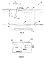
- FIG. 1 is an illustration of a system for obtaining controlled source electromagnetic field measurements according to an embodiment of the invention.
- FIGS. 2 , 5 and 6 are flow diagrams depicting techniques to desensitize controlled source electromagnetic survey data to the air wave effect according to embodiments of the invention.
- FIG. 3 is an illustration of the relative orientations of an electric dipole source and receivers for an inline measurement configuration according to an embodiment of the invention.
- FIG. 4 is an illustration of the relative orientations of an electric dipole source and receivers for a crossline measurement configuration according to an embodiment of the invention.
- FIG. 7 is a table depicting a summary of marine model, source and receiver parameters of an exemplary survey according to an embodiment of the invention.
- FIG. 8 depicts electric fields obtained in connection with the survey summarized in FIG. 7 according to an embodiment of the invention.
- FIG. 9 depicts impedances obtained in connection with the survey summarized in FIG. 7 according to an embodiment of the invention.
- FIG. 10 is a table summarizing a land model, source and receiver parameters of an exemplary terrestrial crosshole electromagnetic survey according to an embodiments of the invention.
- FIG. 11 depicts electric fields obtained in connection with the survey summarized in FIG. 10 according to an embodiment of the invention.
- FIG. 12 depicts impedances obtained in connection with the survey summarized in FIG. 10 according to an embodiment of the invention.
- FIG. 13 depicts a computer according to an embodiment of the invention.
- a system 20 that is depicted in FIG. 1 may be used for purposes of performing a controlled source electromagnetic (CSEM) survey in relatively shallow water.
- the survey is useful for locating a thin resistive body, such as the exemplary resistive body 21 that is depicted in FIG. 1 .
- the survey uses a controlled towed electromagnetic dipole 24 , which may be towed from a surface ship 22 , for example.
- the electric dipole 24 generates electromagnetic fields, which are measured using receivers 30 (one receiver 30 being depicted in FIG. 1 ) that are located on a seabed floor 26 .
- the resistive body 21 generally produces stronger electric fields with increasing source-receiver offset than if the resistive body is absent.
- the electric field that is measured via the CSEM survey may be used as an indicator for purposes of locating thin resistive bodies, such as hydrocarbon reservoirs, gas reservoirs, water aquifers, etc.
- a potential challenge associated with CSEM surveying is that relatively shallow water may produce an air wave effect due to a boundary between the sea surface 38 and the air.
- two sets of measurements are collected using different survey configurations. These measurements are then combined to produce a set of measurement data, which is relatively insensitive to the air wave effect.
- a CSEM survey technique 40 includes performing first electromagnetic field measurements to obtain a first set of data, which is relatively sensitive to the air wave effect and is relatively insensitive to resistive bodies, pursuant to block 42 .
- second electromagnetic field measurements are performed (block 44 ) to obtain a second set of data, which is relatively sensitive to the air wave effect and is also relatively sensitive to resistive bodies.
- both sets of measurements are sensitive to the air wave effect, and only the second set of data is sensitive to resistive bodies.
- the first and second sets of data may be combined (block 46 ) in a way that effectively cancels out the air wave effect.
- This combination described further below, generates a third set of data, which is insensitive to the air wave effect and is sensitive to resistive bodies.
- measurement-based data is created, which has an enhanced sensitivity to the resistive bodies.
- the electric dipole 24 is towed at a depth z below the sea surface 38 .
- a particular receiver such as the depicted receiver 30 , may be located at a depth h below the sea surface 38 and may be separated from the electric dipole 24 by a distance R.
- the electric and magnetic fields at the receiver may be approximately expressed as follows: E,H ⁇ P 0 +P 1 +L, Eq. 1 where “P 0 ” represents a direct wave response at the receiver, which is produced by the electric dipole 24 . It is assumed that the direct wave is produced in a medium of uniform conductivity, corresponding to that of the earth.
- the sea water has a uniform conductivity of “ ⁇ sw, ” and “P 1 ” represents a modified image term, which is conceptually generated by a second electric dipole source also located in a earth of uniform conductivity but is positioned a distance approximately equal to 2z above the true electric dipole source 24 .
- the term “L” in Eq. 1 represents the air effect, or the lateral electromagnetic field, which is attenuated as it travels straight upward from the source to the air-sea water interface, travels laterally along the interface with the amplitude decreasing only through geometrical spreading and then is attenuated as it travels down from the air-sea water interface to the receiver 30 .
- the component “L” in Eq. 1 represents the air wave effect, which may dominate and thus obscure, the measured electric or magnetic fields, if not for the techniques that are discussed herein.
- two sets of electromagnetic field measurements that derived with different polarizations are combined. More specifically, in accordance with some embodiments of the invention, two CSEM surveys are performed using two different survey configurations: an inline survey configuration in which the electric dipole 24 is in line with the receiver 30 (and other such receivers 30 ); and a broadside, or crossline, survey configuration in which the electric dipole 24 is orthogonal with respect to the orientation of the receiver 30 (and other such receivers 30 ).
- the inline survey configuration is relatively sensitive both to resistive bodies and to the air wave effect
- the crossline survey configuration is also relatively sensitive to the air wave effect but is relatively insensitive to resistive bodies. Therefore, in accordance with some embodiments of the invention, the electric fields (or alternatively, the magnetic fields, if magnetic field measurements are used) that are measured via the crossline configuration are subtracted from the electric fields that are measured via the inline configuration to derive electric fields that are relatively more sensitive to the resistive bodies and relatively less sensitive to the air wave effect (as compared to the electric fields derived from the inline or crossline configuration only).
- FIG. 3 depicts the relative orientations of the electric dipole 24 and the receivers 30 for the inline survey configuration in accordance with some embodiments of the invention.
- a main flux path 60 of the electric dipole 24 extends along the longitudinal axis of the electric dipole 24 and is aligned with the linear configuration of the receivers 30 for the inline configuration.
- the main flux path 60 is generally orthogonal to the line along which the receivers 30 extend, as depicted in FIG. 4 .
- the inline survey configuration measures a lateral wave L il , which has the following form:
- the crossline configuration measures a lateral wave L cl , which may be expressed as follows:
- Eqs. 2, 3 and 4 depict the lateral waves L il and L cl when electric fields are measured.
- magnetic fields may also be measured and processed in a similar manner, in accordance with other embodiments of the invention.
- E DIFF the resultant electromagnetic field
- a CSEM survey-based technique 100 may generally be used to produce electric field data, which is sensitive to resistive bodies and relatively de-sensitive to the air wave effect.
- inline CSEM survey measurements are performed (block 102 ) to obtain inline electric field measurements and crossline CSEM survey measurements are also performed (block 104 ) to obtain crossline electric field measurements.
- the crossline electric field measurements are then subtracted (block 106 ) from the inline electric field measurements (after the inline electric field measurements are multiplied by two) to generate a calculated electric field that is not generally not sensitive to the air wave effect.
- the technique 100 is relatively more accurate if the two data sets with different polarizations are obtained such that the measurements occupy the same position simultaneously. However, if the two data sets are collected at different times, then the technique 100 may be susceptible to positioning errors. Orientation uncertainties in both the source and the receiver may introduce additional error.
- an inline impedance Z il E x /H y , Eq. 6 where “E x ” represents the component of the electric field, which was measured in the x direction in the inline survey configuration; and “H y ” represents the magnitude of the magnetic field in the y direction, which was obtained in the inline survey configuration.
- Positioning errors may further be minimized by rotating the electric and magnetic field data prior to calculation of the impedance to the minimum and maximum of the polarization ellipses.
- Z DIFF Z il ⁇ Z cl , Eq. 8 Note that in the impedance calculation, the factor of two is dropped out due to the normalization effect of the impedance.
- the Z DIFF impedance may thus be used as an indicator of a resistive body.
- a technique 120 that is based on impedances may be used to detect a resistive body.
- inline measurements are made to obtain inline electric and magnetic field measurements, pursuant to block 122 .
- crossline measurements are performed (block 124 ) to obtain crossline electric and magnetic field measurements.
- the electric and magnetic field measurements may then be rotated, pursuant to block 128 , to the minimum and maximum of the polarization ellipses.
- the inline (block 132 ) and the crossline (block 134 ) impedances are then determined.
- the crossline impedances may be subtracted from the inline impedance to generate an impedance that is not subject to the air effect, pursuant to block 136 .
- the differencing methods that are described above also may be used for land-based measurements.
- a marine model includes a thirty meter water layer of electrical resistivity of 0.33 ohm-m, which overlays a half space of electrical resistivity of 0.7 ohm-m. This constitutes the “background” model.
- the “reservoir,” or resistor, model includes a 100 meter thick resistive layer of 20 ohm-m, a depth of 2000 m below the seabed.
- the data was simulated for a horizontal electrical dipole source of unit moment aligned in the x and y directions operating at a frequency of 0.1 Hz, located 15 meters above the seabed. Measurements of the horizontal electric and magnetic fields were taken every 500 meters along the x axis from 500 meters to 15,000 meters relative to the source.
- FIG. 8 depicts the horizontal electric fields that were obtained using the model and the techniques described herein.
- FIG. 8 depicts a plot 212 of the background electric field, a plot 208 of the crossline electric field of the background and a plot 216 of the difference between the inline and crossline backgrounds.
- FIG. 8 also depicts a plot 206 of the measured inline electric field of the reservoir and a plot 209 of the measured crossline reservoir electric field.
- FIG. 8 depicts a plot 214 , which shows a difference between the inline 206 and crossline 209 plots.
- FIG. 9 depicts results if impedances are employed.
- FIG. 9 depicts a plot 220 of the inline background impedance, a plot 242 of the crossline background impedance and a plot 224 of the difference in the inline and crossline background impedances.
- FIG. 9 also depicts a plot 236 of the inline reservoir impedances, a plot 228 of the crossline reservoir impedances and a difference between the inline and crossline reservoir impedances. It is noted that the dynamic range of this plot is much smaller than that of the electric fields of FIG. 8 , as taking the ratio of the electric and magnetic fields normalizes out the effects of geometrical decay and electromagnetic attenuation. Thus, errors due to positioning are minimized. As also noted that there are substantial differences that are within the range of measurability.
- FIG. 10 depicts a table, which summarizes the parameters for a terrestrial model.
- the model employed a half space of the electrical resistivity of 5 ohm-m, which serves as the background.
- the reservoir model includes a 100 meter thick resistive layer of 100 ohm-m at a depth of 2000 meter below the earth's surface.
- Data was simulated for a horizontal electrical dipole source of unit moment aligned in the x and y directions operating at a frequency of 0.8 Hz. Measurements of the horizontal electric and magnetic fields were taken every 500 meters along the x axis from 500 meters to 15,000 meters relative to the source.
- FIG. 11 depicts a plot 300 of the inline background electric field, a plot 302 of the crossline background electric field and a plot 304 illustrating the differences between the inline 300 and crossline 302 plots. Additionally, FIG. 11 depicts a plot 312 of the inline reservoir electric field, a plot 314 of the crossline reservoir electric field and a plot 316 of the difference between the two plots 312 and 314 . As depicted in FIG. 11 , taking the differences of the electric fields accentuates the response caused by the presence of the reservoir.
- FIG. 12 depicts for the terrestrial model a plot 320 of the inline background impedance, a plot 322 of the crossline background impedance and a plot 324 of the difference between the inline 320 and crossline 322 plots.
- FIG. 12 also depicts a plot 328 of the inline reservoir impedance, a plot 330 of the crossline reservoir impedance and a plot 340 of the difference between the inline 328 and crossline 330 impedances.
- a computer 800 may be used for purposes of determining the above-described electric fields, magnetic fields, impedances, rotating the electric and magnetic fields, displaying plots of the electric fields and/or impedances, etc., depending on the particular embodiment of the invention.
- the computer 800 may include, for example, a processor 820 (one or more microprocessors or controllers, as examples) that is coupled to a memory 804 of the computer 800 .
- the memory 804 may be formed partially by semiconductor memory, mass storage, etc., depending on the particular embodiment of the invention.
- the memory 804 stores program instructions 808 that when executed by the processor 820 causes the computer 800 to perform one or more of the functions that are enumerated above.
- the memory 804 may include data 806 , such as electric field data, magnetic field data, impedances, etc., depending on the particular embodiment of the invention.
- the above-described survey data processing techniques may be used in conjunction with deep water (i.e., a water depth in the range of one to three kilometers, for example) surveying, where the source and receivers have relatively large offsets (offsets in the five to fifteen kilometer range, as an example), which may cause the surveying data to be significantly influenced by the air wave effect.
- deep water i.e., a water depth in the range of one to three kilometers, for example
- offsets offsets in the five to fifteen kilometer range, as an example
- the influence of the air wave effect on the survey data depends on a number of factors such as the source-to-receiver offset, the resistivity of the sea bed, the frequency of the electromagnetic energy, used in the surveying, etc.
Abstract
Description
E,H≅P 0 +P 1 +L, Eq. 1
where “P0” represents a direct wave response at the receiver, which is produced by the
where “m” represents the moment of the source, which for an electric dipole is given as the applied current times the length of the source; and “ksw” represents the propagation constant or wave number for sea water, as set forth below:
k sw=√{square root over (2πif μσsw)} Eq. 3
E DIFF=2E IL −E CL, Eq. 5
where “EIL” represents the measured inline electric field, and “ECL” represents the measured crossline electric field. Therefore, the computed EDIFF electromagnetic field magnitude may be used as an indicator for resistive bodies, such as oil reservoirs, gas reservoirs and high quality fresh water aquifers, as just a few examples.
Z il =E x /H y, Eq. 6
where “Ex” represents the component of the electric field, which was measured in the x direction in the inline survey configuration; and “Hy” represents the magnitude of the magnetic field in the y direction, which was obtained in the inline survey configuration.
Z cl =E y /H x, Eq. 7
wherein “Ey” represents the y component of the electric field measured in the crossline survey configuration; and “Hx” represents the x component of the magnetic field measured in the crossline survey configuration.
Z DIFF =Z il −Z cl, Eq. 8
Note that in the impedance calculation, the factor of two is dropped out due to the normalization effect of the impedance. The ZDIFF impedance may thus be used as an indicator of a resistive body.
Claims (19)
Priority Applications (5)
| Application Number | Priority Date | Filing Date | Title |
|---|---|---|---|
| US11/457,623 US7657391B2 (en) | 2006-07-14 | 2006-07-14 | Electromagnetically detecting thin resistive bodies in shallow water and terrestrial environments |
| EP07798068A EP2049921A2 (en) | 2006-07-14 | 2007-06-04 | Electromagnetically detecting thin resistive bodies in shallow water and terrestrial environments |
| PCT/US2007/070322 WO2008008577A2 (en) | 2006-07-14 | 2007-06-04 | Electromagnetically detecting thin resistive bodies in shallow water and terrestrial environments |
| US11/779,440 US7860655B2 (en) | 2006-07-14 | 2007-07-18 | Electromagnetically detecting thin resistive bodies in shallow water and terrestrial environments |
| NO20090659A NO20090659L (en) | 2006-07-14 | 2009-02-11 | Electromagnetic detection of thin resistive bodies in shallow water and land environment |
Applications Claiming Priority (1)
| Application Number | Priority Date | Filing Date | Title |
|---|---|---|---|
| US11/457,623 US7657391B2 (en) | 2006-07-14 | 2006-07-14 | Electromagnetically detecting thin resistive bodies in shallow water and terrestrial environments |
Related Child Applications (1)
| Application Number | Title | Priority Date | Filing Date |
|---|---|---|---|
| US11/779,440 Continuation-In-Part US7860655B2 (en) | 2006-07-14 | 2007-07-18 | Electromagnetically detecting thin resistive bodies in shallow water and terrestrial environments |
Publications (2)
| Publication Number | Publication Date |
|---|---|
| US20080015779A1 US20080015779A1 (en) | 2008-01-17 |
| US7657391B2 true US7657391B2 (en) | 2010-02-02 |
Family
ID=38923980
Family Applications (1)
| Application Number | Title | Priority Date | Filing Date |
|---|---|---|---|
| US11/457,623 Expired - Fee Related US7657391B2 (en) | 2006-07-14 | 2006-07-14 | Electromagnetically detecting thin resistive bodies in shallow water and terrestrial environments |
Country Status (4)
| Country | Link |
|---|---|
| US (1) | US7657391B2 (en) |
| EP (1) | EP2049921A2 (en) |
| NO (1) | NO20090659L (en) |
| WO (1) | WO2008008577A2 (en) |
Cited By (5)
| Publication number | Priority date | Publication date | Assignee | Title |
|---|---|---|---|---|
| US20090309599A1 (en) * | 2008-06-11 | 2009-12-17 | Antoni Marjan Ziolkowski | Method for subsurface electromagnetic surveying using two or more simultaneously actuated electromagnetic sources |
| US20100090701A1 (en) * | 2006-08-25 | 2010-04-15 | Anton Ziolkowski | Marine em exploration |
| US20100135835A1 (en) * | 2006-11-29 | 2010-06-03 | Giacomo Armenio | Variable-displacement vane oil pump |
| US8258791B2 (en) | 2009-01-27 | 2012-09-04 | Mtem Ltd. | Method for subsurface electromagnetic surveying using two or more simultaneously actuated electromagnetic sources to impart electromagnetic signals into a subsurface formation and thereby determining a formation response to each signal |
| US20230296759A1 (en) * | 2020-02-18 | 2023-09-21 | HG Partners, LLC | Continuous-wave radar system for detecting ferrous and non-ferrous metals in saltwater environments |
Families Citing this family (4)
| Publication number | Priority date | Publication date | Assignee | Title |
|---|---|---|---|---|
| US7860655B2 (en) * | 2006-07-14 | 2010-12-28 | Westerngeco L.L.C. | Electromagnetically detecting thin resistive bodies in shallow water and terrestrial environments |
| US7659724B2 (en) * | 2007-03-29 | 2010-02-09 | Westerngeco L.L.C. | Surveying method using an arrangement of plural signal sources |
| US7949470B2 (en) * | 2007-11-21 | 2011-05-24 | Westerngeco L.L.C. | Processing measurement data in a deep water application |
| CN114578435B (en) * | 2022-03-03 | 2023-04-11 | 中国科学院地质与地球物理研究所 | Pressure-bearing bin, seabed electromagnetic acquisition station and acquisition system |
Citations (28)
| Publication number | Priority date | Publication date | Assignee | Title |
|---|---|---|---|---|
| US2652530A (en) | 1948-02-13 | 1953-09-15 | Davidson Stanley | Electromagnetic induction method and apparatus for locating subterranenan electrically conductive bodies |
| US3052836A (en) | 1957-12-24 | 1962-09-04 | Shell Oil Co | Method for marine electrical prospecting |
| US3108220A (en) | 1956-03-08 | 1963-10-22 | Varian Associates | Electromagnetic method and apparatus for geophysical prospecting including means forgenerating an auxiliary flux field to cancel direct coupling between the primary and pick-up coils |
| US3324385A (en) | 1961-11-13 | 1967-06-06 | Donald L Hings | Method and apparatus including movable armature means and transient electromagnetic wave detecting means for locating anomalous bodies |
| US3351936A (en) | 1966-01-10 | 1967-11-07 | Texas Instruments Inc | Method and apparatus for exploring the earth with electromagnetic energy |
| GB2070345A (en) | 1980-02-21 | 1981-09-03 | Superflexit Sa | Dividing box for electrical transmission systems |
| US4617518A (en) | 1983-11-21 | 1986-10-14 | Exxon Production Research Co. | Method and apparatus for offshore electromagnetic sounding utilizing wavelength effects to determine optimum source and detector positions |
| US4633182A (en) | 1983-03-03 | 1986-12-30 | Instytut Gornictwa Naftowego I Gazownictwa | Method and system for direct prospecting of hydrocarbon deposits |
| WO2001000467A1 (en) | 1999-06-24 | 2001-01-04 | Jeffrey John Sharp | Improvements to trailer braking systems |
| WO2002014906A1 (en) | 2000-08-14 | 2002-02-21 | Statoil Asa | Method and apparatus for determining the nature of subterranean reservoirs |
| GB2378511A (en) | 2001-08-07 | 2003-02-12 | Statoil Asa | Locating the boundary of a subterranean reservoir |
| WO2003100467A1 (en) | 2002-05-24 | 2003-12-04 | Statoil Asa | System and method for electromagnetic wavefield resolution |
| WO2004109338A1 (en) | 2003-06-10 | 2004-12-16 | Ohm Limited | Electromagnetic surveying for hydrocarbon reservoirs |
| WO2005010560A1 (en) | 2003-06-26 | 2005-02-03 | Exxonmobil Upstream Research Company | Method for removing air wave effect from offshore frequency domain controlled-source electromagnetic data |
| US20050077902A1 (en) * | 2001-12-07 | 2005-04-14 | Macgregor Lucy M | Electromagnetic surveying for hydrocarbon reservoirs |
| GB2411006A (en) | 2004-02-16 | 2005-08-17 | Ohm Ltd | Electromagnetic surveying for hydrocarbon reservoirs |
| US20060038570A1 (en) | 2002-12-10 | 2006-02-23 | Constable Steven C | System and method for hydrocarbon reservoir monitoring using controlled-source electromagnetic fields |
| US7042801B1 (en) | 2004-02-04 | 2006-05-09 | Seismoelectric Soundings, Inc. | System for geophysical prospecting using induce electrokinetic effect |
| US20060129322A1 (en) * | 2002-07-16 | 2006-06-15 | Macgregor Lucy M | Electromagnetic surveying for hydrocarbon reservoirs |
| GB2423370A (en) * | 2005-02-22 | 2006-08-23 | Ohm Ltd | Electromagnetic surveying for resistive or conductive bodies |
| US20060255809A1 (en) | 2003-03-27 | 2006-11-16 | Johnstad Svein E | Method for monitoring a high resistivity reservoir rock formation |
| US20080015809A1 (en) | 2006-07-14 | 2008-01-17 | Schlumberger Technology Corporation | Electromagnetically Detecting Thin Resistive Bodies in Shallow Water and Terrestrial Environments |
| US20080016817A1 (en) | 2006-07-19 | 2008-01-24 | Zeigler Theodore R | Folding frame system with folding frame elements having diagonal member of variable length |
| US20080061790A1 (en) | 2006-09-12 | 2008-03-13 | Kjt Enterprises, Inc. | Method for combined transient and frequency domain electromagnetic measurements |
| US7359282B2 (en) * | 2003-05-16 | 2008-04-15 | Schlumberger Technology Corporation | Methods and apparatus of source control for borehole seismic |
| US20080091356A1 (en) | 2006-10-12 | 2008-04-17 | Schlumberger Technology Corporation | Computing values for surveying a subterranean structure based on measurements according to different electromagnetic survey techniques |
| US7362101B2 (en) * | 2005-04-27 | 2008-04-22 | The Regents Of The University Of California | Sense optimized MRI RF coil designed with a target field method |
| US20080103700A1 (en) | 2006-10-31 | 2008-05-01 | Schlumberger Technology Corporation | Removing Sea Surface-Related Electromagnetic Fields in Performing an Electromagnetic Survey |
-
2006
- 2006-07-14 US US11/457,623 patent/US7657391B2/en not_active Expired - Fee Related
-
2007
- 2007-06-04 WO PCT/US2007/070322 patent/WO2008008577A2/en active Application Filing
- 2007-06-04 EP EP07798068A patent/EP2049921A2/en not_active Withdrawn
-
2009
- 2009-02-11 NO NO20090659A patent/NO20090659L/en not_active Application Discontinuation
Patent Citations (38)
| Publication number | Priority date | Publication date | Assignee | Title |
|---|---|---|---|---|
| US2652530A (en) | 1948-02-13 | 1953-09-15 | Davidson Stanley | Electromagnetic induction method and apparatus for locating subterranenan electrically conductive bodies |
| US3108220A (en) | 1956-03-08 | 1963-10-22 | Varian Associates | Electromagnetic method and apparatus for geophysical prospecting including means forgenerating an auxiliary flux field to cancel direct coupling between the primary and pick-up coils |
| US3052836A (en) | 1957-12-24 | 1962-09-04 | Shell Oil Co | Method for marine electrical prospecting |
| US3324385A (en) | 1961-11-13 | 1967-06-06 | Donald L Hings | Method and apparatus including movable armature means and transient electromagnetic wave detecting means for locating anomalous bodies |
| US3351936A (en) | 1966-01-10 | 1967-11-07 | Texas Instruments Inc | Method and apparatus for exploring the earth with electromagnetic energy |
| GB2070345A (en) | 1980-02-21 | 1981-09-03 | Superflexit Sa | Dividing box for electrical transmission systems |
| US4633182A (en) | 1983-03-03 | 1986-12-30 | Instytut Gornictwa Naftowego I Gazownictwa | Method and system for direct prospecting of hydrocarbon deposits |
| US4617518A (en) | 1983-11-21 | 1986-10-14 | Exxon Production Research Co. | Method and apparatus for offshore electromagnetic sounding utilizing wavelength effects to determine optimum source and detector positions |
| WO2001000467A1 (en) | 1999-06-24 | 2001-01-04 | Jeffrey John Sharp | Improvements to trailer braking systems |
| WO2002014906A1 (en) | 2000-08-14 | 2002-02-21 | Statoil Asa | Method and apparatus for determining the nature of subterranean reservoirs |
| GB2378511A (en) | 2001-08-07 | 2003-02-12 | Statoil Asa | Locating the boundary of a subterranean reservoir |
| US20070150201A1 (en) * | 2001-12-07 | 2007-06-28 | Terje Eidesmo | Electromagnetic surveying for hydrocarbon reservoirs |
| US7126338B2 (en) * | 2001-12-07 | 2006-10-24 | Statoil Asa | Electromagnetic surveying for hydrocarbon reservoirs |
| US20050077902A1 (en) * | 2001-12-07 | 2005-04-14 | Macgregor Lucy M | Electromagnetic surveying for hydrocarbon reservoirs |
| WO2003100467A1 (en) | 2002-05-24 | 2003-12-04 | Statoil Asa | System and method for electromagnetic wavefield resolution |
| US20060129322A1 (en) * | 2002-07-16 | 2006-06-15 | Macgregor Lucy M | Electromagnetic surveying for hydrocarbon reservoirs |
| US7337064B2 (en) * | 2002-07-16 | 2008-02-26 | University Of Southampton | Electromagnetic surveying for hydrocarbon reservoirs |
| US7109717B2 (en) | 2002-12-10 | 2006-09-19 | The Regents Of The University Of California | System and method for hydrocarbon reservoir monitoring using controlled-source electromagnetic fields |
| US20060038570A1 (en) | 2002-12-10 | 2006-02-23 | Constable Steven C | System and method for hydrocarbon reservoir monitoring using controlled-source electromagnetic fields |
| US7456632B2 (en) | 2003-03-27 | 2008-11-25 | Norsk Hydro Asa | Method for monitoring low-resistivity formation using polarized waves |
| US20060255809A1 (en) | 2003-03-27 | 2006-11-16 | Johnstad Svein E | Method for monitoring a high resistivity reservoir rock formation |
| US7359282B2 (en) * | 2003-05-16 | 2008-04-15 | Schlumberger Technology Corporation | Methods and apparatus of source control for borehole seismic |
| WO2004109338A1 (en) | 2003-06-10 | 2004-12-16 | Ohm Limited | Electromagnetic surveying for hydrocarbon reservoirs |
| WO2005010560A1 (en) | 2003-06-26 | 2005-02-03 | Exxonmobil Upstream Research Company | Method for removing air wave effect from offshore frequency domain controlled-source electromagnetic data |
| US20080002522A1 (en) | 2004-02-04 | 2008-01-03 | Andrey Berg | System for geophysical prospecting using induced electrokinetic effect |
| US7245560B2 (en) | 2004-02-04 | 2007-07-17 | Seismoelectric Soundings, Inc. | Acoustic source for infrasonic electromagnetic wave exploration using induced electrokinetic effect |
| US7042801B1 (en) | 2004-02-04 | 2006-05-09 | Seismoelectric Soundings, Inc. | System for geophysical prospecting using induce electrokinetic effect |
| GB2411006A (en) | 2004-02-16 | 2005-08-17 | Ohm Ltd | Electromagnetic surveying for hydrocarbon reservoirs |
| US20080150538A1 (en) | 2005-02-22 | 2008-06-26 | David Andreis | Electromagnetic surveying for resistive or conductive bodies |
| GB2423370A (en) * | 2005-02-22 | 2006-08-23 | Ohm Ltd | Electromagnetic surveying for resistive or conductive bodies |
| US7362102B2 (en) * | 2005-02-22 | 2008-04-22 | Ohm Limited | Electromagnetic surveying for resistive or conductive bodies |
| US7362101B2 (en) * | 2005-04-27 | 2008-04-22 | The Regents Of The University Of California | Sense optimized MRI RF coil designed with a target field method |
| US20080015809A1 (en) | 2006-07-14 | 2008-01-17 | Schlumberger Technology Corporation | Electromagnetically Detecting Thin Resistive Bodies in Shallow Water and Terrestrial Environments |
| US20080016817A1 (en) | 2006-07-19 | 2008-01-24 | Zeigler Theodore R | Folding frame system with folding frame elements having diagonal member of variable length |
| US20080061790A1 (en) | 2006-09-12 | 2008-03-13 | Kjt Enterprises, Inc. | Method for combined transient and frequency domain electromagnetic measurements |
| US20080091356A1 (en) | 2006-10-12 | 2008-04-17 | Schlumberger Technology Corporation | Computing values for surveying a subterranean structure based on measurements according to different electromagnetic survey techniques |
| US20080103700A1 (en) | 2006-10-31 | 2008-05-01 | Schlumberger Technology Corporation | Removing Sea Surface-Related Electromagnetic Fields in Performing an Electromagnetic Survey |
| US7430474B2 (en) | 2006-10-31 | 2008-09-30 | Schlumberger Technology Corporation | Removing sea surface-related electromagnetic fields in performing an electromagnetic survey |
Non-Patent Citations (39)
| Title |
|---|
| Bannister, P.R., New Simplified Formulas for ELF Subsurface-to-Subsurface Propagation, IEEE Journal of Oceanic Engineering, vol. OE-9, No. 3, Jul. 1984, pp. 154-163. |
| Boerner, David E. et al., Orthogonality in CSAMT and MT Measurements, Geophysics, vol. 58, No. 7, Jul. 1993, pp. 924-934. |
| Chave, Alan D. et al., Controlled Electromagnetic Sources for Measuring Electrical Conductivity Beneath the Oceans, Journal of Geophysical Research, vol. 87, No. B7, pp. 5327-5338, Jul. 10, 1982. |
| Chave, Alan D. et al., Electrical Exploration Methods in Applied Geophysics vol. 2, Electrical Exploration Methods for the Seafloor, Chapter 12, 1991, pp. 931-966. |
| Constable, S. et al., Marine Controlled-Source Electromagnetic Sounding, Journal of Geophysical Research, vol. 101, No. B3, Mar. 10, 1996, pp. 5519-5530. |
| Constable, S. et al., Occam's Inversion: A Practical Algorithm for Generating Smooth Models from Electromagnetic Sounding Data, Geophysics, vol. 52, No. 3, Mar. 1987, pp. 289-300. |
| Das, Umesh C., Apparent Resistivity Curves in Controlled-Source Electromagnetic Sounding Directly Reflecting True Resistivities in a Layered Earth, Geophysics vol. 60, No. 1, Jan.-Feb. 1995, pp. 53-60. |
| Das, Umesh C., Frequency- and Time-Domain Electromagnetic Responses of Layered Earth-A Multiseparation, Multisystem Approach, Geophysics vol. 60, No. 1, Jan.-Feb. 1995, pp. 285-290. |
| Das, Umesh C., Frequency- and Time-Domain Electromagnetic Responses of Layered Earth—A Multiseparation, Multisystem Approach, Geophysics vol. 60, No. 1, Jan.-Feb. 1995, pp. 285-290. |
| Edwards R.N. et al., Electromagnetic Assessment of Offshore Methane Hydrate Deposits on the Cascadia Margin, American Geophyiscal Union Fall Meeting, San Francisco, 1998, pp. 363-375. |
| Edwards, R. Nigel, On the Resource Evaluation of Marine Gas Hydrate Deposits Using Sea-Floor Transient Electric Dipole-Dipole Methods, Geophysics vol. 62, No. 1, Jan.-Feb. 1997, pp. 63-74. |
| Edwards, R.N., Controlled Source Electromagnetic Mapping of the Crust, Encyclopedia of Solid Earth Geopysics, ed. James D. Van Nostrand Reinhold, New York, 1989, pp. 127-138. |
| Evans, Rob L. et al., On the Electrical Nature of the Axial Melt Zone at 13 Degrees N on the East Pacific Rise, Journal of Geophysical Research, vol. 99, No. B1, Jan. 10, 1994, pp. 577-588. |
| Flosadottir, A. et al., Marine Controlled-Source Electromagnetic Sounding, Journal of Geophysical Research, vol. 101, No. B3, Mar. 10, 1996, pp. 5507-5517. |
| Grant, I.S. et al., "Electromagnetism, Second Edition", .Chapter 11: "Electromagnetic Waves", pp. 365-407, John Wiley & Sons, 1991. (Cite # 32 on IDS filed Jun. 22, 2007). |
| Grant, I.S. et al., "Electromagnetism, Second Edition", John Wiley & Sons, 1991. (Cite # 13 on IDS filed Jun. 22, 2007). |
| International Search Report, dated Sep. 4, 2009, for PCT/US2008/070209. |
| Kaufman, A. et al., Methods in Geochemistry and Geophysics, 16., 1983. (Cite # 14 on IDS filed Jun. 22, 2007). |
| Kearey, Philip, The Encyclopedia of the Solid Earth Sciences, Blackwell Scientific Publications, 1993. (Cite # 9 on IDS filed Jun. 22, 2007). |
| Kvenvolden, K. et al., A Primer on the Geological Occurrence of Gas Hydrate, Gas Hydrates: Relevance to World Margin Stability and Climate Change, Geological Society, London, Special Publications, 137, 9-30. |
| MacGregor, L. et al., The RAMESSES Experiment-III. Controlled-Source Electromagnetic Sounding of the Reykjanes Ridge . . . , Geophys. J. Int. 1998, 135, pp. 773-789. |
| MacGregor, L. et al., The RAMESSES Experiment—III. Controlled-Source Electromagnetic Sounding of the Reykjanes Ridge . . . , Geophys. J. Int. 1998, 135, pp. 773-789. |
| MacGregor, L. et al., Use of Marine Controlled Source Electromagnetic Sounding for Sub-Basalt Exploration, EAGE 61st Conference and Technical Exhibition, Helsinki, Finland, Jun. 7-11, 1999. |
| Maurer, Hansruedi et al., Optimized Design of Geophysical Experiments, SEG Paper, 1997. (Cite # 31 on IDS filed Jun. 22, 2007). |
| Nekut, A. et al., Petroleum Exploration Using Controlled-Source Electromagnetic Methods, Proceedings of the IEEE, vol. 77, No. 2, Feb. 1989. |
| Office Action from U.S. Appl. No. 11/779,440 dated Jun. 22, 2009. |
| Office Action from U.S. Appl. No. 11/779,440 dated May 29, 2008. |
| Office Action from U.S. Appl. No. 11/779,440 dated Nov. 18, 2008. |
| Sinha, M. C. et al., Evidence for Accumulated Melt Beneath the Slow-Spreading Mid-Atlantic Ridge, Phil. Trans. R. Soc. Land. A, 355, 1997, pp. 233-253. |
| Sinha, M. et al., An Active Source Electromagnetic Sounding System for Marine Use, Marine Geophysical Researches 1990, 12: 59-68. |
| Sinha, Martin, Controlled Source EM Sounding: Survey Design Considerations for Hydrocarbon Applications, LITHOS Science Report Apr. 1999, 95-101. |
| Strack, K. et al., Integrating Long-Offset Transient Electromagnetic (LOTEM) with Seismics in an Exploration Environment, Geophysical Prospecting, 1996, 44, 997-1017. |
| Thompson, Arthur H. et al., U.S. Statutory Invention Registration H1490, Sep. 5, 1995. |
| Tseng, H. et al., A Borehole-to-Surface Electromagnetic Survey, Geophysics vol. 63, No. 5, pp. 1565-1572. |
| U.S. Dept. of Energy Office of Basic Energy Sciences, Division of Engineering and Geosciences, Two and Three-Dimensional Magnetotelluric Inversion, Technical Report: Dec. 1, 1991-May 31, 1994. |
| Walker, Peter W. et al., Parametric Estimators for Current Excitation on a Thin Plate, Geophysics vol. 57, No. 6, Jun. 1992, pp. 766-773. |
| Ward, S.H. et al., Electromagnetic Theory for Geophysical Applications, in Investigations in Geophysics: Electromagnetic Methods in Applied Geophysics, ed. Nabighian, Society of Exploration Geophysicists, Oklahoma, 1988. |
| Yuan, Edwards et al., Electromagnetic Assessment of Offshore Methane Hydrate Deposits on the Cascadia Margin, MARELEC 1999. |
| Yuan, J. et al., The Assessment of Marine Gas Hydrates through Electrical Remote Sounding: Hydrate without a BSR?, Geophysical Research Letters, vol. 27, Aug. 2000, pp. 2397-2400. |
Cited By (8)
| Publication number | Priority date | Publication date | Assignee | Title |
|---|---|---|---|---|
| US20100090701A1 (en) * | 2006-08-25 | 2010-04-15 | Anton Ziolkowski | Marine em exploration |
| US8264227B2 (en) * | 2006-08-25 | 2012-09-11 | Mtem Ltd | Marine EM exploration |
| US20100135835A1 (en) * | 2006-11-29 | 2010-06-03 | Giacomo Armenio | Variable-displacement vane oil pump |
| US20090309599A1 (en) * | 2008-06-11 | 2009-12-17 | Antoni Marjan Ziolkowski | Method for subsurface electromagnetic surveying using two or more simultaneously actuated electromagnetic sources |
| US8063642B2 (en) | 2008-06-11 | 2011-11-22 | Mtem Ltd | Method for subsurface electromagnetic surveying using two or more simultaneously actuated electromagnetic sources |
| US8258791B2 (en) | 2009-01-27 | 2012-09-04 | Mtem Ltd. | Method for subsurface electromagnetic surveying using two or more simultaneously actuated electromagnetic sources to impart electromagnetic signals into a subsurface formation and thereby determining a formation response to each signal |
| US9097815B2 (en) | 2009-01-27 | 2015-08-04 | PGS EM Ltd. | Method for subsurface electromagnetic surveying using two or more simultaneously actuated electromagnetic sources |
| US20230296759A1 (en) * | 2020-02-18 | 2023-09-21 | HG Partners, LLC | Continuous-wave radar system for detecting ferrous and non-ferrous metals in saltwater environments |
Also Published As
| Publication number | Publication date |
|---|---|
| WO2008008577A3 (en) | 2009-03-05 |
| NO20090659L (en) | 2009-04-07 |
| US20080015779A1 (en) | 2008-01-17 |
| EP2049921A2 (en) | 2009-04-22 |
| WO2008008577A2 (en) | 2008-01-17 |
Similar Documents
| Publication | Publication Date | Title |
|---|---|---|
| US7860655B2 (en) | Electromagnetically detecting thin resistive bodies in shallow water and terrestrial environments | |
| US7657391B2 (en) | Electromagnetically detecting thin resistive bodies in shallow water and terrestrial environments | |
| US7400977B2 (en) | Computing values for surveying a subterranean structure based on measurements according to different electromagnetic survey techniques | |
| US7362102B2 (en) | Electromagnetic surveying for resistive or conductive bodies | |
| US8437961B2 (en) | Time lapse analysis with electromagnetic data | |
| RU2475781C2 (en) | Electromagnetic method on shallow water using controlled source | |
| US7633296B2 (en) | Receivers and methods for electromagnetic measurements | |
| CA2616061A1 (en) | Method for determining receiver orientations | |
| US20100090701A1 (en) | Marine em exploration | |
| US10416334B2 (en) | CSEM survey method | |
| US8922214B2 (en) | Electromagnetic geophysical survey systems and methods employing electric potential mapping | |
| US7949470B2 (en) | Processing measurement data in a deep water application | |
| US8010291B2 (en) | Processing measurement data that involves computing a derivative of the measurement data that represents a subterranean structure | |
| Evensen et al. | Time-lapse tomographic inversion using a Gaussian parameterization of the velocity changes | |
| Djanni et al. | Electromagnetic induction noise in a towed electromagnetic streamer | |
| Shantsev et al. | Surface towing versus deep towing in marine CSEM | |
| Vrbancich et al. | Testing the limits of AEM bathymetry with a floating TEM system | |
| AU2014265069B2 (en) | Electromagnetic geophysical survey systems and methods employing electric potential mapping | |
| Munday et al. | AEM Data for Assessing Irrigation Channel Leakage–A Meritorious Approach in an Australian Setting? | |
| BRPI0711282B1 (en) | METHODS FOR DETERMINING TIME-DEPENDENT CHANGES IN THE HYDROCARBON CONTENT OF A SUB-SURFACE RESERVOIR |
Legal Events
| Date | Code | Title | Description |
|---|---|---|---|
| AS | Assignment |
Owner name: SCHLUMBERGER TECHNOLOGY CORPORATION, TEXAS Free format text: ASSIGNMENT OF ASSIGNORS INTEREST;ASSIGNORS:ALUMBAUGH, DAVID;CHEN, JIUPING;MORRISON, FRANK;REEL/FRAME:018468/0561;SIGNING DATES FROM 20060731 TO 20060829 Owner name: SCHLUMBERGER TECHNOLOGY CORPORATION,TEXAS Free format text: ASSIGNMENT OF ASSIGNORS INTEREST;ASSIGNORS:ALUMBAUGH, DAVID;CHEN, JIUPING;MORRISON, FRANK;SIGNING DATES FROM 20060731 TO 20060829;REEL/FRAME:018468/0561 |
|
| CC | Certificate of correction | ||
| FPAY | Fee payment |
Year of fee payment: 4 |
|
| FEPP | Fee payment procedure |
Free format text: MAINTENANCE FEE REMINDER MAILED (ORIGINAL EVENT CODE: REM.) |
|
| LAPS | Lapse for failure to pay maintenance fees |
Free format text: PATENT EXPIRED FOR FAILURE TO PAY MAINTENANCE FEES (ORIGINAL EVENT CODE: EXP.) |
|
| STCH | Information on status: patent discontinuation |
Free format text: PATENT EXPIRED DUE TO NONPAYMENT OF MAINTENANCE FEES UNDER 37 CFR 1.362 |
|
| FP | Lapsed due to failure to pay maintenance fee |
Effective date: 20180202 |