US7659720B2 - Magnetic resonance imaging apparatus and method of setting slice-area/slice-volume orientation at each moved couch position - Google Patents
Magnetic resonance imaging apparatus and method of setting slice-area/slice-volume orientation at each moved couch position Download PDFInfo
- Publication number
- US7659720B2 US7659720B2 US12/020,335 US2033508A US7659720B2 US 7659720 B2 US7659720 B2 US 7659720B2 US 2033508 A US2033508 A US 2033508A US 7659720 B2 US7659720 B2 US 7659720B2
- Authority
- US
- United States
- Prior art keywords
- observation
- slice
- scanning
- unit
- point
- Prior art date
- Legal status (The legal status is an assumption and is not a legal conclusion. Google has not performed a legal analysis and makes no representation as to the accuracy of the status listed.)
- Active, expires
Links
Images


Classifications
-
- G—PHYSICS
- G01—MEASURING; TESTING
- G01R—MEASURING ELECTRIC VARIABLES; MEASURING MAGNETIC VARIABLES
- G01R33/00—Arrangements or instruments for measuring magnetic variables
- G01R33/20—Arrangements or instruments for measuring magnetic variables involving magnetic resonance
- G01R33/44—Arrangements or instruments for measuring magnetic variables involving magnetic resonance using nuclear magnetic resonance [NMR]
- G01R33/48—NMR imaging systems
- G01R33/54—Signal processing systems, e.g. using pulse sequences ; Generation or control of pulse sequences; Operator console
- G01R33/56—Image enhancement or correction, e.g. subtraction or averaging techniques, e.g. improvement of signal-to-noise ratio and resolution
- G01R33/563—Image enhancement or correction, e.g. subtraction or averaging techniques, e.g. improvement of signal-to-noise ratio and resolution of moving material, e.g. flow contrast angiography
- G01R33/5635—Angiography, e.g. contrast-enhanced angiography [CE-MRA] or time-of-flight angiography [TOF-MRA]
-
- G—PHYSICS
- G01—MEASURING; TESTING
- G01R—MEASURING ELECTRIC VARIABLES; MEASURING MAGNETIC VARIABLES
- G01R33/00—Arrangements or instruments for measuring magnetic variables
- G01R33/20—Arrangements or instruments for measuring magnetic variables involving magnetic resonance
- G01R33/44—Arrangements or instruments for measuring magnetic variables involving magnetic resonance using nuclear magnetic resonance [NMR]
- G01R33/48—NMR imaging systems
- G01R33/54—Signal processing systems, e.g. using pulse sequences ; Generation or control of pulse sequences; Operator console
- G01R33/56—Image enhancement or correction, e.g. subtraction or averaging techniques, e.g. improvement of signal-to-noise ratio and resolution
- G01R33/563—Image enhancement or correction, e.g. subtraction or averaging techniques, e.g. improvement of signal-to-noise ratio and resolution of moving material, e.g. flow contrast angiography
- G01R33/56375—Intentional motion of the sample during MR, e.g. moving table imaging
-
- G—PHYSICS
- G01—MEASURING; TESTING
- G01R—MEASURING ELECTRIC VARIABLES; MEASURING MAGNETIC VARIABLES
- G01R33/00—Arrangements or instruments for measuring magnetic variables
- G01R33/20—Arrangements or instruments for measuring magnetic variables involving magnetic resonance
- G01R33/44—Arrangements or instruments for measuring magnetic variables involving magnetic resonance using nuclear magnetic resonance [NMR]
- G01R33/48—NMR imaging systems
- G01R33/54—Signal processing systems, e.g. using pulse sequences ; Generation or control of pulse sequences; Operator console
- G01R33/543—Control of the operation of the MR system, e.g. setting of acquisition parameters prior to or during MR data acquisition, dynamic shimming, use of one or more scout images for scan plane prescription
-
- G—PHYSICS
- G01—MEASURING; TESTING
- G01R—MEASURING ELECTRIC VARIABLES; MEASURING MAGNETIC VARIABLES
- G01R33/00—Arrangements or instruments for measuring magnetic variables
- G01R33/20—Arrangements or instruments for measuring magnetic variables involving magnetic resonance
- G01R33/44—Arrangements or instruments for measuring magnetic variables involving magnetic resonance using nuclear magnetic resonance [NMR]
- G01R33/48—NMR imaging systems
- G01R33/54—Signal processing systems, e.g. using pulse sequences ; Generation or control of pulse sequences; Operator console
- G01R33/546—Interface between the MR system and the user, e.g. for controlling the operation of the MR system or for the design of pulse sequences
-
- G—PHYSICS
- G01—MEASURING; TESTING
- G01R—MEASURING ELECTRIC VARIABLES; MEASURING MAGNETIC VARIABLES
- G01R33/00—Arrangements or instruments for measuring magnetic variables
- G01R33/20—Arrangements or instruments for measuring magnetic variables involving magnetic resonance
- G01R33/44—Arrangements or instruments for measuring magnetic variables involving magnetic resonance using nuclear magnetic resonance [NMR]
- G01R33/48—NMR imaging systems
- G01R33/54—Signal processing systems, e.g. using pulse sequences ; Generation or control of pulse sequences; Operator console
- G01R33/56—Image enhancement or correction, e.g. subtraction or averaging techniques, e.g. improvement of signal-to-noise ratio and resolution
- G01R33/563—Image enhancement or correction, e.g. subtraction or averaging techniques, e.g. improvement of signal-to-noise ratio and resolution of moving material, e.g. flow contrast angiography
- G01R33/56375—Intentional motion of the sample during MR, e.g. moving table imaging
- G01R33/56383—Intentional motion of the sample during MR, e.g. moving table imaging involving motion of the sample as a whole, e.g. multistation MR or MR with continuous table motion
Definitions
- the present invention relates to a magnetic resonance imaging apparatus and a method of setting a slice area.
- a tomographic image of an object is taken in advance as a positioning image
- an operator sets a slice area for an actual scanning by arranging slice areas with respect to the positioning image displayed on a console (see, for example, JP-A 2003-290171 (KOKAI) or JP-A 2003-290172 (KOKAI)).
- a magnetic resonance imaging apparatus generally excites hydrogen nuclei inside an object by irradiating the object placed in a static magnetic field with a radio frequency (RF) wave, and reconstructs an image from magnetic resonance signals emitted by the excitation of the hydrogen nuclei.
- RF radio frequency
- a scan image may be degraded at a position far from the center of the static magnetic field because the static magnetic field becomes nonuniform with increasing distance from the center of the static magnetic field.
- a scanning needs to be performed on an object across a wide range
- the scanning is performed multiple times by moving a couch in the direction of the body axis of the object.
- the slice area needs to be set for each movement of the couch, and when setting the slice area using the positioning image, a rectangular parallelepiped range representing the slice area (hereinafter, “a volume”) is arranged to a position of the couch with respect to the positioning image.
- a volume a rectangular parallelepiped range representing the slice area
- a magnetic resonance imaging apparatus including an observation-point arranging unit that arranges an observation point indicating a portion to be included in a slice area on a positioning image displayed on a display device; a scanning-condition receiving unit that receives a specification of a scanning condition including number of movements of a couch on which an object is placed during scanning and a size of the slice area; a slice-area setting unit that sets the slice area including the observation point arranged by the observation-point arranging unit for each position to which the couch is to be moved, based on the observation point arranged by the observation-point arranging unit and the scanning condition received by the scanning-condition receiving unit; and a scanning unit that scans the object multiple times while moving the couch, based on the slice area set by the slice-area setting unit.
- a magnetic resonance imaging apparatus including a characteristic-information acquiring unit that acquires characteristic information representing anatomical characteristics of an object from a positioning image of the object; a scanning-condition determining unit that determines a scanning condition including number of movements of a couch on which the object is placed during scanning and a size of a slice area, based on the characteristic information acquired by the characteristic-information acquiring unit; a slice-area setting unit that sets the slice area for each position to which the couch is to be moved, based on the scanning condition determined by the scanning-condition determining unit; and a scanning unit that scans the object multiple times while moving the couch, based on the slice area set by the slice-area setting unit.
- a method of setting a slice area including arranging an observation point indicating a portion to be included in a slice area on a positioning image displayed on a display device; receiving a specification of a scanning condition including number of movements of a couch on which an object is placed during scanning and a size of the slice area; and setting the slice area including the observation point arranged at the arranging for each position to which the couch is to be moved, based on the observation point arranged at the arranging and the scanning condition received at the receiving.
- a scanning of the object is performed multiple times while moving the couch, based on the slice area set at the setting.
- a method of setting a slice area including acquiring characteristic information representing anatomical characteristics of an object from a positioning image of the object; determining a scanning condition including number of movements of a couch on which the object is placed during scanning and a size of a slice area, based on the characteristic information acquired at the acquiring; and setting the slice area for each position to which the couch is to be moved, based on the scanning condition determined at the determining.
- a scanning of the object is performed multiple times while moving the couch, based on the slice area set at the setting.
- FIG. 1 is a schematic diagram for explaining positioning images according to an embodiment of the present invention
- FIG. 2 is a schematic diagram for explaining display of observation points and a wire frame on the positioning images shown in FIG. 1 ;
- FIG. 3 is a schematic diagram for explaining a change of observation points and a wire frame according to the embodiment
- FIG. 4 is a schematic diagram for explaining display of volumes according to the embodiment.
- FIG. 5 is a schematic diagram for explaining a change of volumes according to the embodiment.
- FIG. 6 is a functional block diagram of an MRI apparatus according to the embodiment.
- FIG. 7 is a functional block diagram of a computer shown in FIG. 6 ;
- FIG. 8 is a flowchart of a slice-area setting process performed by the computer shown in FIG. 6 (part 1 );
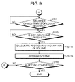
- FIG. 9 is a flowchart of the slice-area setting process performed by the computer shown in FIG. 6 (part 2 ).
- FIGS. 1 to 5 A concept of a method of setting a slice area by a magnetic resonance imaging (MRI) apparatus according to an embodiment of the present invention is explained with reference to FIGS. 1 to 5 . It is assumed that an object to be scanned is an object P, and a sagittal image and a coronal image of the object P have been already taken and stored in the MRI apparatus.
- MRI magnetic resonance imaging
- each of the images includes an image of blood vessel B inside the lower limb.
- the MRI apparatus defines a predetermined number of points on a space reflected on each of the sagittal image and the coronal image, and displays the defined points onto each of the images as shown in FIG. 2 .
- the points are hereinafter referred to as observation points.
- FIG. 2 depicts a case where three observation points are defined, and observation points A 1 , A 2 , and A 3 displayed on the sagittal image indicate the same points as observation points A 1 , A 2 , and A 3 displayed on the coronal image.
- the MRI apparatus displays a connecting line W that connects between an observation point and an observation point on each of the images as shown in FIG. 2 .
- the connecting line W is hereinafter referred to as a wire frame.
- the observation points displayed on the sagittal image and the coronal image are to be used for the operator to specify a point to be included in a slice area.
- an input device such as a mouse or a trackball provided on the console
- the operator rearranges the observation points along the image of the blood vessel B included in each of the images.
- the operator can move or delete an observation point, add a new observation point between two observation points, or add a new observation point that branches out from one of the observation points as a branch point, on each of the images.
- the MRI apparatus changes display of the observation points in response to each of the above operations, and when moving an observation point displayed on the sagittal image, the MRI apparatus moves the same observation point displayed on the coronal image at the same time correspondingly to the movement. Likewise, when moving an observation point displayed on the coronal image, the MRI apparatus moves the same observation point displayed on the sagittal image.
- the MRI apparatus automatically changes display of the wire frame W in conjunction with the change in the observation points as shown in FIG. 3 .
- the operator specifies scanning conditions for actual scanning to the MRI apparatus. Specifically, the operator specifies the number of movements of a couch, and a size of a volume representing a slice area. To specify the size of a volume, the operator specifies lengths of orthogonal three sides of a rectangular parallelepiped that represents the volume. The lengths of the three sides are referred to as a slice length, a slice width, and a slice thickness. After all of the scanning conditions are specified, the operator instructs the MRI apparatus to set a slice area.
- the MRI apparatus When receiving the instruction, the MRI apparatus arranges the volume representing the slice area onto each of the images based on the observation points arranged on the sagittal image and the coronal image, and the specified scanning conditions.
- FIG. 4 is an arrangement of volumes V when the number of movements of the couch is three. As shown in FIG. 4 , the MRI apparatus arranges the volumes V in the specified size by laying out as many as the specified number of movements of the couch along the direction of a body axis of the object P.
- each of the volumes V is arranged such that the most observation points are included inside the volumes V. If observation points are scattered to a great extent, there is a case where all of the observation points may not fall within the volumes in the size specified by the operator.
- the operator checks whether the slice areas are appropriately set by checking a state of the volumes displayed on the sagittal image and the coronal image. If the slice areas are not appropriately set, the operator changes the arrangement of the observation points, or changes the scanning conditions.
- the MRI apparatus dynamically changes the arrangement of the volumes. For example, if the operator changes the number of movements of the couch in the example shown in FIG. 4 to four times, the MRI apparatus increases one volume, and rearranges each of the volumes in accordance with the observation points as shown in FIG. 5 .
- the operator repeats the above operations until the volumes are appropriately arranged, and then instructs the MRI apparatus to perform actual scanning.
- the MRI apparatus sets slice areas based on the arrangement of the volumes on the positioning images at the moment, and performs actual scanning.
- the MRI apparatus when performing scanning a plurality of number times by moving the couch, the MRI apparatus can easily set a slice area for each scanning.
- the MRI apparatus includes a static magnetic-field magnet 1 , a gradient magnetic-field coil 2 , a radiofrequency (RF) coil 3 , a static magnetic-field power supply 4 , a gradient magnetic-field power supply 5 , a transmitter 6 , a receiver 7 , a sequence controller 8 , and a computer 10 .
- RF radiofrequency
- the static magnetic-field magnet 1 is a magnet formed in a cylindrical shape, and generates a static magnetic field H 0 in a space inside a cylinder in which the object P is placed using a current supplied from the static magnetic-field power supply 4 .
- the gradient magnetic-field coil 2 is three pairs of coils arranged inside the static magnetic-field magnet 1 , and generates a gradient magnetic field inside the static magnetic-field magnet 1 along three directions of the x, y, and z-axes using a current supplied from the gradient magnetic-field power supply 5 .
- the RF coil 3 is arranged to be opposed to the object P inside the opening of the static magnetic-field magnet 1 , irradiates the object P with an RF wave sent from the transmitter 6 , and receives a magnetic resonance (MR) signal emitted from hydrogen nuclei in the object P owing to excitation.
- the static magnetic-field power supply 4 supplies a current to the static magnetic-field magnet 1
- the gradient magnetic-field power supply 5 supplies a current to the gradient magnetic-field coil 2 based on an instruction from the sequence controller 8 .
- the transmitter 6 sends an RF wave to the RF coil 3 based on an instruction from the sequence controller 8 , and the receiver 7 detects the MR signal received by the RF coil 3 , and creates raw data by digitalizing the MR signal. After creating the raw data from the MR signal, the receiver 7 sends the created raw data to the sequence controller 8 .
- the sequence controller 8 performs scanning of the object P by activating the gradient magnetic-field power supply 5 , the transmitter 6 , and the receiver 7 , based on sequence information sent from the computer 10 .
- the sequence information defines a procedure when scanning, such as the strength of power to be supplied to the gradient magnetic-field coil 2 by the gradient magnetic-field power supply 5 and the timing of supplying the power, the strength of an RF wave to be sent to the RF coil 3 by the transmitter 6 and the timing of sending the RF wave, and the timing of detecting the MR signal by the receiver 7 .
- the sequence controller 8 transfers the raw data to the computer 10 .
- a configuration of a software program to be executed by the computer 10 shown in FIG. 6 is explained below with reference to FIG. 7 .
- the software program controls the MRI apparatus based on an instruction from the operator, and reconstructs an image from raw data sent from the sequence controller 8 .
- the software program includes an input unit 11 , a display unit 12 , a sequence-controller interface unit 13 , a storage unit 14 , an image reconstructing unit 15 , a control unit 16 , and a slice-area setting unit 17 .
- the input unit 11 is a tool to input various pieces of information, and can be implemented by a pointing device, such as a mouse or a trackball, and a keyboard.
- the input unit 11 receives an instruction about scanning and scanning conditions from the operator, by cooperating with the display unit 12 .
- the input unit 11 receives from the operator instructions, such as an instruction to display a scan image, an instruction to display observation points shown in FIG. 2 , an instruction to change an observation point, an instruction to set a slice area, an instruction to change scanning conditions, and an instruction to execute scanning.
- the input unit 11 at the same time, allows the operator to specify the number of movements of the couch, and the size of a volume representing the slice area, which includes the slice length, the slice width, and the slice thickness, as the scanning conditions.
- the display unit 12 displays various pieces of information, and can be implemented by a cathode ray tube (CRT) display, a liquid crystal display (LCD), or the like.
- CTR cathode ray tube
- LCD liquid crystal display
- the display unit 12 displays an image reconstructed by the image reconstructing unit 15 , and a graphical user interface (GUI) for receiving an instruction about scanning and scanning conditions from the operator.
- GUI graphical user interface
- the sequence-controller interface unit 13 controls sending and receiving of information to be exchanged between the computer 10 and the sequence controller 8 .
- the sequence-controller interface unit 13 sends sequence information for controlling activation of the gradient magnetic-field power supply 5 , the transmitter 6 , and the receiver 7 to the sequence controller 8 , and receives raw data digitalized from a MR signal from the sequence controller B.
- the storage unit 14 stores therein data and a computer program required for various processing performed by the computer 10 , for example, raw data sent from the sequence controller 8 , and an image reconstructed by the image reconstructing unit 15 .
- the image reconstructing unit 15 reconstructs an image from raw data sent from the sequence controller 8 . Specifically, the image reconstructing unit 15 reads raw data stored in the storage unit 14 based on an instruction from the control unit 16 , and reconstructs a three-dimensional image, such as a sagittal image, a coronal image, and an axial image, by performing a predetermined image reconstruction, such as Fourier transform, on the read raw data. After reconstructing the three-dimensional image, the image reconstructing unit 15 stores the reconstructed image into the storage unit 14 .
- a three-dimensional image such as a sagittal image, a coronal image, and an axial image
- a predetermined image reconstruction such as Fourier transform
- the control unit 16 performs various processing for controlling scanning by the MRI apparatus based on an instruction from the operator. From among the various processing performed by the control unit 16 , only processing particularly relevant to the present invention is explained below.
- the control unit 16 fetches the instructed image from images stored in the storage unit 14 , and displays the fetched image on the display unit 12 .
- the control unit 16 connects divided images, and then displays the connected images on the display unit 12 .
- the control unit 16 When receiving via the input unit 11 an instruction to display observation points, an instruction to change an observation point, an instruction to set a slice area, or an instruction to change scanning conditions, the control unit 16 instructs the slice-area setting unit 17 to perform display of observation points, change of an observation point, setting of a slice area, or change in scanning conditions, based on each of the instructions.
- the control unit 16 When setting information for setting a slice area is sent from the slice-area setting unit 17 as a result of the instruction to set a slice area, the control unit 16 stores the setting information into an internal memory.
- the setting information includes information required for creating sequence information, for example, information indicating the size, the position, and the orientation/inclination of a slice area/slice volume.
- control unit 16 When receiving an instruction to perform scanning via the input unit 11 , the control unit 16 creates sequence information based on setting information stored in the internal memory at the moment, and sends the created sequence information to the sequence controller 8 via the sequence-controller interface unit 13 .
- the sequence controller 8 performs scanning of the object P.
- raw data is transferred from the sequence controller 8 , and then the control unit 16 causes the storage unit 14 to store therein the transferred raw data.
- the control unit 16 then instructs the image reconstructing unit 15 to reconstruct an image from the raw data stored in the storage unit 14 .
- the slice-area setting unit 17 sets a slice area for actual scanning by using positioning images.
- the positioning images to be used for the setting of a slice area are displayed on the display unit 12 by the control unit 16 prior to the setting of the slice area based on an instruction from the operator.
- As the positioning image an image created by connecting images taken separately multiple times by moving the couch can be used.
- the slice-area setting unit 17 displays a certain number of observation points at certain positions on a sagittal image and a coronal image displayed on the display unit 12 as the positioning images.
- control unit 16 displays each of the observation points at a position centered in each of the images before connected.
- the slice-area setting unit 17 displays a wire frame that connects the displayed observation points (see FIG. 2 ).
- the slice-area setting unit 17 when instructed by the control unit 16 to change an observation point, the slice-area setting unit 17 changes the observation point on the sagittal image and the coronal image displayed on the display unit 12 in accordance with an operation by the operator following to the instruction.
- the slice-area setting unit 17 moves the observation point on the sagittal image and the coronal image in response to the operation.
- the slice-area setting unit 17 adds the new observation point onto each of the images in response to the operation.
- the slice-area setting unit 17 deletes the observation point from each of the images in response to the operation.
- the slice-area setting unit 17 adds the new observation point onto each of the images in response to the operation.
- the slice-area setting unit 17 changes display of the observation points in accordance with each of the above operations, and when an observation point displayed on the sagittal image is changed, the slice-area setting unit 17 correspondingly changes the same observation point displayed on the coronal image at the same time. Likewise, when an observation point displayed on the coronal image is changed, the slice-area setting unit 17 changes the same observation point displayed on the sagittal image correspondingly to the change.
- the operator can adjust the arrangement of the observation points while visually checking from two directions, and can arrange the observation points easily and accurately.
- the slice-area setting unit 17 changes the arrangement of the wire frame in accordance with the changed observation points (see FIG. 3 ).
- the slice-area setting unit 17 dynamically changes display of the wire frame based on the changed arrangement of the observation points, so that if the operator arranges the observation points on a blood vessel, the wire frame is displayed along the blood vessel. Accordingly, the operator can visually check displacement of the observation points from the blood vessel easily, so that the operator can arrange the observation points accurately on the blood vessel.
- the slice-area setting unit 17 when the slice-area setting unit 17 is instructed by the control unit 16 to set a slice area, the slice-area setting unit 17 arranges a volume representing the slice area based on scanning conditions (the number of movements of the couch, and a slice length, a slice width, and a slice thickness that indicate the size of the volume of the slice area) specified at the same time to the instruction, and observation points arranged on the positioning images at the moment.
- scanning conditions the number of movements of the couch, and a slice length, a slice width, and a slice thickness that indicate the size of the volume of the slice area
- the slice-area setting unit 17 divides a space reflected on each of the positioning images, namely the sagittal image and the coronal image, into spaces as many as the specified number of movements of the couch at regular intervals in a moving direction of the couch, and defines an approximate plane that resembles the distribution of the observation points with respect to each of the divided spaces based on observation points included in each of the spaces, for example, by using least square approximation.
- the slice area setting unit 17 defines a volume (rectangular parallelepiped) having the specified slice length, the specified slice width, and the specified slice thickness as three sides orthogonal to each other, and calculates the position and the orientation/inclination of the volume such that the most observation points are included inside the volume, and the volume is positioned in parallel with the approximate plane.
- the slice area setting unit 17 then arranges the volume into each of the divided spaces based on the calculated position and the calculated orientation/inclination.
- the volumes are arranged to overlap each other at the border of each space (see FIG. 4 ).
- the slice area setting unit 17 changes the arrangement of the observation points and the wire frame on the sagittal image and the coronal image in response to each of the instructions. Furthermore, the slice area setting unit 17 recalculates the position and the orientation/inclination of the volume based on the changed arrangement of the observation points, and rearranges the volumes based on the recalculated position and the recalculated inclination (see FIG. 5 ).
- the operator can change an arrangement of observation points while checking the state of volumes, so that the operator can set a slice area efficiently.
- the operator can change the number of movements of the couch and the size of the volume while checking the state of the volumes, so that the operator can set a slice area efficiently.
- the slice area setting unit 17 sends setting information including the size, the position, and the orientation/inclination of the volume to the control unit 16 each time of rearrangement.
- the processing can be performed as follows. For example, when volumes are arranged, the slice-area setting unit 17 calculates the shortest distance from each of observation points included in a volume to a slice plane (a plane of a rectangular parallelepiped having the slice length and the slice width as two sides), and specifies the closest observation point to the slice plane. If the distance from the specified observation point to the slice plane exceeds a threshold, the slice-area setting unit 17 reduces the slice thickness of the volume to an extent at which the distance satisfies the threshold.
- a slice plane a plane of a rectangular parallelepiped having the slice length and the slice width as two sides
- the time required for scanning can be reduced to the minimum time by setting the size of the volume to make the slice thickness as thin as possible in this way.
- the slice-area setting unit 17 can be configured to notify the operator that some of the observation points are not included in the slice area by changing a color of display or flashing of display of an observation point not included in the volume. The notification can suggest rethinking the size of the volume and the scanning conditions to the operator.
- a flow of setting a slice area performed by the computer 10 is explained below with reference to FIGS. 8 and 9 .
- the control unit 16 displays the specified sagittal image and the specified coronal image of the object P on the display unit 12 (Step S 101 ).
- the slice-area setting unit 17 displays the observation points onto the sagittal image and the coronal image displayed on the display unit 12 (Step S 102 ), and further displays the wire frame that connects the displayed observation points (Step S 103 ).
- the slice-area setting unit 17 moves the observation point on the sagittal image and the coronal image in response to the instruction (Step S 105 ).
- the slice-area setting unit 17 adds a new observation point between two observation points displayed on the sagittal image and the coronal image in response to the instruction (Step S 107 ).
- the slice-area setting unit 17 deletes the observation point displayed on the sagittal image and the coronal image in response to the instruction (Step S 109 ).
- the slice-area setting unit 17 adds a new observation point to branch off from one of the observation points displayed on the sagittal image and the coronal image based on the instruction (Step S 111 ).
- the slice-area setting unit 17 calculates the position and the inclination of the volume based on the observation points and the scanning conditions (Step S 114 ), and arranges the volume on the sagittal image and the coronal image displayed on the display unit 12 based on the calculated position and the calculated inclination (Step S 115 ).
- the computer 10 repeats the processing of steps S 104 to S 115 until the operator completes the operation for setting the slice area.
- the computer 10 terminates the processing (Yes at Step S 116 ).
- the operator can change an arrangement of observation points while checking the state of volumes, so that the operator can set a slice area efficiently.
- a slice area for each scanning can be easily set.
- the MRI apparatus receives an operation about an arrangement of observation points and scanning conditions from an operator, and sets a slice area with respect to each movement of the couch based on the observation points and the scanning conditions
- the method of setting a slice area is not limited to this.
- the MRI apparatus can be configured to acquire characteristic information representing anatomical characteristics of an object from a positioning image taken in advance, and to set a slice area based on the acquired characteristic information.
- the slice-area setting unit 17 extracts the length of a scan region along the direction of moving the couch from the positioning image of the object, and calculates the number of movements of the couch from the extracted length.
- the slice-area setting unit 17 then extracts the contour of the scan region from the positioning image, and calculates from the extracted contour the size and the direction of the slice area with respect to each of positions to which the couch is to be moved (hereinafter, “couch positions”) such that the scan region is included in the slice area at each of the couch positions.
- the slice-area setting unit 17 sets a slice area with respect to each of the couch positions in accordance with the calculated number of movements and the calculated size and direction of the slice area as scanning conditions.
- the slice-area setting unit 17 when scanning bone, extracts the contour of the bone from the positioning image, and detects a length, a thickness, and a direction of the bone, from the extracted contour. Based on the detected length, the detected thickness, and the detected direction, the slice-area setting unit 17 then set a slice area with respect to each of the couch positions such that the slice area has a size and a direction to include the whole bone at each of the positions of the couch.
- the MRI apparatus can automatically set a slice area based on the positioning image of the object, so that the operator can set a slice area more easily.
- the slice-area setting unit 17 can be configured to receive information about the number of movements of the couch and the size of the slice area from the operator, and to set the slice area by determining scanning conditions based on the received information.
- the slice-area setting unit 17 can be configured to arrange observation points indicating portions to be included in the slice area onto the positioning image based on characteristic information acquired from the positioning image, and to set a slice area that includes the observation points with respect to each of the couch positions based on the arranged observation points and scanning conditions.
- the slice-area setting unit 17 sets observation points in accordance with a shape and a size of a scan region based on the characteristic information representing anatomical characteristics acquired from the positioning image.
- the slice-area setting unit 17 when scanning the inside of a femur, extracts the contour of the femur from the positioning image, and detects a length, a thickness, and a direction of the femur from the extracted contour. The slice-area setting unit 17 then divides the object region of the femur to be scanned into a certain number of regions determined based on the detected length, and arranges an observation point at a position centered in each of the regions. The slice-area setting unit 17 then sets a slice area with respect to each of the couch positions such that the slice area includes the observation point at each of the positions of the couch.
- slice areas can be set separately with respect to each of the body parts in accordance with branches of the wire frame. For example, when right and left lower limbs are displayed on the positioning image, volumes V are arranged with respect to each of the right and left lower limbs.
- the present invention is not limited to this, but can also be applied to a case where other images taken from different angles, including an axial image, are used as positioning images.
- the slice-area setting unit 17 when the slice-area setting unit 17 arranges observation points on each of positioning images taken from different angles, and changes an arrangement of the observation points arranged on one of the positioning images, the slice-area setting unit 17 changes an arrangement of the observation points arranged on the other positioning image(s) in conjunction with the former change. Accordingly, the operator can adjust the arrangement of the observation points while visually checking from a plurality of directions, and can arrange the observation points easily and accurately.
- an image created by connecting images taken separately multiple times by moving the couch can be used as a positioning image, and the number of movements of the couch during the scanning for the positioning image does not need to match the number of movements of the couch specified as a scanning condition of actual scanning. Accordingly, the MRI apparatus can perform scanning efficiently, for example, by scanning for the positioning image as few times of movements as possible at least to obtain an image quality good enough to arrange observation points, while scanning at the actual scanning an increased number of movements to obtain a high quality image.
- connecting portions do not need to be overlapped. Accordingly, when performing scanning for a positioning image separately multiple times, the number of movements of the couch can be reduced by scanning only portions required to arrange observation points, so that time to be taken to perform scanning for the positioning image can be shortened. Consequently, the total time to be taken for scanning can be decreased, so that a stress on a patient who is the object can be reduced.
Abstract
Description
Claims (25)
Applications Claiming Priority (4)
| Application Number | Priority Date | Filing Date | Title |
|---|---|---|---|
| JP2007017729 | 2007-01-29 | ||
| JP2007-017729 | 2007-01-29 | ||
| JP2007-280655 | 2007-10-29 | ||
| JP2007280655A JP5209271B2 (en) | 2007-01-29 | 2007-10-29 | Magnetic resonance imaging apparatus and slice region setting method |
Publications (2)
| Publication Number | Publication Date |
|---|---|
| US20080180104A1 US20080180104A1 (en) | 2008-07-31 |
| US7659720B2 true US7659720B2 (en) | 2010-02-09 |
Family
ID=39667228
Family Applications (1)
| Application Number | Title | Priority Date | Filing Date |
|---|---|---|---|
| US12/020,335 Active 2028-03-30 US7659720B2 (en) | 2007-01-29 | 2008-01-25 | Magnetic resonance imaging apparatus and method of setting slice-area/slice-volume orientation at each moved couch position |
Country Status (1)
| Country | Link |
|---|---|
| US (1) | US7659720B2 (en) |
Cited By (9)
| Publication number | Priority date | Publication date | Assignee | Title |
|---|---|---|---|---|
| US20090309595A1 (en) * | 2005-06-09 | 2009-12-17 | Yumiko Yatsui | Magnetic resonance imaging method and apparatus |
| US20090315561A1 (en) * | 2008-06-24 | 2009-12-24 | Stefan Assmann | Magnetic resonance data acquisition system and method with parameter adjustment during patient movement |
| US20100194390A1 (en) * | 2009-02-04 | 2010-08-05 | Stephan Kannengiesser | Magnetic resonance method and apparatus for time-resolved acquisition of magnetic resonance data |
| US20100201360A1 (en) * | 2009-02-10 | 2010-08-12 | Kabushiki Kaisha Toshiba | Magnetic resonance imaging apparatus |
| US20100286802A1 (en) * | 2009-05-11 | 2010-11-11 | Thorsten Feiweier | Method to operate an imaging system, and imaging system |
| US20100290688A1 (en) * | 2009-05-18 | 2010-11-18 | Takao Goto | Slice determination apparatus, magnetic resonance imaging system, and slice setting method |
| US20110012594A1 (en) * | 2008-11-21 | 2011-01-20 | Olympus Medical Systems Corp. | Position detecting system and position detecting method |
| US20110101980A1 (en) * | 2009-10-29 | 2011-05-05 | Yoshiharu Ohiwa | Magnetic resonance imaging apparatus |
| US20130265045A1 (en) * | 2012-04-06 | 2013-10-10 | Dan Xu | System and method for multistation image pasting for whole body diffusion-weighted imaging |
Families Citing this family (6)
| Publication number | Priority date | Publication date | Assignee | Title |
|---|---|---|---|---|
| JP5053594B2 (en) * | 2006-08-11 | 2012-10-17 | 株式会社東芝 | Magnetic resonance diagnostic equipment |
| US7659720B2 (en) * | 2007-01-29 | 2010-02-09 | Toshiba Kk | Magnetic resonance imaging apparatus and method of setting slice-area/slice-volume orientation at each moved couch position |
| DE102014219782A1 (en) * | 2014-09-30 | 2016-03-31 | Siemens Aktiengesellschaft | Operation of an imaging medical examination device with a plurality of subsystems |
| DE102014219779B4 (en) * | 2014-09-30 | 2016-06-02 | Siemens Aktiengesellschaft | Operation of an imaging medical examination device with a plurality of subsystems |
| EP3413073A1 (en) * | 2017-06-07 | 2018-12-12 | Siemens Healthcare GmbH | Contrast-enhanced mr angiography with estimation of the flow velocity of the contrast agent |
| CN109171744A (en) * | 2018-08-28 | 2019-01-11 | 北京中科启上科技有限公司 | Collecting method and device for lower limb |
Citations (13)
| Publication number | Priority date | Publication date | Assignee | Title |
|---|---|---|---|---|
| JPH06189934A (en) | 1992-09-16 | 1994-07-12 | Toshiba Medical Eng Co Ltd | Slice position designation method for mri device |
| US20020021128A1 (en) * | 2000-04-25 | 2002-02-21 | Shigehide Kuhara | Magnetic resonance imaging involving movement of patient's couch |
| US20020140423A1 (en) * | 2001-03-30 | 2002-10-03 | Brittain Jean Helen | Moving table MRI with frequency-encoding in the z-direction |
| US20020173715A1 (en) * | 2001-04-09 | 2002-11-21 | Kruger David G. | Method for acquiring MRI data from a large field of view using continuous table motion |
| US20030011369A1 (en) * | 2001-03-30 | 2003-01-16 | Brittain Jean H. | Moving table MRI with frequency-encoding in the z-direction |
| US6512373B1 (en) * | 1999-03-25 | 2003-01-28 | Siemens Aktiengesellschaft | Magnetic resonance tomography device having an operator control and monitoring device with a spatially modifiable apparatus for defining an orientation of a tomographic image |
| JP2003290172A (en) | 2002-04-03 | 2003-10-14 | Toshiba Medical System Co Ltd | Mri unit |
| JP2003290171A (en) | 2002-04-02 | 2003-10-14 | Toshiba Medical System Co Ltd | Mri unit |
| US6801034B2 (en) * | 2001-03-30 | 2004-10-05 | General Electric Company | Method and apparatus of acquiring large FOV images without slab-boundary artifacts |
| US20040263171A1 (en) * | 1998-09-30 | 2004-12-30 | Kabushiki Kaisha Toshiba | Magnetic resonance imaging arraratus |
| JP2006129937A (en) | 2004-11-02 | 2006-05-25 | Hitachi Medical Corp | Magnetic resonance imaging apparatus |
| US20080039867A1 (en) * | 2003-11-12 | 2008-02-14 | Micro-Epsilon Messtechnik Gmbh & Co. Kg | Actuator Platform For Guiding End Effectors In Minimally Invasive Interventions |
| US20080180104A1 (en) * | 2007-01-29 | 2008-07-31 | Naoyuki Furudate | Magnetic resonance imaging apparatus and method of setting slice area |
-
2008
- 2008-01-25 US US12/020,335 patent/US7659720B2/en active Active
Patent Citations (18)
| Publication number | Priority date | Publication date | Assignee | Title |
|---|---|---|---|---|
| JPH06189934A (en) | 1992-09-16 | 1994-07-12 | Toshiba Medical Eng Co Ltd | Slice position designation method for mri device |
| US20040263171A1 (en) * | 1998-09-30 | 2004-12-30 | Kabushiki Kaisha Toshiba | Magnetic resonance imaging arraratus |
| US6512373B1 (en) * | 1999-03-25 | 2003-01-28 | Siemens Aktiengesellschaft | Magnetic resonance tomography device having an operator control and monitoring device with a spatially modifiable apparatus for defining an orientation of a tomographic image |
| US20020021128A1 (en) * | 2000-04-25 | 2002-02-21 | Shigehide Kuhara | Magnetic resonance imaging involving movement of patient's couch |
| US6946836B2 (en) * | 2000-04-25 | 2005-09-20 | Kabushiki Kaisha Toshiba | Magnetic resonance imaging involving movement of patient's couch |
| US20040155654A1 (en) * | 2001-03-30 | 2004-08-12 | Brittain Jean Helen | Moving table MRI with frequency-encoding in the z-direction |
| US20030011369A1 (en) * | 2001-03-30 | 2003-01-16 | Brittain Jean H. | Moving table MRI with frequency-encoding in the z-direction |
| US6794869B2 (en) * | 2001-03-30 | 2004-09-21 | General Electric Company | Moving table MRI with frequency-encoding in the z-direction |
| US6801034B2 (en) * | 2001-03-30 | 2004-10-05 | General Electric Company | Method and apparatus of acquiring large FOV images without slab-boundary artifacts |
| US6891374B2 (en) * | 2001-03-30 | 2005-05-10 | General Electric Company | Moving table MRI with frequency-encoding in the z-direction |
| US6897655B2 (en) * | 2001-03-30 | 2005-05-24 | General Electric Company | Moving table MRI with frequency-encoding in the z-direction |
| US20020140423A1 (en) * | 2001-03-30 | 2002-10-03 | Brittain Jean Helen | Moving table MRI with frequency-encoding in the z-direction |
| US20020173715A1 (en) * | 2001-04-09 | 2002-11-21 | Kruger David G. | Method for acquiring MRI data from a large field of view using continuous table motion |
| JP2003290171A (en) | 2002-04-02 | 2003-10-14 | Toshiba Medical System Co Ltd | Mri unit |
| JP2003290172A (en) | 2002-04-03 | 2003-10-14 | Toshiba Medical System Co Ltd | Mri unit |
| US20080039867A1 (en) * | 2003-11-12 | 2008-02-14 | Micro-Epsilon Messtechnik Gmbh & Co. Kg | Actuator Platform For Guiding End Effectors In Minimally Invasive Interventions |
| JP2006129937A (en) | 2004-11-02 | 2006-05-25 | Hitachi Medical Corp | Magnetic resonance imaging apparatus |
| US20080180104A1 (en) * | 2007-01-29 | 2008-07-31 | Naoyuki Furudate | Magnetic resonance imaging apparatus and method of setting slice area |
Cited By (16)
| Publication number | Priority date | Publication date | Assignee | Title |
|---|---|---|---|---|
| US20090309595A1 (en) * | 2005-06-09 | 2009-12-17 | Yumiko Yatsui | Magnetic resonance imaging method and apparatus |
| US7821267B2 (en) * | 2005-06-09 | 2010-10-26 | Hitachi Medical Corporation | Magnetic resonance imaging method and apparatus |
| US20090315561A1 (en) * | 2008-06-24 | 2009-12-24 | Stefan Assmann | Magnetic resonance data acquisition system and method with parameter adjustment during patient movement |
| US8502532B2 (en) * | 2008-06-24 | 2013-08-06 | Siemens Aktiengesellschaft | Magnetic resonance data acquisition system and method with recursively adapted object-specific measurement parameter adjustment during patient movement through the MRI system |
| US20110012594A1 (en) * | 2008-11-21 | 2011-01-20 | Olympus Medical Systems Corp. | Position detecting system and position detecting method |
| US8049503B2 (en) * | 2008-11-21 | 2011-11-01 | Olympus Medical Systems Corp. | Position detecting system and position detecting method |
| US8598873B2 (en) * | 2009-02-04 | 2013-12-03 | Siemens Aktiengesellschaft | Magnetic resonance method and apparatus for time-resolved acquisition of magnetic resonance data |
| US20100194390A1 (en) * | 2009-02-04 | 2010-08-05 | Stephan Kannengiesser | Magnetic resonance method and apparatus for time-resolved acquisition of magnetic resonance data |
| US20100201360A1 (en) * | 2009-02-10 | 2010-08-12 | Kabushiki Kaisha Toshiba | Magnetic resonance imaging apparatus |
| US8664953B2 (en) * | 2009-02-10 | 2014-03-04 | Kabushiki Kaisha Toshiba | Magnetic resonance imaging apparatus setting field-of-view (FOV) based on patient size and region of interest (ROI) |
| US20100286802A1 (en) * | 2009-05-11 | 2010-11-11 | Thorsten Feiweier | Method to operate an imaging system, and imaging system |
| US8633690B2 (en) * | 2009-05-11 | 2014-01-21 | Siemens Aktiengesellschaft | Method of operating an MRI imaging system, while also controlling graadient and shim sub-systems along with the MRI imaging system |
| US20100290688A1 (en) * | 2009-05-18 | 2010-11-18 | Takao Goto | Slice determination apparatus, magnetic resonance imaging system, and slice setting method |
| US20110101980A1 (en) * | 2009-10-29 | 2011-05-05 | Yoshiharu Ohiwa | Magnetic resonance imaging apparatus |
| US9157977B2 (en) * | 2009-10-29 | 2015-10-13 | Kabushiki Kaisha Toshiba | Magnetic resonance imaging apparatus with optimal excitation angle |
| US20130265045A1 (en) * | 2012-04-06 | 2013-10-10 | Dan Xu | System and method for multistation image pasting for whole body diffusion-weighted imaging |
Also Published As
| Publication number | Publication date |
|---|---|
| US20080180104A1 (en) | 2008-07-31 |
Similar Documents
| Publication | Publication Date | Title |
|---|---|---|
| US7659720B2 (en) | Magnetic resonance imaging apparatus and method of setting slice-area/slice-volume orientation at each moved couch position | |
| JP4129375B2 (en) | Medical image diagnostic apparatus and image region designation support method | |
| JP4070457B2 (en) | Apparatus and method for acquiring partial images as needed | |
| US9250306B2 (en) | Magnetic resonance imaging using technique of positioning multi-slabs to be imaged | |
| JP7246864B2 (en) | Image processing device, magnetic resonance imaging device and image processing program | |
| US8831703B2 (en) | Selective MR imaging of segmented anatomy | |
| JP6427488B2 (en) | Magnetic resonance system and magnetic resonance method | |
| US20190015010A1 (en) | Magnetic resonance imaging apparatus and imaging planning method | |
| US7514929B2 (en) | Magnetic resonance imaging apparatus and static magnetic field correction method | |
| US8855382B2 (en) | MRI mammography with facilitated comparison to other mammography images | |
| CN110755075A (en) | Magnetic resonance imaging method, apparatus, device and storage medium | |
| US20140132268A1 (en) | Magnetic resonance imaging apparatus and imaging position setting assissting method | |
| US10976397B2 (en) | MRI apparatus utilizing non-ultrashort TE(UTE) imaging to generate a mask image for performance of mask processing | |
| JP5209271B2 (en) | Magnetic resonance imaging apparatus and slice region setting method | |
| US20020151785A1 (en) | Mehtod and magnetic resonance tomography apparatus for preparing a data acquisition using previously obtained data acquisitions | |
| US20150077114A1 (en) | Magnetic resonance imaging apparatus | |
| US11650281B2 (en) | Excitation region setting method and magnetic resonance imaging apparatus | |
| US20130141097A1 (en) | Magnetic resonance imaging apparatus | |
| JP2018007817A (en) | Magnetic resonance imaging apparatus and control method of the same | |
| US20240027555A1 (en) | Magnetic resonance imaging apparatus | |
| JP7399785B2 (en) | Magnetic resonance imaging equipment and programs | |
| JP2014132958A (en) | Magnetic resonance imaging apparatus and imaging processing method | |
| JP4429867B2 (en) | Magnetic resonance imaging system | |
| US20200271742A1 (en) | Magnetic resonance imaging apparatus and control program for magnetic resonance imaging apparatus | |
| JP6351933B2 (en) | Magnetic resonance imaging system |
Legal Events
| Date | Code | Title | Description |
|---|---|---|---|
| AS | Assignment |
Owner name: KABUSHIKI KAISHA TOSHIBA, JAPAN Free format text: ASSIGNMENT OF ASSIGNORS INTEREST;ASSIGNOR:FURUDATE, NAOYUKI;REEL/FRAME:020421/0127 Effective date: 20080109 Owner name: TOSHIBA MEDICAL SYSTEMS CORPORATION, JAPAN Free format text: ASSIGNMENT OF ASSIGNORS INTEREST;ASSIGNOR:FURUDATE, NAOYUKI;REEL/FRAME:020421/0127 Effective date: 20080109 Owner name: KABUSHIKI KAISHA TOSHIBA,JAPAN Free format text: ASSIGNMENT OF ASSIGNORS INTEREST;ASSIGNOR:FURUDATE, NAOYUKI;REEL/FRAME:020421/0127 Effective date: 20080109 Owner name: TOSHIBA MEDICAL SYSTEMS CORPORATION,JAPAN Free format text: ASSIGNMENT OF ASSIGNORS INTEREST;ASSIGNOR:FURUDATE, NAOYUKI;REEL/FRAME:020421/0127 Effective date: 20080109 |
|
| STCF | Information on status: patent grant |
Free format text: PATENTED CASE |
|
| CC | Certificate of correction | ||
| FEPP | Fee payment procedure |
Free format text: PAYOR NUMBER ASSIGNED (ORIGINAL EVENT CODE: ASPN); ENTITY STATUS OF PATENT OWNER: LARGE ENTITY |
|
| FPAY | Fee payment |
Year of fee payment: 4 |
|
| AS | Assignment |
Owner name: TOSHIBA MEDICAL SYSTEMS CORPORATION, JAPAN Free format text: ASSIGNMENT OF ASSIGNORS INTEREST;ASSIGNOR:KABUSHIKI KAISHA TOSHIBA;REEL/FRAME:038891/0693 Effective date: 20160316 |
|
| FPAY | Fee payment |
Year of fee payment: 8 |
|
| MAFP | Maintenance fee payment |
Free format text: PAYMENT OF MAINTENANCE FEE, 12TH YEAR, LARGE ENTITY (ORIGINAL EVENT CODE: M1553); ENTITY STATUS OF PATENT OWNER: LARGE ENTITY Year of fee payment: 12 |