US7710693B2 - Apparatus and method for providing protection for a synchronous electrical generator in a power system - Google Patents
Apparatus and method for providing protection for a synchronous electrical generator in a power system Download PDFInfo
- Publication number
- US7710693B2 US7710693B2 US11/534,587 US53458706A US7710693B2 US 7710693 B2 US7710693 B2 US 7710693B2 US 53458706 A US53458706 A US 53458706A US 7710693 B2 US7710693 B2 US 7710693B2
- Authority
- US
- United States
- Prior art keywords
- generator
- curve
- phase
- limit
- active power
- Prior art date
- Legal status (The legal status is an assumption and is not a legal conclusion. Google has not performed a legal analysis and makes no representation as to the accuracy of the status listed.)
- Active, expires
Links
Images


Classifications
-
- H—ELECTRICITY
- H02—GENERATION; CONVERSION OR DISTRIBUTION OF ELECTRIC POWER
- H02H—EMERGENCY PROTECTIVE CIRCUIT ARRANGEMENTS
- H02H7/00—Emergency protective circuit arrangements specially adapted for specific types of electric machines or apparatus or for sectionalised protection of cable or line systems, and effecting automatic switching in the event of an undesired change from normal working conditions
- H02H7/06—Emergency protective circuit arrangements specially adapted for specific types of electric machines or apparatus or for sectionalised protection of cable or line systems, and effecting automatic switching in the event of an undesired change from normal working conditions for dynamo-electric generators; for synchronous capacitors
- H02H7/065—Emergency protective circuit arrangements specially adapted for specific types of electric machines or apparatus or for sectionalised protection of cable or line systems, and effecting automatic switching in the event of an undesired change from normal working conditions for dynamo-electric generators; for synchronous capacitors against excitation faults
-
- H—ELECTRICITY
- H02—GENERATION; CONVERSION OR DISTRIBUTION OF ELECTRIC POWER
- H02P—CONTROL OR REGULATION OF ELECTRIC MOTORS, ELECTRIC GENERATORS OR DYNAMO-ELECTRIC CONVERTERS; CONTROLLING TRANSFORMERS, REACTORS OR CHOKE COILS
- H02P9/00—Arrangements for controlling electric generators for the purpose of obtaining a desired output
- H02P9/006—Means for protecting the generator by using control
Definitions
- the present invention generally relates to synchronous generators, and more specifically, to an apparatus and method for providing generator protection for a synchronous electrical generator in a power system.
- Synchronous electrical generators (“synchronous generators”) are used in many applications requiring alternating current (AC) power generation.
- electric utility systems or power systems include a variety of power system elements such as synchronous generators, power transformers, power transmission lines, distribution lines, buses, capacitors, etc. to generate, transmit and distribute electrical energy to loads.
- a synchronous generator operates to, for example, convert mechanical rotation via a prime mover (e.g., shaft rotation provided by a coal powered steam turbine) into AC current via electromagnetic principles. After suitable conditioning, the alternating electrical current is transmitted and distributed as three-phase electric power to a variety of loads.
- prime mover e.g., shaft rotation provided by a coal powered steam turbine
- synchronous generator design is based on Faraday's law of electromagnetic induction and includes a rotational portion for inducing an electromotive force (EMF) in a stationary portion.
- the rotational portion is driven by the prime mover. More specifically, the rotational portion, or rotor, includes a field winding wrapped around a rotor body, and the stationary portion includes a stator having an armature winding.
- the rotor body typically made of steel, may have a salient pole structure (i.e., poles protruding from a shaft) or a cylindrical structure.
- EMFs are induced in the armature windings of the stator upon application of DC current to the field winding of the rotor. That is, direct current is made to flow in the field winding. This results in a magnetic field, and when the rotor is made to rotate at a constant speed, the magnetic field rotates with it. Accordingly, as the moving magnetic field passes through the stator winding(s), an EMF is induced therein.
- the stationary armature includes, for example, three stationary armature windings, they experience a periodically varying magnetic field, and three EMFs are induced therein. These three EMFs conform a three-phase system of voltages. Thus, for 60-Hz AC systems, in a two-pole machine, the rotor has to rotate at 3600 revolutions per minute with three armature windings displaced equally in space on the stator body to generate three-phase electric power.
- VARs reactive volt-amperes
- VAR or MVAR is the imaginary counterpart of the Watt or Megawatt and represents the reactive power consumed or generated by a reactive load (i.e., a load having a phase difference between the applied voltage and the current).
- Capability curves are typically provided by a generator manufacturer to define the operating or thermal limits of a particular synchronous generator at different cooling pressures.
- Each capability curve represents the synchronous generator capability limit for a pressurized coolant (e.g., hydrogen) circulating to cool the stator and rotor windings. More cooling enables more armature current to flow during synchronous generator operation, while less cooling enables less current to flow.
- over excitation limiter (OEL) curves and minimum excitation limiter (MEL) curves are typically included with the manufacturer-provided capability curves.
- Steady state stability limit (SSSL) curves may further be determined with generator impedance data and power system parameters.
- the operating limits reflected in the capability curves are imposed on the amount of Watts and VARs that the synchronous generator can deliver to the power system. There is also a minimum value of current that must flow in the rotor field to maintain generator stability, and this imposes a limit on the amount of VARs that the synchronous generator can absorb for each delivered active power value.
- the operating limits graphically illustrated by the capability curve(s) include an active power component “P” expressed in Megawatts (MW) and a reactive power component “Q” expressed in Mega VARs (MVARs).
- P active power component
- Q operating point of the synchronous generator i.e., as long as the amount of Watts and VARs flowing out of or into the generator
- the synchronous generator will operate within safe limits.
- protective devices are operatively coupled to the synchronous generators and their outputs in order to measure currents and voltages indicative of synchronous generator operation.
- Such protective devices are referred to hereinafter as protective relays, and typically include a variety of protective functions or elements.
- a method enables protection for a synchronous generator.
- the method includes deriving a plurality of generator safe operating boundary data expressions from a plurality of power system data.
- the power system data may be supplied by a manufacturer of the synchronous generator.
- the power system data may include generator impedance.
- the power system data may include power system parameters such as equivalent power system impedance.
- the generator safe operating boundary data expressions may be used by a protective relay.
- the protective relay utilizes at least one of the plurality of generator safe operating boundary data expressions to enable the protection for the synchronous generator.
- Each of the plurality of generator safe operating boundary data expressions is selected from the group consisting of quadratic equations, circle equations, look-up tables, linear equations and combinations thereof.
- the generator safe operating boundary data expressions may be set in relation to a generator capability curve, a steady-state stability limit curve, a minimum excitation limiter curve, or an over excitation limiter curve. It is contemplated that the user may manually set the generator safe operating boundary data expressions (e.g., in relation to a manufacturer provided generator capability curve, by providing generator safe operating boundaries such as the capability curve and user-defined loss-of-field element) or, in some cases, the generator safe operating boundary data expressions may be derived based on generator and/or power system operating limits (e.g., in relation to a steady-state stability limit curve, a minimum excitation limiter curve, or an over excitation limiter curve). In one embodiment, the protective relay determines the generator safe operating boundary data expressions automatically using generator capability curve data, generator impedance data and power system impedance data.
- the generator safe operating boundary data expression is set for loss-of-field protection.
- a loss-of-field element is provided which is set with respect to the generator capability curve.
- a loss-of-field element is provided which is set with respect to an SSSL curve.
- one or more active power elements, and/or an undervoltage element may further be provided.
- a method provides protection for a synchronous generator.
- the method includes selecting at least one of a plurality of generator safe operating boundary data expressions based on a predetermined user programmable input and a generator operating indication.
- the plurality of generator safe operating boundary data expressions is derived from either an SSSL curve, a plurality of generator safe operating boundaries supplied by a manufacturer of the synchronous generator, or other similar means.
- the method also includes calculating an active power value sum and a reactive power value sum based on measured three-phase currents and voltages associated with synchronous generator operation.
- the method further includes comparing the active power value sum and the reactive power value sum to the at least one of the plurality of generator safe operating boundary data expressions, and providing the protection for the synchronous generator based on this comparison.
- An apparatus provides protection for a synchronous generator in a power system.
- the apparatus comprises a means for deriving a plurality of digitized signals representative of measured three-phase secondary currents and voltages associated with synchronous generator operation, and a microcontroller operatively coupled to the means for deriving the plurality of digitized signals.
- the microcontroller includes a microprocessor and a memory operatively coupled to the microprocessor.
- the microcontroller is programmed to, based on a plurality of predetermined user programmable inputs and generator operating indications, select at least one of a plurality of generator safe operating boundary data expressions.
- the plurality of generator safe operating boundary data expressions may be derived from a plurality of generator safe operating boundaries supplied by a manufacturer of the synchronous generator.
- the plurality of generator safe operating boundary data expressions may be derived from user-defined values such as coordinates of a loss-of-field element.
- the microcontroller is also programmed to calculate an active power value sum and a reactive power value sum based on the plurality of digitized signals, compare the active power value sum and the reactive power value sum to the at least one of the plurality of generator safe operating boundary data expressions, and provide protection for the synchronous generator based on this comparison.
- a computer readable medium having program code recorded thereon provides protection for a synchronous generator in a power system.
- the computer readable medium includes a first program code for selecting at least one of a plurality of generator safe operating boundary data expressions based on a generator operating indication and a predetermined user programmable input.
- the plurality of generator safe operating boundary data expressions is derived from a plurality of generator safe operating boundaries supplied by a manufacturer of the synchronous generator.
- the computer readable medium also includes a second program code for calculating an active power value sum and a reactive power value sum based on measured three-phase currents and voltages associated with synchronous generator operation, a third program code for comparing the active power value sum and reactive power value sum to at least one of the plurality of generator safe operating boundary data expressions, and a fourth program code for providing the protection for the synchronous generator based on the comparison.
- FIG. 1 is a single line schematic of a power system that may be utilized in a typical wide area network.
- FIG. 2 a is an exemplary functional block of a generator protective relay of FIG. 1 , according to an embodiment of the invention.
- FIG. 2 b is an exemplary functional block of the generator operating boundary function of generator protection relay of FIG. 2 a.
- FIG. 2 c is an exemplary functional block of the generator operating boundary function adapted for providing positive-sequence values of generator protection relay of FIG. 2 a.
- FIG. 3 is an exemplary set of generator capability curves that may be provided by a synchronous generator manufacturer to define the operating limits of a synchronous generator of FIG. 1 .
- FIG. 4 is one of the capability curves of the exemplary set of generator capability curves of FIG. 3 .
- FIG. 5 a is a flowchart of a method for synchronous generator protection in the power system of FIG. 1 , according to an embodiment of the invention.
- FIG. 5 b is a flowchart of a method for asserting either an alarm condition or trip condition for synchronous generator protection in the power system of FIG. 1 , according to an embodiment of the invention.
- FIG. 6 is a generator capability curve generated based on generator safe operating boundary data expressions derived from the capability curve of FIG. 4 for use by the generator protection relay of FIG. 2 a , according to an embodiment of the invention.
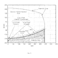
- FIG. 7 is a graphical representation of an estimation curve for the boundary for field winding heating associated with the field winding current limit of a generator capability curve.
- FIG. 8 is a graphical representation of an estimation curve for the boundary for armature heating associated with the armature current limit of a generator capability curve.
- FIG. 9 is a graphical representation of an estimation curve for the boundary for a stator core temperature associated with the stator end region heating limit of a generator capability curve.
- FIG. 10 is a generator capability curve including an arrangement for loss-of-field protection further illustrating the protection zone whereupon a trip signal would be asserted if a condition were to fall therein.
- FIG. 11 is another generator capability curve including an arrangement for loss-of-field protection further illustrating the protection zone whereupon a trip signal would be asserted if a condition were to fall therein.
- FIG. 12 is a generator capability curve including an arrangement for issuing an alarm signal and showing the alarming zone.
- FIG. 13 is a generator capability curve including an arrangement for loss-of-field protection, and an arrangement for issuing an alarm signal, and also showing the generator normal operation zone, the protection zone, and the alarming zone.
- FIG. 1 is a single line schematic diagram of a power system 10 that may be utilized in a typical wide area system.
- the power system 10 includes, among other things, three synchronous generators 11 , 12 and 13 , configured to generate three-phase voltage sinusoidal waveforms such as 12 kV sinusoidal waveforms, three step-up power transformers 14 a , 14 b and 14 c , configured to increase the generated voltage sinusoidal waveforms to higher voltage sinusoidal waveforms such as 138 kV sinusoidal waveforms and a number of circuit breakers 18 .
- the step-up power transformers 14 a , 14 b , 14 c operate to provide the higher voltage sinusoidal waveforms to a number of long distance transmission lines such as the transmission lines 20 a , 20 b and 20 c .
- a first substation 16 may be defined to include the two synchronous generators 11 and 12 , the two step-up power transformers 14 a and 14 b and associated circuit breakers 18 , all interconnected via a first bus 19 .
- a second substation 35 may be defined to include the synchronous generator 13 , the step-up power transformer 14 c and associated circuit breakers 18 , all interconnected via a second bus 25 .
- a third substation 22 includes two step-down power transformers 24 a and 24 b configured to transform the higher voltage sinusoidal waveforms to lower voltage sinusoidal waveforms (e.g., 15 kV) suitable for distribution via one or more distribution lines 26 to loads such as a load 32 .
- the second substation 35 also includes two step-down power transformers 24 c and 24 d on respective distribution lines 28 and 29 to transform the higher voltage sinusoidal waveforms, received via the second bus 25 , to lower voltage sinusoidal waveforms suitable for use by respective loads 30 and 34 .
- one or more protective relays are operatively coupled to the synchronous generators 11 , 12 and 13 to measure currents and voltages indicative of synchronous generator operation. Based on the measured currents and/or voltages, one or more protective elements (e.g., an over-voltage element) of the protective relay may operate to actuate a trip action in the event of an abnormal condition.
- one or more protective elements e.g., an over-voltage element
- protection of the generator 12 is provided by a protective relay 100 . While not separately shown, it should be understood that additional protective relays 100 may be included in the power system 10 .
- FIG. 2 a is an exemplary functional block diagram of the protective relay 100 , according to an embodiment of the invention. It should be understood that functional block diagram of FIG. 2 a is only one example of a protective relay implementation of the instant invention, and that other implementations are possible.
- the protective relay 100 includes a number of inputs 101 - 106 configured to receive secondary current waveforms I A , I B , and I C and secondary voltage waveforms V A , V B , and V C from corresponding voltage and current transformers operatively coupled to each of the A-, B- and C-phases provided by the generator 12 .
- the secondary current waveforms I A , I B , and I C and secondary voltage waveforms V A , V B , and V C may be received via a combination of phase-input current transformers, current transformers, voltage transformers, and non-conventional current and voltage sensors.
- the secondary current waveforms I A , I B , and I C and secondary voltage waveforms V A , V B , and V C are processed to determine whether an alarm and/or trip signal should be issued by the protective relay 100 .
- each of the secondary current and voltage waveforms I A , I B , and I C and V A , V B , and V C is further transformed into corresponding scaled sinusoidal waveforms via current transformers 111 - 113 and voltage transformers 114 - 116 respectively, and resistors (not separately illustrated).
- the scaled sinusoidal waveforms are filtered via (hardware) analog low pass filters 121 - 126 .
- a multiplexer 128 selects each of the filtered scaled sinusoidal waveforms, one at a time, and provides the selected filtered scaled sinusoidal waveforms to an analog-to-digital (A/D) converter 130 .
- the A/D converter 130 samples and digitizes each of the selected filtered scaled sinusoidal waveforms to form corresponding digitized signals 131 - 136 .
- the corresponding digitized signals 131 - 136 are representative of the A-, B- and C-phase secondary current and voltage waveforms I A , I B , and I C and V A , V B , and V C , respectively.
- the corresponding digitized signals 131 - 136 are received by a microcontroller 138 (or digital signal processor (DSP) or personal computer ((PC))) for signal processing, where they are digitally filtered via, for example, Cosine filters to eliminate DC and unwanted frequency components.
- a microcontroller 138 or digital signal processor (DSP) or personal computer ((PC))
- DSP digital signal processor
- PC personal computer
- the digital filtering is provided by digital band pass filters (DBPFs) 141 - 146 where DBPFs 141 and 144 perform digital filtering for digitized signals 131 and 134 to form filtered digital signals 161 and 164 representative of the A-phase secondary current and voltage waveforms I A and V A , where DBPFs 142 and 145 perform digital filtering for digitized signals 132 and 135 to form filtered digital signals 162 and 165 representative of the B-phase secondary current and voltage waveforms I B and V B , and where DBPFs 143 and 146 perform digital filtering for digitized signals 133 and 136 to form filtered digital signals 163 and 166 representative of the C-phase secondary current and voltage waveforms I C and V C .
- the filtered digital signals 161 - 166 are further converted into phasor form to enable subsequent calculations by the microcontroller 138 .
- An indication input 180 is also provided to receive generator operating indications such as, for example, pressure transducer inputs indicative of generator operating parameters.
- generator operating indications include cooling pressure, excitation or field current, stator temperature, gearing temperature, ambient temperature and the like.
- the microcontroller 138 includes a generator operating boundary function 148 , and additional generator protection functions 156 that comprise one or more protective elements.
- the additional generator protection functions 156 performs one or more typical protection functions.
- the additional generator protection functions 156 may include a differential protection element, a stator ground fault protection element, a rotor ground fault protection element, a motoring protection element, an over-excitation protection element, a thermal protection element, an under-frequency protection element, an over-current protection element, an over-voltage protection element, and/or an out-of-step protection element.
- the additional generator protection functions 156 may actuate a trip and/or an alarm indication.
- the generator operating boundary function 148 includes an A-phase P, Q calculator 150 , a B-phase P, Q calculator 152 and a C-phase P, Q calculator 154 .
- Each of the A-phase P, Q calculator 150 , the B-phase P, Q calculator 152 and the C-phase P, Q calculator 154 includes two inputs for receiving corresponding filtered digital signals, and at least two outputs.
- the generator operating boundary function 148 also includes a phase sum P, Q calculator 160 and a curve function 158 .
- the phase sum P, Q calculator 160 is coupled to receive the outputs of the A-phase P, Q calculator 150 , the B-phase P, Q calculator 152 and the C-phase P, Q calculator 154 .
- the curve function 158 includes a first ( 177 ) and second ( 178 ) inputs for receiving outputs from the phase sum P, Q calculator 160 , and a third input for receiving user programmable inputs 182 . While discussed in terms of P, Q calculators, it should be understood that the generator operating boundary function 148 may be implemented in one of any number of suitable ways, for example, as software executed via operation of the microcontroller 138 .
- the A-phase P, Q calculator 150 includes a first and a second input for receiving the filtered digital signals 161 and 164 , and a first and second output for providing an A-phase P value 171 and an A-phase Q value 174 , respectively, to the phase sum P, Q calculator 160 .
- the A-phase P, Q calculator 150 calculates the A-phase P value 171 and the A-phase Q value 174 based on corresponding A-phase secondary current and voltage waveforms I A , V A 101 , 104 .
- the A-phase P value 171 represents a calculated active power operating point of the synchronous generator 12
- the A-phase Q value 174 represents a calculated reactive power operating point of the synchronous generator 12 for the A-phase.
- the B-phase P, Q calculator 152 includes a first and a second input for receiving the filtered digital signals 162 and 165 , and a first and second output for providing a B-phase P value 172 and a B-phase Q value 175 , respectively, to the phase sum P, Q calculator 160 .
- the B-phase P, Q calculator 152 calculates the B-phase P value 172 and the B-phase Q value 175 based on B-phase secondary current and voltage waveforms I B , V B 102 , 105 .
- the B-phase P value 172 represents a calculated active power operating point of the synchronous generator 12
- the B-phase Q value 175 represents a calculated reactive power operating point of the synchronous generator 12 for the B-phase.
- the C-phase P, Q calculator 154 includes a first and a second input for receiving the filtered digital signals 163 and 166 , and a first and second output for providing a C-phase P value 173 and a C-phase Q value 176 , respectively, to the phase sum P, Q calculator 160 .
- the C-phase P, Q calculator 154 calculates the C-phase P value 173 and the C-phase Q value 176 based on the C-phase secondary current and voltage waveforms I C , V C 103 , 106 .
- the C-phase P value 173 represents a calculated active power operating point of the synchronous generator 12 and the C-phase Q value 176 represents a calculated reactive power operating point of the synchronous generator 12 for the C-phase.
- Each of the A-phase P value 171 , the A-phase Q value 174 , the B-phase P value 172 , the B-phase Q value 175 , C-phase P value 173 and the C-phase Q value 176 are received by the phase sum P, Q calculator 160 where the A-phase P value 171 , the B-phase P value 172 and the C-phase P value 173 are added together to form a P value sum 177 , and the A-phase Q value 174 , the B-phase Q value 175 and the C-phase Q value 176 are added to form a Q value sum 178 .
- the P value sum 177 represents a sum of three-phase active power
- the Q value sum 178 represents a sum of three-phase reactive power.
- positive-sequence calculators 181 , 183 may further be included to provide positive-sequence values for power calculation.
- the following equations may be utilized therein.
- V 1 V A + a ⁇ V B + a 2 ⁇ V C 3 ( 1 )
- I 1 I A + a ⁇ I B + a 2 ⁇ I C 3 ( 2 )
- the curve function 158 includes a first input for receiving the P value sum 177 , a second input for receiving the Q value sum 178 , and a third input for receiving user programmable inputs 182 .
- the curve function 158 further includes two outputs; a first output for enabling transmission of a binary alarm bit and a second output for enabling transmission of a binary trip bit.
- This arrangement may further be adapted to include additional outputs for assertion of alarm and/or tripping.
- additional alarm bits may be included for assertion of alarm conditions associated with the field winding current limit, the armature current limit, the stator end region heating limit, a generator motoring condition, or a loss-of-field condition as will be discussed in further detail below.
- the curve function 158 is mathematically derived from, and is therefore representative of, a manufacturer-provided set of specific capability curves.
- Each of the generator safe operating boundary data expressions may be derived from power system data such as manufacturer-provided sets of specific capability curves, SSSL curves, MEL curves, OEL curves or the like, collectively referred to herein as generator safe operating boundaries.
- “power system data” may further include power system parameters such as power system equivalent impedance, power system component impedance, and the like.
- the apparatus and method for synchronous generator protection of the instant invention utilizes derived curve expressions to perform a portion of the protective functions of the protective relay 100 .
- the apparatus and method for synchronous generator protection of the instant invention may utilize MEL look-up tables, SSSL linear equations, or any combination of capability curves, SSSL curves MEL curves, and/or OEL curves suitably expressed in the form of quadratic equations, circle equations, look-up tables, linear equations, or equivalent means, to perform protective functions of the protective relay 100 .
- the curve function 158 is implemented as a set of three quadratic equations derived from plotted P, Q coordinates of associated manufacturer-provided capability curves.
- the curve function 158 is implemented through separate circle equations which provide a graphical representation of an estimation curve for the boundary for field winding heating associated with the field winding current limit of a generator capability curve; the boundary for armature heating associated with the armature current limit of a generator capability curve; and the boundary for stator core temperature associated with the stator end region heating limit. It should be understood however, that other implementations of the capability curves may be used for the curve function 158 (e.g., look-up tables).
- the curve function 158 may be derived from P, Q coordinates of SSSL, MEL curves, or OEL curves.
- a loss-of-field element characteristic may be provided in relation to an SSSL curve, or the stator end region heating limit curve of the capability curve, as will be discussed in greater detail below.
- the microcontroller 138 may be implemented via one of any number of suitable means.
- the microcontroller 138 may include a CPU, or a microprocessor, a program memory (e.g., a Flash EPROM) and a parameter memory (e.g., an EEPROM).
- the microcontroller 138 may be implemented as a field programmable gate array (FPGA), a digital signal processor (DSP) or a PC-based platform, to name a few.
- FPGA field programmable gate array
- DSP digital signal processor
- PC-based platform to name a few.
- FIG. 3 is an exemplary set of generator capability curves 200 that may be provided by a synchronous generator manufacturer to define the thermal, or heating, operating limits of the synchronous generator 12 .
- the set of generator capability curves 200 represent actual capability curves for a 312 MW, 3600 RPM, inner-cooled turbine generator, where the active power component “P” is expressed in MW on the horizontal axis and the reactive power component “Q” is expressed in MVAR on the vertical axis.
- An overexcitation region (VARs are being supplied by the synchronous generator 12 ), defined above the zero MVAR point on the vertical axis, may also be referred to as lagging power factor region.
- An underexcitation region (VARs are being consumed by the synchronous generator 12 ), defined below zero MVAR on the vertical axis, may also be referred to as the leading power factor region.
- the capability curve 205 corresponds to a higher cooling system hydrogen pressure (e.g., 3 kg/cm 2 ) than the capability curve 203 (e.g., 2 kg/cm 2 ). Accordingly, FIG. 3 illustrates that the effectiveness of the cooling and hence the allowable generator loading depends on the cooling pressure, and that the synchronous generator 12 can provide increased power output when the cooling system pressure is increased, provided that the prime mover has the ability to provide the additional power.
- FIG. 4 is the capability curve 205 of the exemplary set of generator capability curves 200 .
- synchronous generators are rated in terms of maximum MVA output at a specified voltage and power factor (pf) (e.g., 0.85 lagging) which they can carry continuously without overheating.
- the active power output is limited by the prime mover capability to a value within the MVA rating of the generator.
- the continuous reactive power output capability is limited by the three factors; an armature current limit, a field winding current limit and an end region heating limit.
- the armature current limit associated with an RI 2 power loss is the maximum current that can be carried by the armature without exceeding heating limitations.
- the field current limit is associated with an R fd i fd 2 power loss.
- the localized heating in the end region of the stator imposes a third limit on the synchronous generator 12 which affects the capability of the generator in the underexcited condition.
- a first curve portion 206 of the capability curve 205 represents a boundary for field winding heating associated with the field winding current limit. This is also generally referred to as the rotor current limit.
- the rotor-current limit on the generator field current generally results from copper power losses in the rotor winding.
- a second curve portion 210 of the capability curve 205 represents a boundary for armature heating associated with the armature current limit.
- the armature current limit on the generator field current generally results from stator copper power losses, wherein there is generally a maximum current that a generator can carry continuously without exceeding the allowable operating temperature.
- a third curve portion 208 of the capability curve 205 represents a boundary for a stator core temperature associated with the stator end region heating limit. This is generally referred to as the stator end heating limit.
- An interior region 240 bounded by the first, second and third curve portions 206 , 210 , 208 is referred to as a safe operation region 240 indicating normal generator operation, while an exterior region 242 outside of the interior region is referred to as an unsafe operation region 242 indicating abnormal generator operation.
- the manufacturer-provided generator capability curves are utilized by a power station operator to determine the operational capability of an associated synchronous generator and to determine whether additional MW can be obtained from the synchronous generator under various conditions. For example, referring to FIG. 4 , when operated at a lagging power factor (pf) of 0.9 (point 218 ), the synchronous generator 12 will generate 312.5 MW of active power and 150 MVAR of reactive power. When operated at a leading pf of 0.9 (point 226 ), the synchronous generator 12 will generate 330 MW of active power and absorb 112.5 MVAR of reactive power. When operated at a pf of 1.0 (point 222 ), the synchronous generator 12 will generate a maximum of 345 MW of active power and no MVAR of reactive power.
- pf lagging power factor
- the SSSL curve 244 represents a power limit to maintain system stability.
- the SSSL curve will vary with the synchronous generator and with the power system connected, as well as with voltage.
- the generator internal voltage and synchronous reactance are E q and X d respectively; the power system voltage and reactance are E s and X s respectively; and the system power angle ⁇ is the angle between E q and E s .
- V t is the generator terminal voltage.
- X s is low
- the SSSL locus is outside the generator capability curve.
- the manual SSSL can be more restrictive than the generator capability in the underexcited region.
- the automatic voltage regulator (AVR) rapidly varies the field current in response to system operating conditions. This changes the maximum value of the power angle curve upwards or downwards as required by the system. This dynamic response improves the SSSL as compared to that resulting from manual regulator operation.
- the effect of AVR on SSSL depends on the voltage regulator gain, the regulator time constant and the field time constant.
- MEL is a control function included in the automatic voltage regulator that acts to limit reactive power flow into the generator.
- the AVR keeps generator voltage at a preset value.
- the MEL interacts with the AVR to increase terminal voltage until reactive power inflow is reduced below the setting.
- the MEL curve 246 represents a boundary below which the MEL included in the AVR of the synchronous generator 12 operates to restrict generator reactive power inflow.
- the MEL curve 246 is situated just above the SSSL curve 244 .
- Overexcitation limiter is a control function included in the AVR that protects the generator from overheating resulting from prolonged field overcurrent. OEL detects the field-overcurrent condition and acts with time delay to ramp down the excitation to a preset value.
- the OEL operating characteristic (not shown in FIG. 4 ) plots as a line in the P-Q plane, placed below the field winding current limit curve 206 .
- the generator safe operating boundary expressions may be derived from generator data and/or power system data (e.g., in relation to the stator end region heating limit boundary 208 , MEL curve 246 , OEL curve (not shown), or SSSL curve 244 ).
- loss-of-field protection may be provided by situating a generator safe operating boundary expression in relation to the stator end region heating limit boundary 208 , or SSSL curve 244 .
- the user programmable inputs 182 include pre-programmed user inputs that may be selected/set during commissioning of the protective relay 100 .
- each of the user programmable inputs 182 corresponds to one of a number of sets of derived curve expressions selectable by the microcontroller 138 upon occurrence of specified generator operating conditions.
- other selection arrangements are contemplated.
- each set of curve expressions is derived from plotted P, Q coordinates of a manufacturer-provided capability curve.
- one set of curve expressions is derived from the P, Q coordinates of the first, second and third curve portions 206 , 208 , 210 of the capability curve 205 .
- a different set of curve expressions may be derived from the P, Q coordinates of the capability curve 203 .
- the microcontroller 138 selects a particular set of derived curve expressions for the curve function 158 based on its user programmable input(s) 182 , the relay operating conditions determined from the measured secondary currents and voltages, and the generator operating indications received via the indication input 180 . As the generator operating conditions change, so do the sets of derived curve expressions utilized by the microcontroller 138 when performing the generator operating boundary function 148 .
- the user may specify, via the user programmable inputs 182 , that the microcontroller 138 utilize a first set of derived curve expressions upon detecting a generator operating pressure of 3 Kg/cm 3 , and utilize a second set of derived curve expressions upon detecting a generator operating pressure of 2 Kg/cm 3 .
- Other generator operating conditions such as generator temperature measurements from associated temperature transducers, etc., may be used as a basis for the user programmable inputs 182 and subsequent microcontroller selection of derived curve equation sets.
- the curve function 158 may include more or less user programmable inputs 182 , depending on the implementation. Further, although illustrated as one curve, the curve function 158 may include a number of sets of curve expressions derived from multiple manufacturer-provided capability curves, and therefore represent multiple operating limits at different cooling system pressures.
- one curve function may be assigned to determine an alarm bit output, and another curve function may be assigned to determine a trip bit output. Assertion of an alarm and/or trip output bit may be delayed via operation of one or more timers such as a first timer 191 and a second timer 192 .
- a first timer 191 and a second timer 192 For example, an output of a comparison of the P value sum 177 and the Q value sum 178 to one set of derived curve expressions may actuate an alarm action after a 10 second timeout of the timer 191 , while an output of a comparison of the P value sum 177 and the Q value sum 178 to another set of derived curve expressions may actuate a trip action after a 0.2 second timeout of the timer 192 .
- the microcontroller 138 compares the P value sum 177 and the Q value sum 178 to a selected set(s) of derived curve expressions to determine whether operating conditions of the synchronous generator 12 are inside or outside of the generator safe operating boundaries, and to actuate subsequent alarm and/or trip actions when warranted.
- Such P and Q value sums 177 , 178 reflect the “P, Q operating point” of the synchronous generator 12 .
- FIG. 5 a is a flowchart of a method 300 for providing synchronous generator protection in the power system 10 , according to an embodiment of the invention.
- the method 300 includes deriving sets of curve expressions or curve elements from any of generator capability curve data, generator impedance characteristic, and/or power system data for use by the protective relay 100 during operation. While implemented as sets of derived curve expressions, it should be understood that the expressions may be linear, quadratic or otherwise circle equations, and that other generator safe operating boundary data expressions (e.g., look-up tables) are contemplated. Other generator safe operating boundaries (e.g., situated in relation to SSSL curves, MEL curves, or OEL curves) may be used as a basis for deriving the generator safe operating boundary data expressions.
- the method 300 begins when a number of sets of curve elements or expressions are derived from power system data such as generator capability curve data, generator impedance characteristic, and/or power system parameters (step 303 ). For example, close approximations of the first, second and third curve portions 206 , 210 , 208 of the capability curve 205 of FIG. 4 can be expressed as one set of derived curve expressions.
- the set of derived curve expressions may be calculated using a curve-fitting algorithm such as one available in Matlab® (or similar curve-fitting algorithm) along with a number of plotted (P, Q) coordinates of the capability curve 205 .
- Table 1 illustrates a number of (P, Q) coordinates of the capability curve 205 that may be used to derive one set of curve expressions.
- 0 MW and 212.5 MVAR is represented by reference number 212 .
- 137.5 MW and 200 MVAR is represented by reference number 214 .
- 200 MW and 187.5 MVAR is represented by reference number 216 .
- 312.5 MW and 150 MVAR is represented by reference number 218 .
- 343.7 MW and 50 MVAR is represented by reference number 220 .
- 345 MW and 0 MVAR is represented by reference number 222 .
- 343.7 MW and ⁇ 50 MVAR is represented by reference number 224 .
- 329.3 MW and ⁇ 108.2 MVAR is represented by reference number 226 .
- 100 MW and ⁇ 162.5 MVAR is represented by reference number 230 .
- 0 MW and ⁇ 168 MVAR is represented by reference number 232 .
- a set of three derived curve expressions (10), (11) and (12) approximating the first, second and third curve portions 206 , 210 , 208 can be derived from the plotted (P, Q) coordinates reflected in Table 1, where the active power component “P” is expressed as a function of the reactive power component “Q”.
- the curve expressions are in the form of a set of three quadratic equations derived from plotted P, Q coordinates of associated manufacturer-provided capability curves.
- Each quadratic equation provides a graphical representation of an estimation curve for the boundary for field winding heating associated with the field winding current limit (Curve 1 ); the boundary for armature heating associated with the armature current limit (Curve 2 ); and the boundary for a stator core temperature associated with the stator end region heating limit (Curve 3 ).
- Other arrangements are possible.
- FIG. 6 is a generator capability curve 400 drawn based on the set of derived curve expressions defined by equations (10), (11) and (12), according to an embodiment of the invention.
- the active power component is expressed as a function of the reactive power component.
- additional sets of three curve expressions may be derived from other manufacturer-provided capability curves.
- Each set represents generator operating (thermal) limits at a specific cooling pressure.
- approximations of the SSSL curves and MEL curves may also be derived in a suitable form, and then used by the protective relay 100 during generator operation.
- a set of three derived curve expressions (13), (17) and (21) approximating the first, second and third curve portions 206 , 210 , 208 can be derived from the plotted (P, Q) coordinates (e.g., reflected in Table 1), where the active power component “P” is expressed as a function of the reactive power component “Q”.
- the curve expressions are in the form of a set of three circle equations derived from plotted P, Q coordinates of associated manufacturer-provided capability curves.
- Each circle equation provides a graphical representation of an estimation curve for the boundary for field winding heating associated with the field winding current limit (Curve 1 ); the boundary for armature heating associated with the armature current limit (Curve 2 ); and the boundary for a stator core temperature associated with the stator end region heating limit (Curve 3 ).
- Other arrangements are possible.
- circle equation (equation (13)) may provide the graphical representation of the estimation curve for the boundary for field winding heating associated with the field winding current limit (Curve 1 ) as illustrated in FIG. 7 .
- Equation (17) may provide the graphical representation of the estimation curve for the boundary for armature heating associated with the armature current limit (Curve 2 ) as illustrated in FIG. 8 :
- Equation (21) may provide the graphical representation of the estimation curve for the boundary for a stator core temperature associated with the stator end region heating limit (Curve 3 ) as illustrated in FIG. 9 :
- a generator capability curve may be drawn similar to that shown in FIG. 6 .
- approximations of the SSSL curves, MEL curves and OEL curves or user-entered curves may also be derived in a suitable form using circle equation (21).
- circle equation (21) the estimation curve for a loss-of-field protection element curve such that it is situated in relation to the stator end region heating limit curve, or in relation to SSSL may also be derived.
- the operating region defined in order to provide for loss-of-field protection is located below a loss-of-field element characteristic (situated with respect to the stator end region heating limit curve, or in relation to an SSSL curve), and between two active power elements vertical straight lines.
- a loss-of-field protection characteristic is provided, including a loss-of-field element characteristic and two active power element vertical straight lines.
- the use of the embodiment of FIG. 10 with the aforementioned apparatuses, systems and methods of the present invention is generally beneficial where the SSSL characteristic is outside the capability curve.
- the loss-of-field element characteristic is set coinciding with the stator end heating limit curve, and situated above the SSSL curve.
- situating the loss-of-field element in this manner allows the capability curve to protect the generator from stator end core heating. This arrangement further allows using the full generator capability to absorb reactive power, beyond the MEL setting.
- another loss-of-field protection characteristic is provided.
- the use of the embodiment of FIG. 11 with the aforementioned apparatuses, systems and methods of the present invention is generally beneficial where the SSSL characteristic is inside the capability curve, which may occur in weak power systems.
- the loss-of-field element characteristic is situated above the SSSL curve, and also inside the capability curve.
- the loss-of-field element of FIG. 11 is situated generally closer to the SSSL curve.
- the loss-of-field element characteristic along with the capability curve (comprising curves representing a rotor current limit and armature current limit) define a generator normal operation zone, an alarming zone and a protection zone.
- the area bounded by the loss-of-field element characteristic and the capability curve defines the generator normal operation zone, whereas the area bounded by the two active power elements vertical straight lines and the loss-of-field element characteristic defines the protection zone.
- the area outside the area bounded by the loss-of-field element and the capability curve defines an alarming zone as discussed in detail above.
- the apparatus of FIG. 2 a is adapted to assert an alarm and/or trip signal.
- the active power elements serve as blinders which restrict coverage along the P axis of the P-Q plane.
- the left-side active power element may be set to any value. In one embodiment, the left side active power element is set to coincide with the Q axis.
- the right-side active power element may be set to any value. For example, the right-side active power element may be set such that it adapts to the generator load condition. In another example, the right-side active power element may be set to the measured pre-disturbance active power, plus 20% of the generator rated active power. In yet another example, the upper limit of the right-side active power element may be set to the generator MVA rating or, alternatively the turbine MW rating.
- the generator loss-of-field protection element may further include an undervoltage element or curve (not shown).
- the undervoltage element operates to accelerate a trip and/or alarm assertion when a low voltage condition indicates that the system may collapse.
- an undervoltage element may be provided and set to 0.8-0.9 of the generator nominal voltage. Once the generator voltage falls below this value, a trip and/or alarm signal is asserted.
- the techniques described herein relating to deriving a set of expressions to determine the generator capability curve and loss-of-field protective element characteristic may be performed by a protective relay automatically.
- the user enters power system data that includes data based on the capability curve and the user-defined loss-of-field element characteristic.
- the user may enter two coordinates corresponding with the rotor current limit 206 such as (p 0 , q 0 ) 212 and (p 1 , q 1 ) 218 of FIG. 4 .
- the loss-of-field element the user may enter coordinates on the user-defined loss-of-field element, and select between a straight-line configuration and a curved-line configuration.
- the straight-line configuration may include one or more straight-line approximations.
- the curved-line configuration may include one or more curved-line approximations.
- the user-defined loss-of-field element may correspond with the stator end heating limit 208 of the capability curve 205 , and the user may enter coordinates on this curve such as (p 3 , q 3 ) 232 and (p 2 , q 2 ) 226 of FIG. 4 .
- the user-defined loss-of-field element may lie above the stator end heating limit 208 as illustrated in FIG. 11 . From these entered coordinates, the generator safe operating boundary data expressions may be derived by techniques described above from the entered power system data.
- the user need not enter a user-defined loss-of-field element.
- the user does enter power system data including generator manufacturer data and power system parameters.
- the generator manufacturer data includes coordinates of points on the capability curve, as described above and in conjunction with FIG. 4 and Table 1, and the generator impedance.
- the power system parameters includes the equivalent system impedance. From this, the capability curve and the loss-of-field element characteristic are derived automatically, for example, by a protective relay, as further described herein.
- the generator safe operating boundary data expressions are derived from a plurality of power system data.
- a number of sets of derived curve expressions are provided to the protective relay 100 for selection and use by the microcontroller 138 when performing the generator operating boundary function 148 (step 304 ).
- the microcontroller 138 determines which set of derived curve expressions should be used as the curve function 158 .
- Such “selected sets of derived curve expressions” may vary depending on previously entered user programmable inputs 182 (step 311 ), on generator operating indications (step 305 ), or on generator terminal voltage and/or stator current (step 306 ).
- a generator operating indication is determined to be 2 Kg/cm 3
- a first set of derived curve expressions derived from a first generator-manufacturer capability curve is used
- a generator operating indication is determined to be 3 Kg/cm 3
- a second set of derived curve expressions derived from a second generator-manufacturer capability curve is used.
- the selected sets of derived curve expressions may also vary depending on the configuration of the generator operating boundary function 148 (e.g., multiple user programmable inputs 182 , multiple sets of derived curve expressions used to provide a binary output to actuate an alarm and/or a trip bit, etc.)
- both secondary voltage and current waveforms V A , V B , V C , I A , I B , and I C are processed by the protective relay 100 to form the P value sum 177 and the Q value sum 178 as described in connection with FIG. 2 a .
- the P and Q value sums 177 and 178 determine the P, Q operating point of the synchronous generator 12 at a particular moment in time.
- Generator cooling pressures and the like are determined from generator operating indications received via the indication input 180 (see FIG. 2 a ).
- pressure transducers may provide generator cooling gas pressure measurements to the microcontroller 138 via the indication input 180 .
- generator operating indications may be used such as, for example, excitation or field current, stator temperature, gearing temperature, ambient temperature and the like.
- the microcontroller 138 calculates the P and Q value sums and determines the P-Q operating point of the synchronous generator. (step 308 ).
- the microcontroller 138 After determining the P-Q operating point, the microcontroller 138 adapts the protective element characteristics of the relay to the generator operating conditions (step 309 ). The microcontroller 138 compares the P, Q operating point of step 308 to protective element characteristics adapted in step 309 to determine whether the P, Q operating point falls within the safe operation region 240 or the unsafe operation region 242 of a corresponding curve approximated by the selected set of derived curve expressions.
- FIG. 5 b illustrates an embodiment of a method for determining whether an alarm or trip condition should be asserted. If the P, Q operating point falls within the safe operation region 240 of the curve (e.g., as defined by the selected set of derived curve expressions, etc.), the microcontroller 138 concludes that the synchronous generator 12 is operating within its normal limits (i.e., the normal operating region) and no action is taken.
- FIG. 12 Another example of a generator normal operation zone is further shown as the unshaded region of FIG. 12 .
- An example of a safe operating condition is point P A , Q A in FIG. 13 . It is to be noted that this safe operation region is bounded by the loss-of-field element characteristic along with the capability curve (comprising curves representing a rotor current limit and armature current limit), and it is also bounded by an active power element characteristic, which coincides with the Q axis of the P-Q plane.
- the microcontroller 138 concludes that the synchronous generator 12 is not operating within its safe limits and causes an action.
- Another example of an alarming zone is further shown as the shaded region of FIG. 12 , which corresponds to an armature current limit violation, a rotor current limit violation, a motoring condition, a loss-of-field condition or otherwise an under excitation condition.
- FIG. 13 further illustrates the protection zone based on a loss-of-field element, wherein a trip signal is asserted if an operating condition would fall therein.
- the action may include actuating an audible alarm to indicate the unsafe operating conditions, actuating a trip signal to remove the synchronous generator 12 from service, notifying the power station operator via a mobile text message or a computer terminal display message, etc.
- Other notification or remedial actions are contemplated.
- the alarm characteristic in the P-Q plane may be formed by the upper and right side branches of the capability curve, by the loss-of-field element characteristic, and by an active-power characteristic that coincides with the Q axis.
- the SSSL characteristic may be situated outside the capability curve. Accordingly, as shown in FIG. 12 and similar to FIG. 10 , the alarm characteristic fully coincides with the generator capability curve.
- the alarm element issues one of the following alarms, Armature-Current Limit Violation; Rotor-Current Limit Violation; Loss-of-field/Underexcitation Condition or Motoring Condition
- the SSSL characteristic when the SSSL characteristic may be situated inside the capability curve, as shown in FIG. 11 , the lower side of the alarm characteristic lies inside the capability curve, coinciding with the loss-of-field element characteristic.
- the alarm element issues one of the following alarms, Armature-Current Limit Violation; Rotor-Current Limit Violation; Loss-of-field/Underexcitation Condition or Motoring Condition.
- FIG. 13 illustrates yet another embodiment, comprising both a loss-of-field protection characteristic and a capability curve violation alarming characteristic.
- an alarm signal is asserted if an operating condition would fall out of the “generator normal operation zone”.
- a trip signal is asserted after a time delay if an operating condition would fall within the “relay protection zone”.
- a trip signal may also be asserted to trip the associated generator and/or field breaker (e.g., shown as point (P C , Q C ) of FIG. 13 ).
- the present method may be implemented as a computer process, a computing system or as an article of manufacture such as a computer program product or computer readable medium.
- the computer program product may be a computer storage media readable by a computer system and encoding a computer program of instructions for executing a computer process.
- the computer program product may also be a propagated signal on a carrier readable by a computing system and encoding a computer program of instructions for executing a computer process.
- the logical operations of the present method are implemented (1) as a sequence of computer implemented acts or program modules running on a computing system and/or (2) as interconnected machine logic circuits or circuit modules within the computing system.
- the implementation is a matter of choice dependent on the performance requirements of the computing system implementing the invention. Accordingly, the logical operations making up the embodiments of the present invention described herein are referred to variously as operations, structural devices, acts or modules. It will be recognized by persons skilled in the art that these operations, structural devices, acts and modules may be implemented in software, in firmware, in special purpose digital logic, and any combination thereof without deviating from the spirit and scope of the present invention as recited within the claims attached hereto.
Abstract
Description
S 1=3·V 1·conj(I 1) (3)
P 1=real(S 1) (4)
Q 1=imag(S 1) (5)
a:=ej·120° (6)
| TABLE 1 | ||
| Curve 1 (206) | Curve 2 (210) | Curve 3 (208) |
| P (MW) | Q (MVAR) | P (MW) | Q (MVAR) | P (MW) | Q (MVAR) |
| 0 | 212.5 | 312.5 | 150 | 0 | −168 |
| 137.5 | 200 | 343.7 | 50 | 100 | −162.5 |
| 200 | 187.5 | 345 | 0 | 237.5 | −137.5 |
| 312.5 | 150 | 343.7 | −50 | 329.3 | −108.2 |
| 329.3 | −108.2 | ||||
P(Q)=−0.0882·Q 2−19.2898·Q−726.1124 (10)
P(Q)=−0.0011·Q 2−0.0234·Q+340.1911 (11)
P(Q)=−0.0404·Q 2+10.6301·Q−373.5395 (12)
-
- R is the radius of the circle
- C is the center of the circle
- ρ is the circle lower limit
R·cos ρ=p 1 (14)
R·sin ρ+C=q 1 (15)
R+C=q 0 (16)
S(β)=R·e i·β +i·C for −α≦β≦φ (17)
-
- R is the radius of the circle
- C is the center of the circle
- φ is the circle upper limit that corresponds to the minimum lagging power factor
- −α is the circle lower limit that corresponds to the minimum leading power factor
R=Snom (18)
φ=cos−1(PF Lag)=cos−1(P 1 /S nom) (19)
α=cos−1(PF Lead)=cos−1(P 2 /S nom) (20)
-
- PFLag is the minimum lagging power factor
- PFLead is the minimum leading power factor
- Snom is the generator rated capacity
-
- R is the radius of the circle
- C is the center of the circle
- −γ is the circle upper limit
R·cos γ=p 2 (22)
C−R·sin γ=q 2 (23)
C−R=q 3 (24)
Claims (16)
S(β)=R·e i·β +i·C for −α≦β≦φ
Priority Applications (1)
| Application Number | Priority Date | Filing Date | Title |
|---|---|---|---|
| US11/534,587 US7710693B2 (en) | 2006-09-22 | 2006-09-22 | Apparatus and method for providing protection for a synchronous electrical generator in a power system |
Applications Claiming Priority (1)
| Application Number | Priority Date | Filing Date | Title |
|---|---|---|---|
| US11/534,587 US7710693B2 (en) | 2006-09-22 | 2006-09-22 | Apparatus and method for providing protection for a synchronous electrical generator in a power system |
Publications (2)
| Publication Number | Publication Date |
|---|---|
| US20080074810A1 US20080074810A1 (en) | 2008-03-27 |
| US7710693B2 true US7710693B2 (en) | 2010-05-04 |
Family
ID=39224685
Family Applications (1)
| Application Number | Title | Priority Date | Filing Date |
|---|---|---|---|
| US11/534,587 Active 2027-10-18 US7710693B2 (en) | 2006-09-22 | 2006-09-22 | Apparatus and method for providing protection for a synchronous electrical generator in a power system |
Country Status (1)
| Country | Link |
|---|---|
| US (1) | US7710693B2 (en) |
Cited By (46)
| Publication number | Priority date | Publication date | Assignee | Title |
|---|---|---|---|---|
| US20090125158A1 (en) * | 2007-10-09 | 2009-05-14 | Schweitzer Iii Edmund O | State and topology processor |
| US20100002348A1 (en) * | 2007-10-09 | 2010-01-07 | Donolo Marcos A | Distributed bus differential protection using time-stamped data |
| US20100049486A1 (en) * | 2008-08-22 | 2010-02-25 | General Electric Company | Systems and Methods for Simulating Plant Operations |
| US20100071889A1 (en) * | 2008-09-19 | 2010-03-25 | Brad Radl | Closed loop control of hydrogen cooling of an electric power generator |
| US20100125373A1 (en) * | 2007-10-09 | 2010-05-20 | Labuschagne Casper A | Minimizing circulating current using time-aligned data |
| US20110085272A1 (en) * | 2009-10-13 | 2011-04-14 | Schweitzer Iii Edmund O | Systems and Methods for Generator Ground Fault Protection |
| CN103001555A (en) * | 2012-11-16 | 2013-03-27 | 南京南瑞继保电气有限公司 | Synchronous motor armature overcurrent limiting method |
| RU2500061C2 (en) * | 2011-12-02 | 2013-11-27 | Федеральное государственное бюджетное образовательное учреждение высшего профессионального образования "Новосибирский государственный технический университет" | Method to monitor stability margins of mode of synchronous electric machines connected to electric network |
| US8706309B2 (en) | 2010-04-10 | 2014-04-22 | Schweitzer Engineering Laboratories Inc | Systems and method for obtaining a load model and related parameters based on load dynamics |
| WO2014062421A1 (en) * | 2012-10-18 | 2014-04-24 | Regal Beloit America, Inc. | Methods and voltage regulator for power distribution in a hybrid system |
| US8792217B2 (en) | 2010-09-15 | 2014-07-29 | Schweitzer Engineering Laboratories Inc | Systems and methods for protection of components in electrical power delivery systems |
| US20140371929A1 (en) * | 2013-06-17 | 2014-12-18 | Schweitzer Engineering Laboratories, Inc. | Source Impedance Estimation |
| US8965592B2 (en) | 2010-08-24 | 2015-02-24 | Schweitzer Engineering Laboratories, Inc. | Systems and methods for blackout protection |
| US9008850B2 (en) | 2010-08-24 | 2015-04-14 | Schweitzer Engineering Laboratories, Inc. | Systems and methods for under-frequency blackout protection |
| US9128130B2 (en) | 2011-09-15 | 2015-09-08 | Schweitzer Engineering Laboratories, Inc. | Systems and methods for synchronizing distributed generation systems |
| US9128140B2 (en) | 2013-09-16 | 2015-09-08 | Schweitzer Engineering Laboratories, Inc. | Detection of a fault in an ungrounded electric power distribution system |
| US9164148B2 (en) | 2013-04-12 | 2015-10-20 | Kato Engineering Inc. | Systems and methods for detecting over/under excitation faults |
| US20160041567A1 (en) * | 2013-04-05 | 2016-02-11 | Hitachi, Ltd. | Gas Turbine Generation System |
| US9496707B2 (en) | 2014-12-22 | 2016-11-15 | Schweitzer Engineering Laboratories, Inc. | Generator protection element |
| US9798342B2 (en) | 2015-02-23 | 2017-10-24 | Schweitzer Engineering Laboratories, Inc. | Detection and correction of fault induced delayed voltage recovery |
| US9906041B2 (en) | 2016-03-16 | 2018-02-27 | Schweitzer Engineering Laboratories, Inc. | Decentralized generator control |
| US9912158B2 (en) | 2016-03-16 | 2018-03-06 | Schweitzer Engineering Laboratories, Inc. | Decentralized generator control |
| US9953149B2 (en) | 2014-08-28 | 2018-04-24 | Facetec, Inc. | Facial recognition authentication system including path parameters |
| US9964984B2 (en) | 2016-03-31 | 2018-05-08 | Caterpillar Inc. | System for controlling load sharing |
| US9988135B2 (en) | 2016-03-31 | 2018-06-05 | Caterpillar Inc. | System for controlling an electrical power system |
| US10135250B2 (en) | 2016-05-25 | 2018-11-20 | Schweitzer Engineering Laboratories, Inc. | Inertia compensated load tracking in electrical power systems |
| US10288688B2 (en) | 2014-07-24 | 2019-05-14 | Schweitzer Engineering Laboratories, Inc. | Systems and methods for monitoring and protecting an electric power generator |
| US10312694B2 (en) | 2017-06-23 | 2019-06-04 | Schweitzer Engineering Laboratories, Inc. | Mode-based output synchronization using relays and a common time source |
| US10310480B2 (en) | 2010-08-24 | 2019-06-04 | Schweitzer Engineering Laboratories, Inc. | Systems and methods for under-frequency blackout protection |
| US10333291B2 (en) | 2017-09-25 | 2019-06-25 | Schweitzer Engineering Laboratories, Inc. | Multiple generator ground fault detection |
| US10381835B1 (en) | 2018-02-09 | 2019-08-13 | Schweitzer Engineering Laboratories, Inc. | Electric power generator selection, shedding, and runback for power system stability |
| US10476268B2 (en) | 2018-02-09 | 2019-11-12 | Schweitzer Engineering Laboratories, Inc. | Optimized decoupling and load shedding |
| US10614204B2 (en) | 2014-08-28 | 2020-04-07 | Facetec, Inc. | Facial recognition authentication system including path parameters |
| US10698995B2 (en) | 2014-08-28 | 2020-06-30 | Facetec, Inc. | Method to verify identity using a previously collected biometric image/data |
| US10797632B2 (en) | 2018-08-21 | 2020-10-06 | Schweitzer Engineering Laboratories, Inc. | Sensitive directional element for generator protection |
| US10803160B2 (en) | 2014-08-28 | 2020-10-13 | Facetec, Inc. | Method to verify and identify blockchain with user question data |
| US10819261B1 (en) | 2019-10-25 | 2020-10-27 | Schweitzer Engineering Laboratories, Inc. | Security improvements for electric power generator protection |
| US10915618B2 (en) | 2014-08-28 | 2021-02-09 | Facetec, Inc. | Method to add remotely collected biometric images / templates to a database record of personal information |
| US10931097B2 (en) | 2017-09-25 | 2021-02-23 | Schweitzer Engineering Laboratories, Inc. | Generator stator ground protection using third harmonic |
| US11169189B2 (en) | 2017-04-10 | 2021-11-09 | General Electric Company | Systems and methods for operating generators based on generator steady state stability limits |
| US11196369B2 (en) | 2018-08-31 | 2021-12-07 | Schweitzer Engineering Laboratories, Inc. | Generator loss-of-field protection |
| US11256792B2 (en) | 2014-08-28 | 2022-02-22 | Facetec, Inc. | Method and apparatus for creation and use of digital identification |
| US11316455B2 (en) | 2019-08-28 | 2022-04-26 | Schweitzer Engineering Laboratories, Inc. | Generator rotor turn-to-turn fault detection using fractional harmonics |
| US11631972B2 (en) | 2020-12-16 | 2023-04-18 | Schweitzer Engineering Laboratories, Inc. | Accurate modeling of equipment overexcitation damage curves |
| USD987653S1 (en) | 2016-04-26 | 2023-05-30 | Facetec, Inc. | Display screen or portion thereof with graphical user interface |
| US11946966B1 (en) | 2023-02-20 | 2024-04-02 | Schweitzer Engineering Laboratories, Inc. | Selective stator ground fault protection using positive-sequence voltage reference |
Families Citing this family (18)
| Publication number | Priority date | Publication date | Assignee | Title |
|---|---|---|---|---|
| US8498832B2 (en) * | 2007-09-28 | 2013-07-30 | Schweitzer Engineering Laboratories Inc. | Method and device for assessing and monitoring voltage security in a power system |
| US10024892B2 (en) | 2011-05-30 | 2018-07-17 | Danmarks Tekniske Universitet | Assessment of power systems |
| ES2556757T3 (en) * | 2011-12-28 | 2016-01-20 | Danmarks Tekniske Universitet | Procedure for determining corrective control actions for a power system in an unsafe state |
| MX2015010240A (en) | 2013-02-14 | 2015-10-29 | Schweitzer Engineering Lab Inc | Detection of poorly damped oscillation modes. |
| US9954372B2 (en) | 2014-02-26 | 2018-04-24 | Schweitzer Engineering Laboratories, Inc. | Topology determination using graph theory |
| US20150244170A1 (en) * | 2014-02-26 | 2015-08-27 | Schweitzer Engineering Laboratories, Inc. | Power System Management |
| US9519301B2 (en) | 2014-02-26 | 2016-12-13 | Schweitzer Engineering Laboratories, Inc. | Contingency-based load shedding |
| DK201470628A1 (en) * | 2014-10-10 | 2016-04-18 | Deif As | Utilization of capability of generators |
| US10763695B2 (en) | 2016-07-26 | 2020-09-01 | Schweitzer Engineering Laboratories, Inc. | Microgrid power flow monitoring and control |
| US10594138B2 (en) | 2016-10-04 | 2020-03-17 | Schweitzer Engineering Laboratories, Inc. | Detection and remediation of transients in electric power systems |
| US10833507B2 (en) | 2016-11-29 | 2020-11-10 | Schweitzer Engineering Laboratories, Inc. | Island detection and control of a microgrid |
| US11009931B2 (en) | 2018-07-17 | 2021-05-18 | Schweitzer Engineering Laboratories, Inc. | Voltage assessment prediction system for load/generation shedding |
| US10931109B2 (en) | 2019-01-10 | 2021-02-23 | Schweitzer Engineering Laboratories, Inc. | Contingency based load shedding system for both active and reactive power |
| US10992134B2 (en) | 2019-05-10 | 2021-04-27 | Schweitzer Engineering Laboratories, Inc. | Load shedding system for both active and reactive power based on system perturbation |
| US11177657B1 (en) | 2020-09-25 | 2021-11-16 | Schweitzer Engineering Laboratories, Inc. | Universal power flow dynamic simulator |
| CN113097973B (en) * | 2021-04-08 | 2023-10-27 | 中国电力科学研究院有限公司 | Maximum phase advance capability-based loss of magnetic protection method and system for camera |
| US11735913B2 (en) | 2021-05-25 | 2023-08-22 | Schweitzer Engineering Laboratories, Inc. | Autonomous real-time remedial action scheme (RAS) |
| US20230069168A1 (en) | 2021-09-01 | 2023-03-02 | Schweitzer Engineering Laboratories, Inc. | Systems and methods for operating an islanded distribution substation using inverter power generation |
Citations (20)
| Publication number | Priority date | Publication date | Assignee | Title |
|---|---|---|---|---|
| US2917672A (en) * | 1953-08-11 | 1959-12-15 | Westinghouse Electric Corp | Loss-of-field relays |
| US4029951A (en) | 1975-10-21 | 1977-06-14 | Westinghouse Electric Corporation | Turbine power plant automatic control system |
| US4148087A (en) * | 1977-04-20 | 1979-04-03 | Phadke Arun G | Distance relay for electric power transmission lines |
| US4245182A (en) | 1977-03-30 | 1981-01-13 | Hitachi, Ltd. | Excitation control apparatus for a generator |
| US5264778A (en) | 1991-12-31 | 1993-11-23 | Westinghouse Electric Corp. | Apparatus protecting a synchronous machine from under excitation |
| US5519300A (en) * | 1993-06-29 | 1996-05-21 | Liberty Technologies, Inc. | Method and apparatus for analysis of polyphase electrical motor systems |
| US5581470A (en) | 1991-07-05 | 1996-12-03 | The Detroit Edison Company | Apparatus for visually graphically displaying the operating point of a generator in reference to its capability curve including digital readouts of watts, vars and hydrogen pressure |
| US5592393A (en) * | 1993-07-07 | 1997-01-07 | Beckwith Electric Co. | Method and system for providing protective relay functions |
| US5805395A (en) | 1996-12-13 | 1998-09-08 | Abb Power T&D Company Inc. | Half-cycle summation V/Hz relay for generator and transformer over-excitation protection |
| US20010001534A1 (en) | 1999-08-06 | 2001-05-24 | General Electric Company | Method and apparatus for modifying limit and protection software in a synchronous generator exciter to match the capability of the turbine-generator |
| WO2002039642A2 (en) | 2000-11-08 | 2002-05-16 | General Electric Company | Apparatus and method for detecting and calculating ground fault resistance |
| US20020128759A1 (en) | 2001-03-06 | 2002-09-12 | Sodoski Anthony F. | Power management under limited power conditions |
| US6492801B1 (en) | 2001-08-21 | 2002-12-10 | Southern Company Services, Inc. | Method, apparatus, and system for real time reactive power output monitoring and predicting |
| US6525504B1 (en) | 1997-11-28 | 2003-02-25 | Abb Ab | Method and device for controlling the magnetic flux in a rotating high voltage electric alternating current machine |
| US6839207B2 (en) | 2001-10-22 | 2005-01-04 | Alstom | Protection system for protecting a poly-phase distribution transformer insulated in a liquid dielectric, the system including at least one phase disconnector switch |
| US20050033481A1 (en) | 2003-08-08 | 2005-02-10 | Budhraja Vikram S. | Real-time performance monitoring and management system |
| US6924565B2 (en) | 2003-08-18 | 2005-08-02 | General Electric Company | Continuous reactive power support for wind turbine generators |
| US6924628B2 (en) * | 2003-02-24 | 2005-08-02 | Siemens Westinghouse Power Corporation | Method and system for operating a generator using a dynamic capability curve |
| US6975946B2 (en) * | 2003-06-23 | 2005-12-13 | Saudi Arabian Oil Company | Reactive power optimization with adaptive excitation control |
| US7006935B2 (en) * | 2004-01-13 | 2006-02-28 | Mitsubishi Denki Kabushiki Kaisha | Synchronous vector measuring device |
Family Cites Families (2)
| Publication number | Priority date | Publication date | Assignee | Title |
|---|---|---|---|---|
| DE19960301C2 (en) * | 1999-12-14 | 2002-09-12 | Siemens Ag | Interference compensating circuit arrangement for a sensor |
| US6975846B2 (en) * | 2002-05-23 | 2005-12-13 | Intel Corporation | Method and circuit to reduce intermodulation distortion |
-
2006
- 2006-09-22 US US11/534,587 patent/US7710693B2/en active Active
Patent Citations (22)
| Publication number | Priority date | Publication date | Assignee | Title |
|---|---|---|---|---|
| US2917672A (en) * | 1953-08-11 | 1959-12-15 | Westinghouse Electric Corp | Loss-of-field relays |
| US4029951A (en) | 1975-10-21 | 1977-06-14 | Westinghouse Electric Corporation | Turbine power plant automatic control system |
| US4245182A (en) | 1977-03-30 | 1981-01-13 | Hitachi, Ltd. | Excitation control apparatus for a generator |
| US4148087A (en) * | 1977-04-20 | 1979-04-03 | Phadke Arun G | Distance relay for electric power transmission lines |
| US5581470A (en) | 1991-07-05 | 1996-12-03 | The Detroit Edison Company | Apparatus for visually graphically displaying the operating point of a generator in reference to its capability curve including digital readouts of watts, vars and hydrogen pressure |
| US5264778A (en) | 1991-12-31 | 1993-11-23 | Westinghouse Electric Corp. | Apparatus protecting a synchronous machine from under excitation |
| US5519300A (en) * | 1993-06-29 | 1996-05-21 | Liberty Technologies, Inc. | Method and apparatus for analysis of polyphase electrical motor systems |
| US5592393A (en) * | 1993-07-07 | 1997-01-07 | Beckwith Electric Co. | Method and system for providing protective relay functions |
| US5805395A (en) | 1996-12-13 | 1998-09-08 | Abb Power T&D Company Inc. | Half-cycle summation V/Hz relay for generator and transformer over-excitation protection |
| US6525504B1 (en) | 1997-11-28 | 2003-02-25 | Abb Ab | Method and device for controlling the magnetic flux in a rotating high voltage electric alternating current machine |
| US6294898B2 (en) | 1999-08-06 | 2001-09-25 | General Electric Company | Method and apparatus for modifying limit and protection software in a synchronous generator exciter to match the capability of the turbine-generator |
| US20010001534A1 (en) | 1999-08-06 | 2001-05-24 | General Electric Company | Method and apparatus for modifying limit and protection software in a synchronous generator exciter to match the capability of the turbine-generator |
| WO2002039642A2 (en) | 2000-11-08 | 2002-05-16 | General Electric Company | Apparatus and method for detecting and calculating ground fault resistance |
| US6794879B2 (en) | 2000-11-08 | 2004-09-21 | General Electric Company | Apparatus and method for detecting and calculating ground fault resistance |
| US20020128759A1 (en) | 2001-03-06 | 2002-09-12 | Sodoski Anthony F. | Power management under limited power conditions |
| US6492801B1 (en) | 2001-08-21 | 2002-12-10 | Southern Company Services, Inc. | Method, apparatus, and system for real time reactive power output monitoring and predicting |
| US6839207B2 (en) | 2001-10-22 | 2005-01-04 | Alstom | Protection system for protecting a poly-phase distribution transformer insulated in a liquid dielectric, the system including at least one phase disconnector switch |
| US6924628B2 (en) * | 2003-02-24 | 2005-08-02 | Siemens Westinghouse Power Corporation | Method and system for operating a generator using a dynamic capability curve |
| US6975946B2 (en) * | 2003-06-23 | 2005-12-13 | Saudi Arabian Oil Company | Reactive power optimization with adaptive excitation control |
| US20050033481A1 (en) | 2003-08-08 | 2005-02-10 | Budhraja Vikram S. | Real-time performance monitoring and management system |
| US6924565B2 (en) | 2003-08-18 | 2005-08-02 | General Electric Company | Continuous reactive power support for wind turbine generators |
| US7006935B2 (en) * | 2004-01-13 | 2006-02-28 | Mitsubishi Denki Kabushiki Kaisha | Synchronous vector measuring device |
Non-Patent Citations (6)
| Title |
|---|
| ABB Automation Inc., Substation Automation and Protection Division, Coral Springs, FL 33065; Instruction Leaflet 41-748P; Effective: Nov. 1999; Supersedes I.L. 41-748N, Dated Feb. 1984; Type KLF Loss-of-Field Relay 50/60 Hertz. |
| Dynamic Simulations Help Improve Generator Protection by Ramon Sandoval from Comision Federal de Electricidad and Armando Guzman and Hector J. Altuve from Schweitzer Engineering Laboratories, Inc. |
| GE Power Management, 215 Anderson Avenue, Markham, Ontario, L6E 1B3, Canada, E-Mail: info.pm@indsys.ge.com, Internet: www.GEindustrial.com/pm; Instructions, SGC 21A, 21B, 21C, Negative-Sequence Time Overcurrent Relays, Manual Part No. GEK-86069J, Copyright 2002 GE Power Management. |
| Power Plant "Horror Stories" by Charles J. Mozina, Beckwith Electric Co., Inc., 6190-118th Avenue North, Largo, FL 33773-3724; emozina@beckwithelectric.com. |
| Power System Stability and Control by Prabha Kundur; Chapter 5: Synchronous Machine Representation in Stability Studies, Section 5.4: Reactive Capability Limits, pp. 191-196; Published Date: 1994. |
| Protective Relaying, Principles and Applications by J. Lewis Blackburn; Chapter 8: Generator Protection, pp. 262-267; Published Date:1997. |
Cited By (62)
| Publication number | Priority date | Publication date | Assignee | Title |
|---|---|---|---|---|
| US20100002348A1 (en) * | 2007-10-09 | 2010-01-07 | Donolo Marcos A | Distributed bus differential protection using time-stamped data |
| US20100125373A1 (en) * | 2007-10-09 | 2010-05-20 | Labuschagne Casper A | Minimizing circulating current using time-aligned data |
| US7856327B2 (en) | 2007-10-09 | 2010-12-21 | Schweitzer Engineering Laboratories, Inc. | State and topology processor |
| US8321162B2 (en) | 2007-10-09 | 2012-11-27 | Schweitzer Engineering Laboratories Inc | Minimizing circulating current using time-aligned data |
| US8405944B2 (en) | 2007-10-09 | 2013-03-26 | Schweitzer Engineering Laboratories Inc | Distributed bus differential protection using time-stamped data |
| US20090125158A1 (en) * | 2007-10-09 | 2009-05-14 | Schweitzer Iii Edmund O | State and topology processor |
| US20100049486A1 (en) * | 2008-08-22 | 2010-02-25 | General Electric Company | Systems and Methods for Simulating Plant Operations |
| US20100071889A1 (en) * | 2008-09-19 | 2010-03-25 | Brad Radl | Closed loop control of hydrogen cooling of an electric power generator |
| US8080887B2 (en) * | 2008-09-19 | 2011-12-20 | Brad Radl | Closed loop control of hydrogen cooling of an electric power generator |
| US20110085272A1 (en) * | 2009-10-13 | 2011-04-14 | Schweitzer Iii Edmund O | Systems and Methods for Generator Ground Fault Protection |
| US8405940B2 (en) | 2009-10-13 | 2013-03-26 | Schweitzer Engineering Laboratories Inc | Systems and methods for generator ground fault protection |
| US8706309B2 (en) | 2010-04-10 | 2014-04-22 | Schweitzer Engineering Laboratories Inc | Systems and method for obtaining a load model and related parameters based on load dynamics |
| US9008850B2 (en) | 2010-08-24 | 2015-04-14 | Schweitzer Engineering Laboratories, Inc. | Systems and methods for under-frequency blackout protection |
| US8965592B2 (en) | 2010-08-24 | 2015-02-24 | Schweitzer Engineering Laboratories, Inc. | Systems and methods for blackout protection |
| US10310480B2 (en) | 2010-08-24 | 2019-06-04 | Schweitzer Engineering Laboratories, Inc. | Systems and methods for under-frequency blackout protection |
| US8792217B2 (en) | 2010-09-15 | 2014-07-29 | Schweitzer Engineering Laboratories Inc | Systems and methods for protection of components in electrical power delivery systems |
| US9898062B2 (en) | 2010-09-15 | 2018-02-20 | Schweitzer Engineering Laboratories, Inc. | Systems and methods for protection of components in electrical power delivery systems |
| US9128130B2 (en) | 2011-09-15 | 2015-09-08 | Schweitzer Engineering Laboratories, Inc. | Systems and methods for synchronizing distributed generation systems |
| RU2500061C2 (en) * | 2011-12-02 | 2013-11-27 | Федеральное государственное бюджетное образовательное учреждение высшего профессионального образования "Новосибирский государственный технический университет" | Method to monitor stability margins of mode of synchronous electric machines connected to electric network |
| WO2014062421A1 (en) * | 2012-10-18 | 2014-04-24 | Regal Beloit America, Inc. | Methods and voltage regulator for power distribution in a hybrid system |
| US9548693B2 (en) | 2012-10-18 | 2017-01-17 | Regal Beloit America, Inc. | Methods and voltage regulator for power distribution in a hybrid system |
| CN103001555A (en) * | 2012-11-16 | 2013-03-27 | 南京南瑞继保电气有限公司 | Synchronous motor armature overcurrent limiting method |
| US20160041567A1 (en) * | 2013-04-05 | 2016-02-11 | Hitachi, Ltd. | Gas Turbine Generation System |
| US9164148B2 (en) | 2013-04-12 | 2015-10-20 | Kato Engineering Inc. | Systems and methods for detecting over/under excitation faults |
| US20140371929A1 (en) * | 2013-06-17 | 2014-12-18 | Schweitzer Engineering Laboratories, Inc. | Source Impedance Estimation |
| US9128140B2 (en) | 2013-09-16 | 2015-09-08 | Schweitzer Engineering Laboratories, Inc. | Detection of a fault in an ungrounded electric power distribution system |
| US10288688B2 (en) | 2014-07-24 | 2019-05-14 | Schweitzer Engineering Laboratories, Inc. | Systems and methods for monitoring and protecting an electric power generator |
| US10915618B2 (en) | 2014-08-28 | 2021-02-09 | Facetec, Inc. | Method to add remotely collected biometric images / templates to a database record of personal information |
| US11657132B2 (en) | 2014-08-28 | 2023-05-23 | Facetec, Inc. | Method and apparatus to dynamically control facial illumination |
| US9953149B2 (en) | 2014-08-28 | 2018-04-24 | Facetec, Inc. | Facial recognition authentication system including path parameters |
| US11874910B2 (en) | 2014-08-28 | 2024-01-16 | Facetec, Inc. | Facial recognition authentication system including path parameters |
| US11727098B2 (en) | 2014-08-28 | 2023-08-15 | Facetec, Inc. | Method and apparatus for user verification with blockchain data storage |
| US11693938B2 (en) | 2014-08-28 | 2023-07-04 | Facetec, Inc. | Facial recognition authentication system including path parameters |
| US10262126B2 (en) | 2014-08-28 | 2019-04-16 | Facetec, Inc. | Facial recognition authentication system including path parameters |
| US10803160B2 (en) | 2014-08-28 | 2020-10-13 | Facetec, Inc. | Method to verify and identify blockchain with user question data |
| US11574036B2 (en) | 2014-08-28 | 2023-02-07 | Facetec, Inc. | Method and system to verify identity |
| US11562055B2 (en) | 2014-08-28 | 2023-01-24 | Facetec, Inc. | Method to verify identity using a previously collected biometric image/data |
| US11256792B2 (en) | 2014-08-28 | 2022-02-22 | Facetec, Inc. | Method and apparatus for creation and use of digital identification |
| US11157606B2 (en) | 2014-08-28 | 2021-10-26 | Facetec, Inc. | Facial recognition authentication system including path parameters |
| US10776471B2 (en) | 2014-08-28 | 2020-09-15 | Facetec, Inc. | Facial recognition authentication system including path parameters |
| US10614204B2 (en) | 2014-08-28 | 2020-04-07 | Facetec, Inc. | Facial recognition authentication system including path parameters |
| US10698995B2 (en) | 2014-08-28 | 2020-06-30 | Facetec, Inc. | Method to verify identity using a previously collected biometric image/data |
| US9496707B2 (en) | 2014-12-22 | 2016-11-15 | Schweitzer Engineering Laboratories, Inc. | Generator protection element |
| US9798342B2 (en) | 2015-02-23 | 2017-10-24 | Schweitzer Engineering Laboratories, Inc. | Detection and correction of fault induced delayed voltage recovery |
| US9906041B2 (en) | 2016-03-16 | 2018-02-27 | Schweitzer Engineering Laboratories, Inc. | Decentralized generator control |
| US9912158B2 (en) | 2016-03-16 | 2018-03-06 | Schweitzer Engineering Laboratories, Inc. | Decentralized generator control |
| US9964984B2 (en) | 2016-03-31 | 2018-05-08 | Caterpillar Inc. | System for controlling load sharing |
| US9988135B2 (en) | 2016-03-31 | 2018-06-05 | Caterpillar Inc. | System for controlling an electrical power system |
| USD987653S1 (en) | 2016-04-26 | 2023-05-30 | Facetec, Inc. | Display screen or portion thereof with graphical user interface |
| US10135250B2 (en) | 2016-05-25 | 2018-11-20 | Schweitzer Engineering Laboratories, Inc. | Inertia compensated load tracking in electrical power systems |
| US11169189B2 (en) | 2017-04-10 | 2021-11-09 | General Electric Company | Systems and methods for operating generators based on generator steady state stability limits |
| US10312694B2 (en) | 2017-06-23 | 2019-06-04 | Schweitzer Engineering Laboratories, Inc. | Mode-based output synchronization using relays and a common time source |
| US10931097B2 (en) | 2017-09-25 | 2021-02-23 | Schweitzer Engineering Laboratories, Inc. | Generator stator ground protection using third harmonic |
| US10333291B2 (en) | 2017-09-25 | 2019-06-25 | Schweitzer Engineering Laboratories, Inc. | Multiple generator ground fault detection |
| US10381835B1 (en) | 2018-02-09 | 2019-08-13 | Schweitzer Engineering Laboratories, Inc. | Electric power generator selection, shedding, and runback for power system stability |
| US10476268B2 (en) | 2018-02-09 | 2019-11-12 | Schweitzer Engineering Laboratories, Inc. | Optimized decoupling and load shedding |
| US10797632B2 (en) | 2018-08-21 | 2020-10-06 | Schweitzer Engineering Laboratories, Inc. | Sensitive directional element for generator protection |
| US11196369B2 (en) | 2018-08-31 | 2021-12-07 | Schweitzer Engineering Laboratories, Inc. | Generator loss-of-field protection |
| US11316455B2 (en) | 2019-08-28 | 2022-04-26 | Schweitzer Engineering Laboratories, Inc. | Generator rotor turn-to-turn fault detection using fractional harmonics |
| US10819261B1 (en) | 2019-10-25 | 2020-10-27 | Schweitzer Engineering Laboratories, Inc. | Security improvements for electric power generator protection |
| US11631972B2 (en) | 2020-12-16 | 2023-04-18 | Schweitzer Engineering Laboratories, Inc. | Accurate modeling of equipment overexcitation damage curves |
| US11946966B1 (en) | 2023-02-20 | 2024-04-02 | Schweitzer Engineering Laboratories, Inc. | Selective stator ground fault protection using positive-sequence voltage reference |
Also Published As
| Publication number | Publication date |
|---|---|
| US20080074810A1 (en) | 2008-03-27 |
Similar Documents
| Publication | Publication Date | Title |
|---|---|---|
| US7710693B2 (en) | Apparatus and method for providing protection for a synchronous electrical generator in a power system | |
| US8965592B2 (en) | Systems and methods for blackout protection | |
| Gnacinski | Windings temperature and loss of life of an induction machine under voltage unbalance combined with over-or undervoltages | |
| Moravej et al. | Impact of UPFC on power swing characteristic and distance relay behavior | |
| US10931097B2 (en) | Generator stator ground protection using third harmonic | |
| EP2456064B1 (en) | Control method for doubly-fed electric generator | |
| US9660438B2 (en) | Secure and dependable differential protection for electric power generators | |
| US20150222123A1 (en) | Systems and methods for under-frequency blackout protection | |
| US10578653B2 (en) | Overexcitation protection for electric power system equipment | |
| Sandoval et al. | Dynamic simulations help improve generator protection | |
| CN102882185B (en) | Comprehensive relay protection method for single element zero sequence transverse differential current of large generator | |
| Choi et al. | Under excitation limiter and its role in preventing excessive synchronous generator stator end-core heating | |
| Rezaei-Zare et al. | Generator thermal stress during a Geomagnetic Disturbance | |
| RU2537744C1 (en) | Method of diagnostics of induction motor stator windings insulation | |
| Klingerman et al. | Understanding generator stator ground faults and their protection schemes | |
| Usta et al. | A new relaying algorithm to detect loss of excitation of synchronous generators | |
| Gish et al. | Rotor heating effects from geomagnetic induced currents | |
| A. Farag, Mahmoud I. Kamel | Microprocessor-based protection system for three-phase induction motors | |
| CN104078951B (en) | A kind of based on inter-phase arc voltage characteristic line inter-phase fault two end protection method | |
| Tierney et al. | Performance of generator protection relays during off-nominal frequency operation | |
| Chothani | Development and testing of a new modified discrete fourier transform-based algorithm for the protection of synchronous generator | |
| Garg et al. | An improved method for protection of three phase induction motor using microcontroller | |
| Desai et al. | Power Swing Detection and Generator Out-of-Step Protection Under Renewable Power Source Integration | |
| Zarei et al. | New differential protection for variable speed doubly fed induction machines | |
| Scharlach et al. | Lessons learned from generator event reports |
Legal Events
| Date | Code | Title | Description |
|---|---|---|---|
| STCF | Information on status: patent grant |
Free format text: PATENTED CASE |
|
| FPAY | Fee payment |
Year of fee payment: 4 |
|
| MAFP | Maintenance fee payment |
Free format text: PAYMENT OF MAINTENANCE FEE, 8TH YEAR, LARGE ENTITY (ORIGINAL EVENT CODE: M1552) Year of fee payment: 8 |
|
| AS | Assignment |
Owner name: SCHWEITZER ENGINEERING LABORATORIES, INC., WASHING Free format text: ASSIGNMENT OF ASSIGNORS INTEREST;ASSIGNORS:GUZMAN-CASILLAS, ARMANDO;ALTUVE-FERRER, HECTOR J.;REEL/FRAME:045892/0056 Effective date: 20061013 |
|
| AS | Assignment |
Owner name: CITIBANK, N.A., AS ADMINISTRATIVE AGENT, TEXAS Free format text: NOTICE OF GRANT OF SECURITY INTEREST IN PATENTS;ASSIGNOR:SCHWEITZER ENGINEERING LABORATORIES, INC.;REEL/FRAME:047231/0253 Effective date: 20180601 |
|
| MAFP | Maintenance fee payment |
Free format text: PAYMENT OF MAINTENANCE FEE, 12TH YEAR, LARGE ENTITY (ORIGINAL EVENT CODE: M1553); ENTITY STATUS OF PATENT OWNER: LARGE ENTITY Year of fee payment: 12 |