US7712722B2 - Anchor structure for electronic devices - Google Patents
Anchor structure for electronic devices Download PDFInfo
- Publication number
- US7712722B2 US7712722B2 US12/368,741 US36874109A US7712722B2 US 7712722 B2 US7712722 B2 US 7712722B2 US 36874109 A US36874109 A US 36874109A US 7712722 B2 US7712722 B2 US 7712722B2
- Authority
- US
- United States
- Prior art keywords
- bar
- axle
- housing space
- cam
- brake element
- Prior art date
- Legal status (The legal status is an assumption and is not a legal conclusion. Google has not performed a legal analysis and makes no representation as to the accuracy of the status listed.)
- Expired - Fee Related
Links
- 238000013016 damping Methods 0.000 claims description 7
- 230000002093 peripheral effect Effects 0.000 claims description 7
- 230000008878 coupling Effects 0.000 description 3
- 238000010168 coupling process Methods 0.000 description 3
- 238000005859 coupling reaction Methods 0.000 description 3
- 230000007246 mechanism Effects 0.000 description 2
- 238000004873 anchoring Methods 0.000 description 1
- 238000004891 communication Methods 0.000 description 1
- 230000006835 compression Effects 0.000 description 1
- 238000007906 compression Methods 0.000 description 1
- 230000005484 gravity Effects 0.000 description 1
- 231100001261 hazardous Toxicity 0.000 description 1
- 230000006872 improvement Effects 0.000 description 1
- 230000004048 modification Effects 0.000 description 1
- 238000012986 modification Methods 0.000 description 1
- 229920001690 polydopamine Polymers 0.000 description 1
Images


Classifications
-
- F—MECHANICAL ENGINEERING; LIGHTING; HEATING; WEAPONS; BLASTING
- F16—ENGINEERING ELEMENTS AND UNITS; GENERAL MEASURES FOR PRODUCING AND MAINTAINING EFFECTIVE FUNCTIONING OF MACHINES OR INSTALLATIONS; THERMAL INSULATION IN GENERAL
- F16M—FRAMES, CASINGS OR BEDS OF ENGINES, MACHINES OR APPARATUS, NOT SPECIFIC TO ENGINES, MACHINES OR APPARATUS PROVIDED FOR ELSEWHERE; STANDS; SUPPORTS
- F16M11/00—Stands or trestles as supports for apparatus or articles placed thereon Stands for scientific apparatus such as gravitational force meters
- F16M11/02—Heads
- F16M11/04—Means for attachment of apparatus; Means allowing adjustment of the apparatus relatively to the stand
- F16M11/06—Means for attachment of apparatus; Means allowing adjustment of the apparatus relatively to the stand allowing pivoting
- F16M11/10—Means for attachment of apparatus; Means allowing adjustment of the apparatus relatively to the stand allowing pivoting around a horizontal axis
-
- F—MECHANICAL ENGINEERING; LIGHTING; HEATING; WEAPONS; BLASTING
- F16—ENGINEERING ELEMENTS AND UNITS; GENERAL MEASURES FOR PRODUCING AND MAINTAINING EFFECTIVE FUNCTIONING OF MACHINES OR INSTALLATIONS; THERMAL INSULATION IN GENERAL
- F16M—FRAMES, CASINGS OR BEDS OF ENGINES, MACHINES OR APPARATUS, NOT SPECIFIC TO ENGINES, MACHINES OR APPARATUS PROVIDED FOR ELSEWHERE; STANDS; SUPPORTS
- F16M2200/00—Details of stands or supports
- F16M2200/02—Locking means
- F16M2200/021—Locking means for rotational movement
- F16M2200/022—Locking means for rotational movement by friction
-
- F—MECHANICAL ENGINEERING; LIGHTING; HEATING; WEAPONS; BLASTING
- F16—ENGINEERING ELEMENTS AND UNITS; GENERAL MEASURES FOR PRODUCING AND MAINTAINING EFFECTIVE FUNCTIONING OF MACHINES OR INSTALLATIONS; THERMAL INSULATION IN GENERAL
- F16M—FRAMES, CASINGS OR BEDS OF ENGINES, MACHINES OR APPARATUS, NOT SPECIFIC TO ENGINES, MACHINES OR APPARATUS PROVIDED FOR ELSEWHERE; STANDS; SUPPORTS
- F16M2200/00—Details of stands or supports
- F16M2200/08—Foot or support base
-
- Y—GENERAL TAGGING OF NEW TECHNOLOGICAL DEVELOPMENTS; GENERAL TAGGING OF CROSS-SECTIONAL TECHNOLOGIES SPANNING OVER SEVERAL SECTIONS OF THE IPC; TECHNICAL SUBJECTS COVERED BY FORMER USPC CROSS-REFERENCE ART COLLECTIONS [XRACs] AND DIGESTS
- Y10—TECHNICAL SUBJECTS COVERED BY FORMER USPC
- Y10S—TECHNICAL SUBJECTS COVERED BY FORMER USPC CROSS-REFERENCE ART COLLECTIONS [XRACs] AND DIGESTS
- Y10S248/00—Supports
- Y10S248/917—Video display screen support
- Y10S248/919—Adjustably orientable video screen support
- Y10S248/92—Angular and linear video display screen support adjustment
-
- Y—GENERAL TAGGING OF NEW TECHNOLOGICAL DEVELOPMENTS; GENERAL TAGGING OF CROSS-SECTIONAL TECHNOLOGIES SPANNING OVER SEVERAL SECTIONS OF THE IPC; TECHNICAL SUBJECTS COVERED BY FORMER USPC CROSS-REFERENCE ART COLLECTIONS [XRACs] AND DIGESTS
- Y10—TECHNICAL SUBJECTS COVERED BY FORMER USPC
- Y10S—TECHNICAL SUBJECTS COVERED BY FORMER USPC CROSS-REFERENCE ART COLLECTIONS [XRACs] AND DIGESTS
- Y10S248/00—Supports
- Y10S248/917—Video display screen support
- Y10S248/919—Adjustably orientable video screen support
- Y10S248/921—Plural angular
-
- Y—GENERAL TAGGING OF NEW TECHNOLOGICAL DEVELOPMENTS; GENERAL TAGGING OF CROSS-SECTIONAL TECHNOLOGIES SPANNING OVER SEVERAL SECTIONS OF THE IPC; TECHNICAL SUBJECTS COVERED BY FORMER USPC CROSS-REFERENCE ART COLLECTIONS [XRACs] AND DIGESTS
- Y10—TECHNICAL SUBJECTS COVERED BY FORMER USPC
- Y10S—TECHNICAL SUBJECTS COVERED BY FORMER USPC CROSS-REFERENCE ART COLLECTIONS [XRACs] AND DIGESTS
- Y10S248/00—Supports
- Y10S248/917—Video display screen support
- Y10S248/919—Adjustably orientable video screen support
- Y10S248/922—Angular
- Y10S248/923—Tilting
Definitions
- the present invention relates to an anchor structure for electronic devices and particularly to an anchor structure that has a hinge means and a fastening means to adjust holding positions of an electronic device.
- the conventional anchor structures which are used to hold portable electronic devices, include a transformative bar structure or a plurality of hinged bars.
- a turning and fastening mechanism Through a turning and fastening mechanism, the coupling tightness of the hinged axles can be altered, and the bars can be swiveled relative to one another about the axles or fastened, thereby to adjust the holding position to provide an optimal operating position for users.
- the stability and rigidity of the transformative bar structure are often not desirable. Swaying frequently occurs during driving.
- the turning and fastening mechanism for the bars is easily loosened. It also is not convenient to use during driving and could result in hazardous conditions. There is still room for improvement.
- the primary object of the present invention is to provide an anchor structure to hold portable electronic devices.
- Another object of the invention is to provide an anchor structure for electronic devices that has a hinge means and a fastening means. There are bars coupled through hinge axles that can be swiveled relative to one another or fastened to adjust the positions of the bars.
- Yet another object of the invention is to provide an anchor structure for electronic devices that has a hinge means and a fastening means.
- the fastening means can simultaneously control swiveling or fastening condition of hinge axles.
- the anchor structure for electronic devices of the invention includes a plurality of bars that are pivotally coupled through a hinge means. At least one of the bars has a housing space to allow the bars to be swiveled relative to one another.
- the invention further has a fastening means which has a handle with a bottom corresponding to the housing space and hinged on a corresponding bar.
- the handle has a hinge portion on the bottom end running through the bar and being fastened to a cam in the housing space.
- the housing space further holds a slidable brake element corresponding to the cam and a spring to harness the brake element to form a tight contact with the cam.
- the cam can be turned to selectively make the brake element to slide to a position to escape an axle or another position to form a tight contact with the axle.
- the bar that has the housing space has two ends to be pivotally coupled with other bars through the hinge means.
- the housing space communicates the hinge means on two ends thereof.
- the housing space also holds one set of brake element and spring corresponding to each hinge means.
- the cam has two ends pushing a corresponding brake element to control coupling tightness of each hinge means.
- one of the bars has a holding dock to hold an electronic device.
- Another bar has a base to allow the anchor structure to be mounted onto the surface of a desired object.
- FIG. 1 is a partial sectional and side view of an embodiment of the anchor structure for electronic devices of the invention
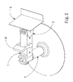
- FIG. 2 is a perspective view of the invention according to the embodiment shown in FIG. 1 ;
- FIG. 3 is a partial enlarged sectional view according to the embodiment shown in FIG. 1 ;
- FIG. 4 is a partial enlarged sectional view according to FIG. 3 ;
- FIG. 5 is a sectional side view of another embodiment of the anchor structure for electronic devices of the invention.
- FIGS. 1 and 2 for an embodiment of the anchor structure for electronic devices of the invention. It mainly includes a first bar 1 and a second bar 2 that are pivotally coupled together through a hinge means 3 .
- the hinge means 3 can be selectively set to a swivelable condition or a non-swivelable condition, and the first bar 1 and the second bar 2 also can be set to a corresponding swivelable condition or a non-swivelable condition.
- the first bar 1 and the second bar 2 are respectively a rod.
- the first bar 1 has a housing space 11 formed in a portion of the interior.
- the hinge means 3 includes an axle 31 hinged on one end of the first bar 1 .
- the second bar 2 is fastened to the peripheral surface of the axle 31 so that the second bar 2 can be swiveled relative to the first bar 1 through the axle 31 .
- the fastening means 4 includes a handle 41 which has a hinge portion 41 a on a bottom end corresponding to the housing space 11 and pivotally coupled with the first bar 1 .
- the hinge portion 41 a runs through the first bar 1 and fastens to a cam 42 in the housing space 11 .
- the cam 42 has a protrusive portion 42 a on one side formed in a selected surface profile.
- the housing space 11 has one end leading to where the first bar 1 being coupled with the axle 31 .
- the housing space 11 also holds a slidable brake element 43 and fastens to a spring 44 in a fixed manner on the one end.
- the spring 44 aims to keep the brake element 43 in contact with the cam 42 tightly so that turning of the cam 42 can selectively make the braking element 43 to slide away from the axle 31 or in a tight contact condition with the axle 31 to make the axle 31 in a swivelable condition or non-swivelable condition.
- the axle 31 has a teeth structure on the peripheral surface to form a teeth surface 32 .
- the brake element 4 has an end surface made from rubber corresponding to the axle 31 for pressing thereon. Hence the friction force between the brake element 43 and the teeth surface 32 can be increased.
- the pivotal coupling portion of the first bar 1 and the axle 31 also has a damping wheel 33 which has a portion of elements fastened to the first bar 1 , while other portion of the elements is fastened to the axle 31 so that when the first bar 1 swivels relative to the axle 31 the damping wheel 33 provides a damping resistance.
- the damping wheel 33 provides resistance against swiveling of the first bar 1 about axle 31 so that the second bar 2 can be firmly anchored on a selected position, and reduce the relative swiveling between the first bar 1 and the second bar 2 caused by gravity force.
- the first bar 1 may have a base 5 on other end to mount the anchor structure onto the surface of a selected object.
- the second bar 2 may have a holding dock 6 on other end to hold the electronic device so that the whole anchor structure can be mounted onto the surface of the selected object.
- the cam 42 rams the brake element 43 outwards in contact tightly with the teeth surface 32 of the axle 31 so that the axle 31 is in an anchored condition, and the first bar 1 and the second bar 2 are in the non-swivelable condition relative to each other.
- the cam 42 is released from the brake element 43 , the brake element 43 is pushed inwards by the spring 44 to escape the teeth surface 32 of the axle 31 , hence the first bar 1 and the second bar 2 are in the swivelable condition. But swiveling of the first bar 1 and second bar 2 is resisted by the damping wheel 33 and is proceeded in a slower fashion.
- the base 5 has a top end fastened to a third bar 7 .
- the first bar 1 is pivotally coupled with the top end of the third bar 7 through a second hinge means 3 ′.
- the second hinge means 3 ′ has a second axle 31 ′ pivotally coupled on one end of the first bar 1 .
- the third bar 7 is fastened to the periphery surface of the second axle 31 ′ so that the third bar 7 can be swiveled relative to the first bar 1 through the second axle 31 ′.
- the handle 41 has a hinge portion 41 a on the bottom end running through the first bar 1 and fastened to the cam 42 in the housing space 11 .
- the cam 42 has a first protrusive portion 42 a and a second protrusive portion 42 b on two opposite sides formed respectively in a selected surface profile.
- the housing space 11 has one end leading to where the first bar 1 being coupled with the axle 31 , and another end leading to where the first bar 1 being coupled with the second axle 31 ′.
- the housing space 11 further has a first brake element 43 and a second brake element 43 ′ slidable on two ends, and a first spring 44 and a second spring 44 ′ anchoring on the two ends.
- the first and second springs 44 and 44 ′ make respectively the brake elements 43 and 43 ′ in contact tightly with protrusive portions 42 a and 42 b of the cam 42 so that rotation of the cam 42 can selectively make the brake elements 43 and 43 ′ to escape the axles 31 and 31 ′, or slide to ram the axles 31 and 31 ′ tightly to allow the axles 31 and 31 ′ in a swivelable or non-swivelable condition.
- the protrusive portions 42 a and 42 b of the cam 42 ram the brake elements 43 and 43 ′ outwards in contact tightly with the teeth surface 32 of the axle 31 so that the axle 31 is in an anchored condition, and the first bar 1 and the second bar 2 are in a non-swivelable condition relative to each other. Meanwhile the second brake element 43 ′ is in contact tightly with the second teeth surface 32 ′ to anchor the second axle 31 ′.
- the first bar 1 and the third bar 7 can also be selectively set to a non-swivelable condition.
- the protrusive portions 42 a and 42 a of the cam 42 are released from the brake elements 43 and 43 ′, and the brake elements 43 and 43 ′ are pushed inwards respectively by the springs 44 and 44 ′ inwards so that the first brake element 43 escapes the teeth surfaces 32 of the axle 31 , and the first bar 1 and the second bar 2 can be selectively set in a swivelable condition relative to each other.
- the second brake element 43 ′ is moved away from the second teeth surface 32 ′ of the second axle 31 ′, and the first bar 1 and the third bar 7 can be selectively set in a swivelable condition relative to each other.
Abstract
An anchor structure for electronic devices includes a plurality of bars that are pivotally coupled through a hinged means. At least one of the bars has a housing space formed in a portion of the interior to allow the bars to be swivelable relative to one another. The anchor structure further has a fastening means which has a handle with a bottom end located in the housing space and hinged on a corresponding bar. The hinged portion on the bottom end of the handle runs through the bar and is fastened to a cam. The housing space also holds a slidable brake element corresponding to the cam and a spring to keep the brake element in contact tightly with the cam so that turning of the cam can selectively move the brake element to a position to escape the axle or to another position to form a tight contact with an axle.
Description
This application is a Divisional of application Ser. No. 11/554,875, filed on Oct. 31, 2006, now U.S. Pat. No. 7,513,473, and for which priority is claimed under 35 U.S.C. §120, the entire contents of which are hereby incorporated by reference.
1. Field of the Invention
The present invention relates to an anchor structure for electronic devices and particularly to an anchor structure that has a hinge means and a fastening means to adjust holding positions of an electronic device.
2. Description of the Prior Art
Conventional portable electronic devices such as handsets (mobile phones), PDAs, GPS (global positioning system) and the like can provide powerful communication functions, thus are widely accepted on the market. These portable electronic devices are often being installed on transportation vehicles to enable users to use during driving or riding.
In general, the conventional anchor structures, which are used to hold portable electronic devices, include a transformative bar structure or a plurality of hinged bars. Through a turning and fastening mechanism, the coupling tightness of the hinged axles can be altered, and the bars can be swiveled relative to one another about the axles or fastened, thereby to adjust the holding position to provide an optimal operating position for users. However, the stability and rigidity of the transformative bar structure are often not desirable. Swaying frequently occurs during driving. Moreover, the turning and fastening mechanism for the bars is easily loosened. It also is not convenient to use during driving and could result in hazardous conditions. There is still room for improvement.
In view of the aforesaid problems occurred to the conventional anchor structures for electronic devices, the primary object of the present invention is to provide an anchor structure to hold portable electronic devices.
Another object of the invention is to provide an anchor structure for electronic devices that has a hinge means and a fastening means. There are bars coupled through hinge axles that can be swiveled relative to one another or fastened to adjust the positions of the bars.
Yet another object of the invention is to provide an anchor structure for electronic devices that has a hinge means and a fastening means. The fastening means can simultaneously control swiveling or fastening condition of hinge axles.
To achieve the foregoing objects the anchor structure for electronic devices of the invention includes a plurality of bars that are pivotally coupled through a hinge means. At least one of the bars has a housing space to allow the bars to be swiveled relative to one another. The invention further has a fastening means which has a handle with a bottom corresponding to the housing space and hinged on a corresponding bar. The handle has a hinge portion on the bottom end running through the bar and being fastened to a cam in the housing space. The housing space further holds a slidable brake element corresponding to the cam and a spring to harness the brake element to form a tight contact with the cam. Thus the cam can be turned to selectively make the brake element to slide to a position to escape an axle or another position to form a tight contact with the axle.
The bar that has the housing space has two ends to be pivotally coupled with other bars through the hinge means. The housing space communicates the hinge means on two ends thereof. The housing space also holds one set of brake element and spring corresponding to each hinge means. The cam has two ends pushing a corresponding brake element to control coupling tightness of each hinge means. Hence the positions of bars relative to one another can be adjusted as desired. Moreover, one of the bars has a holding dock to hold an electronic device. Another bar has a base to allow the anchor structure to be mounted onto the surface of a desired object.
The foregoing, as well as additional objects, features and advantages of the invention will be more readily apparent from the following detailed description, which proceeds with reference to the accompanying drawings.
Refer to FIGS. 1 and 2 for an embodiment of the anchor structure for electronic devices of the invention. It mainly includes a first bar 1 and a second bar 2 that are pivotally coupled together through a hinge means 3. Through a fastening means 4 the hinge means 3 can be selectively set to a swivelable condition or a non-swivelable condition, and the first bar 1 and the second bar 2 also can be set to a corresponding swivelable condition or a non-swivelable condition.
Referring to FIG. 3 , the first bar 1 and the second bar 2 are respectively a rod. The first bar 1 has a housing space 11 formed in a portion of the interior. The hinge means 3 includes an axle 31 hinged on one end of the first bar 1. The second bar 2 is fastened to the peripheral surface of the axle 31 so that the second bar 2 can be swiveled relative to the first bar 1 through the axle 31. The fastening means 4 includes a handle 41 which has a hinge portion 41 a on a bottom end corresponding to the housing space 11 and pivotally coupled with the first bar 1. The hinge portion 41 a runs through the first bar 1 and fastens to a cam 42 in the housing space 11. The cam 42 has a protrusive portion 42 a on one side formed in a selected surface profile. The housing space 11 has one end leading to where the first bar 1 being coupled with the axle 31. The housing space 11 also holds a slidable brake element 43 and fastens to a spring 44 in a fixed manner on the one end. The spring 44 aims to keep the brake element 43 in contact with the cam 42 tightly so that turning of the cam 42 can selectively make the braking element 43 to slide away from the axle 31 or in a tight contact condition with the axle 31 to make the axle 31 in a swivelable condition or non-swivelable condition.
The axle 31 has a teeth structure on the peripheral surface to form a teeth surface 32. The brake element 4 has an end surface made from rubber corresponding to the axle 31 for pressing thereon. Hence the friction force between the brake element 43 and the teeth surface 32 can be increased.
The pivotal coupling portion of the first bar 1 and the axle 31 also has a damping wheel 33 which has a portion of elements fastened to the first bar 1, while other portion of the elements is fastened to the axle 31 so that when the first bar 1 swivels relative to the axle 31 the damping wheel 33 provides a damping resistance. Hence when the brake element 43 loosens the compression on the axle 31, the damping wheel 33 provides resistance against swiveling of the first bar 1 about axle 31 so that the second bar 2 can be firmly anchored on a selected position, and reduce the relative swiveling between the first bar 1 and the second bar 2 caused by gravity force.
The first bar 1 may have a base 5 on other end to mount the anchor structure onto the surface of a selected object. The second bar 2 may have a holding dock 6 on other end to hold the electronic device so that the whole anchor structure can be mounted onto the surface of the selected object.
Referring to FIGS. 3 and 4 , when the handle 41 is moved to a first condition, the cam 42 rams the brake element 43 outwards in contact tightly with the teeth surface 32 of the axle 31 so that the axle 31 is in an anchored condition, and the first bar 1 and the second bar 2 are in the non-swivelable condition relative to each other. When the handle 41 is moved to a second condition, the cam 42 is released from the brake element 43, the brake element 43 is pushed inwards by the spring 44 to escape the teeth surface 32 of the axle 31, hence the first bar 1 and the second bar 2 are in the swivelable condition. But swiveling of the first bar 1 and second bar 2 is resisted by the damping wheel 33 and is proceeded in a slower fashion.
Refer to FIG. 5 for another embodiment of the invention. The base 5 has a top end fastened to a third bar 7. The first bar 1 is pivotally coupled with the top end of the third bar 7 through a second hinge means 3′. The second hinge means 3′ has a second axle 31′ pivotally coupled on one end of the first bar 1. The third bar 7 is fastened to the periphery surface of the second axle 31′ so that the third bar 7 can be swiveled relative to the first bar 1 through the second axle 31′. The handle 41 has a hinge portion 41 a on the bottom end running through the first bar 1 and fastened to the cam 42 in the housing space 11. The cam 42 has a first protrusive portion 42 a and a second protrusive portion 42 b on two opposite sides formed respectively in a selected surface profile. The housing space 11 has one end leading to where the first bar 1 being coupled with the axle 31, and another end leading to where the first bar 1 being coupled with the second axle 31′. The housing space 11 further has a first brake element 43 and a second brake element 43′ slidable on two ends, and a first spring 44 and a second spring 44′ anchoring on the two ends. The first and second springs 44 and 44′ make respectively the brake elements 43 and 43′ in contact tightly with protrusive portions 42 a and 42 b of the cam 42 so that rotation of the cam 42 can selectively make the brake elements 43 and 43′ to escape the axles 31 and 31′, or slide to ram the axles 31 and 31′ tightly to allow the axles 31 and 31′ in a swivelable or non-swivelable condition.
When the handle 41 is moved to the first condition, the protrusive portions 42 a and 42 b of the cam 42 ram the brake elements 43 and 43′ outwards in contact tightly with the teeth surface 32 of the axle 31 so that the axle 31 is in an anchored condition, and the first bar 1 and the second bar 2 are in a non-swivelable condition relative to each other. Meanwhile the second brake element 43′ is in contact tightly with the second teeth surface 32′ to anchor the second axle 31′. The first bar 1 and the third bar 7 can also be selectively set to a non-swivelable condition. When the handle 41 is moved to the second condition, the protrusive portions 42 a and 42 a of the cam 42 are released from the brake elements 43 and 43′, and the brake elements 43 and 43′ are pushed inwards respectively by the springs 44 and 44′ inwards so that the first brake element 43 escapes the teeth surfaces 32 of the axle 31, and the first bar 1 and the second bar 2 can be selectively set in a swivelable condition relative to each other. Meanwhile the second brake element 43′ is moved away from the second teeth surface 32′ of the second axle 31′, and the first bar 1 and the third bar 7 can be selectively set in a swivelable condition relative to each other.
While the preferred embodiments of the invention have been set forth for the purpose of disclosure, modifications of the disclosed embodiments of the invention as well as other embodiments thereof may occur to those skilled in the art. Accordingly, the appended claims are intended to cover all embodiments which do not depart from the spirit and scope of the invention.
Claims (12)
1. An anchor structure for electronic devices, comprising:
a first bar which has a housing space formed in a portion of the interior thereof;
a second bar;
a hinge means which includes an axle pivotally coupled on one end of the first bar, the second bar being fastened to a peripheral surface of the axle so that the second bar is swivelable relative to the first bar through the axle; and
a fastening means having a handle which has a hinge portion on a bottom end corresponding to the housing space to be hinged on the first bar and fastened to a cam located in the housing space, the cam having a protrusive portion on one side to form a selected surface profile, the housing space holding a slidable brake element corresponding to the axle such that turning of the cam selectively moves the brake element to a position to escape the axle or another position to form a tight contact with the axle;
wherein the peripheral surface of the axle is formed with a teeth surface.
2. The anchor structure of claim 1 , wherein the housing space holds a spring corresponding to where the first bar being pivotally coupled with the axle to force the brake element to form a tight contact with the cam.
3. The anchor structure of claim 1 , wherein the brake element has one end surface made from rubber to be in contact with the axle.
4. An anchor structure for electronic devices, comprising:
a first bar which has a housing space formed in a portion of the interior thereof;
a second bar;
a hinge means which includes an axle pivotally coupled on one end of the first bar, the second bar being fastened to a peripheral surface of the axle so that the second bar is swivelable relative to the first bar through the axle; and
a fastening means having a handle which has a hinge portion on a bottom end corresponding to the housing space to be hinged on the first bar and fastened to a cam located in the housing space, the cam having a protrusive portion on one side to form a selected surface profile, the housing space holding a slidable brake element corresponding to the axle such that turning of the cam selectively moves the brake element to a position to escape the axle or another position to form a tight contact with the axle;
wherein the hinge means has a damping wheel which has a portion of elements fastened to the first bar and other portion of the elements fastened to the axle to provide a damping resistance.
5. The anchor structure of claim 4 , wherein the housing space holds a spring corresponding to where the first bar being pivotally coupled with the axle to force the brake element to form a tight contact with the cam.
6. The anchor structure of claim 4 , wherein the brake element has one end surface made from rubber to be in contact with the axle.
7. An anchor structure for electronic devices, comprising:
a first bar which has a housing space formed in a portion of the interior thereof;
a second bar;
a hinge means which includes an axle pivotally coupled on one end of the first bar, the second bar being fastened to a peripheral surface of the axle so that the second bar is swivelable relative to the first bar through the axle; and
a fastening means having a handle which has a hinge portion on a bottom end corresponding to the housing space to be hinged on the first bar and fastened to a cam located in the housing space, the cam having a protrusive portion on one side to form a selected surface profile, the housing space holding a slidable brake element corresponding to the axle such that turning of the cam selectively moves the brake element to a position to escape the axle or another position to form a tight contact with the axle;
wherein the second bar has a holding dock on other end to hold an electronic device.
8. The anchor structure of claim 7 , wherein the housing space holds a spring corresponding to where the first bar being pivotally coupled with the axle to force the brake element to form a tight contact with the cam.
9. The anchor structure of claim 7 , wherein the brake element has one end surface made from rubber to be in contact with the axle.
10. An anchor structure for electronic devices, comprising:
a first bar which has a housing space formed in a portion of the interior thereof;
a second bar;
a hinge means which includes an axle pivotally coupled on one end of the first bar, the second bar being fastened to a peripheral surface of the axle so that the second bar is swivelable relative to the first bar through the axle; and
a fastening means having a handle which has a hinge portion on a bottom end corresponding to the housing space to be hinged on the first bar and fastened to a cam located in the housing space, the cam having a protrusive portion on one side to form a selected surface profile, the housing space holding a slidable brake element corresponding to the axle such that turning of the cam selectively moves the brake element to a position to escape the axle or another position to form a tight contact with the axle;
wherein the first bar has other end fastened to a base to mount the anchor structure onto the surface of an object.
11. The anchor structure of claim 10 , wherein the housing space holds a spring corresponding to where the first bar being pivotally coupled with the axle to force the brake element to form a tight contact with the cam.
12. The anchor structure of claim 10 , wherein the brake element has one end surface made from rubber to be in contact with the axle.
Priority Applications (1)
| Application Number | Priority Date | Filing Date | Title |
|---|---|---|---|
| US12/368,741 US7712722B2 (en) | 2006-10-31 | 2009-02-10 | Anchor structure for electronic devices |
Applications Claiming Priority (2)
| Application Number | Priority Date | Filing Date | Title |
|---|---|---|---|
| US11/554,875 US7513473B2 (en) | 2006-10-31 | 2006-10-31 | Anchor structure for electronic devices |
| US12/368,741 US7712722B2 (en) | 2006-10-31 | 2009-02-10 | Anchor structure for electronic devices |
Related Parent Applications (1)
| Application Number | Title | Priority Date | Filing Date |
|---|---|---|---|
| US11/554,875 Division US7513473B2 (en) | 2006-10-31 | 2006-10-31 | Anchor structure for electronic devices |
Publications (2)
| Publication Number | Publication Date |
|---|---|
| US20090146034A1 US20090146034A1 (en) | 2009-06-11 |
| US7712722B2 true US7712722B2 (en) | 2010-05-11 |
Family
ID=39462650
Family Applications (2)
| Application Number | Title | Priority Date | Filing Date |
|---|---|---|---|
| US11/554,875 Expired - Fee Related US7513473B2 (en) | 2006-10-31 | 2006-10-31 | Anchor structure for electronic devices |
| US12/368,741 Expired - Fee Related US7712722B2 (en) | 2006-10-31 | 2009-02-10 | Anchor structure for electronic devices |
Family Applications Before (1)
| Application Number | Title | Priority Date | Filing Date |
|---|---|---|---|
| US11/554,875 Expired - Fee Related US7513473B2 (en) | 2006-10-31 | 2006-10-31 | Anchor structure for electronic devices |
Country Status (1)
| Country | Link |
|---|---|
| US (2) | US7513473B2 (en) |
Cited By (1)
| Publication number | Priority date | Publication date | Assignee | Title |
|---|---|---|---|---|
| US20120248263A1 (en) * | 2011-04-02 | 2012-10-04 | Touchwerk, Inc. | Computer work desk |
Families Citing this family (6)
| Publication number | Priority date | Publication date | Assignee | Title |
|---|---|---|---|---|
| DE202005000768U1 (en) * | 2004-11-29 | 2005-03-31 | Richter Harald | Device with universally adjustable retaining plate |
| GB2450380B (en) * | 2007-06-22 | 2009-10-07 | Path Distrib Ltd | Improvements in hubs for wall mounting systems |
| US8469323B1 (en) * | 2008-04-21 | 2013-06-25 | Yani Deros | Modular monitor support assembly |
| US8978948B2 (en) | 2012-08-23 | 2015-03-17 | Duane Tujague | Global positioning system (GPS) mount |
| US9423066B2 (en) * | 2014-03-27 | 2016-08-23 | Hiwin Technologies Corp. | Support arm with a multiple degree of freedom locking device |
| US11174986B2 (en) * | 2019-01-25 | 2021-11-16 | Airwall Hangers Corporation | Joint structure for adjustably suspending equipment from a ceiling track |
Citations (7)
| Publication number | Priority date | Publication date | Assignee | Title |
|---|---|---|---|---|
| US5560682A (en) * | 1992-12-01 | 1996-10-01 | Klasse Pty Ltd | Adjustment mechanism for a chair |
| US20020053818A1 (en) * | 2000-09-21 | 2002-05-09 | G&W Products, Inc | Quick-mount & pivot base for bicycle seat or the like |
| US6769657B1 (en) | 2003-04-09 | 2004-08-03 | Min Hwa Huang | Support device for monitor, display or objects |
| US20070102607A1 (en) | 2005-11-07 | 2007-05-10 | Tuang-Hock Koh | Monitor support device |
| US7252277B2 (en) * | 2003-01-17 | 2007-08-07 | Ergotron, Inc. | Support arm |
| US7289315B2 (en) | 2001-11-08 | 2007-10-30 | Apple Inc. | Computer controlled display device |
| US20080302946A1 (en) * | 2006-07-21 | 2008-12-11 | Henryk Bury | Supporting arm with a suction cup and a holder for attaching various equipment within a mechanical linkage |
-
2006
- 2006-10-31 US US11/554,875 patent/US7513473B2/en not_active Expired - Fee Related
-
2009
- 2009-02-10 US US12/368,741 patent/US7712722B2/en not_active Expired - Fee Related
Patent Citations (7)
| Publication number | Priority date | Publication date | Assignee | Title |
|---|---|---|---|---|
| US5560682A (en) * | 1992-12-01 | 1996-10-01 | Klasse Pty Ltd | Adjustment mechanism for a chair |
| US20020053818A1 (en) * | 2000-09-21 | 2002-05-09 | G&W Products, Inc | Quick-mount & pivot base for bicycle seat or the like |
| US7289315B2 (en) | 2001-11-08 | 2007-10-30 | Apple Inc. | Computer controlled display device |
| US7252277B2 (en) * | 2003-01-17 | 2007-08-07 | Ergotron, Inc. | Support arm |
| US6769657B1 (en) | 2003-04-09 | 2004-08-03 | Min Hwa Huang | Support device for monitor, display or objects |
| US20070102607A1 (en) | 2005-11-07 | 2007-05-10 | Tuang-Hock Koh | Monitor support device |
| US20080302946A1 (en) * | 2006-07-21 | 2008-12-11 | Henryk Bury | Supporting arm with a suction cup and a holder for attaching various equipment within a mechanical linkage |
Cited By (2)
| Publication number | Priority date | Publication date | Assignee | Title |
|---|---|---|---|---|
| US20120248263A1 (en) * | 2011-04-02 | 2012-10-04 | Touchwerk, Inc. | Computer work desk |
| US10010169B2 (en) * | 2011-04-02 | 2018-07-03 | Eric Arthur Grotenhuis | Computer work desk |
Also Published As
| Publication number | Publication date |
|---|---|
| US7513473B2 (en) | 2009-04-07 |
| US20090146034A1 (en) | 2009-06-11 |
| US20080121772A1 (en) | 2008-05-29 |
Similar Documents
| Publication | Publication Date | Title |
|---|---|---|
| US7712722B2 (en) | Anchor structure for electronic devices | |
| US7748669B2 (en) | Adjustable holding frame | |
| US5060260A (en) | Mounting cradle for a portable cellular telephone | |
| CA2885699C (en) | Universal mount system for pickup truck bed | |
| US6568644B2 (en) | Clamp for a cross bar | |
| US20060208524A1 (en) | Tonneau cover system | |
| US7213731B1 (en) | Hold-down for a vehicle-mounted equipment carrier | |
| JP2892950B2 (en) | A device to fix the support rod to the car roof | |
| US20100038505A1 (en) | Portable object support | |
| CA2437055A1 (en) | Improved attachment means for facilitating user access to vehicle platforms | |
| US20060060733A1 (en) | Angle adjustable holder | |
| US7527230B2 (en) | Anchor dock equipped with a bracing rack | |
| WO2003064195A3 (en) | Rear boot hood for an open-top vehicle with a folding roof | |
| US20060060623A1 (en) | Bike carrying rack for automobile | |
| US8444102B2 (en) | Apparatus for holding handheld devices | |
| JP3127446U (en) | Fixing device | |
| FR3050703A1 (en) | SUPPORT DEVICE FOR SCREEN. | |
| KR0140151Y1 (en) | Cellular phone locking device | |
| JP2005318382A (en) | Cellular phone holder | |
| EP1700988A3 (en) | Opening and closing device of a mobile structure | |
| JP3148956U (en) | Support stand | |
| KR200220934Y1 (en) | Hands-free kit for automobile | |
| KR100792568B1 (en) | Multipurpose stand for an automobile | |
| CN213228504U (en) | Mobile terminal support | |
| FR2961765A1 (en) | DEVICE FOR SUPPORTING A PORTABLE DEVICE FOR A MOTOR VEHICLE COMPRISING A HEMISPHERIC ROD END CONNECTION |
Legal Events
| Date | Code | Title | Description |
|---|---|---|---|
| FPAY | Fee payment |
Year of fee payment: 4 |
|
| FEPP | Fee payment procedure |
Free format text: MAINTENANCE FEE REMINDER MAILED (ORIGINAL EVENT CODE: REM.) |
|
| LAPS | Lapse for failure to pay maintenance fees |
Free format text: PATENT EXPIRED FOR FAILURE TO PAY MAINTENANCE FEES (ORIGINAL EVENT CODE: EXP.) |
|
| STCH | Information on status: patent discontinuation |
Free format text: PATENT EXPIRED DUE TO NONPAYMENT OF MAINTENANCE FEES UNDER 37 CFR 1.362 |
|
| FP | Lapsed due to failure to pay maintenance fee |
Effective date: 20180511 |