US7720258B1 - Structured comparison of objects from similar images - Google Patents
Structured comparison of objects from similar images Download PDFInfo
- Publication number
- US7720258B1 US7720258B1 US11/341,938 US34193806A US7720258B1 US 7720258 B1 US7720258 B1 US 7720258B1 US 34193806 A US34193806 A US 34193806A US 7720258 B1 US7720258 B1 US 7720258B1
- Authority
- US
- United States
- Prior art keywords
- subimage
- image
- objects
- region
- recited
- Prior art date
- Legal status (The legal status is an assumption and is not a legal conclusion. Google has not performed a legal analysis and makes no representation as to the accuracy of the status listed.)
- Expired - Fee Related, expires
Links
Images


Classifications
-
- G—PHYSICS
- G06—COMPUTING; CALCULATING OR COUNTING
- G06V—IMAGE OR VIDEO RECOGNITION OR UNDERSTANDING
- G06V20/00—Scenes; Scene-specific elements
- G06V20/10—Terrestrial scenes
-
- G—PHYSICS
- G06—COMPUTING; CALCULATING OR COUNTING
- G06F—ELECTRIC DIGITAL DATA PROCESSING
- G06F18/00—Pattern recognition
- G06F18/20—Analysing
- G06F18/28—Determining representative reference patterns, e.g. by averaging or distorting; Generating dictionaries
-
- G—PHYSICS
- G06—COMPUTING; CALCULATING OR COUNTING
- G06V—IMAGE OR VIDEO RECOGNITION OR UNDERSTANDING
- G06V10/00—Arrangements for image or video recognition or understanding
- G06V10/70—Arrangements for image or video recognition or understanding using pattern recognition or machine learning
- G06V10/77—Processing image or video features in feature spaces; using data integration or data reduction, e.g. principal component analysis [PCA] or independent component analysis [ICA] or self-organising maps [SOM]; Blind source separation
- G06V10/772—Determining representative reference patterns, e.g. averaging or distorting patterns; Generating dictionaries
-
- G—PHYSICS
- G06—COMPUTING; CALCULATING OR COUNTING
- G06V—IMAGE OR VIDEO RECOGNITION OR UNDERSTANDING
- G06V40/00—Recognition of biometric, human-related or animal-related patterns in image or video data
- G06V40/10—Human or animal bodies, e.g. vehicle occupants or pedestrians; Body parts, e.g. hands
- G06V40/16—Human faces, e.g. facial parts, sketches or expressions
Definitions
- Automatic detection processes can be used to find items in an image and can be a powerful tool.
- a face detection process can detect faces of people in an image.
- digital cameras With digital cameras becoming increasingly popular, more and more digital images are being created. Face detection technology enables management of the increasing number of digital images for personal and commercial use.
- two images are similar to each other.
- a photographer may take multiple photographs of a group of people.
- a screen size may be relatively small, or a face detected in an image may be small with respect to the image. Techniques to assist users in viewing objects detected from similar images may be useful.
- FIG. 1A is a diagram illustrating an embodiment of an image and objects that are detected from the image.
- FIG. 1B is a block diagram illustrating an embodiment of a system for detecting and processing objects.
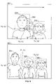
- FIG. 2 illustrates an embodiment of similar images and objects detected from those images.
- FIG. 3 is a diagram illustrating an embodiment of a display that conveys correspondences between objects detected from similar images.
- FIG. 4 is a flowchart illustrating an embodiment of determining and displaying a correspondence between two objects, each detected from similar images.
- FIG. 5 is a flowchart illustrating an embodiment of determining a correspondence between objects detected from similar images.
- FIG. 6 is a diagram illustrating an embodiment of determining correspondences between objects based on coordinates and a tolerance.
- FIG. 7 is a diagram illustrating an embodiment of determining correspondences between objects based on proximity.
- FIG. 8 is a diagram illustrating an embodiment of determining correspondences between objects based on an ordering.
- FIG. 9 is a diagram illustrating an embodiment of a display that shows corresponding objects in a two dimensional array.
- the invention can be implemented in numerous ways, including as a process, an apparatus, a system, a composition of matter, a computer readable medium such as a computer readable storage medium or a computer network wherein program instructions are sent over optical or electronic communication links.
- these implementations, or any other form that the invention may take, may be referred to as techniques.
- a component such as a processor or a memory described as being configured to perform a task includes both a general component that is temporarily configured to perform the task at a given time or a specific component that is manufactured to perform the task.
- the order of the steps of disclosed processes may be altered within the scope of the invention.
- FIG. 1A is a diagram illustrating an embodiment of an image and objects that are detected from the image.
- image 100 may be a file in a variety of formats, including Joint Photographic Experts Group (JPEG), Graphics Interchange Format (GIF), Tagged Image File Format (TIFF), and Portable Network Graphics (PNG).
- JPEG Joint Photographic Experts Group
- GIF Graphics Interchange Format
- TIFF Tagged Image File Format
- PNG Portable Network Graphics
- image 100 is generated using a digital camera.
- images may be described in the examples herein, any visual data (including video, streaming video, and graphical data) may be used in various embodiments.
- Automatic detection processing is performed on image 100 .
- Automatic detection processing detects occurrences of a detection object in an image.
- Automatic detection processing may be performed using various techniques. For example, Eigenfaces, Adaboost, neural networks, may be used.
- a two dimensional pattern matching technique may be used.
- a three dimensional model of the object may be used to approximate the object.
- the detection object is a face and Adobe® Photoshop® Elements is used to perform automatic face detection.
- Objects are output by an automatic detection process and are believed by the automatic detection process to include an occurrence of the detection object.
- Automatic detection processes do not necessarily attempt to detect a particular detection object (for example, the face of a particular person). Rather, the process may attempt to detect any occurrence of a detection object in an image (for example, the face of any person).
- each object includes one and only one occurrence of a detection object. Examples of detection objects include a face, person, animal, car, boat, book, table, tree, mountain, etc.
- Objects may be associated with a subimage or a portion of an image and may be described in a variety of ways.
- objects are associated with rectangular shaped boundary.
- objects output by an automatic detection process have a non-rectangular shape, such as a round shape.
- Object 102 may be described by coordinates (x, y). Coordinates (x, y) may describe the location of the lower left corner of object 102 (i.e., the origin point of object 102 ) with respect to the origin of the image (i.e., the lower left corner of image 100 ).
- a variety of units may be used for coordinates (x, y), such as pixels or millimeters.
- Object 102 in this example is also described by a height, H, and a width, W.
- objects output by an automatic detection process have a fixed aspect ratio (i.e., a fixed width to height ratio).
- a fixed aspect ratio i.e., a fixed width to height ratio
- Additional information associated with each object may be output by an automatic detection process.
- a probability that a given object includes an occurrence of the detection object is output.
- a face detection process may generate a probability that object 106 includes a face.
- one or more angles are output by an automatic detection process.
- An angle may be associated with an orientation, rotation, or tilt of the occurrence of the detection object. For example, one angle may describe the tilt of the face with respect to a vertical axis. Another angle may describe the rotation of the face.
- Automatic detection processes can be imperfect. Sometimes, an automatic detection process may not be able to detect an occurrence of a detection object. For example, some face detection processes may not be able to detect the face of a person if the face is too small in an image. An automatic detection process can also generate “false alarms.” A face detection process may output an object that does not include a face.
- subsequent processing may be performed on an image or an associated object after automatic detection processing.
- automatic object identification is performed.
- a face identification process may be performed where detected objects are evaluated to determine whether the objects contain the face of a particular person. Identification may be performed using various techniques. For example, a technique based on Adaboost, Linear Discriminant Analysis (LDA), or principal component analysis (PCA) may be used to perform object identification.
- LDA Linear Discriminant Analysis
- PCA principal component analysis
- an automatic matching process is performed. For example, a face matching process is performed, where multiple objects from multiple images are compared and similar faces are matched together. This may improve confidence in compared regions across images.
- Object detection may be automatic or manual. For example, a user may have drawn a box around any of faces 102 , 104 , and 106 to detect a face.
- the output of a manual detection process may include the same information as the output of an automatic detection process.
- the probability that a manually detected object includes the detection object may be set to 1.
- objects obtained using a manual detection process are normalized. For example, manually detected objects may be normalized to match the aspect ratio of automatically detected objects. In some cases, all of the manually detected objects are normalized to a standard parameter or scale. In some embodiments, a normalization process to conform all objects to a standardized size is based on various parameters.
- Table 1 lists examples of information that may be stored for various objects. This information may be output by an object detector. In this example, objects 1-5 were automatically detected and object 6 was manually detected. Such information may be stored in one or more of a database, file metadata, file, or in any other appropriate way.
- FIG. 1B is a block diagram illustrating an embodiment of a system for detecting and processing objects.
- system 150 includes object detector 152 , object identifier 154 , and object manager 156 .
- Data 158 is input to object detector 152 .
- Data 158 may include an image, video, audio clip, and/or other data.
- Object detector 152 performs an object detection process to detect occurrences of detection objects in data 158 .
- Object detector 152 may detect any occurrence of a detection object (e.g., any face).
- Object detector 152 provides detected objects 162 as output.
- Objects 162 are provided as input to object identifier 154 , which identifies detection objects.
- object detector 152 may detect any face, and object identifier 154 may identify the face as belonging to a specific person.
- Object identifier may output one or more names associated with one or more of objects 162 .
- object identifier 154 assigns a tag (such as the tag “Bob”) to an object.
- Objects 162 and the output of object identifier 154 are provided as input to object manager 156 .
- User input 164 may also be provided as input to object manager 156 .
- Object manager 156 manages objects 162 , including organizing, tagging, and displaying information associated with objects 162 on display 160 .
- object manager 156 may determine correspondences between objects detected from similar images.
- Object manager 156 may manage the display of corresponding objects and other information.
- FIG. 2 illustrates an embodiment of similar images and objects detected from those images.
- images 200 and 202 are similar to each other and depict some items in common, in this case the three people shown.
- a photographer may have taken multiple shots and generated similar images 200 and 202 ; or, two photographers may have taken photographs of the same scene.
- Objects 204 and 205 are associated with image 200
- objects 206 - 208 are associated with image 202 .
- an automatic detection process detects all of the objects.
- at least one of the objects is manually detected.
- a user may examine an image, detect an occurrence of a detection object, and specify the portion of the image associated with the new object.
- a user may prefer image 202 over image 200 because the person depicted in object 204 is blinking. Furthermore, the person depicted in the middle of image 200 is partially blocked and there is no object associated with his face. In image 202 , none of the people are blinking, looking away from the camera, or are blocked and all of the faces depicted are associated with an object.
- a user indicates that two or more images are similar.
- a user may view a collection and select similar images from the collection.
- similar images are identified automatically.
- a process may evaluate images in a collection and identify images in the collection that are similar to each other.
- the process may be passed an input image and the process identifies other images that are similar to the input image.
- Information that a process may use in identifying similar images include time/date information. For example, a photographer may take multiple shots of a scene. The time and date of the images may be close to each other, for example on the order of a few seconds (perhaps in the case of action shots of sports scenes) or a minute (perhaps in the case of a group photograph).
- other information associated with the images is compared. For example, lighting or colors depicted in the images or tags assigned to the object or the image may be used to identify similar images.
- a user may be able to select the best overall image. For example, by viewing such a display, a user may be able to determine that the man depicted in object 204 is blinking whereas the man in object 206 is not blinking. A user may be able to determine that image 202 is preferable compared to image 200 . In some embodiments, not all of the objects associated with similar images are displayed. In some embodiments, a display conveys that object 207 has no corresponding object. The correspondence can be displayed in a structured manner (for example in a row, a column, or a two dimensional array).
- Displaying objects as described may be useful if there are many objects associated with an image, or the occurrence of a detection object is small within an image. For example, in a group photograph there may be many detected objects and/or the dimensions of the detected objects may be quite small. It may be difficult for a user to see how people (or other detection object, depending upon the embodiment) are depicted.
- Displaying objects as described may be used for a variety of other functions besides selecting a best overall image.
- a user may want to review the performance of an automatic detection process. By conveying correspondence(s) between objects, a user may realize that the man depicted in the middle of image 200 is undetected. A user may subsequently rerun the automatic detection process with difference performance parameters (for example, improved performance at the expense of processing time), or may manually detect the man in the middle by drawing a box around his face or performing another appropriate sequence of inputs associated with manual detection.
- one or more of the displayed objects is selected and some action is performed on the selected object(s). For example, a user may want to save the best object from each group of corresponding objects. Of objects 204 and 206 , object 206 may be selected to be saved since the man depicted in object 206 is not blinking The selected object may be saved to a file, such as a face book, or a library used to store objects. In some embodiments, an image may be given a ranking to allow for rating an overall image, based on objects selected. In some embodiments, a new, composite image is generated. It may be that all of the similar images contain at least one undesirable or unflattering depiction. For example, the girl depicted in object 208 may be looking away from the camera. A new composite image based on image 202 with object 205 used in place of object 208 may be created. An image with an undesirable depiction, such as image 200 , can be selected and deleted by a user. Deleting an image may delete objects associated with that image.
- object 204 , object 206 , and a corresponding object in the third image may be displayed with their correspondence conveyed by the display.
- FIG. 3 is a diagram illustrating an embodiment of a display that conveys correspondences between objects detected from similar images.
- all objects detected from images 302 and 304 are presented in display 300 .
- Objects 306 and 307 are detected from image 302
- objects 310 - 312 are detected from image 304 .
- Each object is displayed in the same row as its associated image.
- Groups of corresponding objects are displayed in the same column where the vertical alignment of objects indicates which object(s) a given object corresponds to.
- Corresponding objects 306 and 310 are displayed in the same column
- object 311 has no corresponding object and is displayed in its own column with an empty region above it
- corresponding objects 307 and 312 are displayed in the same column.
- Objects may be substantially aligned, since the human eye may not be able to discern deviations in alignment. For example, a user may not be able to detect if objects 307 and 312 deviate from a line if the deviation is on the order of a few millimeters.
- the scale may depend upon the display size of the objects. Note that display size refers to the dimensions of an object in a display such as display 300 , as opposed to the dimensions of an object within the context of its image. Objects with relatively large display sizes may be substantially aligned even if they deviate from a line by more than a few millimeters.
- the orientation is reversed.
- Objects that correspond to each other are displayed in the same row.
- Each image and its objects are displayed in the same column.
- multiple groups of corresponding objects share a column.
- object 311 may be displayed in the same column as objects 306 and 310 .
- not all objects detected from similar images are displayed. For example, some displays may only present objects 306 and 310 . In some embodiments, all objects that have at least one corresponding object are displayed. Objects 306 , 307 , 310 and 312 may be displayed, but object 311 may not necessarily be displayed. In some embodiments, an object is not displayed because of its position or location with respect to other objects and/or the dimensions of the object compared to the dimensions of other objects. For example, in image 100 , the man depicted in object 104 is not intended to be part of the picture.
- object 104 is not displayed because it is located relatively far away from objects 102 and 106 , it is located on the edge of image 100 , and/or the dimensions (e.g., the height and/or width) of object 104 are relatively small compared to the dimensions of objects 102 and 106 .
- objects 306 , 307 , and 310 - 312 are normalized and displayed as the same size, even though they may not necessarily have the same dimensions. Different dimensions may result from the photographer moving, the people depicted moving, or different zoom settings of the camera.
- objects are not normalized. For example, a user may care more about certain objects. It may be difficult to perceive that a person depicted in an object with very small dimensions is blinking or looking away, such as object 104 in image 100 . A user may care more about how people are depicted in objects with larger dimensions, such as objects 102 and 106 . Larger objects can be displayed larger than objects with smaller dimensions. This may be particularly useful if the images from which the objects are detected are not displayed.
- corresponding objects across images a normalized in a common manner.
- objects 306 and 310 may be normalized and displayed as the same size.
- Objects 307 and 312 may also be normalized and displayed as the same size, although not necessarily the same size as objects 306 and 310 .
- a given object associated with a first image corresponds to at most one object associated with a second image.
- a given object associated with the second image corresponds to at most one object associated with the first image. If a given object is not associated with any other object, the restriction is satisfied. In some embodiments, there is no such restriction.
- object 306 may correspond to both objects 310 and 311 .
- the ordering of the objects in display 300 in this example follows the placement of objects within the associated image. For example, the objects going from left to right along the top row of display 300 are: object 306 and object 307 . This ordering follows the placement of those objects in image 302 . Similarly, objects 310 - 312 are displayed in the same ordering as in image 304 . In some embodiments, objects are displayed in a different order. In one example, objects are displayed according to a confidence or a probability that a given correspondence is correct. Objects that do not correspond to any other object may be displayed at one end.
- the objects along the top row going from left to right may be: object 307 , object 306 , an empty region, and image 302 .
- the bottom row going from left to right may be: object 312 , object 310 , object 311 , and image 304 .
- the ordering may also be reversed.
- visual effects are used in display 300 .
- a unique visual effect can be used for each group of corresponding objects.
- a border in a first color can be used for corresponding objects 306 and 310 , a second color for object 311 , and a third color for corresponding objects 307 and 312 .
- lines are used to connect corresponding objects.
- Visual effects in some embodiments can be applied to the rectangles displayed in images 302 and 304 .
- the rectangles corresponding to objects 306 and 310 may have a border in a first color.
- the visual effect is a time varying effect, where an object or a border associated with an object blinks, pulsates, or changes color/shape over time.
- Display 300 in some embodiments may be incorporated into a user interface.
- a user interface which includes display 300 may have buttons, toolbars, or pull down menus which may be used to perform a variety of actions. For example, a user may select object 310 and apply a tag with a tag word of “Bob.” A user may select image 302 and delete it. Objects 306 and 307 which are associated with image 302 may also be deleted if image 302 is deleted or omitted. Object 311 may be a desirable depiction of the person, and a user may select and save object 311 to a new file. A user may be able to add another image to display 300 using a user interface.
- the new image may be specified using the user interface and objects associated with the new image may be evaluated and added to an appropriate column based on which objects they correspond to.
- a user may be able to cause display 300 to stop displaying some objects or images.
- a user may be able to manipulate the placement of objects or images in display 300 . For example, a user may be able to move object 311 to the empty region between objects 306 and 307 , or move image 304 to the left of object 310 .
- all objects in that group may be moved. For example, if a user selects and moves object 306 , object 310 may follow so that the same relative positioning and distance is maintained between objects 306 and 310 .
- Display 300 may in some cases be presented some time after processing to determine corresponding objects is performed.
- a process may store information that indicates which objects correspond to each other. This information may be stored as metadata with the file, in a table, in a database, or any other appropriate storage. Some time after the process is performed, the stored information may be retrieved and display 300 may be presented to a user. In some embodiments, display 300 is presented on a different device than the device that determined corresponding objects. For example, information that indicates which objects correspond to each other may be stored by a first device as metadata with an image file. The image file (including the metadata) may be transferred to a second device. The second device may retrieve the metadata and display corresponding objects using a display such as display 300 .
- images 302 and 304 are not displayed or are displayed slightly differently.
- the size of display 300 may be limited in some applications, in which case images 302 and 304 may not necessarily be displayed.
- images 302 and 304 are displayed without rectangles indicating the boundaries of objects.
- one or more of the objects can be selected. Rectangles in some embodiments are only displayed for those objects that are selected, if any. Unselecting an object may cause the associated rectangle to be removed from its associated image.
- FIG. 4 is a flowchart illustrating an embodiment of determining and displaying a correspondence between two objects, each detected from similar images.
- the process may be used to determine which objects correspond to each other, such as objects 306 and 310 , and display the corresponding objects.
- this example describes determining and displaying a single group of corresponding objects, multiple groups of corresponding images may be determined. In some embodiments, objects from three or more similar images are evaluated.
- a first set of one or more objects that have been detected from a first image and a second set of one or more objects that have been detected from a second image are received.
- unique object identifiers may be obtained at 400 .
- a unique object identifier may be used to locate an object and/or obtain information associated with the objects. For example, information resulting from an automatic detection process may be stored in a database, library, table, or other suitable storage method, and the object identifier may be used to retrieve this information.
- the first and second images may be similar to each other.
- the first and second images are identified by a user.
- the first and second images are automatically identified. Similar images may, for example, be characterized by similar colors in corresponding regions of an image, the number of objects, and/or the coordinates of objects. An automatic image matching process may attempt to identify similar images using these or other characteristics.
- tags (assigned to an object or an image) or the time at which an image is created may be used to determine if two images are similar to each other.
- a first member of the first set corresponds to a second member of the second set.
- spatial information associated with the objects s used to determine a correspondence between objects. Spatial information may include location or position information, such as an object's coordinates, or the size or dimensions of an object.
- a correspondence is determined by an object matching process, such as a face matching process.
- objects are identified using an object identification process. Objects that are identified to be the face of the same person may be determined to correspond.
- the first member and the second member are displayed at 404 , arranged such that the correspondence between the first member and the second member is conveyed.
- correspondence between objects is displayed by the vertical alignment of corresponding objects.
- FIG. 5 is a flowchart illustrating an embodiment of determining a correspondence between objects detected from similar images.
- the process may be used to perform 402 of the previous example.
- Objects detected from two or more similar images may be processed.
- one of the images is selected to be the reference image, where the reference image has the most number of objects. For example, image 202 has three objects associated with it, whereas image 200 has two objects associated with it.
- Image 202 is selected to be the reference image.
- the comparison set of objects, associated with the next comparison image is at 502 compared to the reference set of objects, associated with the reference image.
- objects 204 and 205 comprise the comparison set of objects
- objects 206 - 208 comprise the reference set of objects. Spatial information associated with the objects may be used in the comparison.
- a correspondence is determined such that each member of the comparison set of objects is associated with one member of the reference set of objects.
- a given reference object corresponds to a comparison object
- that reference object may be removed from consideration.
- the remaining reference objects are used in determining subsequent correspondences.
- an image or an object may have a designation of “reference” or “comparison,” the designations do not necessarily affect placement within a display.
- the output of the process illustrated may comprise solely of the correspondences between objects. Information identifying a particular image or object as “reference” or “comparison” may be discarded at the end of the process.
- spatial information is used in steps 502 and 504 to compare objects and determine a correspondence.
- the following figures illustrate some embodiments of using spatial information to determine a correspondence.
- FIG. 6 is a diagram illustrating an embodiment of determining correspondences between objects based on coordinates and a tolerance.
- image 600 is a comparison image and image 602 is a reference image.
- Image 602 is selected to be the reference image since it has the most number of objects associated with it.
- Reference objects 604 - 606 are associated with image 602 and the coordinates of the reference objects are used to determine correspondences.
- the coordinates (x 0 , y 0 ), (x 1 , y 1 ), and (x 2 , y 2 ) describe the location of the lower left corner of reference objects 604 - 606 with respect to the origin of image 602 .
- correspondences are determined using a single dimension.
- the x coordinates are obtained for the reference objects, and a range of values (x ⁇ ) through (x+ ⁇ ) is defined for each reference object. If the x coordinate of a comparison object falls within one of the ranges, a correspondence is determined between that comparison object and the reference object.
- comparison objects 608 and 609 have coordinates (x 3 , y 3 ) and (x 4 , y 4 ), respectively.
- the x coordinate of comparison object 608 , x 3 falls within the range (x 0 ⁇ ) through (x 0 + ⁇ ). A correspondence between object 608 and object 604 is therefore determined.
- the x coordinate of comparison object 609 , x 4 falls within the range of (x 2 ⁇ ) through (x 2 + ⁇ ) and a correspondence between objects 609 and 606 is declared.
- the x coordinate of no object falls within the range associated with object 605 , so no object is determined to correspond to object 605 .
- ⁇ may be referred to as a tolerance and may be used to account for location differences of objects between similar images. For example, a photographer may have taken images 600 and 602 . Between capture of the images, the photographer may move the camera or adjust the camera's zoom setting. Alternatively, the people depicted in images 600 and 602 may have moved between capture of the images. A tolerance may be used to account for these changes between similar images.
- the tolerance value used may depend on a variety of factors. In some embodiments, a fixed tolerance value is used. In some embodiments, the value of ⁇ is based on the number of objects associated with the reference image and/or the comparison image. In some embodiments, multiple tolerance values are used; a range of (x ⁇ ⁇ ) through (x+ ⁇ + ) may be defined. In some embodiments, a tolerance value is based on one or more of the coordinates. For example, image 602 may be divided into adjacent, non-overlapping rows that encompass all of image 602 . Three ranges of: the left hand edge of image 602 through
- x 1 + x 2 2 through the right hand edge of image 602 may be defined.
- very consistent coordinates may result from certain similar images.
- images generated by a photographer using a tripod may have objects with very consistent coordinates.
- a tolerance value in some embodiments is based on an average or median difference between a reference object's coordinates and a comparison object's coordinates.
- tolerance varies in accordance with a size or dimension. For example, a small object may have a smaller tolerance than a larger object.
- comparison objects there may be some comparison objects for which no correspondence is determined, perhaps because that comparison object did not fall into any of the ranges. Additional processing may be performed on those remaining comparison objects to determine correspondences for them. In some cases, two comparison objects (associated with the same comparison image) may correspond to the same reference object, or a given comparison object may correspond to multiple reference objects. In some embodiments, additional processing is performed to resolve these issues.
- One of the other techniques that use spatial information or another technique may be used.
- FIG. 7 is a diagram illustrating an embodiment of determining correspondences between objects based on proximity. In the example shown, correspondences are determined based on which reference object is closest to a given comparison object. Image 702 is selected to be the reference image since it has the most objects associated with it.
- Comparison object 708 has coordinates (x 3 , y 3 ).
- the reference object with the closest x coordinate to comparison object 708 is determined to correspond to it. This may be performed by finding the minimum difference between x coordinates: min(
- the x coordinate of reference object 704 , x 0 is the closest in value to x 3 (the x coordinate of comparison object 708 ) and a correspondence between objects 708 and 704 is determined.
- comparison object 709 The same process may be performed for comparison object 709 .
- x 4 the x coordinate of comparison object 709
- the x coordinate x 2 is closest in value to x 4 , so a correspondence between objects 709 and 706 is determined.
- geo-positioning data and/or depth information may be used to determine corresponding objects.
- two comparison objects may map to the same reference object.
- subsequent processing may be performed to resolve any conflicts.
- a process that uses spatial information is subsequently performed.
- another technique such as an object matching process is performed.
- FIG. 8 is a diagram illustrating an embodiment of determining correspondences between objects based on an ordering.
- image 800 and image 802 have the same number of objects associated with them.
- Image 802 is selected to be the reference image, although in some cases image 800 may be selected as the reference image.
- Correspondences are determined between objects based on the horizontal ordering of objects. That is, the leftmost comparison object, object 808 in this example, corresponds to the leftmost reference object, object 804 .
- the next comparison object, object 809 corresponds to reference object 805 and the rightmost comparison object, object 810 , corresponds to reference object 806 .
- determining a correspondence based on an ordering is used when there are an equal numbers of objects. In such cases, if there are an unequal numbers of objects, another method is used to determine correspondences.
- an initial process may be used to determine initial correspondences, and a second process may be performed subsequently.
- a subsequent process evaluates all objects and correspondences determined by an initial process.
- a subsequent process evaluates a subset of objects or correspondences. For example, comparison and reference objects without a corresponding object, and/or conflicting correspondences are passed to a subsequent process.
- an object matching process is used to determine a correspondence between objects.
- a face matching process may be used to examine objects and determine which objects contain similar or matching faces.
- a face matching process is relied upon solely to determine correspondences between objects.
- a face matching process is used in combination with another method, such as using spatial information, to determine correspondences between objects.
- coordinates are used to determine an initial correspondence. The correspondences may be verified by the face matching process, and/or the face matching process may be used to resolve any conflicts that may result from using spatial information.
- FIG. 9 is a diagram illustrating an embodiment of a display that shows corresponding objects in a two dimensional array.
- the images 900 and 902 are similar to each other and contain some people in common. Techniques described above to determine correspondences may be used.
- image 904 may be selected as a reference image and spatial information associated with the objects may be used to determine correspondences.
- Corresponding objects may be determined based on x and/or y coordinates.
- the closest reference object in an x-y plane may correspond to a given comparison object.
- reference image 904 and comparison image 902 are divided into identical grids. A reference object and a comparison object in the same square of the grid as may correspond to each other.
- Objects 906 - 908 are detected from image 902
- objects 910 - 913 are detected from image 904 .
- the placement of an object in the two dimensional array indicates the correspondence between objects.
- Objects 906 and 911 correspond to each other and are both in the top row, right column of their respective two dimensional arrays.
- Corresponding objects are placed in the same position.
- Objects 907 and 912 correspond to each other, and objects 908 and 913 correspond to each other.
- Object 910 does not correspond to any object in image 902 , and an empty region is displayed in the top row, left column to indicate that no object corresponds to object 910 .
- a display may vary from that of display 900 .
- objects 906 - 908 and objects 910 - 913 may have colored borders.
- a unique color may be used for each group of corresponding objects.
- a first color may be used for corresponding objects 906 and 911 , a second color for corresponding objects 907 and 912 , etc.
- a different alignment is used for the objects.
- objects 906 , 910 , and 911 may be shifted to the right.
- Object 910 would no longer be displayed between objects 907 and 912
- object 911 would no longer be displayed between objects 908 and 913 .
- a two dimensional array is used to display corresponding objects even if an image does not necessarily suggest a multi-row arrangement.
- the images may be two group photographs where all of the people are approximately the same height and are standing next to each other.
- the width of a display may be narrow.
- a two dimensional array may be used to display corresponding objects, even though the objects in the image are substantially in a single row. As the display becomes narrower, the number of objects displayed per row may decrease, and the number of objects displayed per column may increase.
Abstract
Description
| TABLE 1 | |||||||||
| Source | P(Object = | Date | User or | Date/time | |||||
| Object | File | Coordinates | Detection | Object | Auto | of image | |||
| ID | ID | of Origin | Width | Height | Angle | Object) | Detected | Detected | |
| 1 | 1 | x0, y0 | 5 | 8 | 0 | 0.8 | 1/1/05 | Auto | 12/16/04 |
| 2 | 1 | x1, y1 | 5 | 7 | 0 | 0.7 | 1/1/05 | Auto | 12/16/04 |
| 3 | 1 | x2, |
1 | 1 | 0 | 0.5 | 1/1/05 | Auto | 12/16/04 |
| 4 | 2 | x3, y3 | 2 | 2 | 10 | 0.6 | 11/2/05 | Auto | 7/10/04 |
| 5 | 2 | x4, y4 | 3 | 4 | 20 | 0.7 | 11/2/05 | Auto | 7/10/04 |
| 6 | 2 | x5, |
1 | 1 | 0 | 1 | 11/22/05 | User | 7/10/04 |
through
and
through the right hand edge of
Claims (24)
Priority Applications (1)
| Application Number | Priority Date | Filing Date | Title |
|---|---|---|---|
| US11/341,938 US7720258B1 (en) | 2006-01-26 | 2006-01-26 | Structured comparison of objects from similar images |
Applications Claiming Priority (1)
| Application Number | Priority Date | Filing Date | Title |
|---|---|---|---|
| US11/341,938 US7720258B1 (en) | 2006-01-26 | 2006-01-26 | Structured comparison of objects from similar images |
Publications (1)
| Publication Number | Publication Date |
|---|---|
| US7720258B1 true US7720258B1 (en) | 2010-05-18 |
Family
ID=42166663
Family Applications (1)
| Application Number | Title | Priority Date | Filing Date |
|---|---|---|---|
| US11/341,938 Expired - Fee Related US7720258B1 (en) | 2006-01-26 | 2006-01-26 | Structured comparison of objects from similar images |
Country Status (1)
| Country | Link |
|---|---|
| US (1) | US7720258B1 (en) |
Cited By (13)
| Publication number | Priority date | Publication date | Assignee | Title |
|---|---|---|---|---|
| US20080175485A1 (en) * | 2006-08-25 | 2008-07-24 | Sony Corporation | Image processing method, image processing method program, recording medium recording image processing method program, and image processing apparatus |
| US20090307261A1 (en) * | 2008-06-05 | 2009-12-10 | Apple Inc. | Categorization of Digital Media Based on Media Characteristics |
| US20100054601A1 (en) * | 2008-08-28 | 2010-03-04 | Microsoft Corporation | Image Tagging User Interface |
| US20100054600A1 (en) * | 2008-08-28 | 2010-03-04 | Microsoft Corporation | Tagging Images With Labels |
| US20100214436A1 (en) * | 2009-02-20 | 2010-08-26 | Samsung Digital Imaging Co., Ltd. | Method of adjusting white balance of image, recording medium having program for performing the method, and apparatus applying the method |
| US20100231791A1 (en) * | 2009-03-16 | 2010-09-16 | Disney Enterprises, Inc. | System and method for dynamic video placement on a display |
| US20110299832A1 (en) * | 2010-06-02 | 2011-12-08 | Microsoft Corporation | Adaptive video zoom |
| US20120062728A1 (en) * | 2009-05-21 | 2012-03-15 | Honda Motor Co., Ltd. | Surface inspecting device |
| WO2016013885A1 (en) * | 2014-07-25 | 2016-01-28 | Samsung Electronics Co., Ltd. | Method for retrieving image and electronic device thereof |
| JP2017117139A (en) * | 2015-12-24 | 2017-06-29 | キヤノンマーケティングジャパン株式会社 | Information processing unit, control method, program |
| US9830567B2 (en) | 2013-10-25 | 2017-11-28 | Location Labs, Inc. | Task management system and method |
| EP3282686A1 (en) * | 2016-08-11 | 2018-02-14 | LG Electronics, Inc. | Mobile terminal and operating method thereof |
| JP2019075130A (en) * | 2018-11-22 | 2019-05-16 | キヤノンマーケティングジャパン株式会社 | Information processing unit, control method, program |
Citations (70)
| Publication number | Priority date | Publication date | Assignee | Title |
|---|---|---|---|---|
| US4651146A (en) | 1983-10-17 | 1987-03-17 | International Business Machines Corporation | Display of multiple data windows in a multi-tasking system |
| US5943093A (en) | 1996-09-26 | 1999-08-24 | Flashpoint Technology, Inc. | Software driver digital camera system with image storage tags |
| US5963203A (en) | 1997-07-03 | 1999-10-05 | Obvious Technology, Inc. | Interactive video icon with designated viewing position |
| US6182069B1 (en) | 1992-11-09 | 2001-01-30 | International Business Machines Corporation | Video query system and method |
| US6324555B1 (en) | 1998-08-31 | 2001-11-27 | Adobe Systems Incorporated | Comparing contents of electronic documents |
| US20010053292A1 (en) | 2000-06-14 | 2001-12-20 | Minolta Co., Ltd. | Image extracting apparatus and image extracting method |
| US6366296B1 (en) | 1998-09-11 | 2002-04-02 | Xerox Corporation | Media browser using multimodal analysis |
| US20020074398A1 (en) | 2000-09-29 | 2002-06-20 | Lancos Kenneth J. | System and method for making monetary transactions within a coverage area |
| US20020103813A1 (en) | 2000-11-15 | 2002-08-01 | Mark Frigon | Method and apparatus for obtaining information relating to the existence of at least one object in an image |
| US20030023754A1 (en) | 2001-07-27 | 2003-01-30 | Matthias Eichstadt | Method and system for adding real-time, interactive functionality to a web-page |
| US20030033296A1 (en) | 2000-01-31 | 2003-02-13 | Kenneth Rothmuller | Digital media management apparatus and methods |
| US20030210808A1 (en) | 2002-05-10 | 2003-11-13 | Eastman Kodak Company | Method and apparatus for organizing and retrieving images containing human faces |
| US20040008906A1 (en) | 2002-07-10 | 2004-01-15 | Webb Steven L. | File management of digital images using the names of people identified in the images |
| US20040017930A1 (en) | 2002-07-19 | 2004-01-29 | Samsung Electronics Co., Ltd. | System and method for detecting and tracking a plurality of faces in real time by integrating visual ques |
| US6714672B1 (en) * | 1999-10-27 | 2004-03-30 | Canon Kabushiki Kaisha | Automated stereo fundus evaluation |
| US20040064455A1 (en) | 2002-09-26 | 2004-04-01 | Eastman Kodak Company | Software-floating palette for annotation of images that are viewable in a variety of organizational structures |
| US20040060976A1 (en) | 2002-09-27 | 2004-04-01 | Eastman Kodak Company | Trusted shipper seal tag with steganographic authentication |
| US6728728B2 (en) | 2000-07-24 | 2004-04-27 | Israel Spiegler | Unified binary model and methodology for knowledge representation and for data and information mining |
| US20040101212A1 (en) | 2002-11-25 | 2004-05-27 | Eastman Kodak Company | Imaging method and system |
| US20040204635A1 (en) | 2003-04-10 | 2004-10-14 | Scharf Tom D. | Devices and methods for the annotation of physiological data with associated observational data |
| US20040267612A1 (en) | 2003-06-30 | 2004-12-30 | Eric Veach | Using enhanced ad features to increase competition in online advertising |
| US20050013488A1 (en) | 2002-07-26 | 2005-01-20 | Manabu Hashimoto | Image processing apparatus |
| US20050011959A1 (en) | 2003-06-25 | 2005-01-20 | Grosvenor David Arthur | Tags and automated vision |
| US20050025376A1 (en) | 2003-07-31 | 2005-02-03 | Canon Kabushiki Kaisha | Image processing apparatus and method therefor |
| US20050041114A1 (en) | 2003-08-15 | 2005-02-24 | Fuji Photo Film Co., Ltd. | Image processing apparatus, method and program |
| US20050046730A1 (en) | 2003-08-25 | 2005-03-03 | Fuji Photo Film Co., Ltd. | Digital camera |
| US20050050027A1 (en) | 2003-09-03 | 2005-03-03 | Leslie Yeh | Determining and/or using location information in an ad system |
| US20050063568A1 (en) | 2003-09-24 | 2005-03-24 | Shih-Ching Sun | Robust face detection algorithm for real-time video sequence |
| US6879709B2 (en) | 2002-01-17 | 2005-04-12 | International Business Machines Corporation | System and method for automatically detecting neutral expressionless faces in digital images |
| US20050105779A1 (en) * | 2002-03-29 | 2005-05-19 | Toshio Kamei | Face meta-data creation |
| US20050117870A1 (en) | 2003-11-18 | 2005-06-02 | Bor-Ying Lee | Method and system for processing background and item data for photographic files |
| US20050129276A1 (en) | 2003-12-11 | 2005-06-16 | Haynes Simon D. | Object detection |
| US20050128221A1 (en) | 2003-12-16 | 2005-06-16 | Canon Kabushiki Kaisha | Image displaying method and image displaying apparatus |
| US20050147302A1 (en) | 2003-11-14 | 2005-07-07 | Fuji Photo Film Co., Ltd. | Methods and apparatus for object recognition using textons |
| US20050157952A1 (en) | 2003-11-26 | 2005-07-21 | Canon Kabushiki Kaisha | Image retrieval apparatus and method, and image display apparatus and method thereof |
| US20050172215A1 (en) | 2004-01-30 | 2005-08-04 | Hewlett-Packard Development Company, L.P. | Physical object with memory tags and apparatus for writing and using such objects |
| US6940545B1 (en) * | 2000-02-28 | 2005-09-06 | Eastman Kodak Company | Face detecting camera and method |
| US20050196069A1 (en) | 2004-03-01 | 2005-09-08 | Fuji Photo Film Co., Ltd. | Method, apparatus, and program for trimming images |
| US20050207630A1 (en) | 2002-02-15 | 2005-09-22 | The Regents Of The University Of Michigan Technology Management Office | Lung nodule detection and classification |
| US20050213793A1 (en) | 2004-03-23 | 2005-09-29 | Takashi Oya | Monitoring system and setting method for the same |
| US20050285943A1 (en) | 2002-06-21 | 2005-12-29 | Cutler Ross G | Automatic face extraction for use in recorded meetings timelines |
| US20060008152A1 (en) | 1999-10-08 | 2006-01-12 | Rakesh Kumar | Method and apparatus for enhancing and indexing video and audio signals |
| US20060008145A1 (en) | 2004-07-06 | 2006-01-12 | Fuji Photo Film Co., Ltd. | Image data processing apparatus and method, and image data processing program |
| US20060032916A1 (en) | 2004-08-13 | 2006-02-16 | Mueller Robert E | Remote crane bar code system |
| US20060053364A1 (en) | 2004-09-08 | 2006-03-09 | Josef Hollander | System and method for arbitrary annotation of web pages copyright notice |
| US20060050934A1 (en) | 2004-09-08 | 2006-03-09 | Fuji Photo Film Co., Ltd. | Image search apparatus and method |
| US20060071942A1 (en) | 2004-10-06 | 2006-04-06 | Randy Ubillos | Displaying digital images using groups, stacks, and version sets |
| US20060098737A1 (en) * | 2002-12-20 | 2006-05-11 | Koninklijke Philips Electronics N.V. | Segment-based motion estimation |
| US20060120572A1 (en) | 2001-12-08 | 2006-06-08 | Microsoft Corporation | System and method for multi-view face detection |
| US20060140455A1 (en) | 2004-12-29 | 2006-06-29 | Gabriel Costache | Method and component for image recognition |
| US20060161588A1 (en) | 2003-09-26 | 2006-07-20 | Nikon Corporation | Electronic image filing method, electronic image filing device and electronic image filing system |
| US20060171573A1 (en) | 1997-08-28 | 2006-08-03 | Rogers Steven K | Use of computer-aided detection system outputs in clinical practice |
| US20060222243A1 (en) * | 2005-04-02 | 2006-10-05 | Newell Martin E | Extraction and scaled display of objects in an image |
| US20060251338A1 (en) | 2005-05-09 | 2006-11-09 | Gokturk Salih B | System and method for providing objectified image renderings using recognition information from images |
| US7155036B2 (en) * | 2000-12-04 | 2006-12-26 | Sony Corporation | Face detection under varying rotation |
| US7171023B2 (en) * | 2001-11-05 | 2007-01-30 | Samsung Electronics Co., Ltd. | Illumination-invariant object tracking method and image editing system using the same |
| US7171630B2 (en) * | 2001-11-06 | 2007-01-30 | Zinio Systems, Inc. | Electronic simulation of interaction with printed matter |
| US20070071323A1 (en) | 2005-09-26 | 2007-03-29 | Cognisign Llc | Apparatus and method for processing user-specified search image points |
| US20070081744A1 (en) | 2005-05-09 | 2007-04-12 | Gokturk Salih B | System and method for use of images with recognition analysis |
| US20070098303A1 (en) | 2005-10-31 | 2007-05-03 | Eastman Kodak Company | Determining a particular person from a collection |
| US7274832B2 (en) * | 2003-11-13 | 2007-09-25 | Eastman Kodak Company | In-plane rotation invariant object detection in digitized images |
| US20070242856A1 (en) | 2004-06-28 | 2007-10-18 | Canon Kabushiki Kaisha | Object Recognition Method and Apparatus Therefor |
| US7343365B2 (en) | 2002-02-20 | 2008-03-11 | Microsoft Corporation | Computer system architecture for automatic context associations |
| US20080080745A1 (en) | 2005-05-09 | 2008-04-03 | Vincent Vanhoucke | Computer-Implemented Method for Performing Similarity Searches |
| US7403642B2 (en) | 2005-04-21 | 2008-07-22 | Microsoft Corporation | Efficient propagation for face annotation |
| US7477805B2 (en) | 2004-09-10 | 2009-01-13 | Fujifilm Corporation | Electronic album display system, an image grouping apparatus, an electronic album display method, an image grouping method, and a machine readable medium storing thereon a computer program |
| US20090016576A1 (en) | 2007-07-12 | 2009-01-15 | Samsung Techwin Co., Ltd. | Digital image processing apparatus, method of controlling the same, and recording medium for storing program for executing the method |
| US7519200B2 (en) * | 2005-05-09 | 2009-04-14 | Like.Com | System and method for enabling the use of captured images through recognition |
| US20090160618A1 (en) | 2005-11-17 | 2009-06-25 | Kumagai Monto H | Method to personalize consumer items for use in outdoor activities |
| US7587101B1 (en) | 2005-02-28 | 2009-09-08 | Adobe Systems Incorporated | Facilitating computer-assisted tagging of object instances in digital images |
-
2006
- 2006-01-26 US US11/341,938 patent/US7720258B1/en not_active Expired - Fee Related
Patent Citations (71)
| Publication number | Priority date | Publication date | Assignee | Title |
|---|---|---|---|---|
| US4651146A (en) | 1983-10-17 | 1987-03-17 | International Business Machines Corporation | Display of multiple data windows in a multi-tasking system |
| US6182069B1 (en) | 1992-11-09 | 2001-01-30 | International Business Machines Corporation | Video query system and method |
| US5943093A (en) | 1996-09-26 | 1999-08-24 | Flashpoint Technology, Inc. | Software driver digital camera system with image storage tags |
| US5963203A (en) | 1997-07-03 | 1999-10-05 | Obvious Technology, Inc. | Interactive video icon with designated viewing position |
| US20060171573A1 (en) | 1997-08-28 | 2006-08-03 | Rogers Steven K | Use of computer-aided detection system outputs in clinical practice |
| US6324555B1 (en) | 1998-08-31 | 2001-11-27 | Adobe Systems Incorporated | Comparing contents of electronic documents |
| US6366296B1 (en) | 1998-09-11 | 2002-04-02 | Xerox Corporation | Media browser using multimodal analysis |
| US20060008152A1 (en) | 1999-10-08 | 2006-01-12 | Rakesh Kumar | Method and apparatus for enhancing and indexing video and audio signals |
| US6714672B1 (en) * | 1999-10-27 | 2004-03-30 | Canon Kabushiki Kaisha | Automated stereo fundus evaluation |
| US20030033296A1 (en) | 2000-01-31 | 2003-02-13 | Kenneth Rothmuller | Digital media management apparatus and methods |
| US6940545B1 (en) * | 2000-02-28 | 2005-09-06 | Eastman Kodak Company | Face detecting camera and method |
| US20070183638A1 (en) | 2000-06-14 | 2007-08-09 | Minolta Co., Ltd. | Image extracting apparatus and image extracting method |
| US20010053292A1 (en) | 2000-06-14 | 2001-12-20 | Minolta Co., Ltd. | Image extracting apparatus and image extracting method |
| US6728728B2 (en) | 2000-07-24 | 2004-04-27 | Israel Spiegler | Unified binary model and methodology for knowledge representation and for data and information mining |
| US20020074398A1 (en) | 2000-09-29 | 2002-06-20 | Lancos Kenneth J. | System and method for making monetary transactions within a coverage area |
| US20020103813A1 (en) | 2000-11-15 | 2002-08-01 | Mark Frigon | Method and apparatus for obtaining information relating to the existence of at least one object in an image |
| US7155036B2 (en) * | 2000-12-04 | 2006-12-26 | Sony Corporation | Face detection under varying rotation |
| US20030023754A1 (en) | 2001-07-27 | 2003-01-30 | Matthias Eichstadt | Method and system for adding real-time, interactive functionality to a web-page |
| US7171023B2 (en) * | 2001-11-05 | 2007-01-30 | Samsung Electronics Co., Ltd. | Illumination-invariant object tracking method and image editing system using the same |
| US7171630B2 (en) * | 2001-11-06 | 2007-01-30 | Zinio Systems, Inc. | Electronic simulation of interaction with printed matter |
| US20060120572A1 (en) | 2001-12-08 | 2006-06-08 | Microsoft Corporation | System and method for multi-view face detection |
| US6879709B2 (en) | 2002-01-17 | 2005-04-12 | International Business Machines Corporation | System and method for automatically detecting neutral expressionless faces in digital images |
| US20050207630A1 (en) | 2002-02-15 | 2005-09-22 | The Regents Of The University Of Michigan Technology Management Office | Lung nodule detection and classification |
| US7343365B2 (en) | 2002-02-20 | 2008-03-11 | Microsoft Corporation | Computer system architecture for automatic context associations |
| US20050105779A1 (en) * | 2002-03-29 | 2005-05-19 | Toshio Kamei | Face meta-data creation |
| US20030210808A1 (en) | 2002-05-10 | 2003-11-13 | Eastman Kodak Company | Method and apparatus for organizing and retrieving images containing human faces |
| US20050285943A1 (en) | 2002-06-21 | 2005-12-29 | Cutler Ross G | Automatic face extraction for use in recorded meetings timelines |
| US20040008906A1 (en) | 2002-07-10 | 2004-01-15 | Webb Steven L. | File management of digital images using the names of people identified in the images |
| US20040017930A1 (en) | 2002-07-19 | 2004-01-29 | Samsung Electronics Co., Ltd. | System and method for detecting and tracking a plurality of faces in real time by integrating visual ques |
| US20050013488A1 (en) | 2002-07-26 | 2005-01-20 | Manabu Hashimoto | Image processing apparatus |
| US20040064455A1 (en) | 2002-09-26 | 2004-04-01 | Eastman Kodak Company | Software-floating palette for annotation of images that are viewable in a variety of organizational structures |
| US20040060976A1 (en) | 2002-09-27 | 2004-04-01 | Eastman Kodak Company | Trusted shipper seal tag with steganographic authentication |
| US20040101212A1 (en) | 2002-11-25 | 2004-05-27 | Eastman Kodak Company | Imaging method and system |
| US20060098737A1 (en) * | 2002-12-20 | 2006-05-11 | Koninklijke Philips Electronics N.V. | Segment-based motion estimation |
| US20040204635A1 (en) | 2003-04-10 | 2004-10-14 | Scharf Tom D. | Devices and methods for the annotation of physiological data with associated observational data |
| US20050011959A1 (en) | 2003-06-25 | 2005-01-20 | Grosvenor David Arthur | Tags and automated vision |
| US20040267612A1 (en) | 2003-06-30 | 2004-12-30 | Eric Veach | Using enhanced ad features to increase competition in online advertising |
| US20050025376A1 (en) | 2003-07-31 | 2005-02-03 | Canon Kabushiki Kaisha | Image processing apparatus and method therefor |
| US20050041114A1 (en) | 2003-08-15 | 2005-02-24 | Fuji Photo Film Co., Ltd. | Image processing apparatus, method and program |
| US20050046730A1 (en) | 2003-08-25 | 2005-03-03 | Fuji Photo Film Co., Ltd. | Digital camera |
| US20050050027A1 (en) | 2003-09-03 | 2005-03-03 | Leslie Yeh | Determining and/or using location information in an ad system |
| US20050063568A1 (en) | 2003-09-24 | 2005-03-24 | Shih-Ching Sun | Robust face detection algorithm for real-time video sequence |
| US20060161588A1 (en) | 2003-09-26 | 2006-07-20 | Nikon Corporation | Electronic image filing method, electronic image filing device and electronic image filing system |
| US7274832B2 (en) * | 2003-11-13 | 2007-09-25 | Eastman Kodak Company | In-plane rotation invariant object detection in digitized images |
| US20050147302A1 (en) | 2003-11-14 | 2005-07-07 | Fuji Photo Film Co., Ltd. | Methods and apparatus for object recognition using textons |
| US20050117870A1 (en) | 2003-11-18 | 2005-06-02 | Bor-Ying Lee | Method and system for processing background and item data for photographic files |
| US20050157952A1 (en) | 2003-11-26 | 2005-07-21 | Canon Kabushiki Kaisha | Image retrieval apparatus and method, and image display apparatus and method thereof |
| US20050129276A1 (en) | 2003-12-11 | 2005-06-16 | Haynes Simon D. | Object detection |
| US20050128221A1 (en) | 2003-12-16 | 2005-06-16 | Canon Kabushiki Kaisha | Image displaying method and image displaying apparatus |
| US20050172215A1 (en) | 2004-01-30 | 2005-08-04 | Hewlett-Packard Development Company, L.P. | Physical object with memory tags and apparatus for writing and using such objects |
| US20050196069A1 (en) | 2004-03-01 | 2005-09-08 | Fuji Photo Film Co., Ltd. | Method, apparatus, and program for trimming images |
| US20050213793A1 (en) | 2004-03-23 | 2005-09-29 | Takashi Oya | Monitoring system and setting method for the same |
| US20070242856A1 (en) | 2004-06-28 | 2007-10-18 | Canon Kabushiki Kaisha | Object Recognition Method and Apparatus Therefor |
| US20060008145A1 (en) | 2004-07-06 | 2006-01-12 | Fuji Photo Film Co., Ltd. | Image data processing apparatus and method, and image data processing program |
| US20060032916A1 (en) | 2004-08-13 | 2006-02-16 | Mueller Robert E | Remote crane bar code system |
| US20060050934A1 (en) | 2004-09-08 | 2006-03-09 | Fuji Photo Film Co., Ltd. | Image search apparatus and method |
| US20060053364A1 (en) | 2004-09-08 | 2006-03-09 | Josef Hollander | System and method for arbitrary annotation of web pages copyright notice |
| US7477805B2 (en) | 2004-09-10 | 2009-01-13 | Fujifilm Corporation | Electronic album display system, an image grouping apparatus, an electronic album display method, an image grouping method, and a machine readable medium storing thereon a computer program |
| US20060071942A1 (en) | 2004-10-06 | 2006-04-06 | Randy Ubillos | Displaying digital images using groups, stacks, and version sets |
| US20060140455A1 (en) | 2004-12-29 | 2006-06-29 | Gabriel Costache | Method and component for image recognition |
| US7587101B1 (en) | 2005-02-28 | 2009-09-08 | Adobe Systems Incorporated | Facilitating computer-assisted tagging of object instances in digital images |
| US20060222243A1 (en) * | 2005-04-02 | 2006-10-05 | Newell Martin E | Extraction and scaled display of objects in an image |
| US7403642B2 (en) | 2005-04-21 | 2008-07-22 | Microsoft Corporation | Efficient propagation for face annotation |
| US20080080745A1 (en) | 2005-05-09 | 2008-04-03 | Vincent Vanhoucke | Computer-Implemented Method for Performing Similarity Searches |
| US20070081744A1 (en) | 2005-05-09 | 2007-04-12 | Gokturk Salih B | System and method for use of images with recognition analysis |
| US7519200B2 (en) * | 2005-05-09 | 2009-04-14 | Like.Com | System and method for enabling the use of captured images through recognition |
| US20060251338A1 (en) | 2005-05-09 | 2006-11-09 | Gokturk Salih B | System and method for providing objectified image renderings using recognition information from images |
| US20070071323A1 (en) | 2005-09-26 | 2007-03-29 | Cognisign Llc | Apparatus and method for processing user-specified search image points |
| US20070098303A1 (en) | 2005-10-31 | 2007-05-03 | Eastman Kodak Company | Determining a particular person from a collection |
| US20090160618A1 (en) | 2005-11-17 | 2009-06-25 | Kumagai Monto H | Method to personalize consumer items for use in outdoor activities |
| US20090016576A1 (en) | 2007-07-12 | 2009-01-15 | Samsung Techwin Co., Ltd. | Digital image processing apparatus, method of controlling the same, and recording medium for storing program for executing the method |
Non-Patent Citations (17)
| Title |
|---|
| "Notes and Tags". p. 3 pf 6. http://www.flickr.com/learn-more-3.gne. |
| Gormish, Michael J.. "JPEG 2000: Worth the Wait?" Ricoh Silicon Valley, Inc. pp. 1-4. |
| Jennifer Granick, "Face It: Privacy Is Endangered", Dec. 7, 2005. |
| Ma et al. (Sep. 2000) "An indexing and browsing system for home vido," Proc. 2000 European Signal Processing Conf., pp. 131-134. |
| Michael Arrington, "First Screen Shots of Riya". Oct. 26, 2005. |
| Pentland et al. (Jun. 1996) "Photobook: Content-based manipulation of image databases," Int'l J. Computer Vision, vol. 18 No. 3, pp. 233-254. |
| Riya-Photo Search. http://www.riya.com. |
| Riya-Photo Search. http://www.riya.com/corp/learn-more.jsp. |
| Riya-Photo Search. http://www.riya.com/corp/learn-more-s2.jsp. |
| Riya-Photo Search. http://www.riya.com/corp/learn-more-s3.jsp. |
| Riya-Photo Search. http://www.riya.com/corp/learn-more-s5.jsp. |
| Riya-Photo Search. http://www.riya.com/corp/learn-more-s6.jsp. |
| Schneiderman, Henry. "A Statistical Approach to 3D Object Detection." Robotics Institute, Carnegie Mellon University. Pittsburgh. PA. 2000. |
| Sun et al. "Quantized Wavelet Features and Support Vector Machines for On-Road Vehicle Detection." Dept. of Computer Science, U. of Nevada, Reno & e-Technology Dept., Ford Motor Company. Dearborn. MI. pp. 1-6. |
| U.S. Appl. No. 11/097,951, Newell et al. |
| Yang et al. "Detecting Faces in Images: A Survey." IEEE Transactions of Pattern Analysis and Machine Intelligence. vol. 4, No. 1. Jan. 2003. pp. 34-58. |
| Yang, Ming-Hsuan. "Recent Advances in Face Detection." Honda Research Institute, Mountain View, CA. |
Cited By (29)
| Publication number | Priority date | Publication date | Assignee | Title |
|---|---|---|---|---|
| US8103106B2 (en) * | 2006-08-25 | 2012-01-24 | Sony Corporation | Image processing method, image processing method program, recording medium recording image processing method program, and image processing apparatus |
| US20080175485A1 (en) * | 2006-08-25 | 2008-07-24 | Sony Corporation | Image processing method, image processing method program, recording medium recording image processing method program, and image processing apparatus |
| US20090307261A1 (en) * | 2008-06-05 | 2009-12-10 | Apple Inc. | Categorization of Digital Media Based on Media Characteristics |
| US9600483B2 (en) | 2008-06-05 | 2017-03-21 | Apple Inc. | Categorization of digital media based on media characteristics |
| US8300953B2 (en) * | 2008-06-05 | 2012-10-30 | Apple Inc. | Categorization of digital media based on media characteristics |
| US8867779B2 (en) * | 2008-08-28 | 2014-10-21 | Microsoft Corporation | Image tagging user interface |
| US9020183B2 (en) | 2008-08-28 | 2015-04-28 | Microsoft Technology Licensing, Llc | Tagging images with labels |
| US20100054601A1 (en) * | 2008-08-28 | 2010-03-04 | Microsoft Corporation | Image Tagging User Interface |
| US20150016691A1 (en) * | 2008-08-28 | 2015-01-15 | Microsoft Corporation | Image Tagging User Interface |
| US20100054600A1 (en) * | 2008-08-28 | 2010-03-04 | Microsoft Corporation | Tagging Images With Labels |
| US8396246B2 (en) | 2008-08-28 | 2013-03-12 | Microsoft Corporation | Tagging images with labels |
| US8754958B2 (en) * | 2009-02-20 | 2014-06-17 | Samsung Electronics Co., Ltd. | Method of adjusting white balance of image, recording medium having program for performing the method, and apparatus applying the method |
| US20100214436A1 (en) * | 2009-02-20 | 2010-08-26 | Samsung Digital Imaging Co., Ltd. | Method of adjusting white balance of image, recording medium having program for performing the method, and apparatus applying the method |
| US8693846B2 (en) * | 2009-03-16 | 2014-04-08 | Disney Enterprises, Inc. | System and method for dynamic video placement on a display |
| US20100231791A1 (en) * | 2009-03-16 | 2010-09-16 | Disney Enterprises, Inc. | System and method for dynamic video placement on a display |
| US20120062728A1 (en) * | 2009-05-21 | 2012-03-15 | Honda Motor Co., Ltd. | Surface inspecting device |
| US20110299832A1 (en) * | 2010-06-02 | 2011-12-08 | Microsoft Corporation | Adaptive video zoom |
| US8331760B2 (en) * | 2010-06-02 | 2012-12-11 | Microsoft Corporation | Adaptive video zoom |
| US10650333B2 (en) | 2013-10-25 | 2020-05-12 | Location Labs, Inc. | Task management system and method |
| US9830567B2 (en) | 2013-10-25 | 2017-11-28 | Location Labs, Inc. | Task management system and method |
| WO2016013885A1 (en) * | 2014-07-25 | 2016-01-28 | Samsung Electronics Co., Ltd. | Method for retrieving image and electronic device thereof |
| EP3172683A4 (en) * | 2014-07-25 | 2018-01-10 | Samsung Electronics Co., Ltd. | Method for retrieving image and electronic device thereof |
| US9886762B2 (en) | 2014-07-25 | 2018-02-06 | Samsung Electronics Co., Ltd. | Method for retrieving image and electronic device thereof |
| JP2017117139A (en) * | 2015-12-24 | 2017-06-29 | キヤノンマーケティングジャパン株式会社 | Information processing unit, control method, program |
| CN107734134A (en) * | 2016-08-11 | 2018-02-23 | Lg 电子株式会社 | Mobile terminal and its operating method |
| US10375380B2 (en) | 2016-08-11 | 2019-08-06 | Lg Electronics Inc. | Mobile terminal and operating method thereof |
| EP3282686A1 (en) * | 2016-08-11 | 2018-02-14 | LG Electronics, Inc. | Mobile terminal and operating method thereof |
| CN107734134B (en) * | 2016-08-11 | 2021-03-09 | Lg 电子株式会社 | Mobile terminal and operating method thereof |
| JP2019075130A (en) * | 2018-11-22 | 2019-05-16 | キヤノンマーケティングジャパン株式会社 | Information processing unit, control method, program |
Similar Documents
| Publication | Publication Date | Title |
|---|---|---|
| US7720258B1 (en) | Structured comparison of objects from similar images | |
| US7978936B1 (en) | Indicating a correspondence between an image and an object | |
| US7636450B1 (en) | Displaying detected objects to indicate grouping | |
| US7813557B1 (en) | Tagging detected objects | |
| US7716157B1 (en) | Searching images with extracted objects | |
| US8259995B1 (en) | Designating a tag icon | |
| US7349020B2 (en) | System and method for displaying an image composition template | |
| US7813526B1 (en) | Normalizing detected objects | |
| US20140218552A1 (en) | Electronic device and image composition method thereof | |
| US7694885B1 (en) | Indicating a tag with visual data | |
| CN105989599A (en) | Image processing method and apparatus, and terminal | |
| US10679041B2 (en) | Hybrid deep learning method for recognizing facial expressions | |
| JP2003108975A (en) | Method and system for automated grouping of images | |
| JP2011060272A (en) | Method of providing ui and display apparatus adopting the same | |
| CN101706793A (en) | Method and device for searching picture | |
| WO2021208633A1 (en) | Method and device for determining item name, computer apparatus, and storage medium | |
| US11783192B2 (en) | Hybrid deep learning method for recognizing facial expressions | |
| KR20100003898A (en) | Method of controlling image processing apparatus, image processing apparatus and image file | |
| US6847379B2 (en) | Display of static digital images | |
| CN102496147A (en) | Image processing device, image processing method and image processing system | |
| US8218823B2 (en) | Determining main objects using range information | |
| US8885952B1 (en) | Method and system for presenting similar photos based on homographies | |
| US20110304644A1 (en) | Electronic apparatus and image display method | |
| JP2010262531A (en) | Image information processor, image information processing method and program | |
| US10839502B2 (en) | Photography session assistant |
Legal Events
| Date | Code | Title | Description |
|---|---|---|---|
| AS | Assignment |
Owner name: ADOBE SYSTEMS INCORPORATED,CALIFORNIA Free format text: ASSIGNMENT OF ASSIGNORS INTEREST;ASSIGNOR:ULLMANN, PETER FRANK;REEL/FRAME:017523/0381 Effective date: 20060118 |
|
| STCF | Information on status: patent grant |
Free format text: PATENTED CASE |
|
| FPAY | Fee payment |
Year of fee payment: 4 |
|
| MAFP | Maintenance fee payment |
Free format text: PAYMENT OF MAINTENANCE FEE, 8TH YEAR, LARGE ENTITY (ORIGINAL EVENT CODE: M1552) Year of fee payment: 8 |
|
| AS | Assignment |
Owner name: ADOBE INC., CALIFORNIA Free format text: CHANGE OF NAME;ASSIGNOR:ADOBE SYSTEMS INCORPORATED;REEL/FRAME:048525/0042 Effective date: 20181008 |
|
| FEPP | Fee payment procedure |
Free format text: MAINTENANCE FEE REMINDER MAILED (ORIGINAL EVENT CODE: REM.); ENTITY STATUS OF PATENT OWNER: LARGE ENTITY |
|
| LAPS | Lapse for failure to pay maintenance fees |
Free format text: PATENT EXPIRED FOR FAILURE TO PAY MAINTENANCE FEES (ORIGINAL EVENT CODE: EXP.); ENTITY STATUS OF PATENT OWNER: LARGE ENTITY |
|
| STCH | Information on status: patent discontinuation |
Free format text: PATENT EXPIRED DUE TO NONPAYMENT OF MAINTENANCE FEES UNDER 37 CFR 1.362 |
|
| STCH | Information on status: patent discontinuation |
Free format text: PATENT EXPIRED DUE TO NONPAYMENT OF MAINTENANCE FEES UNDER 37 CFR 1.362 |
|
| FP | Lapsed due to failure to pay maintenance fee |
Effective date: 20220518 |