US7720950B2 - Discovery, maintenance, and representation of entities in a managed system environment - Google Patents
Discovery, maintenance, and representation of entities in a managed system environment Download PDFInfo
- Publication number
- US7720950B2 US7720950B2 US11/142,573 US14257305A US7720950B2 US 7720950 B2 US7720950 B2 US 7720950B2 US 14257305 A US14257305 A US 14257305A US 7720950 B2 US7720950 B2 US 7720950B2
- Authority
- US
- United States
- Prior art keywords
- discovery
- data
- discovery data
- rules
- server
- Prior art date
- Legal status (The legal status is an assumption and is not a legal conclusion. Google has not performed a legal analysis and makes no representation as to the accuracy of the status listed.)
- Active, expires
Links
Images


Classifications
-
- G—PHYSICS
- G06—COMPUTING; CALCULATING OR COUNTING
- G06N—COMPUTING ARRANGEMENTS BASED ON SPECIFIC COMPUTATIONAL MODELS
- G06N5/00—Computing arrangements using knowledge-based models
- G06N5/02—Knowledge representation; Symbolic representation
- G06N5/022—Knowledge engineering; Knowledge acquisition
Definitions
- This invention relates to discovery, maintenance, and representation of entities in a managed system environment.
- Enterprise management systems such as the Microsoft Operations Manager (MOM) available from Microsoft Corporation of Redmond, Wash.
- MOM Microsoft Operations Manager
- the list of managed components continues to grow and change constantly. With this growth and expansion, it becomes an increasing challenge to manage and usefully represent the state and status of each managed component. Another challenge arises in discovering, managing, and updating the many relationships between these managed elements.
- Discovery, maintenance, and representation of entities in a managed system environment are described herein.
- One or more agents that run on respective servers are managed within a management system, and generate discovery data in response to a discovery rule.
- a management server is adapted to transmit the discovery rules for execution by the agent, and to receive the discovery data from the agent.
- a user interface described herein enables the definition of rules for discovering data about an entity on a given server, and the discovery data is received in response to the rules being executed in an environment in which the entity is deployed.
- FIG. 1 is a block diagram illustrating various components and data flows associated with defining new rules for discovering an entity in the context of a managed system.
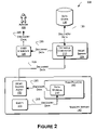
- FIG. 2 is a block diagram illustrating various components and data flows associated with receiving and processing discovery data resulting from discovering the entity shown in FIG. 1 .
- FIG. 3 is a diagram of a user interface that provides a state view of the discovery data.
- FIG. 4 is a diagram of a user interface that provides a computer view of the discovery data.
- FIG. 5 is a diagram of user interface that provides a diagram or topological view of the discovery data.
- FIG. 6 illustrates a computing environment within which systems and methods for efficient processing of time-bounded messages, as well as the computing, network, and system architectures described herein, can be either fully or partially implemented.
- An overall process performed by the teachings herein can include enabling definition of one or more rules for discovering data about at least one entity related to, for example, a computer-based server. This aspect of the overall process is shown in more detail in FIG. 1 , which illustrates an implementation in the context of an operations management system.
- the overall process also can include receiving discovery data in response to the rules being executed in an environment in which the entity is deployed.
- This aspect of the overall process is shown in more detail in FIG. 2 , which illustrates an implementation in the context of performing data discovery in an operations management system.
- FIG. 1 illustrates a management system 100 featuring various components and data flows associated with performing service discovery.
- An author 105 drafts one or more discovery rules 110 that are designed to discover information about one or more services or entities 115 that are managed within the management system 100 .
- a suitable example of the management system 100 is the Microsoft Operations Manager (MOM) system, available from Microsoft Corporation. Further background on the MOM system is readily available from the Microsoft website.
- MOM Microsoft Operations Manager
- such a management system 100 enables the author 105 to specify rules 110 that can perform a variety of management-related functions within the management system 100 .
- these rules 110 are the discovery rules 110 discussed herein.
- These discovery rules 110 can be collected from the author 105 via a user interface 120 , and forwarded to a management server 125 .
- the management server 125 can embody these discovery rules 110 into discovery scripts to be run later, and can load these discovery rules and related scripts into management packs (MPs) 130 .
- the management server 125 can store the MPs 130 into a data store 135 for later retrieval.
- the management server 125 is generally responsible for coordinating the management of remote entities, such as managed servers 140 .
- managed servers 140 One managed server 140 is shown in FIG. 1 for clarity and conciseness, but not limitation.
- the MPs 130 are made available for download by or to the managed servers 140 , and thus new MPs 130 are imported by the managed servers 140 , as indicated by the line 145 .
- the transmission of MPs 130 to the managed servers 140 can be implemented as either a push or pull model, or any combination of the foregoing.
- a management system agent 150 on the managed server 140 receives the MPs 130 , and extracts therefrom the discovery script 155 embodying the discovery rules 110 drafted by the author 105 .
- the management system agent 150 then forwards the discovery script 155 to a host process 160 .
- the host process 160 may be spawned specifically for executing the discovery script 155 , or may be standing-by, having already been created.
- the discovery script 155 can be stored in a script storage structure 165 for convenience.
- the script storage structure 165 can take the form of a buffer, cache, or other form of relatively temporary memory location, and be implemented in connection with any suitable data structure.
- the discovery script 155 can be defined to execute at any interval deemed appropriate by the author 105 , for example, hourly, daily, weekly, or the like. At the interval specified in the discovery script 155 , it is executed on the managed server 140 by the host process 160 to discover one or more entities 115 .
- the discovery script 155 can be configured to discover information about any entity 115 within the domain of a given managed server 140 . Examples of the entities 115 that can be discovered include any physical or logical device, any service, or any other component on the managed server 140 .
- the different entities 115 that may be discovered on the managed servers 140 may be grouped into classes, with the discovery rules 110 locating specific instances of each class existing on a given managed server 140 .
- the discovery rules 110 can also define the properties of each instance of a given class, and define the relationships among classes or instances of classes.
- the discovery script 155 may utilize services such as the ACTIVE DIRECTORYTM service available from Microsoft, may refer to a system registry or other equivalent file structure indicating how the managed server 140 is configured, or the like.
- the flexibility offered by the rule generation and execution process described above can enable customers using the management system 100 to evolve beyond managing their enterprises at a computer-by-computer level.
- Customers may not wish to manage each computer or other such entity in their enterprise on this type of a piecemeal basis, but instead may wish to manage on a “service” level, or a “group of services” level.
- the management approaches progresses beyond managing a set of physical devices toward managing a set of services or logical entities within the enterprise.
- a given enterprise includes a messaging and collaboration service such as the EXCHANGE SERVERTM service offered by Microsoft
- the customer may not be as concerned with how many computers implement the service, or with the status of each computer, but instead may be more concerned with logical groups within the deployment of EXCHANGE SERVER, such as a group of servers designated as a “routing group”.
- Other examples of entities 115 can include logical or physical disk drives, lists of SQL instances, and attributes of respective computers, such the version of the operating system they are running, a language identifier, or the like.
- FIG. 2 illustrates components and data flows 200 associated with the management system 100 when reporting discovery data after execution of the discovery script 155 .
- the discovery script 155 executes on the given managed server 140 , it locates and gathers data about entities 115 in response to the discovery rules 110 .
- This data is referred to generally herein as discovery data 205 .
- the host process 160 can store it for convenience in a data storage structure 210 , which may be implemented similarly to the script storage structure 165 discussed above in connection with FIG. 1 .
- the host process 160 can forward the discovery data 205 to the management system agent 150 .
- the discovery data 205 pertaining to the entity 115 can be reported back alone, or can be combined with discovery data 205 pertaining to other entities 115 within the managed server 140 .
- the discovery data 205 can be reported immediately upon discovery, or can be collected for some time before reporting, as may be appropriate in particular applications.
- the processing for the discovery data 205 can be similar to processing other data items such as alerts, events, and other types of performance-related data in scripts.
- the discovery data 205 can be reported to the management server 125 , more particularly, to a database connector component 215 .
- the database connector component 215 functions to organize the discovery data 205 , and can further function to provide state context for various instances of the discovery data 205 as received by the management server 125 .
- the discovery script 155 as executed at the level of a given managed server 140 at a given time is stateless, in that it does not maintain any memory or history of what it may have found on the given managed server 140 before.
- the discovery script 155 executes to find three instances of a SQL server on the given managed server 140 . Assume that later, at a time t 1 , the discovery script 155 executes to find only two instances. In this embodiment, the discovery script 155 at time t 1 does not know what was found previously at t o , because of its stateless nature. However, the database connector component 215 can maintain state context of what discovery data 205 resulted from various executions of the discovery script 155 at respective items.
- the database connector component 215 can analyze various instances of a history of the discovery data 205 , and can determine that one less instance of the SQL server exists at time t 1 as compared to what existed previously at time t 0 . Therefore, the database connector component 215 can provide state context at the level of the management server 125 that may be missing at the level of the managed servers 140 .
- the managed servers 140 can be made more state-aware, such that they only report discovery data 205 back to the management server 125 when a given execution of the discovery script 155 results in discovery data 205 that is different from previous discovery data 205 .
- the discovery data 205 is reported to the management server 125 only when the discovery data 205 changes.
- This alternative embodiment can reduce the volume of message flow between the managed servers 140 and the management server 125 .
- the database connector component 215 can also validate the discovery data 205 as reported by the various management system agents 150 .
- a given discovery script 155 may locate an instances of a given class “X” on a given managed server 140 , and report this instance as part of the discovery data 205 .
- the database connector component 215 can validate all classes included in the discovery data 205 by comparing them to, for example, a schema listing all valid classes. This schema may be stored in the data store 135 , for example. If the given class “X” as reported in the discovery data 205 is invalid, the database connector component 215 can detect this condition as part of its analysis, and report this condition accordingly.
- the database connector component 215 loads it into the data store 135 . Assuming the data store 135 is implemented as a database, tables within this database can be populated with the discovery data 205 .
- the script can call a method to submit the discovery data 205 to the management server 125 , as follows: ScriptContext.Submit(objDiscData)
- the following describes the object DiscoveryData, which is returned by the CreateDiscoveryData, and also describes other objects used by the DiscoveryData object.
- the discovery data object has the following properties and methods:
- the discovery collection object contains the instances discovered for a specific Class and for a specific scope.
- a discovery collection object can contain a list of all SQL instances on a given machine “SERVER01”.
- This object can represent the properties collected for an instance.
- a collection object contains a list of instances, while each instance is represented with this object.
- the user interface 120 can take several different forms in various implementations of the teachings herein, and can present the discovery data 205 received from the various managed servers 140 in a variety of ways.
- the data presented by these various forms of the user interface 120 are based on discovery data 205 as can be stored in the data store 135 .
- FIG. 3 illustrates an implementation of the user interface 120 that provides a state view 300 of the discovery data 205 .
- the state view 300 can be activated by, for example, clicking on the field 305 labeled “State”.
- column 315 lists several computers discovered on various managed servers 140 , along with a name for each computer. These names may be discovered from the computer itself, or the names may be pulled from an entry provided by a service such as ACTIVE DIRECTORY.
- the illustrative roles 320 are examples of classes that might be defined by MPs 130 and referenced by the discovery rules 110 . These classes are discovered by the discovery scripts 155 as they are executed on the various managed servers 140 .
- each cell within this grid can contain an icon 325 indicating the state of each given role 320 on each given computer 315 .
- the meaning of each of the illustrative icons 325 is given in the legend shown in FIG. 5 .
- the state of a given role 320 on a given computer 315 can be shown in more detail, for example, by clicking on a cell 330 , which represents the intersection of the role “SQL” with the computer “CPICK01E”.
- the state view 300 presents additional data in a field 335 .
- the contents of this field 335 are indicated by the banner 340 , which indicates the computer “CPICK01E” and the role “SQL”.
- a set of properties are shown for the SQL role or class, along with corresponding icons representing the state of each property.
- a column 350 lists a name for each instance of the role 320 as it appears on the computer 315 , and an icon 355 indicates an overall status of each instance 350 .
- FIG. 4 illustrates an implementation of the user interface 120 that provides a computer view 400 of the discovery data 205 .
- the computer view 400 can be activated by, for example, by clicking on the field 405 labeled “Computers and Groups”.
- An area 410 lists the names and several parameters relating to computers, the names of which are listed in a column 415 . Each computer is listed in a respective row 420 .
- Additional information on a given computer 415 can be obtained by clicking on the row 420 corresponding to that computer 420 . Assuming that a user clicks on the row 420 , area 425 is populated with further details pertaining to the computer named “BRETTE03E”. A series of tabs 430 organize this information for convenience within area 425 . By clicking on the tab labeled “Roles”, the user can receive a list of roles in area 425 . Items 435 represent particular classes of entities 115 found on the managed server 140 corresponding to the row 420 that was clicked to present the data shown in area 425 . Items 440 represent respective instances of each class 435 . For each instance 440 of a class 435 , a set of properties 445 is presented. For example, table 450 presents the respective properties of three instances of the class “disk” found on the computer “BRETTE03E” by the discovery script 155 .
- FIG. 5 illustrates an implementation of the user interface 120 that provides a diagram or topological view 500 of the discovery data 205 .
- the diagram view 500 can be activated by, for example, clicking on a field 505 .
- the diagram view 500 includes an area 510 that presents icons 515 representing the various managed servers 140 within the management system 100 , along with an icon 520 representing the management server 125 .
- the diagram view 500 also associates a further respective icon 525 with each of the icons 515 and 520 , to indicate the state or status of the entities represented by the icons 515 and 520 .
- the diagram view 500 can also include a legend 530 that can be displayed on command to explain the meaning of each of the icons 515 , 520 , and 525 .
- FIG. 6 illustrates a computing environment 600 for efficiently processing time-bounded messages, and for fully or partially implementing the computing, network, and system architectures described herein. More particularly, the computing environment 600 may be suitable for implementing and/or supporting various components described herein, including but not limited to aspects of the user interface 120 , the management server 125 , the managed servers 140 , the database connector component 215 , the host process 160 , and the like.
- Exemplary computing environment 600 is only one example of a computing system and is not intended to suggest any limitation as to the scope of use or functionality of the architectures. Neither should the computing environment 600 be interpreted as having any dependency or requirement relating to any one or combination of components illustrated in the exemplary computing environment 600 .
- the computer and network architectures in computing environment 600 can be implemented with numerous other general purpose or special purpose computing system environments or configurations.
- Examples of well known computing systems, environments, and/or configurations that may be suitable for use include, but are not limited to, personal computers, server computers, client devices, hand-held or laptop devices, microprocessor-based systems, multiprocessor systems, set top boxes, programmable consumer electronics, network PCs, minicomputers, mainframe computers, gaming consoles, distributed computing environments that include any of the above systems or devices, and the like.
- the computing environment 600 includes a general-purpose computing system in the form of a computing device 602 .
- the components of computing device 602 can include, but are not limited to, one or more processors 604 (e.g., any of microprocessors, controllers, and the like), a system memory 606 , and a system bus 608 that couples the various system components.
- the one or more processors 604 process various computer executable instructions to control the operation of computing device 602 and to communicate with other electronic and computing devices.
- the system bus 608 represents any number of several types of bus structures, including a memory bus or memory controller, a peripheral bus, an accelerated graphics port, and a processor or local bus using any of a variety of bus architectures.
- Computing environment 600 includes a variety of computer readable media which can be any media that is accessible by computing device 602 and includes both volatile and non-volatile media, removable and non-removable media.
- the system memory 606 includes computer readable media in the form of volatile memory, such as random access memory (RAM) 610 , and/or non-volatile memory, such as read only memory (ROM) 612 .
- RAM 610 typically contains data and/or program modules that are immediately accessible to and/or presently operated on by one or more of the processors 604 .
- Computing device 602 may include other removable/non-removable, volatile/non-volatile computer storage media.
- a hard disk drive 616 reads from and writes to a non-removable, non-volatile magnetic media (not shown)
- a magnetic disk drive 618 reads from and writes to a removable, non-volatile magnetic disk 620 (e.g., a “floppy disk”)
- an optical disk drive 622 reads from and/or writes to a removable, non-volatile optical disk 624 such as a CD-ROM, digital versatile disk (DVD), or any other type of optical media.
- DVD digital versatile disk
- the hard disk drive 616 , magnetic disk drive 618 , and optical disk drive 622 are each connected to the system bus 608 by one or more data media interfaces 626 .
- the disk drives and associated computer readable media provide non-volatile storage of computer readable instructions, data structures, program modules, and other data for computing device 602 .
- Any number of program modules can be stored on RAM 610 , ROM 612 , hard disk 616 , magnetic disk 620 , and/or optical disk 624 , including by way of example, an operating system 628 , one or more application programs 630 , other program modules 632 , and program data 634 .
- an operating system 628 one or more application programs 630 , other program modules 632 , and program data 634 .
- Each of such operating system 628 , application program(s) 630 , other program modules 632 , program data 634 , or any combination thereof, may include one or more embodiments of the systems and methods described herein.
- Computing device 602 can include a variety of computer readable media identified as communication media.
- Communication media typically embodies computer readable instructions, data structures, program modules, or other data in a modulated data signal such as a carrier wave or other transport mechanism and includes any information delivery media.
- modulated data signal refers to a signal that has one or more of its characteristics set or changed in such a manner as to encode information in the signal.
- communication media includes wired media such as a wired network or direct-wired connection, and wireless media such as acoustic, RF, infrared, other wireless media, and/or any combination thereof.
- a user can interface with computing device 602 via any number of different input devices such as a keyboard 636 and pointing device 638 (e.g., a “mouse”). Also, the user can use a mobile phone as a client to practice the teachings herein. More particularly, the user interface 120 as shown in FIGS. 1-5 may be adapted as appropriate to be supported by a mobile phone used by the author 105 .
- Other input devices 640 may include a microphone, joystick, game pad, controller, satellite dish, serial port, scanner, and/or the like.
- processors 604 are connected to the processors 604 via input/output interfaces 642 that are coupled to the system bus 608 , but may be connected by other interface and bus structures, such as a parallel port, game port, and/or a universal serial bus (USB).
- input/output interfaces 642 that are coupled to the system bus 608 , but may be connected by other interface and bus structures, such as a parallel port, game port, and/or a universal serial bus (USB).
- USB universal serial bus
- a display device 644 (or other type of monitor) can be connected to the system bus 608 via an interface, such as a video adapter 646 .
- other output peripheral devices can include components such as speakers (not shown) and a printer 648 which can be connected to computing device 602 via the input/output interfaces 642 .
- Computing device 602 can operate in a networked environment using logical connections to one or more remote computers, such as remote computing device 650 .
- remote computing device 650 can be a personal computer, portable computer, a server, a router, a network computer, a peer device or other common network node, and the like.
- the remote computing device 650 is illustrated as a portable computer that can include any number and combination of the different components, elements, and features described herein relative to computing device 602 .
- Logical connections between computing device 602 and the remote computing device 650 are depicted as a local area network (LAN) 652 and a general wide area network (WAN) 654 .
- LAN local area network
- WAN wide area network
- Such networking environments are commonplace in offices, enterprise-wide computer networks, intranets, and the Internet.
- the computing device 602 When implemented in a LAN networking environment, the computing device 602 is connected to a local network 652 via a network interface or adapter 656 .
- the computing device 602 When implemented in a WAN networking environment, the computing device 602 typically includes a modem 658 or other means for establishing communications over the wide area network 654 .
- the modem 658 can be internal or external to computing device 602 , and can be connected to the system bus 608 via the input/output interfaces 642 or other appropriate mechanisms.
- the illustrated network connections are merely exemplary and other means of establishing communication link(s) between the computing devices 602 and 650 can be utilized.
- program modules depicted relative to the computing device 602 may be stored in a remote memory storage device.
- remote application programs 660 are maintained with a memory device of remote computing device 650 .
- application programs and other executable program components, such as operating system 628 are illustrated herein as discrete blocks, although it is recognized that such programs and components reside at various times in different storage components of the computing device 602 , and are executed by the one or more processors 604 of the computing device 602 .
Abstract
Description
| - <DataItem TYPEID=“79cbb19c-a897-440f-8e99-28c2649745ac”> | |
| <InstanceID>{E5BC859E-E3F5-4C1D-8D76-1A5316E39ACF}</ | |
| InstanceID> | |
| <ProviderID>{F320DA51-13BF-18D3-B3CD-00A0C53A28B4}</ | |
| ProviderID> | |
| <ProviderName>MOM provider name</ProviderName> | |
| <Time TimeString=“11/18/2004 01:51:16”>38309.0772746759</Time> | |
| <Computer>DEVW2K3STD3</Computer> | |
| <RuleID>{89184DE1-6B0D-4D5D-8764-611F8E18552D}</RuleID> | |
| <ScopeID>{86C03298-37D5-4587-A40F-6BA618D9AC3E}</ | |
| ScopeID> | |
| - <Collections> | |
| - <Collection> | |
| <ClassName>Class name</ClassName> | |
| - <Scope> | |
| - <Property> | |
| <Name>Property 1</Name> | |
| <Key Type=“Boolean”>1</Key> | |
| </Property> | |
| - <Property> | |
| <Name>Property 2</Name> | |
| <Key Type=“Boolean”>0</Key> | |
| </Property> | |
| </Scope> | |
| - <Instances> | |
| - <Instance> | |
| - <Property> | |
| <Name>Property 1</Name> | |
| <Value>Keyname</Value> | |
| <Key Type=“Boolean”>1</Key> | |
| </Property> | |
| - <Property> | |
| <Name>Property 2</Name> | |
| <Value>value for property 2</Value> | |
| <Key Type=“Boolean”>0</Key> | |
| </Property> | |
| </Instance> | |
| </Instances> | |
| </Collection> | |
| </Collections> | |
| </DataItem> | |
objDiscData=ScriptContext.CreateDiscoveryData
ScriptContext.Submit(objDiscData)
-
- Method CreateCollection( ): DiscoveryCollection
- This method Creates an empty DiscoveryCollection object and returns it.
- Method AddCollection(DiscoveryCollection obj)
- Adds a collection object to the
discovery data 205. A single instance of thediscovery data 205 may contain multiple collection objects.
- Adds a collection object to the
- Property CollectionCount: Integer
- Supports “Get” method. Returns the collection count of the current discovery data object.
DiscoveryCollection Object
- Supports “Get” method. Returns the collection count of the current discovery data object.
- Method CreateCollection( ): DiscoveryCollection
-
- Property ClassID:String
- Supports “Get” and “Set”. ClassID identifies the target class of which the collection contains instances. ClassID can be either a name that identifies the class, such as “SQLInstance”, or a GUID such as “{5C46EDA4-AA2B-11D2-86B0-00A0C9AFE085}”.
- Method AddScopeFilter(String KeyPropertyId, String Value)
- Adds a scope filter to the collection. A scope filter identifies the target set of instances that this collection is to contain. For example, if the collection contains a list of SQL Instances on Machine SERVER01, the scope can be defined by calling:
- objCollection.AddScopeFilter(“MachineName”,“SERVER01”)
- If the collection contains information about a specific SQL Instance, such as SQL1, then the following scope filter can be added as well:
- obj Collection.AddScopeFilter(“SQLInstanceName”,“S QL1”)
- The KeyPropertyID parameter can be either a name of a property or a GUID of the property.
- Adds a scope filter to the collection. A scope filter identifies the target set of instances that this collection is to contain. For example, if the collection contains a list of SQL Instances on Machine SERVER01, the scope can be defined by calling:
- Method AddScopeProperty(String PropertyId)
- Adds a property to the property list that identifies the properties of the Class that this collection has discovered. For example, if the collection contains a list of SQL Instances on machine “SERVER01”, where each instance also contains the DBCount property, then this method can be called as follows:
- Method AddScopeProperty(“DBCount”)
- The parameter PropertyID can be either the name of the property or the GUID.
- Adds a property to the property list that identifies the properties of the Class that this collection has discovered. For example, if the collection contains a list of SQL Instances on machine “SERVER01”, where each instance also contains the DBCount property, then this method can be called as follows:
- Property ScopeFilters:String
- Supports “GET”. Returns a list of current scope filters in the collection as a string.
- Property ScopeProperties:String
- Supports “GET”. Returns a list of properties that this collection contains.
- Method CreateInstance( ):DiscoveryInstance
- Creates a DiscoveryInstance object and returns it.
- Method AddInstance(DiscoveryInstance obj)
- Adds a DiscoveryInstance object to the collection.
- Property InstanceCount:Integer
- Returns the number of instances in the collection object.
DiscoveryInstance Object
- Returns the number of instances in the collection object.
- Property ClassID:String
-
- Method AddProperty(String PropertyID, String Value)
- This method adds a property, value pair to the instance data. The PropertyID can be either a name or a GUID. The property specified here is added to the collection as a Scope Property, and can be a non-key property of the class. For example this method can be called as follows:
- objInstance.AddProperty(“DBCount”,“12”)
- This method adds a property, value pair to the instance data. The PropertyID can be either a name or a GUID. The property specified here is added to the collection as a Scope Property, and can be a non-key property of the class. For example this method can be called as follows:
- Method AddKeyProperty(String KeyPropertyID, String Value)
- This method adds a key property value to the instance object, in which the key property is used to identify the instance in question. Example usage for this method is as follows:
- objInstance.AddKeyProperty(“SQLInstanceName”,“S QL”)
- This method adds a key property value to the instance object, in which the key property is used to identify the instance in question. Example usage for this method is as follows:
- Property InstanceInfo: String
- Supports “GET”. Returns a string which summarizes the contents of the instance object.
- Method AddProperty(String PropertyID, String Value)
| // |
| // scenario: discover the list of SQL Instances on machine SERVER01 |
| // including the DBCount Property |
| // |
| Dim objDiscData // discovery data |
| Dim objSQLInstCollection // disc data for SQL Instance on SERVER01 |
| Dim objInstance // discovery data for one SQL Instance |
| // create the discovery event |
| objDiscData = ScriptContext.CreateDiscoveryData |
| // create collection for the result for SQL Instances on SERVER01 |
| objSQLInstCollection = objDiscData.CreateCollection |
| // specify that Collection is for SQLInstance Class |
| objSQLInstCollection.ClassID = “SQLInstance” |
| // specify that collection contains results for only on machine SERVER01 |
| objSQLInstCollection.AddScopeFilter(“MachineName”,“SERVER01”) |
| // specify that collection will also contain the DBCount property of |
| // the SQL Instance |
| objSQLInstCollection.AddScopeProperty(“DBCount”) |
| // |
| // after some queries, assume script has discovered the SQL Instances |
| // SERVER01\SQL1 with DBCount=10, SERVER01\SQL2 with |
| DBCount=3 |
| // |
| // create the instance that will contain info for SERVER01\SQL1 |
| objInstance = objSQLInstCollection.CreateInstance |
| // |
| // specify the SQLInstance Name which identifies the instance of |
| // SQLInst class |
| objInstance.AddKeyProperty(“SQLInstanceName”,“SQL1”) |
| // specify the DBCount property |
| objInstance.AddProperty(“DBCount”,“10”) |
| // add the Instance to the collection |
| objSQLInstCollection.AddInstance(objInstance) |
| // |
| // add the instance FERITF/SQL2 to the collection as well |
| objInstance = objSQLInstCollection.CreateInstance |
| objInstance.AddKeyProperty(“SQLInstanceName”,“SQL2”) |
| objInstance.AddProperty(“DBCount”,“3”) |
| objSQLInstCollection.AddInstance(objInstance) |
| // |
| // add the collection to the discovery data |
| objDiscData.AddCollection(objSQLInstCollection) |
| // |
| // discovery data is ready to be sent, send it |
| ScriptContext.Submit(objDiscData) |
| // DONE... |
Claims (12)
Priority Applications (1)
| Application Number | Priority Date | Filing Date | Title |
|---|---|---|---|
| US11/142,573 US7720950B2 (en) | 2005-06-01 | 2005-06-01 | Discovery, maintenance, and representation of entities in a managed system environment |
Applications Claiming Priority (1)
| Application Number | Priority Date | Filing Date | Title |
|---|---|---|---|
| US11/142,573 US7720950B2 (en) | 2005-06-01 | 2005-06-01 | Discovery, maintenance, and representation of entities in a managed system environment |
Publications (2)
| Publication Number | Publication Date |
|---|---|
| US20070005544A1 US20070005544A1 (en) | 2007-01-04 |
| US7720950B2 true US7720950B2 (en) | 2010-05-18 |
Family
ID=37590915
Family Applications (1)
| Application Number | Title | Priority Date | Filing Date |
|---|---|---|---|
| US11/142,573 Active 2027-12-07 US7720950B2 (en) | 2005-06-01 | 2005-06-01 | Discovery, maintenance, and representation of entities in a managed system environment |
Country Status (1)
| Country | Link |
|---|---|
| US (1) | US7720950B2 (en) |
Cited By (7)
| Publication number | Priority date | Publication date | Assignee | Title |
|---|---|---|---|---|
| US20080071727A1 (en) * | 2006-09-18 | 2008-03-20 | Emc Corporation | Environment classification |
| US20160379196A1 (en) * | 2015-06-26 | 2016-12-29 | Seiko Epson Corporation | Network System, Control Method of a Network System, and Management Server |
| WO2018191294A1 (en) * | 2017-04-10 | 2018-10-18 | Bdna Corporation | Classification of objects |
| US10313200B2 (en) | 2017-09-15 | 2019-06-04 | Bdna Corporation | Unix file and process mapping |
| US10586209B2 (en) | 2002-04-18 | 2020-03-10 | Bdna Corporation | Automatically collecting data regarding assets of a business entity |
| US10977754B2 (en) | 2004-12-13 | 2021-04-13 | Bdna Corporation | System for linking financial asset records with networked assets |
| US11863619B1 (en) | 2023-01-17 | 2024-01-02 | Micro Focus Llc | Computing resources discovery via replacing filter parameter of input query with discovery job parameter |
Families Citing this family (4)
| Publication number | Priority date | Publication date | Assignee | Title |
|---|---|---|---|---|
| US9319246B2 (en) | 2012-06-25 | 2016-04-19 | Microsoft Technology Licensing, Llc | Voice-over-internet protocol (VOIP) application platform |
| US9191417B2 (en) | 2012-06-28 | 2015-11-17 | Microsoft Technology Licensing, Llc | Cross-process media handling in a voice-over-internet protocol (VOIP) application platform |
| US10511694B2 (en) * | 2014-07-23 | 2019-12-17 | Citrix Systems, Inc. | Systems and methods for application specific load balancing |
| US9998341B2 (en) * | 2015-01-09 | 2018-06-12 | Lg Cns Co., Ltd. | Method of constructing data collector, server performing the same and storage medium for the same |
Citations (30)
| Publication number | Priority date | Publication date | Assignee | Title |
|---|---|---|---|---|
| US5491796A (en) * | 1992-10-23 | 1996-02-13 | Net Labs, Inc. | Apparatus for remotely managing diverse information network resources |
| US5655081A (en) * | 1995-03-08 | 1997-08-05 | Bmc Software, Inc. | System for monitoring and managing computer resources and applications across a distributed computing environment using an intelligent autonomous agent architecture |
| US6041347A (en) * | 1997-10-24 | 2000-03-21 | Unified Access Communications | Computer system and computer-implemented process for simultaneous configuration and monitoring of a computer network |
| US6154776A (en) * | 1998-03-20 | 2000-11-28 | Sun Microsystems, Inc. | Quality of service allocation on a network |
| US6167448A (en) * | 1998-06-11 | 2000-12-26 | Compaq Computer Corporation | Management event notification system using event notification messages written using a markup language |
| US6229540B1 (en) * | 1996-02-23 | 2001-05-08 | Visionael Corporation | Auditing networks |
| US6230200B1 (en) * | 1997-09-08 | 2001-05-08 | Emc Corporation | Dynamic modeling for resource allocation in a file server |
| US6308206B1 (en) * | 1997-09-17 | 2001-10-23 | Hewlett-Packard Company | Internet enabled computer system management |
| US6401119B1 (en) | 1998-09-18 | 2002-06-04 | Ics Intellegent Communication Software Gmbh | Method and system for monitoring and managing network condition |
| US20020085571A1 (en) | 1997-11-04 | 2002-07-04 | Branislav N. Meandzija | Enhanced simple network management protocol (snmp) for network and systems management |
| US6490617B1 (en) * | 1998-06-09 | 2002-12-03 | Compaq Information Technologies Group, L.P. | Active self discovery of devices that participate in a network |
| US6535868B1 (en) * | 1998-08-27 | 2003-03-18 | Debra A. Galeazzi | Method and apparatus for managing metadata in a database management system |
| US6539427B1 (en) * | 1999-06-29 | 2003-03-25 | Cisco Technology, Inc. | Dynamically adaptive network element in a feedback-based data network |
| US6549943B1 (en) * | 1999-06-16 | 2003-04-15 | Cisco Technology, Inc. | Network management using abstract device descriptions |
| US6567814B1 (en) * | 1998-08-26 | 2003-05-20 | Thinkanalytics Ltd | Method and apparatus for knowledge discovery in databases |
| US6584502B1 (en) * | 1999-06-29 | 2003-06-24 | Cisco Technology, Inc. | Technique for providing automatic event notification of changing network conditions to network elements in an adaptive, feedback-based data network |
| WO2003053061A1 (en) | 2001-12-18 | 2003-06-26 | Igys Systems, Inc. | Facility monitoring control systems and methods |
| US6625648B1 (en) * | 2000-01-07 | 2003-09-23 | Netiq Corporation | Methods, systems and computer program products for network performance testing through active endpoint pair based testing and passive application monitoring |
| US20030200304A1 (en) * | 2002-04-18 | 2003-10-23 | Thorpe John Robert | Apparatus and method to automatically collect data regarding assets of a business entity |
| US6664978B1 (en) | 1997-11-17 | 2003-12-16 | Fujitsu Limited | Client-server computer network management architecture |
| US6748436B1 (en) | 2000-05-04 | 2004-06-08 | International Business Machines Corporation | System, method and program for management of users, groups, servers and resources in a heterogeneous network environment |
| WO2004081827A1 (en) | 2003-03-12 | 2004-09-23 | Intotality Pty Ltd | Automated application discovery and analysis system and method |
| US20040249919A1 (en) | 2003-06-04 | 2004-12-09 | Dirk Mattheis | System and method for remote systems management and reporting |
| US6834298B1 (en) * | 1999-09-21 | 2004-12-21 | Siemens Information And Communication Networks, Inc. | System and method for network auto-discovery and configuration |
| US6988134B2 (en) * | 2002-04-18 | 2006-01-17 | Bdna Corporation | Apparatus and method to automatically collect data regarding assets of a business entity |
| US7107273B2 (en) * | 2003-11-28 | 2006-09-12 | Hitachi, Ltd. | Method and program of collecting performance data for storage network |
| US7139764B2 (en) * | 2003-06-25 | 2006-11-21 | Lee Shih-Jong J | Dynamic learning and knowledge representation for data mining |
| US7155502B1 (en) * | 2002-06-17 | 2006-12-26 | Packeteer, Inc. | Methods, apparatuses and systems facilitating distribution of updated traffic identification functionality to bandwidth management devices |
| US7433943B1 (en) * | 2001-12-20 | 2008-10-07 | Packeteer, Inc. | Volume-based network management scheme |
| US7493388B2 (en) * | 2004-08-20 | 2009-02-17 | Bdna Corporation | Method and/or system for identifying information appliances |
-
2005
- 2005-06-01 US US11/142,573 patent/US7720950B2/en active Active
Patent Citations (31)
| Publication number | Priority date | Publication date | Assignee | Title |
|---|---|---|---|---|
| US5491796A (en) * | 1992-10-23 | 1996-02-13 | Net Labs, Inc. | Apparatus for remotely managing diverse information network resources |
| US5655081A (en) * | 1995-03-08 | 1997-08-05 | Bmc Software, Inc. | System for monitoring and managing computer resources and applications across a distributed computing environment using an intelligent autonomous agent architecture |
| US6229540B1 (en) * | 1996-02-23 | 2001-05-08 | Visionael Corporation | Auditing networks |
| US6230200B1 (en) * | 1997-09-08 | 2001-05-08 | Emc Corporation | Dynamic modeling for resource allocation in a file server |
| US6308206B1 (en) * | 1997-09-17 | 2001-10-23 | Hewlett-Packard Company | Internet enabled computer system management |
| US6041347A (en) * | 1997-10-24 | 2000-03-21 | Unified Access Communications | Computer system and computer-implemented process for simultaneous configuration and monitoring of a computer network |
| US20020085571A1 (en) | 1997-11-04 | 2002-07-04 | Branislav N. Meandzija | Enhanced simple network management protocol (snmp) for network and systems management |
| US6664978B1 (en) | 1997-11-17 | 2003-12-16 | Fujitsu Limited | Client-server computer network management architecture |
| US6154776A (en) * | 1998-03-20 | 2000-11-28 | Sun Microsystems, Inc. | Quality of service allocation on a network |
| US6490617B1 (en) * | 1998-06-09 | 2002-12-03 | Compaq Information Technologies Group, L.P. | Active self discovery of devices that participate in a network |
| US6167448A (en) * | 1998-06-11 | 2000-12-26 | Compaq Computer Corporation | Management event notification system using event notification messages written using a markup language |
| US6567814B1 (en) * | 1998-08-26 | 2003-05-20 | Thinkanalytics Ltd | Method and apparatus for knowledge discovery in databases |
| US6535868B1 (en) * | 1998-08-27 | 2003-03-18 | Debra A. Galeazzi | Method and apparatus for managing metadata in a database management system |
| US6401119B1 (en) | 1998-09-18 | 2002-06-04 | Ics Intellegent Communication Software Gmbh | Method and system for monitoring and managing network condition |
| US6549943B1 (en) * | 1999-06-16 | 2003-04-15 | Cisco Technology, Inc. | Network management using abstract device descriptions |
| US6754703B1 (en) * | 1999-06-16 | 2004-06-22 | Cisco Technology Inc. | Network management using abstract device descriptions |
| US6539427B1 (en) * | 1999-06-29 | 2003-03-25 | Cisco Technology, Inc. | Dynamically adaptive network element in a feedback-based data network |
| US6584502B1 (en) * | 1999-06-29 | 2003-06-24 | Cisco Technology, Inc. | Technique for providing automatic event notification of changing network conditions to network elements in an adaptive, feedback-based data network |
| US6834298B1 (en) * | 1999-09-21 | 2004-12-21 | Siemens Information And Communication Networks, Inc. | System and method for network auto-discovery and configuration |
| US6625648B1 (en) * | 2000-01-07 | 2003-09-23 | Netiq Corporation | Methods, systems and computer program products for network performance testing through active endpoint pair based testing and passive application monitoring |
| US6748436B1 (en) | 2000-05-04 | 2004-06-08 | International Business Machines Corporation | System, method and program for management of users, groups, servers and resources in a heterogeneous network environment |
| WO2003053061A1 (en) | 2001-12-18 | 2003-06-26 | Igys Systems, Inc. | Facility monitoring control systems and methods |
| US7433943B1 (en) * | 2001-12-20 | 2008-10-07 | Packeteer, Inc. | Volume-based network management scheme |
| US20030200304A1 (en) * | 2002-04-18 | 2003-10-23 | Thorpe John Robert | Apparatus and method to automatically collect data regarding assets of a business entity |
| US6988134B2 (en) * | 2002-04-18 | 2006-01-17 | Bdna Corporation | Apparatus and method to automatically collect data regarding assets of a business entity |
| US7155502B1 (en) * | 2002-06-17 | 2006-12-26 | Packeteer, Inc. | Methods, apparatuses and systems facilitating distribution of updated traffic identification functionality to bandwidth management devices |
| WO2004081827A1 (en) | 2003-03-12 | 2004-09-23 | Intotality Pty Ltd | Automated application discovery and analysis system and method |
| US20040249919A1 (en) | 2003-06-04 | 2004-12-09 | Dirk Mattheis | System and method for remote systems management and reporting |
| US7139764B2 (en) * | 2003-06-25 | 2006-11-21 | Lee Shih-Jong J | Dynamic learning and knowledge representation for data mining |
| US7107273B2 (en) * | 2003-11-28 | 2006-09-12 | Hitachi, Ltd. | Method and program of collecting performance data for storage network |
| US7493388B2 (en) * | 2004-08-20 | 2009-02-17 | Bdna Corporation | Method and/or system for identifying information appliances |
Non-Patent Citations (3)
| Title |
|---|
| "Efficient Administration of Homogeneous and Heterogeneous Computer Networks"; SC Venus, 4 pages. |
| http://www3.ca.com/solutions/product.asp?id=2869. |
| IBM Think Research/Servers & Systems Management; http;//www.research.ibm.com/thinkresearch/systems.shtml; 1 page. |
Cited By (12)
| Publication number | Priority date | Publication date | Assignee | Title |
|---|---|---|---|---|
| US10586209B2 (en) | 2002-04-18 | 2020-03-10 | Bdna Corporation | Automatically collecting data regarding assets of a business entity |
| US10977754B2 (en) | 2004-12-13 | 2021-04-13 | Bdna Corporation | System for linking financial asset records with networked assets |
| US11069014B2 (en) | 2004-12-13 | 2021-07-20 | Bdna Corporation | System for linking financial asset records with networked assets |
| US20080071727A1 (en) * | 2006-09-18 | 2008-03-20 | Emc Corporation | Environment classification |
| US9135322B2 (en) * | 2006-09-18 | 2015-09-15 | Emc Corporation | Environment classification |
| US11846978B2 (en) | 2006-09-18 | 2023-12-19 | EMC IP Holding Company LLC | Cascaded discovery of information environment |
| US20160379196A1 (en) * | 2015-06-26 | 2016-12-29 | Seiko Epson Corporation | Network System, Control Method of a Network System, and Management Server |
| US10229403B2 (en) * | 2015-06-26 | 2019-03-12 | Seiko Epson Corporation | Network system, control method of a network system, and management server |
| WO2018191294A1 (en) * | 2017-04-10 | 2018-10-18 | Bdna Corporation | Classification of objects |
| US10638301B2 (en) | 2017-04-10 | 2020-04-28 | Bdna Corporation | Classification of objects |
| US10313200B2 (en) | 2017-09-15 | 2019-06-04 | Bdna Corporation | Unix file and process mapping |
| US11863619B1 (en) | 2023-01-17 | 2024-01-02 | Micro Focus Llc | Computing resources discovery via replacing filter parameter of input query with discovery job parameter |
Also Published As
| Publication number | Publication date |
|---|---|
| US20070005544A1 (en) | 2007-01-04 |
Similar Documents
| Publication | Publication Date | Title |
|---|---|---|
| US7720950B2 (en) | Discovery, maintenance, and representation of entities in a managed system environment | |
| US20210075667A1 (en) | Generating actionable alert messages for resolving incidents in an information technology environment | |
| US6950990B2 (en) | Navigation tool for accessing workspaces and modules in a graphical user interface | |
| JP4426797B2 (en) | Method and apparatus for dependency-based impact simulation and vulnerability analysis | |
| US7890809B2 (en) | High level operational support system | |
| US8209669B2 (en) | System and method for supporting software | |
| US8234365B2 (en) | Method and system of alert notification | |
| US20040039728A1 (en) | Method and system for monitoring distributed systems | |
| US20170031659A1 (en) | Defining Event Subtypes Using Examples | |
| US7461119B2 (en) | Method, apparatus, and system for managing status of requests in a client server environment | |
| EP1585276A1 (en) | Method and apparatus for automatic notification and response | |
| US20040230667A1 (en) | Loosely coupled intellectual capital processing engine | |
| US9118727B2 (en) | Methods, systems, and computer program products for providing metadata subscription services | |
| JP2010522397A (en) | Using collaboration development information in a team environment | |
| US10892970B2 (en) | Centralized, scalable, resource monitoring system | |
| US20130132828A1 (en) | Method and apparatus for implementing microblog message pages | |
| US20040230982A1 (en) | Assembly of business process using intellectual capital processing | |
| US20060195456A1 (en) | Change notification query multiplexing | |
| US8103748B2 (en) | Rule-based method and system for managing heterogenous computer clusters | |
| EP2395468A1 (en) | Semantic user interface data assembling | |
| US20040230567A1 (en) | Integrating intellectual capital into an intellectual capital management system | |
| US20040230603A1 (en) | Registration and control of intellectual capital | |
| US20040230465A1 (en) | Intellectual capital sharing | |
| US20040230589A1 (en) | Integrating intellectual capital through abstraction | |
| US20040230591A1 (en) | Enabling active intellectual capital processing to enable data neutrality |
Legal Events
| Date | Code | Title | Description |
|---|---|---|---|
| AS | Assignment |
Owner name: MICROSOFT CORPORATION,WASHINGTON Free format text: ASSIGNMENT OF ASSIGNORS INTEREST;ASSIGNORS:JOANOVIC, VLAD;FINDIK, FERIT;VOLOSHIN, VITALY;AND OTHERS;SIGNING DATES FROM 20050527 TO 20050531;REEL/FRAME:016546/0277 Owner name: MICROSOFT CORPORATION, WASHINGTON Free format text: ASSIGNMENT OF ASSIGNORS INTEREST;ASSIGNORS:JOANOVIC, VLAD;FINDIK, FERIT;VOLOSHIN, VITALY;AND OTHERS;REEL/FRAME:016546/0277;SIGNING DATES FROM 20050527 TO 20050531 |
|
| FEPP | Fee payment procedure |
Free format text: PAYOR NUMBER ASSIGNED (ORIGINAL EVENT CODE: ASPN); ENTITY STATUS OF PATENT OWNER: LARGE ENTITY |
|
| STCF | Information on status: patent grant |
Free format text: PATENTED CASE |
|
| FPAY | Fee payment |
Year of fee payment: 4 |
|
| AS | Assignment |
Owner name: MICROSOFT TECHNOLOGY LICENSING, LLC, WASHINGTON Free format text: ASSIGNMENT OF ASSIGNORS INTEREST;ASSIGNOR:MICROSOFT CORPORATION;REEL/FRAME:034543/0001 Effective date: 20141014 |
|
| MAFP | Maintenance fee payment |
Free format text: PAYMENT OF MAINTENANCE FEE, 8TH YEAR, LARGE ENTITY (ORIGINAL EVENT CODE: M1552) Year of fee payment: 8 |
|
| MAFP | Maintenance fee payment |
Free format text: PAYMENT OF MAINTENANCE FEE, 12TH YEAR, LARGE ENTITY (ORIGINAL EVENT CODE: M1553); ENTITY STATUS OF PATENT OWNER: LARGE ENTITY Year of fee payment: 12 |