US7734946B2 - Transmission/reception system, transmission apparatus and method, reception apparatus and method, transmission/reception apparatus and method, and computer-readable storage medium - Google Patents
Transmission/reception system, transmission apparatus and method, reception apparatus and method, transmission/reception apparatus and method, and computer-readable storage medium Download PDFInfo
- Publication number
- US7734946B2 US7734946B2 US11/051,291 US5129105A US7734946B2 US 7734946 B2 US7734946 B2 US 7734946B2 US 5129105 A US5129105 A US 5129105A US 7734946 B2 US7734946 B2 US 7734946B2
- Authority
- US
- United States
- Prior art keywords
- data
- transmission
- section
- reception apparatus
- determinant
- Prior art date
- Legal status (The legal status is an assumption and is not a legal conclusion. Google has not performed a legal analysis and makes no representation as to the accuracy of the status listed.)
- Expired - Fee Related, expires
Links
Images


Classifications
-
- H—ELECTRICITY
- H04—ELECTRIC COMMUNICATION TECHNIQUE
- H04L—TRANSMISSION OF DIGITAL INFORMATION, e.g. TELEGRAPHIC COMMUNICATION
- H04L1/00—Arrangements for detecting or preventing errors in the information received
- H04L1/004—Arrangements for detecting or preventing errors in the information received by using forward error control
- H04L1/0056—Systems characterized by the type of code used
- H04L1/0057—Block codes
-
- H—ELECTRICITY
- H03—ELECTRONIC CIRCUITRY
- H03M—CODING; DECODING; CODE CONVERSION IN GENERAL
- H03M13/00—Coding, decoding or code conversion, for error detection or error correction; Coding theory basic assumptions; Coding bounds; Error probability evaluation methods; Channel models; Simulation or testing of codes
- H03M13/37—Decoding methods or techniques, not specific to the particular type of coding provided for in groups H03M13/03 - H03M13/35
- H03M13/3761—Decoding methods or techniques, not specific to the particular type of coding provided for in groups H03M13/03 - H03M13/35 using code combining, i.e. using combining of codeword portions which may have been transmitted separately, e.g. Digital Fountain codes, Raptor codes or Luby Transform [LT] codes
-
- H—ELECTRICITY
- H03—ELECTRONIC CIRCUITRY
- H03M—CODING; DECODING; CODE CONVERSION IN GENERAL
- H03M13/00—Coding, decoding or code conversion, for error detection or error correction; Coding theory basic assumptions; Coding bounds; Error probability evaluation methods; Channel models; Simulation or testing of codes
- H03M13/63—Joint error correction and other techniques
- H03M13/6306—Error control coding in combination with Automatic Repeat reQuest [ARQ] and diversity transmission, e.g. coding schemes for the multiple transmission of the same information or the transmission of incremental redundancy
-
- H—ELECTRICITY
- H04—ELECTRIC COMMUNICATION TECHNIQUE
- H04L—TRANSMISSION OF DIGITAL INFORMATION, e.g. TELEGRAPHIC COMMUNICATION
- H04L1/00—Arrangements for detecting or preventing errors in the information received
- H04L1/004—Arrangements for detecting or preventing errors in the information received by using forward error control
- H04L1/0045—Arrangements at the receiver end
-
- H—ELECTRICITY
- H03—ELECTRONIC CIRCUITRY
- H03M—CODING; DECODING; CODE CONVERSION IN GENERAL
- H03M13/00—Coding, decoding or code conversion, for error detection or error correction; Coding theory basic assumptions; Coding bounds; Error probability evaluation methods; Channel models; Simulation or testing of codes
- H03M13/03—Error detection or forward error correction by redundancy in data representation, i.e. code words containing more digits than the source words
- H03M13/05—Error detection or forward error correction by redundancy in data representation, i.e. code words containing more digits than the source words using block codes, i.e. a predetermined number of check bits joined to a predetermined number of information bits
- H03M13/13—Linear codes
- H03M13/15—Cyclic codes, i.e. cyclic shifts of codewords produce other codewords, e.g. codes defined by a generator polynomial, Bose-Chaudhuri-Hocquenghem [BCH] codes
- H03M13/151—Cyclic codes, i.e. cyclic shifts of codewords produce other codewords, e.g. codes defined by a generator polynomial, Bose-Chaudhuri-Hocquenghem [BCH] codes using error location or error correction polynomials
- H03M13/1515—Reed-Solomon codes
-
- H—ELECTRICITY
- H04—ELECTRIC COMMUNICATION TECHNIQUE
- H04L—TRANSMISSION OF DIGITAL INFORMATION, e.g. TELEGRAPHIC COMMUNICATION
- H04L1/00—Arrangements for detecting or preventing errors in the information received
- H04L2001/0092—Error control systems characterised by the topology of the transmission link
- H04L2001/0093—Point-to-multipoint
Definitions
- This invention relates to a transmission/reception system, a transmission apparatus and method, a reception apparatus and method, a transmission/reception apparatus and method, and a program, and more particularly to a transmission/reception system, a transmission apparatus and method, a reception apparatus and method, a transmission/reception apparatus and method, and a program by which the load of a restoration process for a lost packet is moderated and accurate communication can be achieved readily.
- Patent Document 1 Japanese Patent No. 3427382
- Patent Document 1 Japanese Patent No. 3427382
- data of a plurality of channels are transmitted through a wired, wireless, an optical or some other transmission medium or a recording medium on which noise of a high level distributed over a wide frequency band is superposed
- at least one of the channels is selected as an error correction channel.
- a result of exclusive OR or modulo addition of data of the other channels is used as data of the error correction channel.
- the transmission apparatus produces an error correction code for transmission data for every block unit of a predetermined size, produces a redundant packet from the error correction code, and distributes the produced redundant packet together with packetized original or base data.
- the reception apparatus receives the packet of the base data and the redundant packet distributed in this manner. Then, if the packet of the base data is lost, then the lost packet is restored using the received redundant packet.
- a contents distribution server distributes contents data by streaming distribution to a large number of terminal apparatus as in multicast or broadcast distribution, where such an error detection and correction method which uses the Reed Solomon code as described above is applied, the real-time process is required for distribution processing to perform the streaming distribution. Therefore, high-performance hardware specifications which can execute a redundant packet production process of a high load at a high speed are required for the distribution server, and consequently, an increased cost is required for the distribution server. Similarly, also for a terminal apparatus which executes a restoration process, high-performance hardware specifications are required, resulting in increase of the production cost.
- a transmission/reception system including a transmission apparatus for transmitting transmission data, and a reception apparatus for receiving the transmission data transmitted from the transmission apparatus.
- the transmission apparatus is operable to divide block data of the transmission data to produce a plurality of first data having a predetermined size, arbitrarily select a plurality of ones of the produced first data, produce second data representative of results of exclusive OR operation of the selected first data, add first relating information which relates to a restoration process of the first data by the reception apparatus and second relating information to the first data and the second data, respectively, packetize the first data having the first relating information added thereto and the second data having the second relating information added thereto and transmit the resulting packets to the reception apparatus.
- the reception apparatus is operable to receive both of the first data and the second data, decide, based on the first relating information added to the first data received by the reception apparatus, whether or not the reception apparatus fails to receive some of the first data, produce, when it is decided that the reception apparatus fails to receive some of the first data, a determinant for the restoration process using exclusive OR operation based on the second relating information added to the second data received by the reception apparatus and solve the produced determinant to perform the restoration process thereby to restore the first data.
- the transmission/reception system includes a transmission apparatus for transmitting transmission data, and a reception apparatus for receiving the transmission data transmitted from the transmission apparatus.
- the transmission apparatus divides block data of the transmission data to produce a plurality of first data having a predetermined size. Then, the transmission apparatus arbitrarily selects a plurality of ones of the produced first data and produces second data representative of results of exclusive OR operation of the selected first data.
- the transmission apparatus further adds first relating information which relates to a restoration process of the first data by the reception apparatus and second relating information to the first data and the second data, respectively. Then, the transmission apparatus packetizes the first data having the first relating information added thereto and the second data having the second relating information added thereto and transmits the resulting packets to the reception apparatus.
- the reception apparatus receives both of the first data and the second data and decides based on the first relating information added to the first data received by the reception apparatus, whether or not the reception apparatus fails to receive some of the first data. Then, when it is decided that the reception apparatus fails to receive some of the first data, the reception apparatus produces a determinant for the restoration process using exclusive OR operation based on the second relating information added to the second data received by the reception apparatus. Then, the reception apparatus solves the produced determinant to perform the restoration process thereby to restore the first data.
- a transmission apparatus for transmitting transmission data to a reception apparatus, including a first production section for dividing block data of the transmission data to produce a plurality of first data having a predetermined size, a second production section for arbitrarily selecting a plurality of ones of the first data produced by the first production section and producing second data representative of results of exclusive OR operation of the selected first data, an addition section for adding restoration relating information which relates to a restoration process, which is performed using the second data received by the reception apparatus, of the first data which the reception apparatus fails to receive to at least one of the first data produced by the first production section and the second data produced by the second production section, and a transmission section for packetizing the first data and the second data to at least one of which the restoration relating information is added by the addition section and transmitting the resulting packets to the reception apparatus.
- a transmission method of a transmission apparatus for transmitting transmission data to a reception apparatus including a first production step of dividing block data of the transmission data to produce a plurality of first data having a predetermined size, a second production step of arbitrarily selecting a plurality of ones of the first data produced by the process of the first production step and producing second data representative of results of exclusive OR operation of the selected first data, an addition step of adding restoration relating information which relates to a restoration process, which is performed using the second data received by the reception apparatus, of the first data which the reception apparatus fails to receive to at least one of the first data produced by the process of the first production step and the second data produced by the process of the second production step, and a transmission control step of controlling so as to packetize the first data and the second data to at least one of which the restoration relating information is added by the process of the addition step and transmit the resulting packets to the reception apparatus.
- a program for causing a computer of a transmission apparatus to perform a transmission process of transmitting transmission data to a reception apparatus including a first production step of dividing block data of part of the transmission data to produce a plurality of first data having a predetermined size, a second production step of arbitrarily selecting a plurality of ones of the first data produced by the process of the first production step and producing second data representative of results of exclusive OR operation of the selected first data, an addition step of adding restoration relating information which relates to a restoration process, which is performed using the second data received by the reception apparatus, of the first data which the reception apparatus fails to receive to at least one of the first data produced by the process of the first production step and the second data produced by the process of the second production step, and a transmission control step of controlling so as to packetize the first data and the second data to at least one of which the restoration relating information is added by the process of the addition step and transmit the resulting packets to the reception apparatus.
- block data of transmission data are divided to produce a plurality of first data having a predetermined size, and a plurality of ones of the first data produced are arbitrarily selected and second data representative of results of exclusive OR operation of the selected first data are produced.
- restoration relating information which relates to a restoration process, which is performed using the second data received by the reception apparatus, of the first data which the reception apparatus fails to receive is added to at least one of the first data and the second data thus produced.
- the first data and the second data to at least one of which the restoration relating information are packetized and transmitted to the reception apparatus.
- a reception apparatus for receiving packet data transmitted from a transmission apparatus and formed by dividing block data of transmission data, including a reception section for receiving both of first data which are the packet data and second data representative of results of exclusive OR operation of a plurality of ones of the first data, a decision section for deciding, based on first relating information relating to a restoration process and added to the first data received by the reception section, whether or not the reception section fails to receive some of the first data, a determinant production section for producing, when it is decided by the decision section that the reception section fails to receive some of the first data, a determinant for the restoration process using exclusive OR operation based on second relating information added to the second data received by the reception section and relating to the restoration process, and a restoration section for solving the determinant produced by the determinant production section to perform the restoration process thereby to restore the first data.
- a reception method of a reception apparatus for receiving packet data transmitted from a transmission apparatus and formed by dividing block data of transmission data including a reception control step of controlling so as to receive both of first data which are the packet data and second data representative of results of exclusive OR operation of a plurality of ones of the first data, a decision step of deciding, based on first relating information relating to a restoration process and added to the first data received by the control by the process of the reception control step, whether or not the reception apparatus fails to receive some of the first data, a determinant production step of producing, when it is decided by the decision process of the decision step that the reception apparatus fails to receive some of the first data, a determinant for the restoration process using exclusive OR operation based on second relating information added to the received second data and relating to the restoration process, and a restoration step of solving the determinant produced by the process of the determinant production step to perform the restoration process thereby to restore the first data.
- a program for causing a computer of a reception apparatus to perform a reception process of receiving packet data transmitted from a transmission apparatus and formed by dividing block data of transmission data including a reception control step of controlling so as to receive both of first data which are the packet data and second data representative of results of exclusive OR operation of a plurality of ones of the first data, a decision step of deciding, based on first relating information relating to a restoration process and added to the first data received by the control by the process of the reception control step, whether or not the reception apparatus fails to receive some of the first data, a determinant production step of producing, when it is decided by the decision process of the decision step that the reception apparatus fails to receive some of the first data, a determinant for the restoration process using exclusive OR operation based on second relating information added to the received second data and relating to the restoration process, and a restoration step of solving the determinant produced by the process of the determinant production step to perform the restoration process thereby to restore
- both of first data which are packet data and second data representative of results of exclusive OR operation of a plurality of ones of the first data are received. Then, it is decided, based on first relating information relating to a restoration process and added to the received first data, whether or not the reception apparatus fails to receive some of the first data.
- a determinant for the restoration process using exclusive OR operation is produced based on second relating information added to the received second data and relating to the restoration process. Then, the determinant thus produced is solved to perform the restoration process thereby to restore the first data.
- a transmission/reception apparatus for transmitting and receiving transmission data, including a first production section for dividing block data of the transmission data to produce a plurality of first data having a predetermined size, a second production section for arbitrarily selecting a plurality of ones of the first data produced by the first production section and producing second data representative of results of exclusive OR operation of the selected first data, an addition section for adding first relating information which relates to a restoration process of the first data to the first data produced by the production section and adding second relating information which relates to the restoration process of the first data to the second data produced by the second production section, a transmission section for packetizing the first data to which the first relating information is added by the addition section and the second data to which the second relating information is added by the addition section and transmitting the resulting packets to a different transmission/reception apparatus, a reception section for receiving both of the first data and the second data transmitted from the different transmission/reception apparatus, a decision section for deciding, based on the
- a transmission/reception method of a transmission/reception apparatus for transmitting and receiving transmission data, including a first production step of dividing block data of the transmission data to produce a plurality of first data having a predetermined size, a second production step of arbitrarily selecting a plurality of ones of the first data produced by the process of the first production step and producing second data representative of results of exclusive OR operation of the selected first data, an addition step of adding first relating information which relates to a restoration process of the first data to the first data produced by the process of the first production step and adding second relating information which relates to the restoration process of the first data to the second data produced by the process of the second production step, a transmission step of packetizing the first data to which the first relating information is added by the process of the addition step and the second data to which the second relating information is added by the process of the addition step and transmitting the resulting packets to a different transmission/reception apparatus, a reception control step of controlling so as to receive both of
- a program for causing a computer of a transmission/reception apparatus to perform a transmission/reception process for transmitting and receiving transmission data including a first production step of dividing block data of the transmission data to produce a plurality of first data having a predetermined size, a second production step of arbitrarily selecting a plurality of ones of the first data produced by the process of the first production step and producing second data representative of results of exclusive OR operation of the selected first data, an addition step of adding first relating information which relates to a restoration process of the first data to the first data produced by the process of the first production step and adding second relating information which relates to the restoration process of the first data to the second data produced by the process of the second production step, a transmission step of packetizing the first data to which the first relating information is added by the process of the addition step and the second data to which the second relating information is added by the process of the addition step and transmitting the resulting packets to a different transmission/reception apparatus,
- block data of transmission data are divided to produce a plurality of first data having a predetermined size, and a plurality of ones of the first data thus produced are arbitrarily selected and second data representative of results of exclusive OR operation of the selected first data are produced.
- first relating information which relates to a restoration process of the first data is added to the produced first data
- second relating information which relates to the restoration process of the first data is added to the produced second data.
- the first data to which the first relating information is added and the second data to which the second relating information is added are packetized and transmitted to a different transmission/reception apparatus.
- both of first data and second data transmitted from the different transmission/reception apparatus are received, and it is decided, based on the first relating information added to the received first data, whether or not the different transmission/reception apparatus fails to receive some of the first data. Then, when it is decided that the different transmission/reception apparatus fails to receive some of the first data, a determinant for the restoration process using exclusive OR operation is produced based on the second relating information added to the received second data. Then, the determinant thus produced is solved to perform the restoration process thereby to restore the first data.
- transmission/reception system transmission apparatus and method, reception apparatus and method, transmission/reception apparatus and method, and programs
- data can be transmitted and received.
- a restoration process of a higher performance can be achieved and communication with a higher degree of accuracy can be achieved with increased easiness.
- FIG. 1 is a block diagram showing an example of a configuration of a communication system to which the present invention is applied;
- FIG. 2 is a block diagram showing an example of a configuration of a transmission apparatus shown in FIG. 1 ;
- FIG. 3 is a diagrammatic view illustrating flows of data in the communication system of FIG. 1 ;
- FIG. 4 is a diagrammatic view illustrating an example of a configuration of a UDP packet
- FIG. 5 is a block diagram showing an example of a detailed configuration of a redundant data production section shown in FIG. 2 ;
- FIG. 6 is a diagrammatic view illustrating an example of a configuration of packet data
- FIG. 7 is a block diagram showing an example of a detailed configuration of a coefficient matrix supplying section shown in FIG. 5 ;
- FIG. 8 is a graph illustrating an example of a relationship between a production method of a coefficient matrix and a restoration capacity
- FIG. 9 is a block diagram showing an example of a detailed configuration of an application data production section shown in FIG. 2 ;
- FIGS. 10A and 10B are diagrammatic views illustrating an example of a configuration of application data
- FIG. 11 is a view illustrating an example of packet numbers
- FIG. 12 is a block diagram showing an example of a configuration of a reception apparatus shown in FIG. 1 ;
- FIG. 13 is a diagrammatic view illustrating a manner wherein a packet is lost
- FIG. 14 is a block diagram showing an example of a detailed configuration of a packet restoration section shown in FIG. 12 ;
- FIG. 15 is a flow chart illustrating an example of a data transmission process
- FIG. 16 is a flow chart illustrating an example of a redundant data production process
- FIG. 17 is a flow chart illustrating an example of a coefficient matrix preparation process
- FIG. 18 is a flow chart illustrating an example of an application data production process
- FIG. 19 is a flow chart illustrating an example of a data reception process
- FIG. 20 is a flow chart illustrating an example of a base data restoration process
- FIGS. 21 and 22 are flow charts illustrating an example of a solution determination process
- FIGS. 23 to 26 are views illustrating an example of a procedure of a Gaussian elimination method
- FIGS. 27 and 28 are diagrams illustrating relationships between a coefficient production probability and a restoration capacity
- FIG. 29 is a view illustrating an example of a result of comparison in processing speed between a restoration process by EOR operation and another restoration process which uses a Reed Solomon code;
- FIG. 30 is a view illustrating an example of a result of comparison in error rate between a restoration process by EOR operation and another restoration process which uses a Reed Solomon code;
- FIG. 31 is a diagrammatic view illustrating another example of a configuration of the application data
- FIG. 32 is a block diagram showing another example of a configuration of the application data production section shown in FIG. 2 ;
- FIGS. 33 and 34 are flow charts illustrating another example of the application data production process
- FIGS. 35A and 35B are diagrammatic views illustrating different examples of the coefficient matrix production method
- FIG. 36 is a flow chart illustrating another example of a base data restoration process
- FIG. 37 is a block diagram showing another example of a configuration of the communication system to which the present invention is applied.
- FIG. 38 is a block diagram showing an example of a configuration of a contents distribution system to which the present invention is applied.
- FIG. 39 is a block diagram showing an example of a configuration of a personal computer.
- a transmission/reception system for example, a communication system 1 of FIG. 1
- a transmission apparatus for example, a transmission apparatus 11 of FIG. 1
- a reception apparatus for example, a reception apparatus 13 of FIG. 1
- the transmission apparatus is operable to divide block data (for example, a block 52 of FIG. 3 ) of the transmission data to produce a plurality of first data (for example, base data 53 of FIG. 3 ) having a predetermined size (for example, a step S 1 and another step S 2 of FIG.
- first relating information for example, a base data packet number 133
- second relating information for example, a redundant data packet number 143 of FIG. 10
- the reception apparatus is operable to receive both of the first data and the second data (for example, a step S 91 of FIG. 19 ), decide, based on the first relating information added to the first data received by the reception apparatus, whether or not the reception apparatus fails to receive some of the first data (for example, a step S 97 of FIG.
- a transmission apparatus for example, a transmission apparatus 11 of FIG. 1 for transmitting transmission data (for example, transmission data 51 of FIG. 3 ) to a reception apparatus (for example, a reception apparatus 13 of FIG. 1 ).
- the transmission apparatus includes a first production section (for example, a block dividing section 32 of FIG. 2 ) for dividing block data (for example, a block 52 of FIG. 3 ) of the transmission data to produce a plurality of first data (for example, base data 53 of FIG. 3 ) having a predetermined size, a second production section (for example, a redundant data production section 33 of FIG.
- an addition section for example, an application data production section 34 of FIG. 2 ) for adding restoration relating information (for example, a base data packet number 133 or a redundant data packet number 143 of FIG. 10 ) which relates to a restoration process, which is performed using the second data received by the reception apparatus, of the first data which the reception apparatus fails to receive to at least one of the first data produced by the first production section and the second data produced by the second production section, and a transmission section (for example, a UDP packetization section 35 to Ethernet (R) processing section 39 of FIG. 2 ) for packetizing the first data and the second data to at least one of which the restoration relating information is added by the addition section and transmitting the resulting packets to the reception apparatus.
- a transmission section for example, a UDP packetization section 35 to Ethernet (R) processing section 39 of FIG. 2
- the restoration relating information may include first relating information (for example, the base data packet number 133 of FIG. 10 ) for specifying the first data which the reception apparatus fails to receive and second relating information (for example, the redundant data packet number 143 of FIG. 10 ) for allowing the reception apparatus to align the second data received by the reception apparatus in the restoration process, and the addition section may add the first relating information to the first data and adds the second relating information to the second data (for example, a step S 66 and another step S 70 of FIG. 18 ).
- first relating information for example, the base data packet number 133 of FIG. 10
- second relating information for example, the redundant data packet number 143 of FIG. 10
- the first relating information may be a first packet number (for example, the base data packet number 133 of FIG. 10 ) for identifying the first data and the second relating information may be a second packet number second relating information (for example, the redundant data packet number 143 of FIG. 10 ) for identifying the second data.
- first packet number for example, the base data packet number 133 of FIG. 10
- second relating information may be a second packet number second relating information (for example, the redundant data packet number 143 of FIG. 10 ) for identifying the second data.
- the restoration relating information may further include third relating information (for example, a block number 132 and another block number 142 of FIG. 10 ) for specifying the block data corresponding to the first data or the second data received by the reception apparatus, and the addition section may add the third relating information to the first data and the second data (for example, a step S 66 and another step S 70 of FIG. 18 ).
- third relating information for example, a block number 132 and another block number 142 of FIG. 10
- the addition section may add the third relating information to the first data and the second data (for example, a step S 66 and another step S 70 of FIG. 18 ).
- the third relating information may be a block number for identifying the block data (for example, a block number 132 and another block number 142 of FIG. 10 ).
- the second production section may use a predetermined coefficient matrix prepared in advance for arbitrarily selecting the first data to produce the second data.
- the restoration relating information may include first relating information (for example, a base data packet number 133 of FIG. 10 ) for specifying the first data which the reception apparatus fails to receive and second relating information (for example, a redundant data packet number 143 of FIG. 10 ) for allowing the reception apparatus to produce a coefficient matrix for use for arithmetic operation of the restoration process, and the addition section may add the first relating information to the first data and adds the second relating information to the second data (for example, a step S 66 and a step S 70 of FIG. 18 ).
- first relating information for example, a base data packet number 133 of FIG. 10
- second relating information for example, a redundant data packet number 143 of FIG. 10
- the second production section may produce a coefficient matrix for arbitrarily selecting a plurality of ones of the first data based on the second relating information (for example, a step S 224 of FIG. 36 ) and use the produced coefficient matrix to produce the second data (for example, a step S 230 of FIG. 36 ).
- the first relating information may be a first packet number (for example, a base data packet number 133 of FIG. 10 ) for identifying the first data and the second relating information may be a second packet number (for example, a redundant data packet number 143 of FIG. 10 ) for identifying the second data.
- first packet number for example, a base data packet number 133 of FIG. 10
- second relating information may be a second packet number (for example, a redundant data packet number 143 of FIG. 10 ) for identifying the second data.
- the restoration relating information may further include third relating information (for example, a block number 132 and another block number 142 of FIG. 10 ) for specifying the block data corresponding to the first data or the second data received by the reception apparatus, and the addition section may add the third relating information to the first data and the second data (for example, a step S 66 and another step S 70 of FIG. 18 ).
- third relating information for example, a block number 132 and another block number 142 of FIG. 10
- the addition section may add the third relating information to the first data and the second data (for example, a step S 66 and another step S 70 of FIG. 18 ).
- the third relating information may be a block number (for example, the block number 132 and the block number 142 of FIG. 10 ) for identifying the block data.
- the transmission section may transmit the packetized first data and second data in an arbitrary order (for example, a step S 6 and another step S 7 of FIG. 15 ).
- a transmission method of a transmission apparatus for example, a transmission apparatus 11 of FIG. 1 for transmitting transmission data (for example, transmission data 51 of FIG. 3 ) to a reception apparatus (for example, a reception apparatus 13 of FIG. 1 ).
- the transmission method include a first production step (for example, a step S 1 and another step S 2 of FIG. 15 ) of dividing block data (for example, a block 52 of FIG. 3 ) of part of the transmission data to produce a plurality of first data (for example, base data 53 of FIG. 3 ) having a predetermined size, a second production step (for example, a step S 3 of FIG.
- an addition step for example, a step S 4 of FIG. 15 ) of adding restoration relating information (for example, a base data packet number 133 or a redundant data packet number 143 of FIG. 10 ) which relates to a restoration process, which is performed using the second data received by the reception apparatus, of the first data which the reception apparatus fails to receive to at least one of the first data produced by the process of the first production step and the second data produced by the process of the second production step
- a transmission control step for example, a step S 7 of FIG. 15 ) of controlling so as to packetize the first data and the second data to at least one of which the restoration relating information is added by the process of the addition step and transmit the resulting packets to the reception apparatus.
- a first program for causing a computer of a transmission apparatus (for example, a transmission apparatus 11 of FIG. 1 ) to perform a transmission process of transmitting transmission data (for example, transmission data 51 of FIG. 3 ) to a reception apparatus (for example, a reception apparatus 13 of FIG. 1 ).
- the first program includes a first production step (for example, a step S 1 and another step S 2 of FIG. 15 ) of dividing block data (for example, a block 52 of FIG. 3 ) of part of the transmission data to produce a plurality of first data (for example, base data 53 of FIG. 3 ) having a predetermined size, a second production step (for example, a step S 3 of FIG.
- an addition step for example, a step S 4 of FIG. 15 ) of adding restoration relating information (for example, a base data packet number 133 or a redundant data packet number 143 of FIG. 10 ) which relates to a restoration process, which is performed using the second data received by the reception apparatus, of the first data which the reception apparatus fails to receive to at least one of the first data produced by the process of the first production step and the second data produced by the process of the second production step
- a transmission control step for example, a step S 7 of FIG. 15 ) of controlling so as to packetize the first data and the second data to at least one of which the restoration relating information is added by the process of the addition step and transmit the resulting packets to the reception apparatus.
- a reception apparatus for example, a reception apparatus 13 of FIG. 1 for receiving divided packet data (for example, base data 81 and redundant data 82 of FIG. 6 ) transmitted from a transmission apparatus (for example, a transmission apparatus 11 of FIG. 1 ) and formed by dividing block data (for example, a block 52 of FIG. 3 ) of transmission data (for example, transmission data 51 of FIG. 3 ).
- the reception apparatus includes a reception section (for example, an Ethernet (R) processing section 221 of FIG. 12 ) for receiving both of first data (for example, base data 241 of FIG. 13 ) which are the packet data and second data (for example, redundant data 242 of FIG.
- a decision section for example, a packet loss decision section 226 of FIG. 12 for deciding, based on first relating information (for example, a base data packet number 133 of FIG. 10 ) relating to a restoration process and added to the first data received by the reception section, whether or not the reception section fails to receive some of the first data
- a determinant production section for example, a determinant production section 253 of FIG. 14 for producing, when it is decided by the decision section that the reception section fails to receive some of the first data, a determinant for the restoration process using exclusive OR operation based on second relating information (for example, a redundant data packet number 143 of FIG.
- a restoration section for example, a determinant arithmetic operation section 256 of FIG. 14 ) for solving the determinant produced by the determinant production section to perform the restoration process thereby to restore the first data.
- the first relating information may be a first packet number (for example, a base data packet number 133 of FIG. 10 ) for identifying the first data and the second relating information may be a second packet number (for example, a redundant data packet number 143 of FIG. 10 ) for identifying the second data.
- first packet number for example, a base data packet number 133 of FIG. 10
- second relating information may be a second packet number (for example, a redundant data packet number 143 of FIG. 10 ) for identifying the second data.
- the determinant production section may align the second data based on the second relating information (for example, a step S 124 of FIG. 20 ) and produce the determinant using the aligned second data, the first data received by the reception section and a predetermined coefficient matrix prepared in advance (for example, a step S 129 of FIG. 20 ).
- the determinant production section may use the second data and the first data received by the reception section to produce the second data for arithmetic operation (for example, a step S 127 of FIG. 20 ) and produce the determinant using the produced second data, the first data received by the reception section and a predetermined coefficient matrix prepared in advance.
- the reception apparatus may further include a coefficient matrix production section (for example, a coefficient matrix supplying section 255 of FIG. 14 which executes a process at step S 224 of FIG. 36 ) for producing a coefficient matrix for the restoration process using the second relating information, the determinant production section producing the determinant using the first data and the second data received by the reception section and the coefficient matrix produced by the coefficient matrix production section.
- a coefficient matrix production section for example, a coefficient matrix supplying section 255 of FIG. 14 which executes a process at step S 224 of FIG. 36 ) for producing a coefficient matrix for the restoration process using the second relating information
- the determinant production section producing the determinant using the first data and the second data received by the reception section and the coefficient matrix produced by the coefficient matrix production section.
- a reception method of a reception apparatus for example, a reception apparatus 13 of FIG. 1 for receiving divided packet data (for example, base data 81 and redundant data 82 of FIG. 6 ) transmitted from a transmission apparatus (for example, a transmission apparatus 11 of FIG. 1 ) and formed by dividing block data (for example, a block 52 of FIG. 3 ) of transmission data (for example, transmission data 51 of FIG. 3 ).
- the reception method includes a reception control step (for example, a step S 91 of FIG. 19 ) of controlling so as to receive both of first data (for example, base data 241 of FIG. 13 ) which are the packet data and second data (for example, redundant data 242 of FIG.
- a decision step for example, a step S 97 of FIG. 19 ) of deciding, based on first relating information (for example, a base data packet number 133 of FIG. 10 ) relating to a restoration process and added to the first data received by the control by the process of the reception control step, whether or not the reception apparatus fails to receive some of the first data
- a determinant production step for example, a step S 129 of FIG.
- a second program for causing a computer of a reception apparatus (for example, a reception apparatus 13 of FIG. 1 ) to perform a reception process of receiving divided packet data (for example, base data 81 and redundant data 82 of FIG. 6 ) transmitted from a transmission apparatus (for example, a transmission apparatus 11 of FIG. 1 ) and formed by dividing block data (for example, a block 52 of FIG. 3 ) of transmission data (for example, transmission data 51 of FIG. 3 ).
- the second program includes a reception control step (for example, a step S 91 of FIG. 19 ) of controlling so as to receive both of first data (for example, base data 241 of FIG.
- a decision step for example, a step S 97 of FIG. 19 ) of deciding, based on first relating information (for example, a base data packet number 133 of FIG. 10 ) relating to a restoration process and added to the first data received by the control by the process of the reception control step, whether or not the reception apparatus fails to receive some of the first data
- a determinant production step for example, a step S 129 of FIG.
- a transmission/reception apparatus for example, a transmission/reception apparatus 511 or another transmission/reception apparatus 513 of FIG. 37 ) for transmitting and receiving transmission data (for example, transmission data 51 of FIG. 3 ).
- the transmission/reception apparatus includes a first production section (for example, a block dividing section 32 of FIG. 2 ) for dividing block data (for example, a block 52 of FIG. 3 ) of part of the transmission data to produce a plurality of first data (for example, base data 53 of FIG. 3 ) having a predetermined size, a second production section (for example, a redundant data production section 33 of FIG.
- an addition section for example, an application data production section 34 of FIG. 2 ) for adding first relating information (for example, a base data packet number 133 of FIG. 10 ) which relates to a restoration process of the first data to the first data produced by the production section and adding second relating information (for example, a redundant data packet number 143 of FIG. 10 ) which relates to the restoration process of the first data to the second data produced by the second production section
- a transmission section for example, a UDP packetization section 35 to Ethernet (R) processing section 39 of FIG.
- a reception section for example, an Ethernet (R) processing section 221 of FIG. 12
- a decision section for example, a packet loss decision section 226 of FIG. 12
- a determinant production section for example, a determinant production section 253 of FIG.
- a determinant for the restoration process using exclusive OR operation based on the second relating information added to the second data received by the reception section
- a restoration section for example, a determinant arithmetic operation section 256 of FIG. 14
- a transmission/reception method of a transmission/reception apparatus for example, a transmission/reception apparatus 511 or another transmission/reception apparatus 513 of FIG. 37 for transmitting and receiving transmission data (for example, transmission data 51 of FIG. 3 ).
- the transmission/reception method includes a first production step (for example, a step S 1 and another step S 2 of FIG. 15 ) of dividing block data (for example, a block 52 of FIG. 3 ) of part of the transmission data to produce a plurality of first data (for example, base data 53 of FIG. 3 ) having a predetermined size, a second production step (for example, a step S 3 of FIG.
- an addition step for example, a step S 4 of FIG. 15 ) of adding first relating information (for example, a base data packet number 133 of FIG. 10 ) which relates to a restoration process of the first data to the first data produced by the process of the first production step and adding second relating information (for example, a redundant data packet number 143 of FIG. 10 ) which relates to the restoration process of the first data to the second data produced by the process of the second production step
- a transmission step for example, a step S 7 of FIG.
- a reception control step for example, a step S 91 of FIG. 19 ) of controlling so as to receive both of the first data and the second data transmitted from the different transmission/reception apparatus, a decision step (for example, a step S 97 of FIG.
- a determinant production step for example, a step S 129 of FIG. 20
- a determinant for the restoration process using exclusive OR operation based on the second relating information added to the received second data
- a restoration step for example, a step S 130 of FIG. 20
- a third program for causing a computer of a transmission/reception apparatus (for example, a transmission/reception apparatus 511 or another transmission/reception apparatus 513 of FIG. 37 ) to perform a transmission/reception process for transmitting and receiving transmission data (for example, transmission data 51 of FIG. 3 ).
- the third program includes a first production step (for example, a step S 1 and another step S 2 of FIG. 15 ) of dividing block data (for example, a block 52 of FIG. 3 ) of the transmission data to produce a plurality of first data (for example, base data 53 of FIG. 3 ) having a predetermined size, a second production step (for example, a step S 3 of FIG.
- an addition step for example, a step S 4 of FIG. 15 ) of adding first relating information (for example, a base data packet number 133 of FIG. 10 ) which relates to a restoration process of the first data to the first data produced by the process of the first production step and adding second relating information (for example, a redundant data packet number 143 of FIG. 10 ) which relates to the restoration process of the first data to the second data produced by the process of the second production step
- a transmission step for example, a step S 7 of FIG.
- a reception control step for example, a step S 91 of FIG. 19 ) of controlling so as to receive both of the first data and the second data transmitted from the different transmission/reception apparatus, a decision step (for example, a step S 97 of FIG.
- a determinant production step for example, a step S 129 of FIG. 20
- a determinant for the restoration process using exclusive OR operation based on the second relating information added to the received second data
- a restoration step for example, a step S 130 of FIG. 20
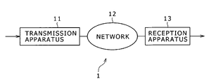
- FIG. 1 shows an example of a configuration of a communication system to which the present invention is applied.
- the communication system 1 shown includes a transmission apparatus 11 which transmits data, and a network 12 represented by a LAN (Local Area Network), the Internet or the like and having the transmission apparatus 11 connected thereto.
- the communication system 1 further includes a reception apparatus 13 which is connected to the network 12 and receives data transmitted from the transmission apparatus 11 .
- the transmission apparatus 11 transmits, when it acquires contents data to be transmitted (transmission data) such as stream data supplied thereto from the outside, the transmission data to the reception apparatus 13 set as a transmission destination of data through the network 12 . Thereupon, the transmission apparatus 11 divides the transmission data into packets and transmits the packets using a predetermined protocol such as the UDP (User Datagram Protocol). Further, the transmission apparatus 11 produces redundant data for a data restoration process from the transmission data as hereinafter described. The transmission apparatus 11 divides also the redundant data into packets and transmits the packets to the reception apparatus 13 together with the base data (transmission data).
- transmission data contents data to be transmitted
- reception apparatus 13 set as a transmission destination of data through the network 12 .
- the transmission apparatus 11 divides the transmission data into packets and transmits the packets using a predetermined protocol such as the UDP (User Datagram Protocol). Further, the transmission apparatus 11 produces redundant data for a data restoration process from the transmission data as hereinafter described.
- the transmission apparatus 11 divides
- the reception apparatus 13 When the reception apparatus 13 receives packets supplied thereto from the transmission apparatus 11 , it restores original transmission data (contents data) based on the received packets and supplies the restored contents data to the outside. Thereupon, the reception apparatus 13 restores a packet (packet for transmission data) which has not been received successfully, that is, a lost packet, using the received redundant data.
- the transmission apparatus 11 produces, in addition to transmission data, a plurality of redundant data for error correction against packet loss produced from the transmission data and transmits the redundant data to the reception apparatus 13 together with the transmission data.
- the reception apparatus 13 performs a restoration process of original transmission data which have not been received successfully based on the redundant data (received redundant data). Through the process, the reception apparatus 13 can restore the lost data without issuing a re-sending request to the transmission apparatus 11 .
- FIG. 2 shows an example of a detailed configuration of the transmission apparatus 11 . Variation of transmission data processed by the transmission apparatus 11 is illustrated in FIG. 3 .
- a data dividing section 31 of the transmission apparatus 11 divides transmission data such as contents data supplied thereto from the outside of the transmission apparatus 11 into blocks of a predetermined data size and supplies the blocks to a block dividing section 32 .
- the data dividing section 31 accumulates the transmission data supplied thereto into a buffer (not shown) built therein and supplies, every time data of the predetermined data size are accumulated, the accumulated data as a block to the block dividing section 32 .
- transmission data 51 supplied to the transmission apparatus 11 are divided into a plurality of blocks 52 of a predetermined data size unit by the data dividing section 31 .
- the transmission data 51 are divided into three blocks 52 .
- the block dividing section 32 divides the transmission data in a block unit supplied thereto from the data dividing section 31 further so as to have a predetermined data size similarly to the data dividing section 31 .
- the block dividing section 32 divides the transmission data in a block unit so as to have a data size (packet size) for packetization to produce data for a packet (packet data).
- the block dividing section 32 supplies the produced packet data to a redundant data production section 33 and an application data production section 34 .
- each of the blocks 52 is divided into base data 53 , which are packet data of a data size used in packetization, by the block dividing section 32 .
- each of the blocks 52 is divided into six base data 53 .
- the dividing number is determined depending upon the data size of packet data and the data size of a block, and one block may be divided into any number of packet data.
- the redundant data production section 33 acquires packet data (base data) obtained by dividing the original transmission data for one block, it produces redundant data to be used for restoration of a lost packet on the receiver side based on the acquired base data for one block. More particularly, the redundant data production section 33 selects arbitrary base data from within the base data for one block, and synthesizes the selected base data by EOR (Exclusive OR) arithmetic operation to obtain redundant data. A more particular production method is hereinafter described.
- redundant data for a restoration process are obtained by synthesis of a plurality of base data by EOR operation and cannot be utilized as they are as base data.
- the redundant data substantially contain contents of the base data. Accordingly, since the redundant data overlap in information with the base data, the data for a restoration process are hereinafter referred to as “redundant data”. Further, the redundant data have a data size equal to that of the base data as hereinafter described, and also the redundant data are packetized and transmitted.
- packet data data of the packet size
- base data packet data produced by dividing transmission data
- redundant data packet data for lost packet restoration produced based on the base data
- the redundant data production section 33 supplies the produced redundant data to the application data production section 34 .
- the application data production section 34 adds a header to each of the base data supplied thereto from the block dividing section 32 and the redundant data supplied thereto from the redundant data production section 33 to produce application data.
- application data including base data to which a header is added and application data including redundant data to which a header is added are available. Contents of the header are hereinafter described.
- the application data production section 34 supplies the produced application data to a UDP packetization section 35 .
- OSI layer model Open System Interconnection layer model
- ISO International Organization for Standardization
- the UDP packetization section 35 to which the application data are supplied packetizes the received application data based on the UDP protocol and supplies the thus produced UDP packets to a buffer 36 .
- the UDP packet 61 includes a UDP header 62 of 64 bits and application data 63 .
- the UDP header 62 includes information of a port number of a transmission source, a port number of a transmission destination, a data length of the application data 63 , a check sum and so forth.
- the data size of the application data has a predetermined value determined arbitrarily and usually is approximately 1K bytes.
- the buffer 36 is formed from a semiconductor memory such as a RAM (Random Access Memory) and accumulates UDP packets supplied thereto from the UDP packetization section 35 . Then, the buffer 36 outputs the accumulated UDP packets under the control of an output control section 37 .
- a semiconductor memory such as a RAM (Random Access Memory)
- the output control section 37 acquires the UDP packets in an arbitrary (random) order and supplies them to an IP (Internet Protocol) processing section 38 .
- IP Internet Protocol
- the buffer 36 and the output control section 37 change (shuffle) the outputting order of UDP packets produced by the UDP packetization section 35 such that the UDP packets containing base data and the UDP packets containing the redundant data are outputted in an arbitrary order.
- the receiver side upon transmission of packets, the receiver side sometimes fails to receive a plurality of successive packets because of loss in a burst in a network or the like. Further, as hereinafter described, the restoration capacity of the reception apparatus 13 in restoration of lost base data substantially increases in proportion to the number of received redundant data. Accordingly, when the transmission apparatus 11 outputs base data and reproduction data individually in order, if such burst packet loss as mentioned above occurs in a concentrated manner with the redundant data, then there is the possibility that the restoration capacity deteriorates extremely.
- the buffer 36 and the output control section 37 of the transmission apparatus 11 shuffle UDP packets to change the outputting order of the UDP packets such that base data and redundant data are transmitted in a mixed manner and in a random order as described above. Consequently, even if burst packet loss occurs upon transmission of packets, concentration of the loss upon redundant data can be suppressed, also the withstanding property against burst packet loss can be enhanced.
- the transmission apparatus 11 can transmit data with a higher degree of accuracy to the reception apparatus 13 , and the communication system 1 can implement transmission and reception of data with a higher degree of accuracy.
- the UDP packets are shuffled so that they are transmitted in an arbitrary outputting order as transmission packets 55 .
- the processes of the UDP packetization section 35 through the output control section 37 are processes of the transport layer of the OSI layer model.
- the IP processing section 38 performs a process of the network layer of the OSI layer model to convert UDP packets supplied thereto from the output control section 37 into IP packets based on the IP protocol, and supplies the IP packets to an Ethernet (R) processing section 39 .
- the Ethernet (R) processing section 39 performs processes of the data link layer and the physical layer based on standards of the Ethernet (R) to further packetize the IP packets supplied thereto from the IP processing section 38 and outputs the resulting packets to the network 12 through a cable 40 so that the packets may be transmitted to the reception apparatus 13 .
- the packets outputted from the Ethernet (R) processing section 39 are supplied to the reception apparatus 13 through the network 12 .
- FIG. 5 shows an example of a detailed configuration of the redundant data production section 33 .
- base data supplied from the block dividing section 32 shown in FIG. 2 are supplied to and held by a base data holding section 71 .
- the base data holding section 71 supplies the base data to a determinant production section 72 .
- the determinant production section 72 issues a request for a coefficient matrix to be used for production of a determinant for production of redundant data to a coefficient matrix supplying section 73 as indicated by a broken line arrow mark in FIG. 5 .
- the coefficient matrix has M rows and N columns and includes factors any of which is “1” or “0”.
- the coefficient matrix is used for selection of base data to be used for EOR operation.
- all redundant data are determined by integration of the coefficient matrix and another matrix which includes the base data as factors thereof. Accordingly, the rows of the coefficient matrix correspond to redundant data different from each other, and the factors of the rows are integrated with base data different from each other.
- the individual redundant data represent results of EOR operation of those factors of the coefficient matrix which have the value “1” and the integrated base data.
- the coefficient matrix supplying section 73 When the coefficient matrix supplying section 73 receives such a request for a coefficient matrix as described above, it supplies, in response to the request, a coefficient matrix produced in advance from pseudo-random numbers using a linear congruence method to the determinant production section 72 .
- the determinant production section 72 uses the coefficient matrix and base data for one block to produce a determinant for production of redundant data for the block. More particularly, the determinant production section 72 produces such a determinant as given by the following expression (1):
- the first term on the right side represents a coefficient matrix of M rows and N columns and is a coefficient matrix supplied from the coefficient matrix supplying section 73 .
- the second term on the right side represents a matrix of the base data D (D 1 to D N ) while the matrix on the left side represents redundant data S (S 1 to S M ) calculated from the determinant.
- the expression (1) not addition but EOR operation for each bit is performed. The value of each factor of the coefficient matrix is determined at random as hereinafter described.
- the expression (1) represents that the redundant data S 1 to S M are results of EOR operation of base data arbitrarily selected from among the base data D 1 to D N .
- the determinant production section 72 supplies the determinant to a determinant arithmetic operation section 74 . It is to be noted that the determinant indicates a same thing as simultaneous equations. This similarly applies to the following description.
- the determinant arithmetic operation section 74 arithmetically operates such a determinant as given by the expression (1).
- the determinant arithmetic operation section 74 integrates the column factors of each row of the coefficient matrix of the first term of the right side of the expression (1) with the respective corresponding row components (base data D 1 to D N ) of the second term of the right side. Then, the determinant arithmetic operation section 74 uses results of the integration to perform EOR operation for each of the corresponding bits to calculate one EOR operation result for each row and sets the calculated EOR operation results as redundant data S.
- the rows of the matrix of the first term are integrated with the column of the matrix of the second term. More particularly, the rows of the matrix of the first term and the column of the matrix of the second row are integrated for each corresponding factors. For example, as regards the first row of the first term, the factor of the ith column of the row is integrated with the factor of the ith row of the column of the second term. After the integration is performed in this manner, all of the results of the integrations of the factors are added.
- the matrix of the first term is a matrix of N columns and the matrix of the second term is a matrix of N rows
- the N integration results are added, and a result of the addition is set as an integration result of the row of the matrix of the first term and the column of the matrix of the second term.
- arithmetic operation is performed in an arithmetic operation procedure basically similar to such an arithmetic operation procedure as just described.
- the base data D and the redundant data S are bit trains of binary numbers, EOR operation for each bit is used in place of the addition process of integration results of factors in the arithmetic operation procedure described above wherein decimal numbers are used.
- the determinant arithmetic operation section 74 integrates the rows of the coefficient matrix of the first term of the right side of the expression (1) with the column of the matrix (matrix which includes the base data D 1 to D N as factors thereof) of the second term on the right side. More particularly, the factors of the columns of each row of the coefficient matrix of the first term on the right side are integrated with the factors (base data D 1 to D N ) of the matrix of the second term on the right side, respectively.
- the integration results of the factors become either the factors (base data D 1 to D N ) of the second term on the right side or “0” (more particularly, a bit train which includes a number of bits equal to the number of bits of the base data D and wherein the values of the bits are “0”).
- the determinant arithmetic operation section 74 synthesizes the integration results of the factors by EOR operation for the individual bits corresponding to each other as described above.
- the EOR operation is described.
- the value of the EOR operation result of the value “0” and the value “0” is “0”
- the value of the EOR operation result of the value “0” and the value “1” is “1”
- the value of the EOR operation result of the value “1” and the value “0” is “1”
- the value of the EOR operation result of the value “1” and the value “1” is “0”.
- the EOR operation result of a bit train of “11110000” and another bit train of “10101010” is “01011010”.
- the determinant arithmetic operation section 74 repeats such EOR operation as described above to synthesize all of the integration results of the factors. Then, this EOR operation result is set as one redundant data S.
- Such arithmetic operation as described above is repeated for the rows of the coefficient matrix of the first term on the right side of the expression (1) to determine the redundant data S 1 to S M all represented as the factors of the matrix of the first term on the left side of the expression (1).
- the integration results of the factors of the coefficient matrix and the base data D 1 to D N become either the factors (base data D 1 to D N ) of the second term on the right side or “0”. Accordingly, where the integration is represented in other words, the determinant arithmetic operation section 74 selects or extracts the base data D to be used for production of redundant data S by integration of the factors and the base data D 1 to D N .
- the value of each of the bits of the synthesis result is “1” where the number of those integration results whose value is “1” is an odd number from among the bits of the integration results of the EOR operation corresponding to the bit, but is “0” where the number of those integration results whose value is “1” is an even number.
- the determinant arithmetic operation section 74 tabulates the values of the bits of the integration results of the individual factors for each of the bits corresponding to each other and, if the number of those integration results whose value is “1” is an odd number, the determinant arithmetic operation section 74 sets the value of a bit of the redundant data S corresponding to the bit to “1”, but if the number of those integration results whose value is “1” is an even number, the determinant arithmetic operation section 74 sets the value of a bit of the redundant data S corresponding to the bit to “0”.
- the determinant arithmetic operation section 74 selects base data D from among the base data D 1 to D N in accordance with a predetermined method. Then, if the number of those bits of the selected base data D corresponding to each other which have the value “1” is an odd number, then the determinant arithmetic operation section 74 sets the value of a bit of the redundant data S corresponding to the bits to “1”. However, if the number of those bits which have the value “1” is an even number, the determinant arithmetic operation section 74 sets the value of a bit of the redundant data S corresponding to the bits to “0”.
- the determinant arithmetic operation section 74 performs arithmetic operation in such a manner as described above to determine redundant data S (S 1 to S M ) and supplies the redundant data S to a solution outputting section 75 .
- the transmission apparatus 11 produces such packet data as illustrated in FIG. 6 from the transmission data and transmits the packet data.
- base data 81 are formed from packet data 81 - 1 to 81 -N
- redundant data 82 are formed from packet data 82 - 1 to 82 -M.
- the packet data 81 - 1 to 81 -N of the base data 81 correspond to the base data D 1 to D N , respectively
- the packet data 82 - 1 to 82 -M of the redundant data 82 are EOR operation results (exclusive OR results) of the base data selected arbitrarily from among the base data D 1 to D N .
- the solution outputting section 75 supplies the EOR operation results as redundant data S to the application data production section 34 shown in FIG. 2 at a predetermined timing.
- FIG. 7 shows an example of a detailed configuration of the coefficient matrix supplying section 73 shown in FIG. 5 .
- the coefficient matrix supplying section 73 includes a seed data holding section 91 formed from a storage device such as a RAM and used to hold seed data to be used for generation of a pseudo-random number hereinafter described. It is to be noted that, although any value may be used as the seed data, it is assumed that, in the following description, an arbitrary constant determined in advance is used as the seed data.
- a pseudo-random number production section 92 issues a request for the seed data to the seed data holding section 91 (broken line arrow mark in FIG. 7 ) at a predetermined timing such as, for example, when the power supply is made available.
- the seed data holding section 91 supplies the seed data to the pseudo-random number production section 92 in accordance with the request.
- the pseudo-random number production section 92 performs the modulo arithmetic operation of the expression (2), for example, by 32-bit arithmetic operation.
- the pseudo-random number production section 92 After the pseudo-random number production section 92 arithmetically operates the expression (2) to calculate the variable rand (pseudo-random number), it supplies the value to a pseudo-random number buffer 93 so as to be held by the same and further supplies the value to a coefficient decision section 94 .
- the rand held in the pseudo-random number buffer 93 is read out again by the pseudo-random number production section 92 and is substituted into the variable rand on the right side of the expression (2) in and utilized by the pseudo-random number arithmetic operation in the next operation cycle.
- the coefficient decision section 94 decides the values of the factors of the coefficient matrix one by one based on the values of the acquired pseudo-random number. At this time, the coefficient decision section 94 sets, for example, a threshold value for the values of the acquired pseudo-random numbers and decides, if the value of an acquired pseudo-random number is equal to or higher than the threshold value, then the coefficient decision section 94 decides that the value of the factor of the coefficient matrix is “1”. However, if the value is lower than the threshold value, then the coefficient decision section 94 decides that the value of the factor of the coefficient matrix is “0”. Then, the coefficient decision section 94 supplies a result of the decision to a coefficient matrix holding section 96 so as to be held by the same.
- the coefficient decision section 94 acquires a coefficient production probability p held by the coefficient production probability holding section 95 and determines the value of the threshold value based on the value of the coefficient production probability p. In particular, the coefficient decision section 94 sets the threshold value so that the ratio of those factors which have the value “1” in all of the factors of the coefficient matrix formed from the values of “0” and “1” may become equal to (approach) the value of the coefficient production probability p.
- the coefficient production probability p is a constant determined in advance which is higher than “0” but lower than “1” and stochastically designates what rate the factors which have the value “1” occupy among all factors of the coefficient matrix.
- the coefficient decision section 94 sets the threshold value so that the number of those factors which have the value “0” and the number of those factors which have the value “1” in the generated coefficient matrix may become substantially equal to (approach) 1:1. For example, if it is assumed that the values of the pseudo-random number is distributed at an equal probability to all of 32 bits, the coefficient decision section 94 sets the threshold value to “2147483648”.
- the decision results (“0” or “1”) are supplied one by one from the coefficient decision section 94 to a coefficient matrix holding section 96 in such a manner as described above, and the coefficient matrix holding section 96 produces and holds a coefficient matrix of M rows ⁇ N columns whose factors are the decision results.
- a coefficient matrix outputting section 97 issues a request for and acquires the held coefficient matrix to and from the coefficient matrix holding section 96 and supplies the acquired coefficient matrix to the determinant production section 72 .
- the coefficient matrix supplying section 73 produces a coefficient matrix and supplies the coefficient matrix in response to a request in such a manner as described above.
- the coefficient matrix may naturally be calculated at any timing only if it is before a request for a coefficient matrix is received. Further, the coefficient matrix may be common to all blocks or may otherwise be produced for every block so that matrices independent of each other may be applied to the blocks. However, where a coefficient matrix is used commonly to blocks as indicated by a curve 101 in FIG. 8 , the restoration capacity on the receiver side is higher than where a coefficient matrix is produced newly for every block as indicated by another curve 102 .
- FIG. 8 is a graph illustrating a relationship of the restoration capacities, and the axis of abscissa represents the number of lost packets and the axis of ordinate represents the restoration capacity (reciprocal to the frequency of impossibility in restoration).
- FIG. 9 shows an example of a detailed configuration of the application data production section 34 shown in FIG. 2 .
- a base data counter 112 , a block counter 113 and a redundant data counter 123 are initialized first.
- the count values of the base data counter 112 and the block counter 113 are set to “0” while the count value of the redundant data counter 123 is set to an offset value supplied from an offset value supplying section 122 .
- the offset value supplying section 122 holds a predetermined value such as, for example, the data number of base data in one block as an offset value and supplies the value to the redundant data counter 123 so that the packet number of redundant data may be set so as not to overlap with any packet number of base data.
- a base data acceptance section 111 causes the base data counter 112 and the block counter 113 to count up.
- the base data acceptance section 111 causes only the base data counter 112 to count up.
- the base data counter 112 and the block counter 113 supply the count values thereof to a header addition section 114 at a predetermined timing.
- the base data acceptance section 111 initializes the count value of the base data counter 112 after the last packet data of a block are processed.
- the base data acceptance section 111 supplies the base data to the header addition section 114 .
- the header addition section 114 adds the count values supplied thereto from the base data counter 112 and the block counter 113 as a header to the base data supplied thereto from the base data acceptance section 111 as seen in FIG. 10A to produce application data.
- the application data 131 include a block number 132 and an base data packet number 133 added as a header and base data 134 .
- the block number 132 is a number for identification of the block, and values different from one another are allocated to different blocks.
- the value of the block number 132 is the count value supplied from the block counter 113 .
- the base data packet number 133 is a number for identification of the base data, and values different from one another are allocated to different base data.
- the value of the base data packet number 133 is the count value supplied from the base data counter 112 .
- the value (“0” in FIG. 11 ) of the block number 132 is common to the application data, and the value of the base data packet number 133 increases one by one (in FIG. 11 , “0” to “999”).
- Such a header as described above is added to the base data 134 to produce the application data 131 .
- the block number 132 is information for specifying to which block the packet data acquired by the reception apparatus 13 belong (to which block data the packet data correspond)
- the base data packet number 133 is information for specifying a packet decided as the lost packet by the reception apparatus 13 . Since such information is added to the packet data to produce application data, the reception apparatus 13 can refer to the information in a process of the application layer. Further, although a packet number is added also to an IP packet and so forth, this is information for use for re-sending control and so forth but cannot be utilized for a restoration process and so forth of data and is different in application and characteristic from the information described above.
- a redundant data acceptance section 121 causes the redundant data counter 123 to count up when redundant data are supplied thereto from the redundant data production section 33 .
- the redundant data counter 123 and the block counter 113 supply the count values thereof to the header addition section 114 at a predetermined timing.
- the redundant data acceptance section 121 initializes the count value of the redundant data counter 123 , the offset value supplying section 122 supplies the offset value to the redundant data counter 123 .
- the redundant data acceptance section 121 supplies redundant data to the header addition section 114 after the redundant data counter 123 is adjusted.
- the header addition section 114 adds the count values supplied thereto from the redundant data counter 123 and the block counter 113 as a header to the redundant data supplied thereto from the redundant data acceptance section 121 as seen in FIG. 10B to produce application data.
- the application data 141 include a block number 142 and a redundant data packet number 143 added as a header and redundant data 144 .
- the block number 142 is the count value supplied from the block counter 113 .
- the redundant data packet number 143 is a number for identification of the redundant data, and values different from one another are allocated to different redundant data.
- the value of the redundant data packet number 143 is the count value supplied from the redundant data counter 123 .
- the value (“0” in FIG. 11 ) of the block number 142 is common to the application data, and the value of the redundant data packet number 143 increases one by one (in FIG. 11 , “1000” to “1099”). In the case of FIG. 11 , since the number of base data per one block is set to 1,000, the offset value is set to “1000”.
- Such a header as described above is added to the redundant data 144 to produce the application data 141 .
- the block number 142 is information for specifying to which block the packet data acquired by the reception apparatus 13 belong
- the redundant data packet number 143 is information for aligning the packet acquired by the reception apparatus 13 . Since such information is added to the packet data to produce application data, the reception apparatus 13 can refer to the information in a process of the application layer. Further, although a packet number is added also to an IP packet and so forth, this is information for use for re-sending control and so forth but cannot be utilized for a restoration process and so forth of data and is different in application and characteristic from the information described above.
- application data include either base data or redundant data.
- the application data are packetized based on the UDP, the IP or the like as described above and supplied to the reception apparatus 13 through the network.
- the reception apparatus 13 can identify a block of received data and process the received data in a unit of a block as hereinafter described.
- the reception apparatus 13 can specify lost base data (which the reception apparatus 13 has failed to receive) based on the packet number as hereinafter described.
- the reception apparatus 13 can align the redundant data and can cut out, when to restore base data, a necessary portion readily and accurately from a coefficient matrix of M rows and N columns prepared in advance, a determinant for restoring the base data can be produced readily and accurately.
- FIG. 12 shows an example of a detained configuration of the reception apparatus 13 shown in FIG. 1 .
- a packet supplied to the reception apparatus 13 through the network 12 is supplied to an Ethernet (R) processing section 221 through a cable 210 .
- the Ethernet (R) processing section 221 performs processes of the data link layer and the physical layer based on the Ethernet (R) standards to extract an IP packet from the packet supplied thereto, and supplies the IP packet to an IP processing section 222 .
- the IP processing section 222 performs a process of the network layer based on the IP protocol to extract a UDP packet from the IP packet supplied thereto, and supplies the UDP packet to an application data extraction section 223 .
- the application data extraction section 223 performs a process of the transport layer based on the UDP protocol to extract application data from the UDP packet, and supplies the application data to a buffer 224 .
- the buffer 224 holds the application data and manages the application data in a unit of a block based on the block number added to the application data. Then, the buffer 224 supplies the application data to a data separation section 225 for each block.
- the data separation section 225 classifies the application data supplied thereto depending upon whether the application data contain base data or redundant data based on the packet number added to the application data. Then, the data separation section 225 supplies application data containing base data to a packet loss decision section 226 and supplies application data containing redundant data to a loss packet restoration section 228 .
- the reception apparatus 13 Although a packet transmitted from the transmission apparatus 11 is transmitted toward the reception apparatus 13 , sometimes it is not received by the reception apparatus 13 from various causes. Accordingly, the reception apparatus 13 sometimes fails to receive some of packets which form one block as seen in FIG. 13 .
- three packet data 241 A to 241 C of base data 241 and one packet data 242 A of redundant data 242 supplied from the transmission apparatus 11 are lost and not received by the reception apparatus 13 .
- the reception apparatus 13 cannot restore the block data only using the base data 241 received successfully because of absence of the base data D 1 to D 3 . Therefore, in such an instance, the reception apparatus 13 uses the redundant data 242 received successfully to restore the lost packet data 241 A to 241 C.
- the packet loss decision section 226 decides based on the packet numbers of the base data supplied thereto whether or not a packet is lost. If the packet loss decision section 226 decides that a packet is lost, then it supplies the application data including the base data to the block data restoration section 227 , also at the same time, along with the decision results, the packet loss decision section 226 supplies the application data including the base data to the loss packet restoration section 228 . On the other hand, if no packet is lost, then the packet loss decision section 226 supplies the application data including the base data to a block data restoration section 227 .
- the block data restoration section 227 synthesizes the base data of the application data supplied thereto from the packet loss decision section 226 to restore the block data. On the other hand, if the reception apparatus 13 decides loss of a packet and decides shortage of base data, then it uses the base data restored by the loss packet restoration section 228 . After the block data restoration section 227 restores the block data, it supplies the block data to a block synthesis section 229 .
- the loss packet restoration section 228 performs EOR operation using the application data supplied thereto from the packet loss decision section 226 and containing the base data and the application data supplied thereto from the data separation section 225 and containing the redundant data to solve a determinant to restore the lost base data. Then, the loss packet restoration section 228 supplies the restored base data to the block data restoration section 227 .
- the block synthesis section 229 temporarily holds the block data supplied thereto from the block data restoration section 227 and combines blocks by adjusting timings at which the block data are to be outputted to produce a single series of continuous reception data (that is, transmission data of the transmission apparatus 11 ). Then, the block synthesis section 229 outputs the reception data to the outside of the reception apparatus 13 .
- the processes executed by the buffer 224 and succeeding components described above are processes of the application layer, presentation layer and session layer of the OSI layer model.
- the reception apparatus 13 Since the reception apparatus 13 receives data and restores lost base data by EOR operation in this manner, it can implement a high-speed restoration process of a high restoration performance without increasing the production cost and can receive data with a high degree of accuracy.
- FIG. 14 shows an example of a detailed configuration of the loss packet restoration section 228 .
- decision results supplied from the packet loss decision section 226 of FIG. 12 and application data of base data are supplied to a decision result acquisition section 251 .
- the decision result acquisition section 251 supplies the application data of the base data to a base data holding section 252 and supplies, based on the decision results, an instruction to reproduce a determinant to a determinant production section 253 .
- the determinant production section 253 After the determinant production section 253 receives the instruction to produce a determinant from the decision result acquisition section 251 , it issues a request for and acquires base data to and from the base data holding section 252 . Further, the determinant production section 253 issues a request for and acquires redundant data to and from the redundant data holding section 254 and further issues a request for and acquires a coefficient matrix to and from a coefficient matrix supplying section 255 . It is to be noted that the coefficient matrix supplying section 255 has a configuration basically similar to that of the coefficient matrix supplying section 73 shown in FIG. 7 and operates similarly. Therefore, detailed description of the coefficient matrix supplying section 255 is omitted herein to avoid redundancy.
- the determinant production section 253 produces a determinant for calculating redundant data Q for arithmetic operation necessary for a determinant for arithmetic operation of lost base data.
- Lost base data are determined using received base data and redundant data as hereinafter described.
- the received redundant data sometimes include also information of the received base data
- the information of the received base data are substituted into the received redundant data at a first stage to produce redundant data Q for arithmetic operation formed only from EOR operation results of the lost base data.
- the determinant production section 253 produces the following expression (3) in order to produce the redundant data Q for arithmetic operation:
- the addition represents EOR operation.
- the factors Q 1 to Q M-L of the matrix on the left side of the expression (3) are redundant data for arithmetic operation corresponding to the received redundant data J 1 to J M-L which are factors of the matrix of the third term on the right side, respectively.
- the factors R 1 to R N-K of the matrix of the second term on the right side of the expression (3) represent the received base data.
- the coefficient matrix of the first term on the right side is a coefficient matrix of M-L rows and N-K columns cut out from the coefficient matrix of M rows and N columns produced by the coefficient matrix supplying section 255 in advance.
- the determinant production section 253 aligns the received redundant data J 1 to J M-L based on the redundant data packet numbers and aligns the received base data R 1 to R N-K based on the base data packet numbers. Further, the determinant production section 253 cuts out, from the coefficient matrix of M rows and N columns held by the coefficient matrix supplying section 255 , the factors of a portion corresponding to the received base data R 1 to R N-K and the received redundant data J 1 to J M-L to produce the expression (3).
- the redundant data Q 1 to Q M-L for arithmetic operation are results of removal of the EOR operation results of the received base data R 1 to R N-K from the received redundant data J 1 to J M-L , respectively. It is to be noted that, since the redundant data are EOR operation results of the base data, the information of the received base data included in the received redundant data J can be removed by performing EOR operation of the received base data R again.
- the redundant data Q 1 to Q M-L for arithmetic operation determined in such a manner as described above make EOR operation results of the lost base data P 1 to P K , respectively.
- the determinant production section 253 supplies the determinant to a determinant arithmetic operation section 256 .
- the determinant arithmetic operation section 256 arithmetically operates the determinant to calculate redundant data Q for arithmetic operation and returns the redundant data Q for arithmetic operation to the determinant production section 253 .
- the determinant production section 253 acquires the redundant data Q for arithmetic operation, it now uses the redundant data Q for arithmetic operation to produce a determinant for restoration of the base data.
- the determinant production section 253 cuts out, based on the packet numbers of the received redundant data and the packet numbers of the lost base data, a portion (M-L rows and K columns) corresponding to the packet numbers from the coefficient matrix of M rows and N columns held in the coefficient matrix supplying section 255 and produces such a determinant as given by the following expression (4):
- the first term on the left side is the cut out coefficient matrix and the factors of the matrix of the second term on the left side are the lost data P 1 to P K while the factors of the matrix on the right side are the redundant data Q1 to QM-L for arithmetic operation.
- the value of M-L representative of the number of the redundant data Q 1 to Q M-L for arithmetic operation must be higher than the value of K which indicates the number of the lost base data.
- the coefficient matrix in the expression (4) it is necessary for the coefficient matrix in the expression (4) to have the number of rows more than the number of columns. In other words, in order to restore all of the lost base data, it is at least necessary for the reception apparatus 13 to receive a number of redundant data greater than the number of the lost base data.
- the determinant production section 253 supplies the determinant to the determinant arithmetic operation section 256 .
- the determinant arithmetic operation section 256 uses, for example, the Gaussian elimination to determine solutions to the lost base data P 1 to P K .
- the solution determination method is hereinafter described, any method may be used only if it can calculate lost base data.
- the determining arithmetic operation section 256 supplies the solutions to a solution outputting section 257 .
- the solution outputting section 257 uses the solutions to restore the application data of the lost base data and supplies the restored application data to the block data restoration section 227 shown in FIG. 12 .
- the reception apparatus 13 can restore lost base data without issuing a re-sending request to the transmission apparatus 11 . Further, since redundant data for the restoration process are produced by EOR operation, the load of arithmetic operation is moderated and it is possible to reproduce redundant data readily or perform a restoration process using the redundant data. Accordingly, a high-speed restoration process of a high restoration performance can be implemented without increasing the production cost of the transmission apparatus 11 and communication with a high degree of accuracy can be achieved readily.
- the transmission apparatus 11 After supply of transmission data from the outside is started, the transmission apparatus 11 starts a data transmission process.
- the data transmission process of the transmission apparatus 11 shown in FIG. 2 is described below with reference to a flow chart of FIG. 15 .
- the data dividing section 31 of the transmission apparatus 11 divides the transmission data into blocks and supplies the divided block data to the block dividing section 32 at step S 1 .
- the block dividing section 32 further divides the block data supplied thereto into packet data and supplies the packet data as base data to the redundant data production section 33 and the application data production section 34 . It is to be noted that the following processes are executed in a unit of a block.
- the redundant data production section 33 to which the packet data are supplied executes a redundant data production process to produce redundant data by EOR operation and supplies the redundant data to the application data production section 34 at step S 3 . Details of the redundant data production process are hereinafter described with reference to a flow chart of FIG. 16 .
- step S 4 the application data production section 34 to which the base data and the redundant data are supplied executes an application data production process to produce application data and supplies the produced application data to the UDP packetization section 35 . It is to be noted that details of the application data production process is hereinafter described with reference to a flow chart of FIG. 18 .
- the UDP packetization section 35 to which the application data are supplied converts the application data into UDP packets and supplies the UDP packets to the buffer 36 .
- the buffer 36 temporarily holds the UDP packets supplied thereto, and at step S 6 , the output control section 37 extracts the UDP packets held in the buffer 36 in an arbitrary order to change the transmission order of the UDP packets.
- the output control section 37 supplies the extracted UDP packets to the IP processing section 38 .
- the IP processing section 38 converts the UDP packets supplied thereto into IP packets and supplies the IP packets to the Ethernet (R) processing section 39 .
- the Ethernet (R) processing section 39 further converts the IP packets supplied thereto into packets or the like, and transmits the packets (individually including the UDP packets) in the order changed by the output control section 37 to the network 12 (reception apparatus 13 ) through the cable 40 .
- the block dividing section 32 decides at step S 8 whether or not the process is completed for all of the blocks which form the transmission data supplied to the transmission apparatus 11 from the outside. If the block dividing section 32 decides that the transmission process for all blocks is not completed as yet, then the block dividing section 32 returns the processing to step S 2 so that the processes at the steps beginning with the step S 2 are repeated for a next block.
- the data transmission process is executed in such a manner as described above. Consequently, the transmission apparatus 11 can produce redundant data at a high speed and transmit data readily and accurately without performing a process of a heavy load such as arithmetic operation of a Galois field. Further, since the transmission apparatus 11 can shuffle packet data to change the transmission order of the packet data and transmit the packet data in an order independent of the packet numbers, also the withstanding property against burst packet loss can be enhanced. Further, since the transmission apparatus 11 performs the transmission process in this manner, the reception apparatus 13 which receives the packets transmitted from the transmission apparatus 11 can implement a high-speed restoration process of a high restoration performance without increasing the production cost. In other words, the communication system 1 can perform communication of a higher degree of accuracy readily.
- the determinant production section 72 issues a request for a coefficient matrix to the coefficient matrix supplying section 73 at step S 23 .
- the coefficient matrix supplying section 73 supplies a coefficient matrix prepared in advance to the determinant production section 72 in accordance with the request.
- the preparation process of the coefficient matrix is hereinafter described with reference to a flow chart of FIG. 17 .
- the determinant production section 72 acquires the coefficient matrix, it acquires, at step S 23 , the base data for one block held by the base data holding section 71 and produces a determinant for production of redundant data by EOR operation of arbitrary base data like the expression (1). After the determinant production section 72 produces the determinant, it supplies the determinant to the determinant arithmetic operation section 74 .
- the determinant arithmetic operation section 74 to which the determinant is supplied performs, at step S 24 , EOR operation and arithmetically operates the determinant to obtain solutions, and supplies the solutions to the solution outputting section 75 .
- the solution outputting section 75 outputs, at step S 25 , the solutions supplied thereto as redundant data for a loss packet restoration process to the application data production section 34 . Then, the processing is returned to step S 4 of FIG. 15 so that the processes at the steps beginning with step S 4 are executed.
- the redundant data production section 33 can produce redundant data readily at a high speed. Consequently, the transmission apparatus 11 can produce redundant data at a high speed without performing a process of a high load such as arithmetic operation of a Galois field, and can transmit data readily and accurately. Further, since the transmission apparatus 11 performs a transmission process in this manner, the reception apparatus 13 which receives packets transmitted from the transmission apparatus 11 can implement a high-speed restoration process of a high restoration performance without increasing the production cost. In other words, the communication system 1 can perform communication readily with a higher degree of accuracy.
- the coefficient matrix preparation process executed by the coefficient matrix supplying section 73 of FIG. 7 is described with reference to a flow chart of FIG. 17 .
- the coefficient matrix supplying section 73 executes the coefficient matrix preparation process, for example, when the power supply to the transmission apparatus 11 is made available.
- the coefficient decision section 94 of the coefficient matrix supplying section 73 which starts the coefficient matrix preparation process acquires, first at step S 41 , a coefficient production probability p from the coefficient production probability holding section 95 and sets a threshold value for determination of the value of the coefficient based on the acquired coefficient production probability p.
- the pseudo-random number production section 92 acquires the seed data held in the seed data holding section 91 and acquires a pseudo-random number which is a result of arithmetic operation in the preceding cycle held in the pseudo-random number buffer 93 .
- the pseudo-random number production section 92 produces a pseudo-random number by such a linear congruence method as represented by the expression (2) given hereinabove based on the acquired seed data.
- the pseudo-random number production section 92 supplies the pseudo-random number produced thereby to the pseudo-random number buffer 93 so as to be held by the pseudo-random number buffer 93 and supplies the pseudo-random number also to the coefficient decision section 94 .
- the coefficient decision section 94 decides whether or not the value of the pseudo-random number supplied thereto is equal to or higher than the threshold value set at step S 41 . If it is decided that the value of the pseudo-random number is equal to or higher than the threshold value, then the coefficient decision section 94 set the value of the factor of the coefficient matrix to be outputted in the present cycle to “1” at step s 45 and outputs the factor to the coefficient matrix holding section 96 . Thereafter, the processing is advanced to step S 47 .
- step S 44 determines whether the value of the pseudo-random number supplied is lower than the threshold value. If it is decided at step S 44 that the value of the pseudo-random number supplied is lower than the threshold value, then the coefficient decision section 94 advances the processing to step S 46 , at which it sets the value of the factor of the coefficient matrix to be outputted in the present cycle to “0” and outputs the factor to the coefficient matrix holding section 96 . Thereafter, the processing advances to step S 47 .
- step S 47 the coefficient matrix holding section 96 to which the factor of the coefficient matrix is supplied holds the factor of the coefficient matrix. Then, at step S 48 , the coefficient matrix holding section 96 decides from the factors held therein whether or not the coefficient matrix is completed. If it is decided that the coefficient matrix is not completed, then the processing returns to step S 42 so that the processes at the steps beginning with step S 42 are executed by the pertaining sections before a next factor is supplied.
- step S 48 If it is decided at step S 48 that all factors are supplied and the coefficient matrix is completed, then the coefficient matrix holding section 96 ends the coefficient matrix preparation process.
- the coefficient matrix thus produced and held in coefficient matrix holding section 96 is requested from the coefficient matrix outputting section 97 which is requested from the determinant production section 72 to be output.
- the redundant data production section 33 can produce redundant data using base data selected at random from among the base data for one block. Consequently, one-sidedness of the distribution of base data to be used for production of redundant data can be suppressed. Accordingly, in the restoration process of the reception apparatus 13 , dependency of the possibility of base data restoration upon the contents of lost redundant data can be suppressed. Further, through such processes as described above, the coefficient decision section 94 can stochastically control the number of base data to be included in redundant data with the coefficient production probability p.
- the base data acceptance section 111 of the application data production section 34 initializes the base data counter 112 and the block counter 113 so that they individually have, for example, the value “0” at step S 61 . Also the redundant data acceptance section 121 of the application data production section 34 initializes the redundant data counter 123 so that the count value of the redundant data counter 123 is set to an offset value supplied from the offset value supplying section 122 .
- the base data acceptance section 111 decides whether or not base data are accepted. If it is decided that base data supplied from the block dividing section 32 are accepted, then the processing advances to step S 63 , at which it is decided whether or not the accepted base data are the first packet data in a block. If it is decided that the accepted base data are the first packet data of a block, then the base data acceptance section 111 advances the processing to step S 64 , at which it causes the block counter 113 to count up so that the count value of the block counter 113 is incremented by “1”. Thereafter, the processing advances to step S 65 .
- step S 63 if it is decided at step S 63 that base data of the block have been accepted already and the accepted data are not the first packet of a block, then the base data acceptance section 111 bypasses the step S 64 and advances the processing directly to step S 65 .
- the base data acceptance section 111 causes the base data counter 112 to count up so that the count value of the base data counter 112 is incremented by “1”, and supplies the accepted base data to the header addition section 114 .
- the header addition section 114 to which the base data are supplied acquires, at step S 66 , the count value from each of the base data counter 112 and the block counter 113 and adds the count value of the block counter 113 as the block number and the count value of the base data counter 112 as the base data packet number to the base data.
- the header addition section 114 supplies the base data to which the count values are added as application data to the UDP packetization section 35 .
- the header addition section 114 advances the processing to step S 68 .
- the base data acceptance section 111 bypasses the steps S 63 to S 67 and advances the processing directly to step S 68 .
- the redundant data acceptance section 121 decides whether or not redundant data are accepted. If it is decided that redundant data supplied from the redundant data production section 33 are accepted, then the processing advances to step S 69 , at which the redundant data acceptance section 121 causes the redundant data counter 123 to count up so that the count value of the redundant data counter 123 is incremented by “1” and supplies the accepted redundant data to the header addition section 114 .
- the header addition section 114 to which the redundant data are supplied acquires, at step S 70 , the count value from each of the block counter 113 and the redundant data counter 123 and adds the count value of the block counter 113 as the block number and the count value of the redundant data counter 123 as the redundant data packet number to the redundant data. Then at step S 71 , the header addition section 114 supplies the redundant data to which the count values are added as application data to the UDP packetization section 35 .
- the header addition section 114 advances the processing to step S 72 .
- the redundant data acceptance section 121 bypasses the steps S 69 to S 71 and advances the processing directly to step S 72 .
- the header addition section 114 decides whether or not all of the base data and the redundant data of the block are processed. If it is decided that some packet data have not been processed as yet, then the processing returns to step S 62 so that the processes at the steps beginning with step S 62 are repeated. If it is decided at step S 72 that all packet data are processed, then the header addition section 114 ends the application data production process and returns the processing to step S 5 of FIG. 15 .
- the reception apparatus 13 can identify a block of received data and process the received data in a unit of a block.
- the reception apparatus 13 can specify lost base data (data which the reception apparatus 13 fails to receive) based on the packet numbers as hereinafter described.
- the reception apparatus 13 can align the redundant data when to restore the base data as hereinafter described, a determinant to be used for restoration of the base data can be produced readily and accurately.
- the header addition section 114 adds a base data packet number to each base data and adds a redundant data packet number to each redundant data, when the reception apparatus 13 tries to restore the base data, it can cut out a necessary portion from a coefficient matrix of M rows and N columns prepared in advance readily and accurately. Consequently, a determinant for restoration of the base data can be produced readily and accurately.
- the Ethernet (R) processing section 221 receives the packet at step S 91 .
- the Ethernet (R) processing section 221 extracts an IP packet from the packet and supplies the IP packet to the IP processing section 222 .
- the IP processing section 222 extracts a UDP packet from the IP packet and supplies the UDP packet to the application data extraction section 223 .
- the application data extraction section 223 to which the UDP packet is supplied extracts application data from the UDP packet and supplies the application data to the buffer 224 at step S 92 .
- the buffer 224 holds the application data supplied thereto.
- the buffer 224 decides whether or not a predetermined interval of time elapses thereby to decide whether or not application data for one block are held.
- the buffer 224 accumulates application data of blocks for a predetermined period of time, and when the predetermined time elapses, the buffer 224 supplies the application data of the object blocks accumulated till then to the data separation section 225 .
- step S 94 If it is decided at step S 94 that the predetermined time does not elapse and application data for one block are not held as yet, then the buffer 224 returns the processing to step S 91 so that the processes at the steps beginning with the step S 91 are repeated. In other words, the reception apparatus 13 waits that the predetermined time elapses with the buffer 224 while the processes at steps S 91 to S 94 are repeated.
- step S 95 the data separation section 225 separates the application data supplied thereto into base data and redundant data based on the packet number and so forth of them. Then, the data separation section 225 supplies the application data of base data to the packet loss decision section 226 and supplies the application data of redundant data to the loss packet restoration section 228 .
- the packet loss decision section 226 to which the application data are supplied confirms, at step S 96 , a lost packet based on the base data packet numbers of the application data supplied thereto, and decides, at step S 97 , whether or not base data are lost. If it is decided that base data are lost, then the packet loss decision section 226 supplies the application data of base data to the block data restoration section 227 and supplies the decision result and the application data of base data to the loss packet restoration section 228 , whereafter the processing is advanced to step S 98 .
- the loss packet restoration section 228 executes a base data restoration process to restore the lost base data and supplies the application data of the restored base data to the block data restoration section 227 . It is to be noted that details of the base data restoration process are hereinafter described with reference to a flow chart of FIG. 20 .
- step S 99 After the loss packet restoration section 228 restores the base data, it advances the processing to step S 99 . On the other hand, if it is decided at step S 97 that all base data packet numbers are complete and no base data are lost, then the loss packet restoration section 228 supplies the application data of base data to the block data restoration section 227 and advances the processing to step S 99 bypassing the step S 98 .
- the block data restoration section 227 extracts base data from the application data supplied thereto and unites the base data to restore block data, and supplies the restored block data to the block synthesis section 229 .
- the block synthesis section 229 temporarily holds the block data supplied thereto and outputs the block data at a predetermined timing.
- the block synthesis section 229 successively outputs block data successively supplied thereto from the block data restoration section 227 to unite the block data thereby to output the united block data as reception data equivalent to the transmission data prior to the transmission to the outside of the reception apparatus 13 .
- the block synthesis section 229 decides, at step S 100 , whether or not the data reception process should be ended. If it is decided that processing of all block data as reception data is not completed as yet and hence the data reception process should not be ended, then the block synthesis section 229 returns the processing to step S 91 so that the processes at the steps beginning with the step S 91 are repeated by the pertaining sections.
- step S 100 if it is decided at step S 100 that the data reception process should be ended, then the block synthesis section 229 causes the pertaining sections to execute an ending process thereby to end the data reception process.
- the reception apparatus 13 can implement a high-speed restoration process of a high restoration performance without increasing the production cost and can receive data readily and with a high degree of accuracy.
- the decision result acquisition section 251 of the loss packet restoration section 228 acquires a decision result from the packet loss decision section 226 , it acquires application data of base data supplied thereto together with the decision result and supplies the acquired application data to the base data holding section 252 so as to be held by the same. Then, the decision result acquisition section 251 issues an instruction to produce a determinant to the determinant production section 253 .
- the determinant production section 253 starts a base data restoration process in accordance with the instruction and acquires, at step S 121 , the application data of base data from the base data holding section 252 . Then at step S 122 , the determinant production section 253 refers to the base data packet number of the acquired application data to specify the packet number of lost base data.
- the determinant production section 253 acquires the application data of redundant data supplied thereto from the data separation section 225 and held in the redundant data holding section 254 . Then at step S 124 , the determinant production section 253 refers to the redundant data packet number of the acquired application data and then aligns the redundant data based on the redundant data packet numbers in order to produce a determinant.
- the determinant production section 253 refers to the base data packet numbers and the redundant data packet numbers of the acquired application data and acquires a necessary portion (M-L rows, N-K columns) from the coefficient matrix of M rows and N columns held in the coefficient matrix supplying section 255 based on the packet numbers.
- this process may be performed such that the coefficient matrix supplying section 255 cuts out a portion requested from the determinant production section 253 from within the coefficient matrix and supplies the cut out portion to the determinant production section 253 or the determinant production section 253 cuts out a necessary portion (M-L rows, N-K columns) from the coefficient matrix of M rows and N columns supplied thereto from the coefficient matrix supplying section 255 .
- the determinant production section 253 extracts factors of the coefficient matrix which correspond to both of the rows corresponding to the acquired redundant data and the columns corresponding to the acquired base data to acquire a new coefficient matrix which includes the extracted factors as factors thereof.
- the determinant production section 253 produces a determinant (for example, the expression (3)) for determination of redundant data for calculation from the acquired coefficient matrix and redundant data and supplies the produced determinant to the determinant arithmetic operation section 256 .
- a determinant for example, the expression (3)
- the determinant arithmetic operation section 256 arithmetically operates the determinant supplied thereto to calculate redundant data for calculation and returns the calculated redundant data to the determinant production section 253 .
- the determinant production section 253 acquires, based on the packet numbers of the lost base data and the packet numbers of the redundant data for calculation acquired as described above, a necessary portion (M-L rows, K columns) from the coefficient matrix (M rows, N columns) held in the coefficient matrix supplying section 255 .
- this process may be performed such that the coefficient matrix supplying section 255 cuts out a portion requested from the determinant production section 253 from within the coefficient matrix and supplies the cut out portion to the determinant production section 253 or the determinant production section 253 cuts out a necessary portion (M-L rows, K columns) from the coefficient matrix of M rows and N columns supplied thereto from the coefficient matrix supplying section 255 .
- the determinant production section 253 extracts factors of the coefficient matrix which correspond to both of the rows corresponding to the acquired redundant data and the columns corresponding to the lost base data to acquire a new coefficient matrix which includes the extracted factors as factors thereof.
- the determinant production section 253 uses the acquired coefficient matrix and the calculated redundant data for calculation to produce a determinant (for example, the expression (4)) for determination of the lost base data and supplies the produced determinant to the determinant arithmetic operation section 256 .
- a determinant for example, the expression (4)
- the determinant arithmetic operation section 256 executes a solution determination process to determine solutions to the determinant supplied therethrough by EOR operation and supplies the solutions to the solution outputting section 257 . It is to be noted that details of the solution determination process are hereinafter described with reference to flow charts of FIGS. 21 and 22 .
- the solution outputting section 257 produces application data using the solutions supplied thereto as base data and supplies the application data to the block data restoration section 227 . Thereafter, the base data restoration process is ended, and the processing returns to step S 99 of FIG. 19 .
- the loss packet restoration section 228 can implement a high-speed restoration process of a high restoration performance without increasing the production cost. Accordingly, the reception apparatus 13 can receive data readily and with a high degree of accuracy. Further, since the loss packet restoration section 228 refers to the base data packet numbers added to the application data of base data to specify the packet numbers of lost base data, the restoration process can be performed readily. Furthermore, since the loss packet restoration section 228 refers to the redundant data packet numbers added to the application data of redundant data, received redundant data can be aligned readily in order of the packet numbers and can be coordinated readily with a coefficient matrix prepared in advance to produce a determinant.
- the determinant arithmetic operation section 256 to which a determinant for determination of lost base data is supplied refers to the coefficient matrix (M-L rows, K columns) included in the determinant to decide whether or not a factor of “1” exists in all of the columns at step S 151 . If at least one factor whose value is “1” does not exist in all columns of the coefficient matrix, then the lost base data which correspond to the column cannot be calculated, and therefore, the determinant arithmetic operation section 256 executes this decision process at step S 151 .
- the determinant arithmetic operation section 256 advances the processing to step S 152 , at which it sets a variable i to “1” and starts forward erasure of the Gaussian elimination.
- the forward erasure is a process of performing EOR operation between rows of the column matrix to deform the determinant so as to decrease the number of factors whose value is “1”. A particular example of the forward erasure process is hereinafter described.
- the determinant arithmetic operation section 256 advances the processing to step S 153 , at which it successively detects those rows whose value in the ith column is “1” in order beginning with the first row of object rows.
- the object rows are those rows of the coefficient matrix which make an object of the forward erasure process. As hereinafter described, every time the forward erasure process advances, the object rows vary. It is to be noted that, in the initial state, the object rows are all rows of the coefficient matrix.
- the determinant arithmetic operation section 256 decides whether or not a plurality of rows are detected by the process at step S 153 . If it is decided that a plurality of rows are detected, then the determinant arithmetic operation section 256 performs, at step S 155 , EOR operation of factors of the row detected first and the rows detected second and so forth. At this time, also for the other terms of the determinant, EOR operation is performed so as to correspond to the EOR operation of the coefficient matrix.
- step S 156 the processing advances to step S 156 . If it is decided at step S 154 that only one row whose factor in the ith column has the value of “1” is detected (at least one row is detected in each column because at least one component whose value is “1” exists in each row), then the processing advances to step S 156 bypassing the step S 155 .
- the determinant arithmetic operation section 256 holds those detected (remaining as a result of the EOR operations) rows whose component in the ith column has the value “1” so as to be used for solution determination thereby to eliminate the rows from the object rows. Then, the processing advances to step S 157 , at which the determinant arithmetic operation section 256 increments the variable i by “1”. Then, at step S 158 , the determinant arithmetic operation section 256 decides whether or not the value of the variable i is equal to or greater than K.
- the determinant arithmetic operation section 256 returns the processing to step S 153 so that the processes at the steps beginning with step S 153 are repeated for a next column.
- the determinant arithmetic operation section 256 repeats the processes described above to advance the forward erasure process until the process is performed for all columns to decrease the number of those factors of the coefficient matrix which have the value “1”.
- step S 158 if it is decided at step S 158 that the value of the variable i is equal to or greater than K, then the determinant arithmetic operation section 256 advances the processing to step S 161 of FIG. 22 .
- the determinant arithmetic operation section 256 sets the variable i to K and uses the rows held therein to start rearward substation.
- the rearward substitution is a process of determining solutions of the base data based on a coefficient matrix wherein the number of factors whose value is “1” is decreased by the forward erasure described above and successively substituting the determined solutions into another equation. A particular example of the rearward substitution process is hereinafter described.
- the determinant arithmetic operation section 256 solves, at step S 162 , the equation for the row held ith by the forward erasure. It is to be noted that, as hereinafter described, the determinant arithmetic operation section 256 substitutes a solution determined in the past into a variable (base data) of the equation to solve the equation.
- the determinant arithmetic operation section 256 advances the processing to step S 163 , at which it decrements the variable i by “1”. Then at step S 164 , the determinant arithmetic operation section 256 decides whether or not all solutions (base data) are determined. If it is decided that an unknown variable (base data) remains and all solutions are not determined as yet, then the determinant arithmetic operation section 256 returns the processing to step S 161 so that the processes at the steps beginning with step S 161 are repeated until all solutions are determined.
- step S 164 If it is decided at step S 164 that all solutions are determined, then the determinant arithmetic operation section 256 ends the solution determination process and returns the processing to step S 131 of FIG. 20 .
- step S 151 of FIG. 21 if it is decided at step S 151 of FIG. 21 that a factor whose value is “1” does not exist in all columns, then since it is impossible to determine all solutions as described above, the determinant arithmetic operation section 256 advances to step S 165 of FIG. 22 .
- step S 165 the determinant arithmetic operation section 256 performs an error process to output a message that a lost packet cannot be restored or the like, and ends the solution determination process and returns the processing to step S 131 of FIG. 20 .
- the loss packet restoration section 228 can restore lost base data readily. Consequently, the transmission apparatus 11 can implement a high speed restoration process without increasing the production cost and can receive data readily with a high degree of accuracy.
- the determinant arithmetic operation section 256 first executes the process at step S 151 of FIG. 21 to decide whether or not a factor whose value is “1” exists in the columns of the coefficient matrix (first term on the left side in FIG. 23 ). In the coefficient matrix of FIG. 23 , a factor whose value is “1” exists in all columns, and therefore, it is possible to determine the base data D 1 to D 4 .
- the determinant arithmetic operation section 256 After those rows wherein the value of the factor in the first column is “1” are detected, the determinant arithmetic operation section 256 performs EOR operation of the factors of the row detected first and the rows detected second and so forth. In the case of FIG. 23 , the determinant arithmetic operation section 256 performs EOR operation for each factor between the first row indicated by the broken line framework 281 and the third row indicated by the broken line framework 282 . Similarly, the determinant arithmetic operation section 256 performs EOR operation for each factor between the first row indicated by the broken line framework 281 and the fifth row indicated by the broken line framework 283 . As a result of the EOR operations, the factors of the coefficient matrix exhibit such values of a coefficient matrix (first term on the left side) illustrated in FIG. 24 .
- the determinant arithmetic operation section 256 performs the EOR operation so that the matrix on the right side may correspond to the coefficient matrix in order that the determinant may be established.
- the determinant arithmetic operation section 256 performs EOR operation between the first row (X 1 ) indicated by a broken line framework 291 and the third row (X 3 ) indicated by another broken line framework 292 , and then performs EOR operation between the first row (X 1 ) indicated by the broken line framework 291 and the fifth row (X 5 ) indicated by a further broken line framework 293 .
- the factors of the matrix of the redundant data for arithmetic operation have such values as in a matrix (right side) of the redundant data for arithmetic operation shown in FIG. 24 .
- the determinant arithmetic operation section 256 After the rows wherein the value of the factor in the second column is “1” are detected, the determinant arithmetic operation section 256 performs EOR operation between the factors of the row detected first and the rows detected second and so fourth similarly as in the case of the first operation cycle. In the case of FIG. 24 , the determinant arithmetic operation section 256 performs EOR operation between the second row indicated by the broken line framework 311 and the fifth row indicated by the broken line framework 312 for each factor. As a result of the EOR operations, the factors of the coefficient matrix have such values as in the coefficient matrix (first term on the left side) illustrated in FIG. 25 .
- the determinant arithmetic operation section 256 performs EOR operation so that the matrix on the right side may correspond to the coefficient matrix in order that the determinant may be established similarly as in the case of the first operation cycle.
- the determinant arithmetic operation section 256 performs EOR operation between the second row (X 2 ) indicated by a broken line framework 321 and the fifth row (X 5 +X 1 ) indicated by a broken line framework 322 .
- the factors of the matrix of the redundant data for arithmetic operation have such values as in a matrix (right side) of the redundant data for arithmetic operation shown in FIG. 25 .
- the determinant arithmetic operation section 256 omits EOR operation. Further, at this time, since the EOR operation is omitted, the determinant arithmetic operation section 256 omits EOR operation also with regard to the matrix on the right side.
- the EOR operation is omitted. Accordingly, the values of the factors of the matrices of the terms of the determinant do not exhibit any change as seen in FIG. 26 as a result of the process in the third operation cycle, but are same as those in the case of FIG. 25 .
- the determinant arithmetic operation section 256 omits EOR operation similarly as in the processing in the third operation cycle. Further, at this time, since the EOR operation is omitted, the determinant arithmetic operation section 256 omits EOR operation also with regard to the matrix on the right side. In the case of FIG. 26 , while the third row (X 3 +X 1 ) indicated by a broken line framework 381 in the matrix of redundant data for arithmetic operation on the right side corresponds to the third row of the coefficient matrix, the EOR operation is omitted.
- the values of the factors of the matrices of the terms of the determinant do not exhibit any change also by the processing in the fourth operation cycle.
- the determinant arithmetic operation section 256 further holds the third row detected by the processing in the fourth operation cycle.
- the determinant arithmetic operation section 256 ends the forward erasure and then starts rearward substitution.
- the row held last in the forward erasure one factor whose value is “1” exists only in the last column.
- the values of the factors in the other columns have been converted into “0” by the EOR operation in the past.
- the number of factors whose value is “1” is equal to or smaller than 2
- the number of factors held in the preceding operation cycle is equal to or smaller than 3.
- the number of factors whose value is “1” is equal to or smaller than Y.
- the determinant arithmetic operation section 256 determines one solution from the row held last by the rearward substitution and then substitutes the solution in the reverse order to the holding order to determine all solutions.
- the loss packet restoration section 228 can restore lost base data readily at a high speed.
- FIGS. 27 and 28 are graphs illustrating the packet restoration capacity of the reception apparatus 13 .
- the axis of abscissa represents the lost packet number and the axis of ordinate represents the restoration capacity (number of times of restoration/number of times of failure in restoration).
- FIG. 27 illustrates the restoration capacity where the value of the coefficient production probability p is 1/2
- FIG. 28 illustrates the restoration capacity where the value of the coefficient production probability p is 1/6.
- the lost packet restoration capacity of the reception apparatus 13 increases as the number of lost packets decreases and increases as the coefficient production probability p becomes higher.
- the load of the restoration process increases.
- the restoration process can be performed at a higher speed. Accordingly, from the point of view of the load of processing, it is preferable to set the value of the coefficient production probability p as low as possible.
- the restoration capacity increases as the value of the coefficient production probability p increases as described hereinabove.
- the magnitude of the load of processing and the height of the restoration capacity have a tradeoff relationship to each other, and preferably the value of the coefficient production probability p is set as low as possible within a range within which the restoration capacity has a value suitable for practical use while it is taken into consideration in what degree the packet loss rate in the network 12 is in the actual system.
- the transmission apparatus 11 produces, in addition to transmission data, a plurality of redundant data for error correction against packet loss through EOR operation from the transmission data and transmits the redundant data for error correction to the reception apparatus 13 together with the transmission data.
- the reception apparatus 13 performs, based on the redundant data (received redundant data), a restoration process for those transmission data which have not been received successfully.
- the reception apparatus 13 can restore lost data without issuing a re-sending request to the transmission apparatus 11 . Accordingly, the communication system 1 can perform accurate communication readily.
- FIG. 29 illustrates an example of a relationship between the processing time of the restoration process (EOR) by EOR operation described hereinabove and the processing time of a restoration process which uses the Reed Solomon code (Reed Solomon FEC (Forward Error Correction)).
- EOR processing time of the restoration process
- Reed Solomon FEC Forward Error Correction
- the block size of transmitted contents is 5 seconds, and the bit rate of contents is 4 Mbps while the data size of packet data is 1 KByte. In this instance, one block includes 2,500 packets.
- a table 391 of FIG. 29 illustrates a relationship between the processing time of the restoration process by EOR operation and the processing time of a restoration process which uses the Reed Solomon code where the packet loss is 10% (250 packets).
- the restoration process by EOR operation exhibits much shorter time in terms of all of the pre-processing, arithmetic operation process by the Gaussian elimination and data restoration process as well as the sum total of them. Also the CPU (Central Processing Unit) population (numerals in parentheses in the column of the sum total) is overwhelmingly lower.
- CPU Central Processing Unit
- the reception apparatus 13 can perform a restoration process at a very high speed or without applying much load of processing when compared with an alternative case wherein a restoration method which uses the Reed Solomon code is used is used.
- FIG. 30 illustrates a relationship between the restoration capacity (EOR) by EOR operation described hereinabove and the restoration capacity (RE-FEC) of a restoration process which uses the Reed Solomon code.
- a value suitable for practical use is set as the packet number of one block, and for the restoration process by EOR operation, examples wherein the packet number of one block is 1,000 and 2,000 are listed whereas, for the restoration process by the RS-SFC, an example wherein the packet number of one block is 100 is listed.
- the packet loss rate with which the error rate is 10 ⁇ 8 and the packet loss rate with which the error rate is 10 ⁇ 14 are indicated. It is indicated by the packet loss rate that a higher value thereof provides a greater margin.
- the restoration process which uses EOR operation has a greater margin than the restoration process which uses the Reed Solomon code.
- the error rate 10 ⁇ 8 is a rate of once per approximately one year in continuous looking and listening in the case of the Reed Solomon FEC but a rate of once per 10 years in the case of the restoration process by EOR operation. Accordingly, the communication system 1 of FIG. 1 can execute processing with a higher degree of readiness and accuracy.
- the header addition section 114 of the application data production section 34 adds a packet number to base data and redundant data
- an identifier may be used in place of the offset value as seen in FIG. 31 .
- application data 411 include data (base data or redundant data) 414 , and a block number 412 and a packet number 413 added to the data 414 .
- the leftmost one bit of the packet number 413 is set to a base data/redundant data identification field 421 while the remaining bit train is set to a packet number field 422 .
- the redundant data packet number does not have an offset value added thereto, and a base data packet number is identified as such from the data identifier of the base data/redundant data identification field 421 .
- a base data packet number is identified as such from the data identifier of the base data/redundant data identification field 421 .
- the value of the data identifier is “0”, this indicates that the data are application data of base data and the packet number is a base data packet number.
- the value of the data identifier is “1”
- the relationship between the value of the data identifier and the data represented by the value may otherwise be reverse to that described above. Further, naturally the base data/redundant data identification field 421 may otherwise be formed from a plurality of bits.
- FIG. 32 An example of a configuration of the application data production section 34 which produces such application data as described above is shown in FIG. 32 .
- the configuration of the application data production section 430 shown is basically similar in configuration to the application data production section 34 described hereinabove with reference to FIG. 9 .
- the application data production section 430 does not include the offset value supplying section 122 for supplying an offset value to the redundant data counter 123 but additionally includes a data identifier setting section 431 for setting a data identifier.
- the redundant data acceptance section 121 sets the count value of the redundant data counter 123 to “0” when it initializes the redundant data counter 123 .
- the count value of the redundant data counter 123 in its initialized state is “0”.
- the data identifier setting section 431 sets a data identifier to be supplied to the header addition section 114 and supplies the set value of the data identifier to the header addition section 114 .
- the header addition section 114 adds the set value of the data identifier supplied thereto to the base data/redundant data identification field 421 of application data.
- the base data acceptance section 111 and the redundant data acceptance section 121 of the application data production section 430 initialize the counters similarly as at step S 61 of FIG. 18 . It is to be noted, however, that the redundant data acceptance section 121 does not set an offset value to the count value of the redundant data counter 123 but sets, for example, “0” similarly to the other counters.
- the base data acceptance section 111 decides whether or not base data are accepted similarly as at step S 62 of FIG. 18 . If it is decided that base data are accepted, then it is decided at step S 183 whether or not the accepted base data are the first packet data in a block similarly as at steps S 63 through s 65 of FIG. 18 . If it is decided that the accepted base data are the first packet data of a block, then the processing is advanced to step S 184 , at which the block counter 113 is caused to count up similarly as at step S 64 of FIG. 18 . Further, at step S 185 , the base data counter 112 is caused to count up similarly as at step S 65 of FIG. 18 .
- step S 183 if it is decided at step S 183 that the accepted base data are not the first packet data in the block, then the processing at step S 184 is omitted, and only the base data counter 112 is caused to count up at step S 185 . After the counters are caused to count up, the base data acceptance section 111 supplies the acquired base data to the header addition section 114 .
- the data identifier setting section 431 sets the value of the data identifier for the base data acquired by the header addition section 114 to “0” and supplies the data identifier to the header addition section 114 .
- the header addition section 114 adds the count value of the base data counter 112 to the base data similarly as at step S 66 of FIG. 18 . Then, at step S 188 , the header addition section 114 adds the data identifier supplied thereto from the data identifier setting section 431 to the base data. Further, at step S 189 , the header addition section 114 adds the count value of the block counter 113 to the base data similarly as at step S 66 of FIG. 18 . After the necessary headers are added to the base data, the header addition section 114 supplies the resulting data as application data to the UDP packetization section 35 similarly as at step S 67 of FIG. 18 . Thereafter, the processing advances to step S 201 of FIG. 34 .
- step S 182 of FIG. 33 If it is decided at step S 182 of FIG. 33 that base data are not accepted, then the base data acceptance section 111 bypasses the steps S 183 to S 190 and advances the processing directly to step S 201 of FIG. 34 .
- the redundant data acceptance section 121 decides whether or not redundant data are accepted similarly as at step S 68 of FIG. 18 . If it is decided that redundant data are accepted, then the redundant data acceptance section 121 causes the redundant data counter 123 to count up at step S 202 similarly as at step S 69 of FIG. 18 . After the redundant data counter 123 is caused to count up, the redundant data acceptance section 121 supplies the acquired redundant data to the header addition section 114 .
- the data identifier setting section 431 sets the value of the data identifier for the redundant data acquired by the header addition section 114 to “1” and supplies the data identifier to the header addition section 114 .
- the header addition section 114 adds the count value of the redundant data counter 123 to the redundant data similarly as at step S 70 of FIG. 18 . Further, at step S 205 , the header addition section 114 adds the data identifier supplied thereto from the data identifier setting section 431 to the redundant data. Furthermore, at step S 206 , the header addition section 114 adds the count value of the block counter 113 to the redundant data similarly as at step S 70 of FIG. 18 . After the necessary headers are added to the redundant data, the header addition section 114 supplies, at step S 207 , the resulting data as application data to the UDP packetization section 35 similarly as at step S 71 of FIG. 18 . Thereafter, the processing advances to step S 208 .
- the header addition section 114 decides whether or not all of the data of the block are processed. If it is decided that some packet data have not been processed as yet, then the processing returns to step S 182 of FIG. 33 so that the processes at the steps beginning with step S 182 are repeated. On the other hand, if it is decided at step S 208 of FIG. 34 that all packet data are processed, then the header addition section 114 ends the application data production process and returns the processing to step S 5 of FIG. 15 .
- the reception apparatus 13 can separate packet data similarly as in the alternative case wherein an offset value is used.
- the transmission apparatus 11 and the reception apparatus 13 use the same coefficient matrix produced using predetermined values equal to each other as seed data to execute a redundant data production process and a lost base data restoration process. More particularly, the transmission apparatus 11 adds, to base data, a base data packet number as information for specifying a packet which the reception apparatus 13 fails to receive and adds, to redundant data, a redundant data packet number as information for aligning packets acquired by the reception apparatus 13 , and transmits the resulting base data and redundant data. In particular, the transmission apparatus 11 adds information for specifying a lost packet to base data and adds information for aligning redundant data to the redundant data, and transmits the resulting data.
- the transmission apparatus 11 produces coefficient matrices (matrix numbers 1 to 3 ) using a predetermined value as seed data, calculates redundant data (redundant data packet numbers 1 to 3 ) using the coefficient matrices, and supplies the redundant data in order of the packet number to the reception apparatus 13 .
- the redundant data produced and transmitted by the transmission apparatus 11 using the coefficient matrices may not be received fully by the reception apparatus 13 or the order of reception of the redundant data may be different from the order of transmission.
- the reception apparatus 13 receives only the packets having the redundant data packet numbers “ 2 ” and “ 3 ”. Also the reception order in this instance is different from the transmission order, and the redundant data are received in order of the redundant data packet numbers “ 3 ” and “ 2 ”.
- the reception apparatus 13 aligns the redundant data so that the order of the received redundant data may coincide with that of a coefficient matrix prepared in advance in order that the coincidence between them may be established. More particularly, the reception apparatus 13 aligns the redundant data using the redundant data packet numbers as described above. For example, in the case of FIG.
- the reception apparatus 13 re-arranges the redundant data having the redundant data packet numbers “ 3 ” and “ 2 ” and received in this order to another order of the redundant data packet numbers “ 2 ” and “ 3 ” so that the order of the redundant data may correspond to the order of the coefficient matrices.
- the reception apparatus 13 can restore the lost base data (in the case of FIG. 35A , the base data whose base data packet number is “ 5 ”).
- the transmission apparatus 11 and the reception apparatus 13 may not commonly use seed data, but the transmission apparatus 11 may transmit, upon communication, information of such seed data (that is, information for production of a coefficient matrix) to the reception apparatus 13 ( FIG. 35B ).
- each of the transmission apparatus 11 and the reception apparatus 13 uses a redundant data packet number to produce seed data.
- the transmission apparatus 11 and the reception apparatus 13 use one redundant data packet number as seed data to produce a coefficient matrix of one row and synthesize such rows to complete a coefficient matrix.
- the reception apparatus 13 since the reception apparatus 13 uses redundant data packet numbers as seed data in order of acceptance of the received redundant data, it can produce a required coefficient matrix (coefficient matrix including only those rows which correspond to received redundant data). Further, the order of the rows of the produced coefficient matrix corresponds to the reception order of the received redundant data.
- the transmission apparatus 11 adds information (base data packet number) for specifying a lost packet to base data and adds information (redundant data packet number) for producing a coefficient matrix corresponding to redundant data to the redundant data, and transmits the resulting data.
- the process of the transmission apparatus 11 in this instance is basically similar to that described hereinabove although a redundant data packet number to be produced hereafter is used in place of a predetermined value as seed data, and therefore, description of the process is omitted herein to avoid redundancy.
- the reception apparatus 13 performs a data reception process basically similar to that described hereinabove.
- the loss packet restoration section 228 executes, when it executes a base data restoration process, different processing from that described hereinabove with reference to FIG. 20 .
- the base data restoration process of the loss packet restoration section 228 is described with reference to a flow chart of FIG. 36 .
- the determinant production section 253 of the loss packet restoration section 228 of FIG. 14 starts the base data restoration process in response to an instruction from the decision result acquisition section 251 .
- the determinant production section 253 acquires application data of base data from the base data holding section 252
- the determinant production section 253 refers to the base data packet numbers of the acquired application data to specify the packet number of lost base data.
- the determinant production section 253 acquires application data of redundant data from the redundant data holding section 254 .
- the processes at steps S 221 to S 223 correspond to those at steps S 121 to S 123 described hereinabove with reference to FIG. 20 , respectively.
- the determinant production section 253 refers to the redundant data packet numbers of the acquired application data and supplies the redundant data packet numbers to the coefficient matrix supplying section 255 .
- the coefficient matrix supplying section 255 produces, at step S 224 , a coefficient matrix using the redundant data packet numbers supplied thereto as seed data and supplies the coefficient matrix to the determinant production section 253 .
- the coefficient matrix is a coefficient matrix of M-L rows and N columns formed from rows corresponding to the redundant data acquired by the reception apparatus 13 and columns corresponding to all base data.
- the determinant production section 253 acquires necessary factors from the coefficient matrix produced at step S 224 based on the packet numbers of the acquired base data.
- the determinant production section 253 extracts column components corresponding to the acquired base data from the coefficient matrix of M-L rows and N columns to produce a coefficient matrix of M-L rows and K columns.
- the determinant production section 253 produces a determinant for determination of redundant data for calculation and supplies the determinant to the determinant arithmetic operation section 256 .
- the determinant arithmetic operation section 256 arithmetically operates the determinant supplied thereto to calculate redundant data for calculation and returns the calculated redundant data for arithmetic operation to the determinant production section 253 . It is to be noted that the processes at steps S 225 and S 226 correspond to those at steps S 126 and S 127 of FIG. 20 , respectively.
- the determinant production section 253 acquires, at step S 228 , a portion (M-L rows of K columns) from the coefficient matrix (M-L rows and N columns) produced at step S 224 based on the packet number of the lost base data and the packet numbers of the acquired redundant data. Then at step S 229 , the determinant production section 253 produces a determinant (for example, the expression (4)) for determination of lost base data and supplies the produced determinant to the determinant arithmetic operation section 256 . It is to be noted that the processes at steps S 228 and S 229 correspond to those at steps S 128 and S 129 of FIG. 20 , respectively.
- the determinant arithmetic operation section 256 executes a solution determination process to determine solutions to the determinant supplied thereto by EOR operation. Then at step S 231 , the determinant arithmetic operation section 256 outputs the solutions to the determinant as base data. Then, the base data restoration process is ended, and the processing is returned to step S 99 of FIG. 19 .
- the reception apparatus 13 can produce a coefficient matrix using the redundant data packet numbers added to the redundant data supplied thereto from the transmission apparatus 11 as seed data and use the coefficient matrix to restore the lost base data. Consequently, the reception apparatus 13 can receive data readily and accurately.
- the transmission apparatus 11 adds a base data packet number as information for allowing the reception apparatus 13 to specify lost base data to base data and transmit the resulting data
- some other information may be added as information for allowing the reception apparatus 13 to specify lost base data to base data.
- the transmission apparatus 11 may not add information for allowing the reception apparatus 13 to specify lost base data to base data but transmit the information as data different from the application data.
- the transmission apparatus 11 may supply information for allowing the reception apparatus 13 to specify lost base data to the reception apparatus 13 using, for example, a recording medium such as a magnetic disk or a writable optical disk or the like.
- the transmission apparatus 11 adds and transmits a redundant data packet number as information for aligning redundant information acquired by the reception apparatus 13 to and together with redundant data
- some other information may be added as information for aligning redundant information acquired by the reception apparatus 13 to redundant data.
- the transmission apparatus 11 may not add information for aligning redundant information acquired by the reception apparatus 13 to redundant data but transmit the information as data different from the application data.
- the transmission apparatus 11 may supply information for aligning redundant information acquired by the reception apparatus 13 to the reception apparatus 13 using, for example, a recording medium such as a magnetic disk or a writable optical disk or the like.
- the transmission apparatus 11 adds and transmits a redundant data packet number as information for allowing the reception apparatus 13 to produce a coefficient matrix to and together with redundant data
- some other information may be added as information for allowing the reception apparatus 13 to produce a coefficient matrix to redundant data.
- the transmission apparatus 11 may not add information for allowing the reception apparatus 13 to produce a coefficient matrix to redundant data but transmit the information as data different from the application data.
- the transmission apparatus 11 may supply information for allowing the reception apparatus 13 to produce a coefficient matrix to the reception apparatus 13 using, for example, a recording medium such as a magnetic disk or a writable optical disk or the like.
- the transmission apparatus 11 may add and transmit two or more of information for allowing the reception apparatus 13 to specify to which one of blocks the acquired packet data belong, information for allowing the reception apparatus 13 to specify lost base data, information for aligning redundant information acquired by the reception apparatus 13 , information for allowing the reception apparatus 13 to produce a coefficient matrix and other information to and together with one packet data. Further, even where base data are same, packet data to which such information is added and packet data to which no such information is added may be mixed with each other. Those described above also apply to redundant data similarly.
- a coefficient matrix may be changed for every block although the restoration performance is deteriorated when compared with the method described above.
- a plurality of coefficient matrices may be prepared in both of the transmission apparatus 11 and the reception apparatus 13 in advance, or the seed data may be changed for every block.
- seed data is used to produce a coefficient matrix
- a redundant data packet number is used as the seed data.
- the seed data is changed for every block, for example, if not only a redundant data packet number but also a block number are utilized as the seed data, then a matrix to be produced can be changed readily.
- the data size of block data may be common to different blocks or may be different among different blocks. Where block data have different data sizes from each other, some information is supplied from the transmission apparatus 11 to the reception apparatus 13 so that the reception apparatus 13 can grasp the data size of each block (or the number of packet data corresponding to each block).
- the communication system 1 includes the transmission apparatus 11 which transmits data and the reception apparatus 13 which receives the data
- the configuration of the communication system is not limited to this.
- the communication system may include, for example, two transmission/reception apparatus in each of which both of the transmission apparatus 11 and the reception apparatus 13 described hereinabove with reference to FIG. 1 are formed as modules and serve as a transmission section and a reception section, respectively, as seen in FIG. 37 .
- the communication system 501 includes a transmission/reception apparatus 511 and another transmission/reception apparatus 513 connected to a network 512 similar to the network 12 shown in FIG. 1 .
- the transmission/reception apparatus 511 includes a transmission section 521 and a reception section 522 while the transmission/reception apparatus 513 includes a transmission section 531 and a reception section 532 .
- the transmission section 521 and the transmission section 531 have a configuration basically similar to that of the transmission apparatus 11 shown in FIG. 1 and operate similarly. Therefore, detailed description of the transmission sections 521 and 531 is omitted herein to avoid redundancy.
- reception section 522 and the reception section 532 of FIG. 37 have a configuration basically similar to that of the reception apparatus 13 shown in FIG. 1 and operate similarly, and therefore, detailed description of them is omitted herein to avoid redundancy.
- the communication system 501 of FIG. 37 is formed from the transmission/reception apparatus 511 and the transmission/reception apparatus 513 each having a transmission section and a reception section built therein, and the transmission/reception apparatus 511 and 513 utilize redundant data produced using such EOR operation as described hereinabove to perform a communication process without re-sending control.
- the reception section can implement a high-speed restoration process of a high restoration performance without increasing the production cost. Accordingly, the transmission/reception apparatus 511 and the transmission/reception apparatus 513 can receive data readily and accurately.
- the communication system 1 in FIG. 1 includes a single transmission apparatus 11 and a single reception apparatus 13
- the communication system is not limited to this and may otherwise include a plurality of transmission apparatus and/or a plurality of reception apparatus.
- FIG. 38 shows an example of a configuration of a contents distribution system to which the present invention is applied.
- a server 611 of the contents distribution system 601 is connected to a network 612 similar to the network shown in FIG. 1 and similarly includes a plurality of terminal apparatus 613 and 614 connected to the network 612 .
- the server 611 has functions similar to those of the transmission apparatus 11 .
- the server 611 packetizes contents data such as image data and sound data, adds redundant packets produced by EOR operation as described hereinabove, and transmits the resulting packets in a multicast fashion to the terminal apparatus 613 and the terminal apparatus 614 through the network 612 .
- the terminal apparatus 613 and the terminal apparatus 614 have functions similar to those of the reception apparatus 13 .
- each of the terminal apparatus 613 and the terminal apparatus 614 receives packets supplied thereto from the server 611 , restores lost packets using redundant data as described above to restore contents data and reproduce the contents data.
- server 611 may otherwise distribute contents data by streaming distribution or may distribute contents data so that the contents data may be reproduced after they are downloaded.
- the server 611 distributes packets to a plurality of terminal apparatus 613 and 614 in such a manner as described above, if the terminal apparatus 613 and the terminal apparatus 614 otherwise issue, when they fail to receive some packets, a re-sending request for the packets, then such re-sending requests may possibly be concentrated on the server 611 and increase the load to the server 611 to such a degree that the server 611 is placed into a down state.
- the server 611 produces redundant data by EOR operation which applies a light load and distributes the redundant data together with contents data
- the terminal apparatus 613 and the terminal apparatus 614 fail to receive some packets, they can restore contents data without issuing a re-sending request. Accordingly, increase of the load to the server 611 can be suppressed, and the server 611 can provide a stabilized distribution service of contents data.
- the method of adding redundant data produced by EOR operation described above to transmission data and the method of using a re-sending request may be used in combination.
- the receiver side apparatus detects packet loss, then it first attempts to restore the base data using the received redundant data, if the attempt results in failure, then a re-sending request for the lost packet is issued to the transmission source. Since this can reduce the number of times of issuance of a re-sending request, the load of processing by a re-sending request can be reduced on both of the sender side and the receiver side. In other words, the load to the entire system can be reduced.
- the network 12 to which the transmission apparatus 11 and the reception apparatus 13 are connected may be partly or entirely formed from a wired system or from a wireless system. Further, the network 12 may be formed from a plurality of networks. In other words, the transmission apparatus 11 and the reception apparatus 13 may be connected to each other by a plurality of routers and so forth.
- the transmission apparatus 11 and the reception apparatus 13 may include other components than those described hereinabove.
- the transmission apparatus 11 and the reception apparatus 13 may include a display section such as a monitor or an inputting section such as a keyboard and buttons.
- each of the transmission apparatus 11 and the reception apparatus 13 shown in FIG. 1 includes such a personal computer as shown in FIG. 39 .
- a central processing unit (CPU) 711 of the personal computer 701 executes various processes in accordance with a program stored in a ROM (Read Only Memory) 712 or a program loaded from a storage section 723 into a RAM (Random Access Memory) 713 . Also data necessary for the CPU 711 to execute the processes are suitably stored into the RAM 713 .
- ROM Read Only Memory
- RAM Random Access Memory
- the CPU 711 , ROM 712 and RAM 713 are connected to one another by a bus 714 . Also an input/output interface 720 is connected to the bus 714 .
- the communication section 724 performs a communication process through a network including the Internet.
- a drive 725 is connected to the input/output interface 720 .
- a removable medium 726 such as a magnetic disk, an optical disk, a magneto-optical disk or a semiconductor memory is suitably loaded into the drive 725 , and a computer program read from the removable medium 726 is installed into the storage section 723 as occasion demands.
- the recording medium may be formed as the removable medium 726 such as, for example, as shown in FIG. 39 , a magnetic disk (including a floppy disk), an optical disk (including a CD-ROM (Compact Disc-Read Only Memory) and a DVD (Digital Versatile Disk)), a magneto-optical disk (including an MD (Mini-Disc) (trademark)), or a semiconductor memory which has the program recorded thereon or therein or as the ROM 712 having the program recorded therein or a hard disk included in the storage section 723 which is distributed to a user in a form wherein it is incorporated in the apparatus body.
- a magnetic disk including a floppy disk
- an optical disk including a CD-ROM (Compact Disc-Read Only Memory) and a DVD (Digital Versatile Disk)
- a magneto-optical disk including an MD (Mini-Disc) (trademark)
- a semiconductor memory which has the program recorded thereon or therein or as the ROM 712 having the program
- the steps which describe the program recorded in a recording medium may be but need not necessarily be processed in a time series in the order as described, and include processes which are executed in parallel or individually without being processed in a time series.
- system is used to represent an entire apparatus composed of a plurality of apparatus.
Abstract
Description
rand=1664525L*rand+1013904223L (2)
where the variable L is the seed data and the variable rand on the right side is a pseudo-random number calculated by arithmetic operation in the immediately preceding operation cycle (that is, rand on the left side in the last arithmetic operation). The initial value of the variable rand is “0”. The pseudo-random number production section 92 performs the modulo arithmetic operation of the expression (2), for example, by 32-bit arithmetic operation.
Claims (24)
Applications Claiming Priority (2)
| Application Number | Priority Date | Filing Date | Title |
|---|---|---|---|
| JP2004-030402 | 2004-02-06 | ||
| JP2004030402A JP4506185B2 (en) | 2004-02-06 | 2004-02-06 | Receiving apparatus and method, and program |
Publications (2)
| Publication Number | Publication Date |
|---|---|
| US20050190762A1 US20050190762A1 (en) | 2005-09-01 |
| US7734946B2 true US7734946B2 (en) | 2010-06-08 |
Family
ID=34675550
Family Applications (1)
| Application Number | Title | Priority Date | Filing Date |
|---|---|---|---|
| US11/051,291 Expired - Fee Related US7734946B2 (en) | 2004-02-06 | 2005-02-04 | Transmission/reception system, transmission apparatus and method, reception apparatus and method, transmission/reception apparatus and method, and computer-readable storage medium |
Country Status (3)
| Country | Link |
|---|---|
| US (1) | US7734946B2 (en) |
| EP (1) | EP1562317A3 (en) |
| JP (1) | JP4506185B2 (en) |
Cited By (11)
| Publication number | Priority date | Publication date | Assignee | Title |
|---|---|---|---|---|
| US20070260850A1 (en) * | 2006-03-17 | 2007-11-08 | Fujitsu Limited | Data transferring method, and communication system and program applied with the method |
| US20090213777A1 (en) * | 2008-02-27 | 2009-08-27 | Sanyo Electric Co., Ltd. | Distribution apparatus and receiving apparatus for reproducing predetermined contents |
| US20110128938A1 (en) * | 2008-03-18 | 2011-06-02 | Myers Theodore J | Handover processing in multiple access point deployment system |
| US8045598B2 (en) | 2008-03-18 | 2011-10-25 | On-Ramp Wireless, Inc. | Controlling power in a spread spectrum system |
| US8419547B1 (en) | 2010-11-04 | 2013-04-16 | Wms Gaming, Inc. | Iterative XOR-matrix forward error correction for gaming |
| US8477830B2 (en) | 2008-03-18 | 2013-07-02 | On-Ramp Wireless, Inc. | Light monitoring system using a random phase multiple access system |
| US8520721B2 (en) | 2008-03-18 | 2013-08-27 | On-Ramp Wireless, Inc. | RSSI measurement mechanism in the presence of pulsed jammers |
| US8995404B2 (en) | 2009-03-20 | 2015-03-31 | On-Ramp Wireless, Inc. | Downlink communication with multiple acknowledgements |
| US10333759B2 (en) * | 2012-11-28 | 2019-06-25 | Sony Corporation | Receiver for receiving data in a broadcast system |
| US11201692B2 (en) * | 2012-11-28 | 2021-12-14 | Saturn Licensing Llc | Receiver for receiving data in a broadcast system using redundancy data |
| US11843458B2 (en) | 2012-11-28 | 2023-12-12 | Saturn Licensing Llc | Broadcast system and method for error correction using separately received redundant data and broadcast data |
Families Citing this family (9)
| Publication number | Priority date | Publication date | Assignee | Title |
|---|---|---|---|---|
| US8442070B1 (en) * | 2008-02-01 | 2013-05-14 | Hobnob, Inc. | Fractional threshold encoding and aggregation |
| US20100142522A1 (en) * | 2008-12-04 | 2010-06-10 | James Gardner | Methods and apparatus for adaptive error correction in networks |
| JP5195557B2 (en) * | 2009-03-19 | 2013-05-08 | 富士通株式会社 | Data processing apparatus and non-instantaneous switching method |
| CN101902315B (en) * | 2009-06-01 | 2013-04-17 | 华为技术有限公司 | Retransmission method, device and communication system based on forward error correction |
| US8953612B2 (en) * | 2012-03-07 | 2015-02-10 | Cmmb Vision Usa Inc | Efficient broadcasting via random linear packet combining |
| US8972815B1 (en) * | 2012-03-20 | 2015-03-03 | Xilinx, Inc. | Recovery of media datagrams |
| US9942694B2 (en) * | 2013-12-03 | 2018-04-10 | The University Of Tokyo | Information transmission/reception system and terminal apparatus |
| US9794025B2 (en) * | 2015-12-22 | 2017-10-17 | Qualcomm Incorporated | Systems and methods for communication and verification of data blocks |
| JP2023095138A (en) * | 2021-12-24 | 2023-07-06 | 日本電気株式会社 | Communication device, communication method, and program |
Citations (14)
| Publication number | Priority date | Publication date | Assignee | Title |
|---|---|---|---|---|
| US5077743A (en) * | 1989-09-20 | 1991-12-31 | Board Of Trustees Of The University Of Illinois | System and method for decoding of convolutionally encoded data |
| US5128665A (en) * | 1989-08-21 | 1992-07-07 | Motorola, Inc. | Selective call signalling system |
| JPH07143100A (en) | 1993-11-16 | 1995-06-02 | Sanyo Electric Co Ltd | Error correction control method |
| US5432787A (en) * | 1994-03-24 | 1995-07-11 | Loral Aerospace Corporation | Packet data transmission system with adaptive data recovery method |
| JPH098673A (en) | 1995-06-21 | 1997-01-10 | Sharp Corp | Block synchronous processing circuit |
| JPH11136220A (en) | 1997-06-04 | 1999-05-21 | Toshiba Corp | Code transmission method, transmitter, receiver and communication system |
| US6058476A (en) * | 1996-05-22 | 2000-05-02 | Matsushita Electric Industrial Co., Inc. | Encryption apparatus for ensuring security in communication between devices |
| US6118790A (en) * | 1996-06-19 | 2000-09-12 | Microsoft Corporation | Audio server system for an unreliable network |
| US6460137B1 (en) * | 1995-06-02 | 2002-10-01 | Fujitsu Limited | Encryption processing system |
| JP2003134095A (en) | 2001-10-26 | 2003-05-09 | Fujitsu Ltd | Device and method for correcting error |
| JP2003258776A (en) | 2002-02-28 | 2003-09-12 | Tama Tlo Kk | Communication device, communication system and video conference system |
| US6701452B1 (en) * | 1999-07-30 | 2004-03-02 | Kabushiki Kaisha Toshiba | Disk array controller having distributed parity generation function |
| US6738355B1 (en) * | 2000-11-01 | 2004-05-18 | Agilent Technologies, Inc. | Synchronization method for multi-probe communications network monitoring |
| US7349675B2 (en) * | 2001-07-03 | 2008-03-25 | Microsoft Corporation | Low latency data stream encoding and transmission |
Family Cites Families (1)
| Publication number | Priority date | Publication date | Assignee | Title |
|---|---|---|---|---|
| US6307487B1 (en) * | 1998-09-23 | 2001-10-23 | Digital Fountain, Inc. | Information additive code generator and decoder for communication systems |
-
2004
- 2004-02-06 JP JP2004030402A patent/JP4506185B2/en not_active Expired - Fee Related
-
2005
- 2005-02-03 EP EP20050250595 patent/EP1562317A3/en not_active Withdrawn
- 2005-02-04 US US11/051,291 patent/US7734946B2/en not_active Expired - Fee Related
Patent Citations (14)
| Publication number | Priority date | Publication date | Assignee | Title |
|---|---|---|---|---|
| US5128665A (en) * | 1989-08-21 | 1992-07-07 | Motorola, Inc. | Selective call signalling system |
| US5077743A (en) * | 1989-09-20 | 1991-12-31 | Board Of Trustees Of The University Of Illinois | System and method for decoding of convolutionally encoded data |
| JPH07143100A (en) | 1993-11-16 | 1995-06-02 | Sanyo Electric Co Ltd | Error correction control method |
| US5432787A (en) * | 1994-03-24 | 1995-07-11 | Loral Aerospace Corporation | Packet data transmission system with adaptive data recovery method |
| US6460137B1 (en) * | 1995-06-02 | 2002-10-01 | Fujitsu Limited | Encryption processing system |
| JPH098673A (en) | 1995-06-21 | 1997-01-10 | Sharp Corp | Block synchronous processing circuit |
| US6058476A (en) * | 1996-05-22 | 2000-05-02 | Matsushita Electric Industrial Co., Inc. | Encryption apparatus for ensuring security in communication between devices |
| US6118790A (en) * | 1996-06-19 | 2000-09-12 | Microsoft Corporation | Audio server system for an unreliable network |
| JPH11136220A (en) | 1997-06-04 | 1999-05-21 | Toshiba Corp | Code transmission method, transmitter, receiver and communication system |
| US6701452B1 (en) * | 1999-07-30 | 2004-03-02 | Kabushiki Kaisha Toshiba | Disk array controller having distributed parity generation function |
| US6738355B1 (en) * | 2000-11-01 | 2004-05-18 | Agilent Technologies, Inc. | Synchronization method for multi-probe communications network monitoring |
| US7349675B2 (en) * | 2001-07-03 | 2008-03-25 | Microsoft Corporation | Low latency data stream encoding and transmission |
| JP2003134095A (en) | 2001-10-26 | 2003-05-09 | Fujitsu Ltd | Device and method for correcting error |
| JP2003258776A (en) | 2002-02-28 | 2003-09-12 | Tama Tlo Kk | Communication device, communication system and video conference system |
Non-Patent Citations (4)
| Title |
|---|
| Atsushi Yamamoto et al., "A Study of Burst Packet Loss Recovery Using Convolutional Codes" (2001) (8 pages). |
| John W. Byers et al., "A Digital Fountain Approach to Reliable Distribution of Bulk Data"(1998) (12 pages). |
| Notifications of Reasons for Refusal, dated Oct. 23, 2009, issued by the Japanese Patent Office in Application No. 2004-030402 (3 pages). |
| Yosuke Senta et al., "Computer Environment and Data Sharing using DirectShare" (2003) (8 pages). |
Cited By (29)
| Publication number | Priority date | Publication date | Assignee | Title |
|---|---|---|---|---|
| US8171355B2 (en) * | 2006-03-17 | 2012-05-01 | Fujitsu Limited | Data transferring method, and communication system and program applied with the method |
| US20070260850A1 (en) * | 2006-03-17 | 2007-11-08 | Fujitsu Limited | Data transferring method, and communication system and program applied with the method |
| US20090213777A1 (en) * | 2008-02-27 | 2009-08-27 | Sanyo Electric Co., Ltd. | Distribution apparatus and receiving apparatus for reproducing predetermined contents |
| US8520721B2 (en) | 2008-03-18 | 2013-08-27 | On-Ramp Wireless, Inc. | RSSI measurement mechanism in the presence of pulsed jammers |
| US8611399B2 (en) | 2008-03-18 | 2013-12-17 | On-Ramp Wireless, Inc. | Synchronized system configuration |
| US8045598B2 (en) | 2008-03-18 | 2011-10-25 | On-Ramp Wireless, Inc. | Controlling power in a spread spectrum system |
| US8069402B2 (en) | 2008-03-18 | 2011-11-29 | On-Ramp Wireless, Inc. | Error detection system |
| US8121174B2 (en) | 2008-03-18 | 2012-02-21 | On-Ramp Wireless, Inc. | Signal quality measurement system |
| US20110219283A1 (en) * | 2008-03-18 | 2011-09-08 | Myers Theodore J | Signal quality measurement system |
| US8290023B2 (en) | 2008-03-18 | 2012-10-16 | On-Ramp Wireless, Inc. | User data broadcast mechanism |
| US8320430B2 (en) | 2008-03-18 | 2012-11-27 | On-Ramp Wireless, Inc. | Handover processing in multiple access point deployment system |
| US8401054B2 (en) | 2008-03-18 | 2013-03-19 | On-Ramp Wireless, Inc. | Power detection in a spread spectrum system |
| US8958460B2 (en) | 2008-03-18 | 2015-02-17 | On-Ramp Wireless, Inc. | Forward error correction media access control system |
| US8477830B2 (en) | 2008-03-18 | 2013-07-02 | On-Ramp Wireless, Inc. | Light monitoring system using a random phase multiple access system |
| US20110128938A1 (en) * | 2008-03-18 | 2011-06-02 | Myers Theodore J | Handover processing in multiple access point deployment system |
| US8565289B2 (en) | 2008-03-18 | 2013-10-22 | On-Ramp Wireless, Inc. | Forward error correction media access control system |
| US8036178B2 (en) | 2008-03-18 | 2011-10-11 | Myers Theodore J | Handover processing in multiple access point deployment system |
| US8817845B2 (en) | 2008-03-18 | 2014-08-26 | On-Ramp Wireless, Inc. | Smart transformer using a random phase multiple access system |
| US8824524B2 (en) | 2008-03-18 | 2014-09-02 | On-Ramp Wireless, Inc. | Fault circuit indicator system using a random phase multiple access system |
| US8831068B2 (en) | 2008-03-18 | 2014-09-09 | On-Ramp Wireless, Inc. | Gas monitoring system using a random phase multiple access system |
| US8831072B2 (en) | 2008-03-18 | 2014-09-09 | On-Ramp Wireless, Inc. | Electric monitoring system using a random phase multiple access system |
| US8831069B2 (en) | 2008-03-18 | 2014-09-09 | On-Ramp Wireless, Inc. | Water monitoring system using a random phase multiple access system |
| US8837555B2 (en) | 2008-03-18 | 2014-09-16 | On-Ramp Wireless, Inc. | Light monitoring system with antenna diversity |
| US8995404B2 (en) | 2009-03-20 | 2015-03-31 | On-Ramp Wireless, Inc. | Downlink communication with multiple acknowledgements |
| US9294930B2 (en) | 2009-03-20 | 2016-03-22 | On-Ramp Wireless, Inc. | Combined unique gold code transmissions |
| US8419547B1 (en) | 2010-11-04 | 2013-04-16 | Wms Gaming, Inc. | Iterative XOR-matrix forward error correction for gaming |
| US10333759B2 (en) * | 2012-11-28 | 2019-06-25 | Sony Corporation | Receiver for receiving data in a broadcast system |
| US11201692B2 (en) * | 2012-11-28 | 2021-12-14 | Saturn Licensing Llc | Receiver for receiving data in a broadcast system using redundancy data |
| US11843458B2 (en) | 2012-11-28 | 2023-12-12 | Saturn Licensing Llc | Broadcast system and method for error correction using separately received redundant data and broadcast data |
Also Published As
| Publication number | Publication date |
|---|---|
| EP1562317A2 (en) | 2005-08-10 |
| JP2005223684A (en) | 2005-08-18 |
| US20050190762A1 (en) | 2005-09-01 |
| EP1562317A3 (en) | 2012-06-06 |
| JP4506185B2 (en) | 2010-07-21 |
Similar Documents
| Publication | Publication Date | Title |
|---|---|---|
| US7734946B2 (en) | Transmission/reception system, transmission apparatus and method, reception apparatus and method, transmission/reception apparatus and method, and computer-readable storage medium | |
| KR100975176B1 (en) | Protocol, information processing system and method, information processing device and method, and recording medium | |
| EP1720318B1 (en) | Apparatus and method for transmitting a multimedia data stream | |
| US9246630B2 (en) | Method, device, and system for forward error correction | |
| EP2062399B1 (en) | Method and apparatus for transmitting transport stream packets | |
| JP5550834B2 (en) | Streaming and buffering using variable FEC overhead and protection period | |
| US8261162B2 (en) | Decoding device, decoding method, and media data delivery system | |
| JP2008546229A (en) | Method and apparatus for packetizing content for network transmission | |
| JP4189422B2 (en) | Broadcast TS distribution system, broadcast TS distribution device, user terminal device and distribution method used in this system | |
| RU2009134145A (en) | REDUCING THE INFLUENCE OF LOSS OF PACKAGES IN VIDEO TRANSMISSIONS | |
| US20050289615A1 (en) | Video distribution system, video distribution device, video reception device, video distribution method, video reception method, video distribution program, and video reception program | |
| EP2847953B1 (en) | Apparatus and method of transmitting and receiving packet in a broadcasting and communication system | |
| US20110187926A1 (en) | Apparatus and method for correcting jitter | |
| EP2342854B1 (en) | Method and system for synchronized mapping of data packets in an atsc data stream | |
| JP5011239B2 (en) | Broadcast packet generator, data supplement server, receiving terminal, and program thereof | |
| CN106571893A (en) | Voice data coding and decoding method | |
| EP1351454A1 (en) | Communication device and communication method | |
| CN111225077B (en) | Network distribution method, device and system for Internet of things equipment | |
| CN111556076A (en) | Method for multi-path network real-time video transmission | |
| JP4596135B2 (en) | Multiplexer and data processing method thereof | |
| JP4544528B2 (en) | Data transmission equipment | |
| JP2005223682A (en) | Transmission/reception system, transmitter and transmitting method, receiver and receiving method, transmitter/receiver and transmitting/receiving method, and program | |
| CN117354873A (en) | Bearing method, communication equipment and storage medium |
Legal Events
| Date | Code | Title | Description |
|---|---|---|---|
| AS | Assignment |
Owner name: SONY CORPORATION,JAPAN Free format text: ASSIGNMENT OF ASSIGNORS INTEREST;ASSIGNOR:KOBAYASHI, TOSHIHARU;REEL/FRAME:016559/0493 Effective date: 20050414 Owner name: SONY CORPORATION, JAPAN Free format text: ASSIGNMENT OF ASSIGNORS INTEREST;ASSIGNOR:KOBAYASHI, TOSHIHARU;REEL/FRAME:016559/0493 Effective date: 20050414 |
|
| FEPP | Fee payment procedure |
Free format text: PAYOR NUMBER ASSIGNED (ORIGINAL EVENT CODE: ASPN); ENTITY STATUS OF PATENT OWNER: LARGE ENTITY |
|
| FEPP | Fee payment procedure |
Free format text: PAYER NUMBER DE-ASSIGNED (ORIGINAL EVENT CODE: RMPN); ENTITY STATUS OF PATENT OWNER: LARGE ENTITY Free format text: PAYOR NUMBER ASSIGNED (ORIGINAL EVENT CODE: ASPN); ENTITY STATUS OF PATENT OWNER: LARGE ENTITY |
|
| FPAY | Fee payment |
Year of fee payment: 4 |
|
| FEPP | Fee payment procedure |
Free format text: MAINTENANCE FEE REMINDER MAILED (ORIGINAL EVENT CODE: REM.) |
|
| LAPS | Lapse for failure to pay maintenance fees |
Free format text: PATENT EXPIRED FOR FAILURE TO PAY MAINTENANCE FEES (ORIGINAL EVENT CODE: EXP.) |
|
| STCH | Information on status: patent discontinuation |
Free format text: PATENT EXPIRED DUE TO NONPAYMENT OF MAINTENANCE FEES UNDER 37 CFR 1.362 |
|
| FP | Lapsed due to failure to pay maintenance fee |
Effective date: 20180608 |