US7746288B2 - Antenna for WWAN and integrated antenna for WWAN, GPS and WLAN - Google Patents

Antenna for WWAN and integrated antenna for WWAN, GPS and WLAN Download PDF

Info

Publication number
US7746288B2
US7746288B2 US11/437,686 US43768606A US7746288B2 US 7746288 B2 US7746288 B2 US 7746288B2 US 43768606 A US43768606 A US 43768606A US 7746288 B2 US7746288 B2 US 7746288B2
Authority
US
United States
Prior art keywords
metal plate
disposed
antenna
radiating metal
radiating
Prior art date
Legal status (The legal status is an assumption and is not a legal conclusion. Google has not performed a legal analysis and makes no representation as to the accuracy of the status listed.)
Expired - Fee Related, expires
Application number
US11/437,686
Other versions
US20070200774A1 (en
Inventor
Chi-Yueh Wang
Cheng-Han Lee
Ching-Chia Mai
Current Assignee (The listed assignees may be inaccurate. Google has not performed a legal analysis and makes no representation or warranty as to the accuracy of the list.)
Yageo Corp
Original Assignee
Yageo Corp
Priority date (The priority date is an assumption and is not a legal conclusion. Google has not performed a legal analysis and makes no representation as to the accuracy of the date listed.)
Filing date
Publication date
Assigned to YAGEO CORPORATION reassignment YAGEO CORPORATION ASSIGNMENT OF ASSIGNORS INTEREST (SEE DOCUMENT FOR DETAILS). Assignors: LEE, CHENG-HAN, MAI, CHING-CHIA, WANG, CHI-YUEH
Application filed by Yageo Corp filed Critical Yageo Corp
Publication of US20070200774A1 publication Critical patent/US20070200774A1/en
Application granted granted Critical
Publication of US7746288B2 publication Critical patent/US7746288B2/en
Expired - Fee Related legal-status Critical Current
Adjusted expiration legal-status Critical

Links

Images

Classifications

    • HELECTRICITY
    • H01ELECTRIC ELEMENTS
    • H01QANTENNAS, i.e. RADIO AERIALS
    • H01Q9/00Electrically-short antennas having dimensions not more than twice the operating wavelength and consisting of conductive active radiating elements
    • H01Q9/04Resonant antennas
    • H01Q9/0407Substantially flat resonant element parallel to ground plane, e.g. patch antenna
    • H01Q9/0421Substantially flat resonant element parallel to ground plane, e.g. patch antenna with a shorting wall or a shorting pin at one end of the element
    • GPHYSICS
    • G06COMPUTING; CALCULATING OR COUNTING
    • G06FELECTRIC DIGITAL DATA PROCESSING
    • G06F1/00Details not covered by groups G06F3/00 - G06F13/00 and G06F21/00
    • G06F1/16Constructional details or arrangements
    • G06F1/1613Constructional details or arrangements for portable computers
    • G06F1/1615Constructional details or arrangements for portable computers with several enclosures having relative motions, each enclosure supporting at least one I/O or computing function
    • G06F1/1616Constructional details or arrangements for portable computers with several enclosures having relative motions, each enclosure supporting at least one I/O or computing function with folding flat displays, e.g. laptop computers or notebooks having a clamshell configuration, with body parts pivoting to an open position around an axis parallel to the plane they define in closed position
    • GPHYSICS
    • G06COMPUTING; CALCULATING OR COUNTING
    • G06FELECTRIC DIGITAL DATA PROCESSING
    • G06F1/00Details not covered by groups G06F3/00 - G06F13/00 and G06F21/00
    • G06F1/16Constructional details or arrangements
    • G06F1/1613Constructional details or arrangements for portable computers
    • G06F1/1633Constructional details or arrangements of portable computers not specific to the type of enclosures covered by groups G06F1/1615 - G06F1/1626
    • G06F1/1684Constructional details or arrangements related to integrated I/O peripherals not covered by groups G06F1/1635 - G06F1/1675
    • G06F1/1698Constructional details or arrangements related to integrated I/O peripherals not covered by groups G06F1/1635 - G06F1/1675 the I/O peripheral being a sending/receiving arrangement to establish a cordless communication link, e.g. radio or infrared link, integrated cellular phone
    • HELECTRICITY
    • H01ELECTRIC ELEMENTS
    • H01QANTENNAS, i.e. RADIO AERIALS
    • H01Q1/00Details of, or arrangements associated with, antennas
    • H01Q1/12Supports; Mounting means
    • H01Q1/22Supports; Mounting means by structural association with other equipment or articles
    • H01Q1/2258Supports; Mounting means by structural association with other equipment or articles used with computer equipment
    • H01Q1/2266Supports; Mounting means by structural association with other equipment or articles used with computer equipment disposed inside the computer
    • HELECTRICITY
    • H01ELECTRIC ELEMENTS
    • H01QANTENNAS, i.e. RADIO AERIALS
    • H01Q13/00Waveguide horns or mouths; Slot antennas; Leaky-waveguide antennas; Equivalent structures causing radiation along the transmission path of a guided wave
    • H01Q13/08Radiating ends of two-conductor microwave transmission lines, e.g. of coaxial lines, of microstrip lines
    • HELECTRICITY
    • H01ELECTRIC ELEMENTS
    • H01QANTENNAS, i.e. RADIO AERIALS
    • H01Q13/00Waveguide horns or mouths; Slot antennas; Leaky-waveguide antennas; Equivalent structures causing radiation along the transmission path of a guided wave
    • H01Q13/10Resonant slot antennas

Definitions

  • the present invention relates to an antenna for wireless networks. More particularly, the present invention relates to an antenna for WWAN or an integrated antenna for WWAN and WLAN.
  • a conventional antenna arrangement for notebook computers for example, is disclosed in U.S. Pat. No. 6,339,400B1, in which one or more antennas 11 , 12 are disposed around a screen 10 of a notebook computer 1 , as shown in FIG. 1 .
  • the conventional design of antenna arrangement has a limitation in the installation site, i.e. the installation site cannot be flexibly adjusted.
  • the antennas 11 , 12 can only be applicable to WLAN.
  • An objective of the present invention is to provide an integrated antenna for WWAN and WLAN.
  • the integrated antenna comprises a ground metal plate, a coupled WWAN antenna, a WLAN antenna, an auxiliary grounding element, and at least one supporting element.
  • the coupled WWAN antenna comprises a first radiating metal plate, a second radiating metal plate, and a third radiating metal plate.
  • the first radiating metal plate is a separate metal plate.
  • the first radiating metal plate is used to match with the second radiating metal plate to induce a first resonance mode.
  • the third radiating metal plate is used to induce a second resonance mode.
  • the WLAN antenna is connected to the ground metal plate.
  • the WLAN antenna comprises a fourth radiating metal plate and a fifth radiating metal plate, so as to respectively induce a third resonance mode and a fourth resonance mode.
  • the auxiliary grounding element is electrically connected to the ground metal plate.
  • the supporting element is used to support the first radiating metal plate.
  • the integrated antenna can be applied to a wireless electronic device with WWAN and WLAN by utilizing the coupled WWAN antenna to induce a WWAN frequency and the WLAN antenna to induce a WLAN frequency.
  • the antenna comprises a ground metal plate, a coupled WWAN antenna, an auxiliary grounding element, and at least one supporting element.
  • the coupled WWAN antenna comprises a first radiating metal plate, a second radiating metal plate, and a third radiating metal plate.
  • the first radiating metal plate is a separate metal plate.
  • the first radiating metal plate is used to match with the second radiating metal plate to induce a first resonance mode.
  • the third radiating metal plate is used to induce a second resonance mode.
  • the auxiliary grounding element is electrically connected to the ground metal plate.
  • the supporting element is used to support the first radiating metal plate.
  • the antenna can be applied to a wireless electronic device with WWAN by utilizing the coupled WWAN antenna to induce a WWAN frequency.
  • the integrated antenna of the present invention is disposed in the wireless electronic device.
  • the ground metal plate of the antenna can be used to provide a grounding effect separately, and is selectively to connected or not connected to a ground end of the wireless electronic device. Therefore, the integrated antenna of the present invention can be mounted on any part of the wireless electronic device, and also has stable electrical characteristics.
  • the integrated antenna of the present invention utilizes an auxiliary grounding element that can be bent and folded, thus saving space to satisfy the requirements of customers and providing preferred grounding effects and radiation effects.
  • the integrated antenna of the present invention further has a gain metal plate for increasing gain.
  • FIG. 1 is a schematic view of the conventional antenna disposed around the screen of a notebook computer
  • FIG. 2A is a schematic view of the antenna disposed in the screen frame of a notebook computer according to the present invention.
  • FIG. 2B is a partially enlarged view for showing the antenna of the present invention disposed in the screen frame of the notebook computer;
  • FIG. 3 is a stereogram of the integrated antenna according to the first embodiment of the present invention.
  • FIG. 4 is a front view of the integrated antenna according to the first embodiment of the present invention.
  • FIG. 5 is an antenna for WWAN of the present invention.
  • FIG. 6 is a back view of the integrated antenna according to the first embodiment of the present invention.
  • FIG. 7 is a back view of the integrated antenna according to the second embodiment of the present invention.
  • FIG. 8 is a schematic view of the integrated antenna according to the third embodiment of the present invention.
  • FIG. 9 is a schematic view of the integrated antenna according to the fourth embodiment of the present invention.
  • FIG. 10 is a stereogram of the integrated antenna according to the fifth embodiment of the present invention.
  • FIG. 11 is a front view of the integrated antenna according to the fifth embodiment of the present invention.
  • FIG. 12 is a WWAN antenna with a substrate according to the present invention.
  • FIG. 13 is a top view of the integrated antenna according to the sixth embodiment of the present invention (before the flexible printed circuit board is bent);
  • FIG. 14 is a stereogram of the integrated antenna according to the sixth embodiment of the present invention (after the flexible printed circuit board is bent).
  • FIG. 15 is a WWAN antenna with a flexible printed circuit board according to the present invention (after the flexible printed circuit board is bent).
  • FIGS. 2A and 2B the arrangement structure of an integrated antenna applied to a notebook computer 2 according to the present invention is shown.
  • the present invention can be used in various wireless electronic devices including, but not limited to, notebook computers. All the common electronic products such as personal digital assistant (PDA) can utilize the integrated antenna of the present invention to achieve the wireless communication.
  • PDA personal digital assistant
  • the notebook computer 2 has a screen 21 and a screen frame 22 .
  • the integrated antenna 3 of the present invention is disposed in the screen frame 22 of the notebook computer 2 , and is connected to the control circuit of the notebook computer 2 by two coaxial wires 23 and 24 , so as to transmit data through the integrated antenna 3 .
  • the integrated antenna 3 has at least one fixing portion for fixing the integrated antenna 3 to the screen frame 22 .
  • the fixing portion is two through-holes 35 (as shown in FIG. 3 ) for two screws 25 to fix the integrated antenna 3 to the screen frame 22 of the notebook computer 2 (as shown in FIG. 2B ).
  • the integrated antenna 3 comprises a ground metal plate 30 , a coupled WWAN antenna 31 , and a WLAN antenna 32 .
  • the coupled WWAN antenna 31 comprises a first radiating metal plate 311 , a second radiating metal plate 312 , and a third radiating metal plate 313 .
  • the first radiating metal plate 311 is a separate metal plate which is not connected to another metal plate and the ground metal plate 30 .
  • the first radiating metal plate 311 is disposed at a predetermined position by a supporting element 33 , and the supporting element 33 is an insulating element. In other applications, the first radiating metal plate 311 can also be disposed at the predetermined position by a plurality of supporting elements.
  • the first radiating metal plate 311 is used to match with the second radiating metal plate 312 to induce a first resonance mode.
  • the third radiating metal plate 313 is used to induce a second resonance mode.
  • the frequency of the first resonance mode is in a range of 824 MHz to 960 MHz
  • the frequency of the second resonance mode is in a range of 1575 MHz and 1710 MHz to 2170 MHz, wherein the frequency of 1575 MHz of the second resonance mode is applied to the Global Position System (GPS).
  • GPS Global Position System
  • a distance D between the first radiating metal plate 311 and the second radiating metal plate 312 when inducing the first resonance mode is between 0.5 mm and 1.5 mm.
  • the induced frequency of the first resonance mode is in a range of 824 MHz to 894 MHz.
  • the distance D between the first radiating metal plate 311 and the second radiating metal plate 312 is between 1.0 mm and 1.5 mm, the induced frequency of the first resonance mode is in a range of 880 MHz to 960 MHz.
  • the above-mentioned distance D can be determined in practice.
  • the coupled WWAN antenna 31 further comprises a first connecting metal plate 314 and a second connecting metal plate 315 for respectively connecting the second radiating metal plate 312 and the third radiating metal plate 313 to the ground metal plate 30 .
  • the WLAN antenna 32 is connected to the ground metal plate 30 .
  • the WLAN antenna 32 comprises a fourth radiating metal plate 321 and a fifth radiating metal plate 322 for respectively inducing a third resonance mode and a fourth resonance mode.
  • the length of the fourth radiating metal plate 321 is less than that of the fifth radiating metal plate 322 , so the frequency of the third resonance mode is higher than that of the fourth resonance mode.
  • the frequency of the third resonance mode is 5 GHz
  • the frequency of the fourth resonance mode is 2.4 GHz.
  • the WLAN antenna 32 further comprises a third connecting metal plate 323 for connecting the fourth radiating metal plate 321 and the fifth radiating metal plate 322 to the ground metal plate 30 .
  • the fourth radiating metal plate 321 and the fifth radiating metal plate 322 extend in opposite directions, and are disposed approximately parallel with the ground metal plate 30 and separated for a distance, such that the WLAN antenna 32 is formed as an T shape.
  • the integrated antenna 3 further comprises a gain metal plate 34 connected to the ground metal plate 30 for increasing the gain.
  • the integrated antenna 3 of the present invention can be used in the frequency of WWAN (for example, in a range of 824 MHz to 960 MHz, in a range of 1575 MHz (the frequency of GPS) and 1710 MHz to 2170 MHz) and the frequency of WLAN (2.4 GHz or 5 GHz) at the same time.
  • WWAN for example, in a range of 824 MHz to 960 MHz, in a range of 1575 MHz (the frequency of GPS) and 1710 MHz to 2170 MHz
  • WLAN 2.4 GHz or 5 GHz
  • the ground metal plate 30 is disposed on a bottom surface.
  • the first connecting metal plate 314 and the second connecting metal plate 315 of the coupled WWAN antenna 31 extend from one side of the ground metal plate 30 and are disposed on a first side surface.
  • the first radiating metal plate 311 of the coupled WWAN antenna 31 comprises a first portion 316 , a second portion 317 , and a third portion 318 .
  • the first portion 316 is disposed on the first side surface
  • the second portion 317 is disposed on a top surface corresponding to the bottom surface.
  • the third portion 318 is disposed on a second side surface corresponding to the first side surface.
  • the second radiating metal plate 312 is disposed on the top surface.
  • the third radiating metal plate 313 is disposed on the first side surface.
  • the WLAN antenna 32 is disposed on the second side surface and the top surface, i.e., the third connecting metal plate 323 and the fourth radiating metal plate 321 are disposed on the second side surface, and the fifth radiating metal plate 322 extends from the second side surface to the top surface.
  • the gain metal plate 34 is connected to the ground metal plate 30 and is disposed on the second side surface as the WLAN antenna 32 . Therefore, the integrated antenna 3 is formed as approximately a shape of hollow cuboid with air as the medium.
  • the first portion 316 of the first radiating metal plate 311 has a first feed point F 1 thereon, and the ground metal plate 30 has a first ground point G 1 under the position relative to the first feed point F 1 .
  • the first feed point F 1 and the first ground point G 1 are electrically connected to the coaxial wire 24 .
  • the joint between the third connecting metal plate 323 and the fourth radiating metal plate 321 and the fifth radiating metal plate 322 has a second feed point F 2 .
  • the ground metal plate 30 has a second ground endpoint G 2 under the position relative to the second feed point F 2 .
  • the second feed point F 2 and the second ground endpoint G 2 are electrically connected to the coaxial wire 23 .
  • the coaxial wires 23 and 24 connect the integrated antenna 3 to the control circuit of the notebook computer 2 to receive wireless signals through the first feed point F 1 and the second feed point F 2 and transmit the signals to the control circuit of the notebook computer 2 .
  • the integrated antenna 3 for WWAN and WLAN in the first embodiment of the present invention can only be used in WWAN by deleting the WLAN antenna, thus becoming an antenna 36 for WWAN, as shown in FIG. 5 .
  • the antenna 36 comprises a ground metal plate 361 , a coupled WWAN antenna 362 , and a supporting element 363 , which have the same structure and arrangement as the above-mentioned ground metal plate 30 , the coupled WWAN antenna 31 , and the supporting element 33 of the integrated antenna 3 in the first embodiment of FIG. 3 , and the details will not be described herein again.
  • the integrated antenna 4 comprises a ground metal plate 40 , a coupled WWAN antenna 41 , and a WLAN antenna 42 .
  • the WLAN antenna 42 of the second embodiment is not formed as an T shape.
  • the third connecting metal plate 423 of the WLAN antenna 42 connects the fourth radiating metal plate 421 and the fifth radiating metal plate 422 to the ground metal plate 40 .
  • the fourth radiating metal plate 421 and the fifth radiating metal plate 422 extend in the same direction, and the fourth radiating metal plate 421 and the fifth radiating metal plate 422 are disposed in approximately parallel with the ground metal plate 40 and separated for a distance, so as to make the WLAN antenna 42 is formed as an F shape.
  • the integrated antenna 5 further comprises an auxiliary grounding element 51 connected to the ground metal plate 50 for providing proper grounding.
  • the auxiliary grounding element 51 is an aluminum foil.
  • the auxiliary grounding element 51 can also be conductive foam or conductive glue.
  • the integrated antenna 6 further comprises a plurality of auxiliary grounding elements 61 , 62 .
  • the auxiliary grounding elements 61 , 62 are connected to the ground metal plate 60 and separated for a distance.
  • the above-mentioned auxiliary grounding elements 61 , 62 can be bent and folded, thus saving space to satisfy the requirements of customers and provide the preferred grounding effect and radiation effect.
  • the ground metal plate 60 of the integrated antenna 6 further has a plurality of slots 601 which can be formed on two sides of the ground metal plate 60 .
  • the slots 601 can be used to adjust the characteristics of the antenna.
  • the integrated antenna of the present invention can be used in WWAN and WLAN at the same time, and has a size within 100 ⁇ 7 ⁇ 5. 8 mm 3 . Due to its small volume, the integrated antenna can be disposed in the wireless electronic device. In addition, the ground metal plate and the auxiliary grounding element of the antenna can be separately used to provide the grounding effect, and are selectively connected or not connected to the ground end of the wireless electronic device, and thus the integrated antenna of the present invention can be mounted on any place of the wireless electronic device, and also has stable electrical characteristics.
  • the integrated antenna 7 comprises a ground metal plate 70 , a coupled WWAN antenna 71 , a WLAN antenna 72 , and a substrate 73 .
  • the arrangement of the ground metal plate 70 , the coupled WWAN antenna 71 , and the WLAN antenna 72 is the same as the arrangement of the ground metal plate 30 , the coupled WWAN antenna 31 and the WLAN antenna 32 in the first embodiment, and the details will not be described herein again.
  • the ground metal plate 70 is disposed on a bottom surface of the substrate 73 .
  • the first connecting metal plate 714 and the second connecting metal plate 715 of the coupled WWAN antenna 71 extend from one side of the ground metal plate 70 and are disposed on a first side surface of the substrate 73 .
  • the first radiating metal plate 711 of the coupled WWAN antenna 71 comprises a first portion 716 , a second portion 717 , and a third portion 718 .
  • the first portion 716 is disposed on the first side surface
  • the second portion 717 is disposed on a top surface of the substrate 73 , in which the top surface is corresponding to the bottom surface.
  • the third portion 718 is disposed on a second side surface of the substrate 73 , in which the second side surface is corresponding to the first side surface.
  • the second radiating metal plate 712 is disposed on the top surface.
  • the third radiating metal plate 713 is disposed on the first side surface.
  • the WLAN antenna 72 is disposed on the second side surface and the top surface, i.e., the third connecting metal plate 723 and the fourth radiating metal plate 721 are disposed on the second side surface, and the fifth radiating metal plate 722 extends from the second side surface to the top surface.
  • the gain metal plate 74 is connected to the ground metal plate 70 , and disposed on the same second side surface as the WLAN antenna 72 .
  • the substrate 70 can be a printed circuit board or a non-conductive solid material (such as plastic or wood). The substrate may also be used as a supporting element for supporting the first radiating metal plate 711 .
  • the integrated antenna 7 of the fifth embodiment of the present invention utilizes the substrate 73 as the medium, which is different from the integrated antenna 3 of the first embodiment of the present invention using air as the medium. Therefore, the second embodiment, third embodiment and the fourth embodiment of the invention, can also utilize the substrate as the medium as in the fifth embodiment.
  • the integrated antenna 7 for WWAN and WLAN in the fifth embodiment of the present invention can only be used in WWAN by deleting the WLAN antenna, thus becoming an antenna 75 for WWAN, as shown in FIG. 12 .
  • the antenna 75 comprises a ground metal plate 751 , a coupled WWAN antenna 752 , and a substrate 753 , which have the same structure and arrangement as the above-mentioned ground metal plate 70 , the coupled WWAN antenna 71 , and the substrate 73 of the integrated antenna 7 in the fifth embodiment of FIG. 10 , and the details will not be described herein again.
  • the integrated antenna 8 comprises a ground metal plate 80 , a coupled WWAN antenna 81 , a WLAN antenna 82 , and a flexible printed circuit board 83 .
  • the ground metal plate 80 , the coupled WWAN antenna 81 , and the WLAN antenna 82 are formed on a surface 831 of the flexible printed circuit board 83 .
  • the first radiating metal plate 811 further comprises a first portion 816 , a second portion 817 , and a third portion 818 .
  • the ground metal plate 80 is disposed on a top of the flexible printed circuit board 83 .
  • a third connecting metal plate 823 extends downwards along a side of the ground metal plate 80 .
  • the WLAN antenna 82 is connected to the third connecting metal plate 823 .
  • a fourth connecting metal plate 841 extends downwards along the side of the ground metal plate 80 .
  • the gain metal plate 84 is connected to the fourth connecting metal plate 841 and is disposed in approximately parallel to the ground metal plate 80 , and is separated for a distance.
  • a first connecting metal plate 814 and a second connecting metal plate 815 extend upwards from a bottom of the flexible printed circuit board 83 , in which the bottom is corresponding to the top.
  • the third radiating metal plate 813 is connected to the second connecting metal plate 815 and is disposed approximately parallel to the bottom, and separated for a distance.
  • the second radiating metal plate 812 is connected to the first connecting metal plate 814 , and is disposed approximately parallel with the third radiating metal plate 813 , and is separated for a distance.
  • the first portion 816 of the first radiating metal plate 811 is disposed approximately at the same horizontal position as the third radiating metal plate 813 .
  • the second portion 817 of the first radiating metal plate 811 is disposed approximately at the same horizontal position as the second radiating metal plate 812 and is interposed between the second radiating metal plate 812 and the WLAN antenna 82 .
  • the third portion 818 of the first radiating metal plate 811 is disposed between the second radiating metal plate 812 and the ground metal plate 80 and is disposed approximately parallel with the second radiating metal plate 812 , and is separated for a distance.
  • the flexible printed circuit board 83 is bent to be a cuboid, such that the ground metal plate 80 is disposed on a bottom surface of the cuboid.
  • the first connecting metal plate 814 and the second connecting metal plate 815 of the coupled WWAN antenna 81 are electrically connected to one side of the ground metal plate 80 and are disposed on a first side surface of the cuboid.
  • the first portion 816 of the coupled WWAN antenna 81 is disposed on the first side surface.
  • the second portion 817 of the coupled WWAN antenna 81 is disposed on a top surface of the cuboid, in which the top surface is corresponding to the bottom surface.
  • the third portion 818 of the coupled WWAN antenna 81 is disposed on a second side surface of the cuboid, in which the second side surface is corresponding to the first side surface.
  • the second radiating metal plate 812 is disposed on the top surface.
  • the third radiating metal plate 813 is disposed on the first side surface.
  • the WLAN antenna 82 is disposed on the second side surface and the top surface, i.e., the third connecting metal plate 823 and the fourth radiating metal plate 821 are disposed on the second side surface, and the fifth radiating metal plate 822 extends from the second side surface to the top surface.
  • the gain metal plate 84 is connected to the ground metal plate 80 and is disposed on the same second side surface as the WLAN antenna 82 .
  • the flexible printed circuit board 83 can also be used as a supporting element for supporting the first radiating metal plate 811 .
  • the integrated antenna 8 of the sixth embodiment of the present invention uses the flexible printed circuit board 83 and air as the medium, which is different from the integrated antenna 3 of the first embodiment of the present invention using air as the medium.
  • the second embodiment, the third embodiment, and the fourth embodiment of the present invention can also use the flexible printed circuit board and air as the medium as in the sixth embodiment.
  • the integrated antenna 8 of the sixth embodiment can be used for WWAN and WLAN.
  • the flexible printed circuit board 83 can be bent to form a determined shape by utilizing the bendable characteristic of the flexible printed circuit board 83 , so as to be disposed in the wireless electronic device, such that the installation is flexible.
  • the integrated antenna 8 for WWAN and WLAN in the sixth embodiment of the present invention can only be used in WWAN by deleting the WLAN antenna, thus becoming an antenna 85 for WWAN, as shown in FIG. 15 .
  • the antenna 85 comprises a ground metal plate 851 , a coupled WWAN antenna 852 , and a flexible printed circuit board 853 , which have the same structure and arrangement as the above-mentioned ground metal plate 80 , the coupled WWAN antenna 81 , and the flexible printed circuit board 83 of the integrated antenna 8 in the sixth embodiment of FIG. 14 , and the details will not be described herein again.

Abstract

The present invention relates to an antenna for WWAN and an integrated antenna for WWAN, WLAN, and GPS. The integrated antenna comprises a ground metal plate, a coupled WWAN antenna, a WLAN antenna, an auxiliary grounding element, and at least one supporting element. The integrated antenna of the invention can be applied to a wireless electronic device with WWAN and WLAN by utilizing the coupled WWAN antenna to induce a WWAN frequency and the WLAN antenna to induce a WLAN frequency. In addition, the ground metal plate and the auxiliary grounding element are selectively connected or not connected to a ground end of the wireless electronic device, and can be separately used to provide grounding effect. Therefore, the integrated antenna can be mounted on any part of the wireless electronic device, and can have stable electrical characteristic.

Description

BACKGROUND OF THE INVENTION
1. Field of the Invention
The present invention relates to an antenna for wireless networks. More particularly, the present invention relates to an antenna for WWAN or an integrated antenna for WWAN and WLAN.
2. Description of the Related Art
With the rapid development of wireless communication technology, various multi-frequency communication products appear constantly. Therefore, wireless communication products have gradually become a part of daily life. Almost all the new products have been provided with the wireless transmission function to satisfy people's requirements. Notebook computers often perform data transmission. Since wireless transmission has the advantage of simplifying troubles in wiring and setting, the arrangement of antennas is required to achieve wireless transmission. However, the wide acceptance of notebook computers with the function of wireless transmission relies much on the appearance, size, and performance of the products, which are all very important points. Thus, the favorable design of antennas and suitable positions for their placement are especially important.
A conventional antenna arrangement for notebook computers, for example, is disclosed in U.S. Pat. No. 6,339,400B1, in which one or more antennas 11, 12 are disposed around a screen 10 of a notebook computer 1, as shown in FIG. 1. However, since the ground ends of the antennas 11, 12 must be connected to the ground of the screen or the frame of the screen, the conventional design of antenna arrangement has a limitation in the installation site, i.e. the installation site cannot be flexibly adjusted. Moreover, the antennas 11, 12 can only be applicable to WLAN.
Therefore, it is necessary to provide an antenna suitable for WWAN or suitable for both WWAN and WLAN in order to solve the above problem.
SUMMARY OF THE INVENTION
An objective of the present invention is to provide an integrated antenna for WWAN and WLAN. The integrated antenna comprises a ground metal plate, a coupled WWAN antenna, a WLAN antenna, an auxiliary grounding element, and at least one supporting element. The coupled WWAN antenna comprises a first radiating metal plate, a second radiating metal plate, and a third radiating metal plate. The first radiating metal plate is a separate metal plate. The first radiating metal plate is used to match with the second radiating metal plate to induce a first resonance mode. The third radiating metal plate is used to induce a second resonance mode. The WLAN antenna is connected to the ground metal plate. The WLAN antenna comprises a fourth radiating metal plate and a fifth radiating metal plate, so as to respectively induce a third resonance mode and a fourth resonance mode. The auxiliary grounding element is electrically connected to the ground metal plate. The supporting element is used to support the first radiating metal plate.
The integrated antenna can be applied to a wireless electronic device with WWAN and WLAN by utilizing the coupled WWAN antenna to induce a WWAN frequency and the WLAN antenna to induce a WLAN frequency.
Another object of the present invention is to provide an antenna for WWAN. The antenna comprises a ground metal plate, a coupled WWAN antenna, an auxiliary grounding element, and at least one supporting element. The coupled WWAN antenna comprises a first radiating metal plate, a second radiating metal plate, and a third radiating metal plate. The first radiating metal plate is a separate metal plate. The first radiating metal plate is used to match with the second radiating metal plate to induce a first resonance mode. The third radiating metal plate is used to induce a second resonance mode. The auxiliary grounding element is electrically connected to the ground metal plate. The supporting element is used to support the first radiating metal plate.
The antenna can be applied to a wireless electronic device with WWAN by utilizing the coupled WWAN antenna to induce a WWAN frequency.
The integrated antenna of the present invention is disposed in the wireless electronic device. The ground metal plate of the antenna can be used to provide a grounding effect separately, and is selectively to connected or not connected to a ground end of the wireless electronic device. Therefore, the integrated antenna of the present invention can be mounted on any part of the wireless electronic device, and also has stable electrical characteristics.
The integrated antenna of the present invention utilizes an auxiliary grounding element that can be bent and folded, thus saving space to satisfy the requirements of customers and providing preferred grounding effects and radiation effects. The integrated antenna of the present invention further has a gain metal plate for increasing gain.
BRIEF DESCRIPTION OF THE DRAWINGS
FIG. 1 is a schematic view of the conventional antenna disposed around the screen of a notebook computer;
FIG. 2A is a schematic view of the antenna disposed in the screen frame of a notebook computer according to the present invention;
FIG. 2B is a partially enlarged view for showing the antenna of the present invention disposed in the screen frame of the notebook computer;
FIG. 3 is a stereogram of the integrated antenna according to the first embodiment of the present invention;
FIG. 4 is a front view of the integrated antenna according to the first embodiment of the present invention;
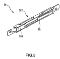
FIG. 5 is an antenna for WWAN of the present invention;
FIG. 6 is a back view of the integrated antenna according to the first embodiment of the present invention;
FIG. 7 is a back view of the integrated antenna according to the second embodiment of the present invention;
FIG. 8 is a schematic view of the integrated antenna according to the third embodiment of the present invention;
FIG. 9 is a schematic view of the integrated antenna according to the fourth embodiment of the present invention;
FIG. 10 is a stereogram of the integrated antenna according to the fifth embodiment of the present invention;
FIG. 11 is a front view of the integrated antenna according to the fifth embodiment of the present invention;
FIG. 12 is a WWAN antenna with a substrate according to the present invention;
FIG. 13 is a top view of the integrated antenna according to the sixth embodiment of the present invention (before the flexible printed circuit board is bent);
FIG. 14 is a stereogram of the integrated antenna according to the sixth embodiment of the present invention (after the flexible printed circuit board is bent); and
FIG. 15 is a WWAN antenna with a flexible printed circuit board according to the present invention (after the flexible printed circuit board is bent).
DETAILED DESCRIPTION OF THE INVENTION
Referring to FIGS. 2A and 2B, the arrangement structure of an integrated antenna applied to a notebook computer 2 according to the present invention is shown. The present invention can be used in various wireless electronic devices including, but not limited to, notebook computers. All the common electronic products such as personal digital assistant (PDA) can utilize the integrated antenna of the present invention to achieve the wireless communication. The notebook computer 2 has a screen 21 and a screen frame 22. The integrated antenna 3 of the present invention is disposed in the screen frame 22 of the notebook computer 2, and is connected to the control circuit of the notebook computer 2 by two coaxial wires 23 and 24, so as to transmit data through the integrated antenna 3.
The integrated antenna 3 has at least one fixing portion for fixing the integrated antenna 3 to the screen frame 22. In this embodiment, the fixing portion is two through-holes 35 (as shown in FIG. 3) for two screws 25 to fix the integrated antenna 3 to the screen frame 22 of the notebook computer 2 (as shown in FIG. 2B).
Referring to FIGS. 3, 4, and 6, schematic views of the integrated antenna 3 for WWAN and WLAN according to the first embodiment of the present invention are shown. Referring to FIGS. 3 and 4, the integrated antenna 3 comprises a ground metal plate 30, a coupled WWAN antenna 31, and a WLAN antenna 32. The coupled WWAN antenna 31 comprises a first radiating metal plate 311, a second radiating metal plate 312, and a third radiating metal plate 313. The first radiating metal plate 311 is a separate metal plate which is not connected to another metal plate and the ground metal plate 30. In this embodiment, the first radiating metal plate 311 is disposed at a predetermined position by a supporting element 33, and the supporting element 33 is an insulating element. In other applications, the first radiating metal plate 311 can also be disposed at the predetermined position by a plurality of supporting elements. The first radiating metal plate 311 is used to match with the second radiating metal plate 312 to induce a first resonance mode. The third radiating metal plate 313 is used to induce a second resonance mode. The frequency of the first resonance mode is in a range of 824 MHz to 960 MHz, and the frequency of the second resonance mode is in a range of 1575 MHz and 1710 MHz to 2170 MHz, wherein the frequency of 1575 MHz of the second resonance mode is applied to the Global Position System (GPS).
A distance D between the first radiating metal plate 311 and the second radiating metal plate 312 when inducing the first resonance mode is between 0.5 mm and 1.5 mm. When the distance D between the first radiating metal plate 311 and the second radiating metal plate 312 is between 0.5 mm and 1.0 mm, the induced frequency of the first resonance mode is in a range of 824 MHz to 894 MHz. When the distance D between the first radiating metal plate 311 and the second radiating metal plate 312 is between 1.0 mm and 1.5 mm, the induced frequency of the first resonance mode is in a range of 880 MHz to 960 MHz. The above-mentioned distance D can be determined in practice.
Therefore, referring to FIG. 2A, in practice, two integrated antennas are respectively disposed in the notebook computer 2, in which the frequency of the first resonance mode of one integrated antenna is in a range of 824 MHz to 894 MHz (D=0.5˜1.0 mm), and the frequency of the first resonance mode of the other integrated antenna is in a range of 880 MHz to 960 MHz (D=1.0˜1.5 mm).
The coupled WWAN antenna 31 further comprises a first connecting metal plate 314 and a second connecting metal plate 315 for respectively connecting the second radiating metal plate 312 and the third radiating metal plate 313 to the ground metal plate 30.
The WLAN antenna 32 is connected to the ground metal plate 30. The WLAN antenna 32 comprises a fourth radiating metal plate 321 and a fifth radiating metal plate 322 for respectively inducing a third resonance mode and a fourth resonance mode. The length of the fourth radiating metal plate 321 is less than that of the fifth radiating metal plate 322, so the frequency of the third resonance mode is higher than that of the fourth resonance mode. In this embodiment, the frequency of the third resonance mode is 5 GHz, and the frequency of the fourth resonance mode is 2.4 GHz.
Referring to FIGS. 4 and 6, the WLAN antenna 32 further comprises a third connecting metal plate 323 for connecting the fourth radiating metal plate 321 and the fifth radiating metal plate 322 to the ground metal plate 30. The fourth radiating metal plate 321 and the fifth radiating metal plate 322 extend in opposite directions, and are disposed approximately parallel with the ground metal plate 30 and separated for a distance, such that the WLAN antenna 32 is formed as an T shape. In addition, the integrated antenna 3 further comprises a gain metal plate 34 connected to the ground metal plate 30 for increasing the gain.
Therefore, the integrated antenna 3 of the present invention can be used in the frequency of WWAN (for example, in a range of 824 MHz to 960 MHz, in a range of 1575 MHz (the frequency of GPS) and 1710 MHz to 2170 MHz) and the frequency of WLAN (2.4 GHz or 5 GHz) at the same time.
Referring to FIGS. 3, 4, and 6 again, in the integrated antenna 3, the ground metal plate 30 is disposed on a bottom surface. The first connecting metal plate 314 and the second connecting metal plate 315 of the coupled WWAN antenna 31 extend from one side of the ground metal plate 30 and are disposed on a first side surface. The first radiating metal plate 311 of the coupled WWAN antenna 31 comprises a first portion 316, a second portion 317, and a third portion 318. The first portion 316 is disposed on the first side surface, and the second portion 317 is disposed on a top surface corresponding to the bottom surface. The third portion 318 is disposed on a second side surface corresponding to the first side surface. The second radiating metal plate 312 is disposed on the top surface. The third radiating metal plate 313 is disposed on the first side surface. The WLAN antenna 32 is disposed on the second side surface and the top surface, i.e., the third connecting metal plate 323 and the fourth radiating metal plate 321 are disposed on the second side surface, and the fifth radiating metal plate 322 extends from the second side surface to the top surface. The gain metal plate 34 is connected to the ground metal plate 30 and is disposed on the second side surface as the WLAN antenna 32. Therefore, the integrated antenna 3 is formed as approximately a shape of hollow cuboid with air as the medium.
Further, referring to FIGS. 2B and 4, the first portion 316 of the first radiating metal plate 311 has a first feed point F1 thereon, and the ground metal plate 30 has a first ground point G1 under the position relative to the first feed point F1. The first feed point F1 and the first ground point G1 are electrically connected to the coaxial wire 24. The joint between the third connecting metal plate 323 and the fourth radiating metal plate 321 and the fifth radiating metal plate 322 has a second feed point F2. The ground metal plate 30 has a second ground endpoint G2 under the position relative to the second feed point F2. The second feed point F2 and the second ground endpoint G2 are electrically connected to the coaxial wire 23. The coaxial wires 23 and 24 connect the integrated antenna 3 to the control circuit of the notebook computer 2 to receive wireless signals through the first feed point F1 and the second feed point F2 and transmit the signals to the control circuit of the notebook computer 2.
The integrated antenna 3 for WWAN and WLAN in the first embodiment of the present invention can only be used in WWAN by deleting the WLAN antenna, thus becoming an antenna 36 for WWAN, as shown in FIG. 5. The antenna 36 comprises a ground metal plate 361, a coupled WWAN antenna 362, and a supporting element 363, which have the same structure and arrangement as the above-mentioned ground metal plate 30, the coupled WWAN antenna 31, and the supporting element 33 of the integrated antenna 3 in the first embodiment of FIG. 3, and the details will not be described herein again.
Referring to FIG. 7, a schematic view of the integrated antenna 4 for WWAN and WLAN according to the second embodiment of the present invention is shown. The integrated antenna 4 comprises a ground metal plate 40, a coupled WWAN antenna 41, and a WLAN antenna 42. Unlike the integrated antenna 3 of the first embodiment, the WLAN antenna 42 of the second embodiment is not formed as an T shape. The third connecting metal plate 423 of the WLAN antenna 42 connects the fourth radiating metal plate 421 and the fifth radiating metal plate 422 to the ground metal plate 40. In addition, the fourth radiating metal plate 421 and the fifth radiating metal plate 422 extend in the same direction, and the fourth radiating metal plate 421 and the fifth radiating metal plate 422 are disposed in approximately parallel with the ground metal plate 40 and separated for a distance, so as to make the WLAN antenna 42 is formed as an F shape.
Referring to FIG. 8, a schematic view of the integrated antenna 5 for WWAN and WLAN according to the third embodiment of the present invention is shown. The integrated antenna 5 further comprises an auxiliary grounding element 51 connected to the ground metal plate 50 for providing proper grounding. In the fifth embodiment, the auxiliary grounding element 51 is an aluminum foil. In other applications, the auxiliary grounding element 51 can also be conductive foam or conductive glue.
Referring to FIG. 9, a schematic view of the integrated antenna 6 for WWAN and WLAN according to the fourth embodiment of the present invention is shown. The integrated antenna 6 further comprises a plurality of auxiliary grounding elements 61, 62. The auxiliary grounding elements 61, 62 are connected to the ground metal plate 60 and separated for a distance. The above-mentioned auxiliary grounding elements 61, 62 can be bent and folded, thus saving space to satisfy the requirements of customers and provide the preferred grounding effect and radiation effect. The ground metal plate 60 of the integrated antenna 6 further has a plurality of slots 601 which can be formed on two sides of the ground metal plate 60. The slots 601 can be used to adjust the characteristics of the antenna.
The integrated antenna of the present invention can be used in WWAN and WLAN at the same time, and has a size within 100×7×5. 8 mm3. Due to its small volume, the integrated antenna can be disposed in the wireless electronic device. In addition, the ground metal plate and the auxiliary grounding element of the antenna can be separately used to provide the grounding effect, and are selectively connected or not connected to the ground end of the wireless electronic device, and thus the integrated antenna of the present invention can be mounted on any place of the wireless electronic device, and also has stable electrical characteristics.
Referring to FIGS. 10 and 11, schematic views of the integrated antenna 7 for WWAN and WLAN according to the fifth embodiment of the present invention are shown. The integrated antenna 7 comprises a ground metal plate 70, a coupled WWAN antenna 71, a WLAN antenna 72, and a substrate 73. The arrangement of the ground metal plate 70, the coupled WWAN antenna 71, and the WLAN antenna 72 is the same as the arrangement of the ground metal plate 30, the coupled WWAN antenna 31 and the WLAN antenna 32 in the first embodiment, and the details will not be described herein again.
The ground metal plate 70 is disposed on a bottom surface of the substrate 73. The first connecting metal plate 714 and the second connecting metal plate 715 of the coupled WWAN antenna 71 extend from one side of the ground metal plate 70 and are disposed on a first side surface of the substrate 73. The first radiating metal plate 711 of the coupled WWAN antenna 71 comprises a first portion 716, a second portion 717, and a third portion 718. The first portion 716 is disposed on the first side surface, and the second portion 717 is disposed on a top surface of the substrate 73, in which the top surface is corresponding to the bottom surface. The third portion 718 is disposed on a second side surface of the substrate 73, in which the second side surface is corresponding to the first side surface. The second radiating metal plate 712 is disposed on the top surface. The third radiating metal plate 713 is disposed on the first side surface. The WLAN antenna 72 is disposed on the second side surface and the top surface, i.e., the third connecting metal plate 723 and the fourth radiating metal plate 721 are disposed on the second side surface, and the fifth radiating metal plate 722 extends from the second side surface to the top surface. The gain metal plate 74 is connected to the ground metal plate 70, and disposed on the same second side surface as the WLAN antenna 72. The substrate 70 can be a printed circuit board or a non-conductive solid material (such as plastic or wood). The substrate may also be used as a supporting element for supporting the first radiating metal plate 711.
The integrated antenna 7 of the fifth embodiment of the present invention utilizes the substrate 73 as the medium, which is different from the integrated antenna 3 of the first embodiment of the present invention using air as the medium. Therefore, the second embodiment, third embodiment and the fourth embodiment of the invention, can also utilize the substrate as the medium as in the fifth embodiment.
The integrated antenna 7 for WWAN and WLAN in the fifth embodiment of the present invention can only be used in WWAN by deleting the WLAN antenna, thus becoming an antenna 75 for WWAN, as shown in FIG. 12. The antenna 75 comprises a ground metal plate 751, a coupled WWAN antenna 752, and a substrate 753, which have the same structure and arrangement as the above-mentioned ground metal plate 70, the coupled WWAN antenna 71, and the substrate 73 of the integrated antenna 7 in the fifth embodiment of FIG. 10, and the details will not be described herein again.
Referring to FIG. 13, a schematic view of the integrated antenna 8 for WWAN and WLAN according to the sixth embodiment of the present invention is shown. The integrated antenna 8 comprises a ground metal plate 80, a coupled WWAN antenna 81, a WLAN antenna 82, and a flexible printed circuit board 83. The ground metal plate 80, the coupled WWAN antenna 81, and the WLAN antenna 82 are formed on a surface 831 of the flexible printed circuit board 83.
The first radiating metal plate 811 further comprises a first portion 816, a second portion 817, and a third portion 818. The ground metal plate 80 is disposed on a top of the flexible printed circuit board 83. A third connecting metal plate 823 extends downwards along a side of the ground metal plate 80. The WLAN antenna 82 is connected to the third connecting metal plate 823. A fourth connecting metal plate 841 extends downwards along the side of the ground metal plate 80. The gain metal plate 84 is connected to the fourth connecting metal plate 841 and is disposed in approximately parallel to the ground metal plate 80, and is separated for a distance.
A first connecting metal plate 814 and a second connecting metal plate 815 extend upwards from a bottom of the flexible printed circuit board 83, in which the bottom is corresponding to the top. The third radiating metal plate 813 is connected to the second connecting metal plate 815 and is disposed approximately parallel to the bottom, and separated for a distance. The second radiating metal plate 812 is connected to the first connecting metal plate 814, and is disposed approximately parallel with the third radiating metal plate 813, and is separated for a distance.
The first portion 816 of the first radiating metal plate 811 is disposed approximately at the same horizontal position as the third radiating metal plate 813. The second portion 817 of the first radiating metal plate 811 is disposed approximately at the same horizontal position as the second radiating metal plate 812 and is interposed between the second radiating metal plate 812 and the WLAN antenna 82. The third portion 818 of the first radiating metal plate 811 is disposed between the second radiating metal plate 812 and the ground metal plate 80 and is disposed approximately parallel with the second radiating metal plate 812, and is separated for a distance.
Referring to FIGS. 13 and 14, the flexible printed circuit board 83 is bent to be a cuboid, such that the ground metal plate 80 is disposed on a bottom surface of the cuboid. The first connecting metal plate 814 and the second connecting metal plate 815 of the coupled WWAN antenna 81 are electrically connected to one side of the ground metal plate 80 and are disposed on a first side surface of the cuboid. The first portion 816 of the coupled WWAN antenna 81 is disposed on the first side surface. The second portion 817 of the coupled WWAN antenna 81 is disposed on a top surface of the cuboid, in which the top surface is corresponding to the bottom surface. The third portion 818 of the coupled WWAN antenna 81 is disposed on a second side surface of the cuboid, in which the second side surface is corresponding to the first side surface. The second radiating metal plate 812 is disposed on the top surface. The third radiating metal plate 813 is disposed on the first side surface. The WLAN antenna 82 is disposed on the second side surface and the top surface, i.e., the third connecting metal plate 823 and the fourth radiating metal plate 821 are disposed on the second side surface, and the fifth radiating metal plate 822 extends from the second side surface to the top surface. The gain metal plate 84 is connected to the ground metal plate 80 and is disposed on the same second side surface as the WLAN antenna 82. The flexible printed circuit board 83 can also be used as a supporting element for supporting the first radiating metal plate 811.
After the flexible printed circuit board 83 is bent to be a cuboid, it still has the air therein. Therefore, the integrated antenna 8 of the sixth embodiment of the present invention uses the flexible printed circuit board 83 and air as the medium, which is different from the integrated antenna 3 of the first embodiment of the present invention using air as the medium. In addition, the second embodiment, the third embodiment, and the fourth embodiment of the present invention, can also use the flexible printed circuit board and air as the medium as in the sixth embodiment.
The integrated antenna 8 of the sixth embodiment can be used for WWAN and WLAN. In addition, the flexible printed circuit board 83 can be bent to form a determined shape by utilizing the bendable characteristic of the flexible printed circuit board 83, so as to be disposed in the wireless electronic device, such that the installation is flexible.
The integrated antenna 8 for WWAN and WLAN in the sixth embodiment of the present invention can only be used in WWAN by deleting the WLAN antenna, thus becoming an antenna 85 for WWAN, as shown in FIG. 15. The antenna 85 comprises a ground metal plate 851, a coupled WWAN antenna 852, and a flexible printed circuit board 853, which have the same structure and arrangement as the above-mentioned ground metal plate 80, the coupled WWAN antenna 81, and the flexible printed circuit board 83 of the integrated antenna 8 in the sixth embodiment of FIG. 14, and the details will not be described herein again.
While several embodiments of the present invention have been illustrated and described, various modifications and improvements can be made by those skilled in the art. The embodiment of the present invention is therefore described in an illustrative, but not restrictive, sense. It is intended that the present invention may not be limited to the particular forms as illustrated, and that all modifications which maintain the spirit and scope of the present invention are within the scope as defined in the appended claims.

Claims (35)

1. An integrated antenna for WWAN and WLAN, comprising:
a ground metal plate;
a coupled WWAN antenna, the coupled WWAN antenna comprising a first radiating metal plate, a second radiating metal plate, and a third radiating metal plate, the first radiating metal plate being a separate metal plate and used for matching with the second radiating metal plate to induce a first resonance mode, the third radiating metal plate used to induce a second resonance mode;
a WLAN antenna connected to the ground metal plate, the WLAN antenna comprising a fourth radiating metal plate and a fifth radiating metal plate for respectively inducing a third resonance mode and a fourth resonance mode;
an auxiliary grounding element electrically connected to the ground metal plate; and
at least one supporting element for supporting the first radiating metal plate.
2. The integrated antenna as claimed in claim 1, wherein the frequency of the first resonance mode is in a range of 824 MHz to 960 MHz, the frequency of the second resonance mode is in a range of 1575 MHz and 1710 MHz to 2170 MHz, the frequency of the third resonance mode is 5 GHz, and the frequency of the fourth resonance mode is 2.4 GHz.
3. The integrated antenna as claimed in claim 1, wherein the supporting element is an insulating element.
4. The integrated antenna as claimed in claim 1, wherein the coupled WWAN antenna further comprises a first connecting metal plate and a second connecting metal plate respectively used to connect the second radiating metal plate and the third radiating metal plate to the ground metal plate, in which the first radiating metal plate comprises a first portion, a second portion, and a third portion; and the WLAN antenna further comprises a third connecting metal plate used to connect the fourth radiating metal plate and the fifth radiating metal plate to the ground metal plate.
5. The integrated antenna as claimed in claim 4, wherein the fourth radiating metal plate and the fifth radiating metal plate extend in different opposite directions, so as to make the WLAN antenna is formed as an T shape; the WLAN antenna is disposed on a second side surface and a top surface of the integrated antenna; the third connecting metal plate and the fourth radiating metal plate are disposed on the second side surface; and the fifth radiating metal plate extends from the second side surface to the top surface.
6. The integrated antenna as claimed in claim 4, wherein the fourth radiating metal plate and the fifth radiating metal plate extend along the same direction and are disposed on the same side surface, so as to make the WLAN antenna is formed as an F shape.
7. The integrated antenna as claimed in claim 4, wherein the ground metal plate is disposed on a bottom surface of the integrated antenna; the first connecting metal plate and the second connecting metal plate of the coupled WWAN antenna extend from one side of the ground metal plate and are disposed on a first side surface of the integrated antenna; the first portion is disposed on the first side surface, the second portion is disposed on a top surface of the integrated antenna, the top surface is corresponding to the bottom surface, and the third portion is disposed on a second side surface of the integrated antenna, the second side surface is corresponding to the first side surface; and the second radiating metal plate is disposed on the top surface, and the third radiating metal plate is disposed on the first side surface.
8. The integrated antenna as claimed in claim 4, wherein the supporting element is a printed circuit board, and the ground metal plate is disposed on a bottom surface of the printed circuit board; the first connecting metal plate and the second connecting metal plate of the coupled WWAN antenna extend from one side of the ground metal plate and are disposed on a first side surface of the printed circuit board; the first portion is disposed on the first side surface, the second portion is disposed on a top surface of the printed circuit board, the top surface is corresponding to the bottom surface, and the third portion is disposed on a second side surface of the printed circuit board, the second side surface is corresponding to the first side surface; and the second radiating metal plate is disposed on the top surface, and the third radiating metal plate is disposed on the first side surface.
9. The integrated antenna as claimed in claim 4, wherein the supporting element is a non-conductive solid material, and the ground metal plate is disposed on a bottom surface of the non-conductive solid material; the first connecting metal plate and the second connecting metal plate of the coupled WWAN antenna extend from one side of the ground metal plate and are disposed on a first side surface of the non-conductive solid material; the first portion is disposed on the first side surface, the second portion is disposed on a top surface of the non-conductive solid material, the top surface is corresponding to the bottom surface, and the third portion is disposed on a second side surface of the non-conductive solid material, the second side surface is corresponding to the first side surface; and the second radiating metal plate is disposed on the top surface, and the third radiating metal plate is disposed on the first side surface.
10. The integrated antenna as claimed in claim 4, wherein the supporting element is a flexible printed circuit board, and the ground metal plate is disposed on a top of the flexible printed circuit board; the third connecting metal plate extends downwards along one side of the ground metal plate, and the WLAN antenna is connected to the third connecting metal plate; the first connecting metal plate and the second connecting metal plate extend upwards from a bottom of the flexible printed circuit board, the bottom is corresponding to the top; the third radiating metal plate is connected to the second connecting metal plate and is disposed parallel with the bottom and separated for a distance, and the second radiating metal plate is connected to the first connecting metal plate and is disposed parallel with the third radiating metal plate and separated for a distance; the first portion of the first radiating metal plate is disposed at the same horizontal position as the third radiating metal plate, the second portion of the first radiating metal plate is disposed at the same horizontal position as the second radiating metal plate and interposed between the second radiating metal plate and the WLAN antenna, and the third portion of the first radiating metal plate is disposed between the second radiating metal plate and the ground metal plate and parallel with the second radiating metal plate and separated for a distance.
11. The integrated antenna as claimed in claim 10, wherein the flexible printed circuit board is bent to be a cuboid, and the ground metal plate is disposed on a bottom surface of the cuboid; the first connecting metal plate and the second connecting metal plate of the coupled WWAN antenna are electrically connected to one side of the ground metal plate and disposed on a first side surface of the cuboid; the first portion is disposed on the first side surface, the second portion is disposed on a top surface of the cuboid, the top surface is corresponding to the bottom surface, and the third portion is disposed on a second side surface of the cuboid, the second side surface is corresponding to the first side surface; and the second radiating metal plate is disposed on the top surface, and the third radiating metal plate is disposed on the first side surface.
12. The integrated antenna as claimed in claim 1, wherein the distance between the first radiating metal plate and the second radiating metal plate is between 0.5 mm and 1.5 mm.
13. The integrated antenna as claimed in claim 12, wherein the distance between the first radiating metal plate and the second radiating metal plate is between 0.5 mm and 1.0 mm, and the induced frequency of the first resonance mode is in a range of 824 MHz to 894 MHz.
14. The integrated antenna as claimed in claim 12, wherein the distance between the first radiating metal plate and the second radiating metal plate is between 1.0 mm and 1.5 mm, and the induced frequency of the first resonance mode is in a range of 880 MHz to 960 MHz.
15. The integrated antenna as claimed in claim 1, further comprising a gain metal plate connected to the ground metal plate for increasing gain.
16. The integrated antenna as claimed in claim 1, wherein the auxiliary grounding element is aluminum foil.
17. The integrated antenna as claimed in claim 1, wherein the auxiliary grounding element is conductive glue.
18. The integrated antenna as claimed in claim 1, wherein the auxiliary grounding element is conductive foam.
19. The integrated antenna as claimed in claim 1, wherein the ground metal plate has at least one slot.
20. An antenna for WWAN, comprising:
a ground metal plate;
a coupled WWAN antenna, the coupled WWAN antenna comprising a first radiating metal plate, a second radiating metal plate, and a third radiating metal plate, the first radiating metal plate being a separate metal plate and used for matching with the second radiating metal plate to induce a first resonance mode, the third radiating metal plate used to induce a second resonance mode;
an auxiliary grounding element electrically connected to the ground metal plate; and
at least one supporting element for supporting the first radiating metal plate,
wherein the coupled WWAN antenna further comprises a first connecting metal plate and a second connecting metal plate respectively used to connect the second radiating metal plate and the third radiating metal plate to the ground metal plate; the first radiating metal plate comprises a first portion, a second portion, and a third portion.
21. The antenna as claimed in claim 20, wherein the frequency of the first resonance mode is in a range of 824 MHz to 960 MHz, and the frequency of the second resonance mode is in a range of 1575 MHz and 1710 MHz to 2170 MHz.
22. The antenna as claimed in claim 20, wherein the supporting element is an insulating element.
23. The antenna as claimed in claim 20, wherein the ground metal plate is disposed on a bottom surface of the antenna; the first connecting metal plate and the second connecting metal plate of the coupled WWAN antenna extend from one side of the ground metal plate and are disposed on a first side surface of the antenna; the first portion is disposed on the first side surface, the second portion is disposed on a top surface of the antenna, the top surface is corresponding to the bottom surface, and the third portion is disposed on a second side surface of the antenna, the second side surface is corresponding to the first side surface; the second radiating metal plate is disposed on the top surface, and the third radiating metal plate is disposed on the first side surface.
24. The antenna as claimed in claim 20, wherein the supporting element is a printed circuit board, and the ground metal plate is disposed on a bottom surface of the printed circuit board; the first connecting metal plate and the second connecting metal plate of the coupled WWAN antenna extend from one side of the ground metal plate and are disposed on a first side surface of the printed circuit board; the first portion is disposed on the first side surface, the second portion is disposed on a top surface of the printed circuit board, the top surface is corresponding to the bottom surface, and the third portion is disposed on a second side surface of the printed circuit board, the second side surface is corresponding to the first side surface; and the second radiating metal plate is disposed on the top surface, and the third radiating metal plate is disposed on the first side surface.
25. The antenna as claimed in claim 20, wherein the supporting element is a non-conductive solid material, and the ground metal plate is disposed on a bottom surface of the non-conductive solid material; the first connecting metal plate and the second connecting metal plate of the coupled WWAN antenna extend from one side of the ground metal plate and are disposed on a first side surface of the non-conductive solid material; the first portion is disposed on the first side surface, the second portion is disposed on a top surface of the non-conductive solid material, the top surface is corresponding to the bottom surface, and the third portion is disposed on a second side surface of the non-conductive solid material, the second side surface is corresponding to the first side surface; and the second radiating metal plate is disposed on the top surface, and the third radiating metal plate is disposed on the first side surface.
26. The antenna as claimed in claim 20, wherein the supporting element is a flexible printed circuit board, and the ground metal plate is disposed on a top of the flexible printed circuit board; the first connecting metal plate and the second connecting metal plate extend upwards from a bottom of the flexible printed circuit board, the bottom is corresponding to the top; the third radiating metal plate is connected to the second connecting metal plate and is disposed parallel with the bottom and separated for a distance; the second radiating metal plate is connected to the first connecting metal plate and is disposed parallel with the third radiating metal plate and separated for a distance; the first portion of the first radiating metal plate is disposed at the same horizontal position as the third radiating metal plate, the second portion of the first radiating metal plate is disposed at the same horizontal position as the second radiating metal plate, and the third portion of the first radiating metal plate is disposed between the second radiating metal plate and the ground metal plate and is disposed parallel with the second radiating metal plate and separated for a distance.
27. The antenna as claimed in claim 26, wherein the flexible printed circuit board is bent to be a cuboid, and the ground metal plate is disposed on a bottom surface of the cuboid; the first connecting metal plate and the second connecting metal plate of the coupled WWAN antenna are electrically connected to one side of the ground metal plate and are disposed on a first side surface of the cuboid; the first portion of the coupled WWAN antenna is disposed on the first side surface, the second portion of the coupled WWAN antenna is disposed on a top surface of the cuboid, the top surface is corresponding to the bottom surface, and the third portion of the coupled WWAN antenna is disposed on a second side surface of the cuboid, the second side surface is corresponding to the first side surface; and the second radiating metal plate is disposed on the top surface, and the third radiating metal plate is disposed on the first side surface.
28. The antenna as claimed in claim 20, wherein the distance between the first radiating metal plate and the second radiating metal plate is between 0.5 mm and 1.5 mm.
29. The antenna as claimed in claim 28, wherein the distance between the first radiating metal plate and the second radiating metal plate is 0.5 mm to 1.0 mm, and the induced frequency of the first resonance mode is in a range of 824 MHz to 894 MHz.
30. The antenna as claimed in claim 28, wherein the distance between the first radiating metal plate and the second radiating metal plate is between 1.0 mm and 1.5 mm, and the induced frequency of the first resonance mode is in a range of 880 MHz to 960 MHz.
31. The antenna as claimed in claim 20, further comprising a gain metal plate connected to the ground metal plate for increasing gain.
32. The antenna as claimed in claim 20, wherein the auxiliary grounding element is aluminum foil.
33. The antenna as claimed in claim 20, wherein the auxiliary grounding element is conductive glue.
34. The antenna as claimed in claim 20, wherein the auxiliary grounding element is conductive foam.
35. The antenna as claimed in claim 20, wherein the ground metal plate has at least one slot.
US11/437,686 2006-02-24 2006-05-22 Antenna for WWAN and integrated antenna for WWAN, GPS and WLAN Expired - Fee Related US7746288B2 (en)

Applications Claiming Priority (3)

Application Number Priority Date Filing Date Title
TW095106360 2006-02-24
TW95106360A 2006-02-24
TW095106360A TWI316775B (en) 2006-02-24 2006-02-24 Antenna for wwan and integrated antenna for wwan, gps and wlan

Publications (2)

Publication Number Publication Date
US20070200774A1 US20070200774A1 (en) 2007-08-30
US7746288B2 true US7746288B2 (en) 2010-06-29

Family

ID=38443488

Family Applications (1)

Application Number Title Priority Date Filing Date
US11/437,686 Expired - Fee Related US7746288B2 (en) 2006-02-24 2006-05-22 Antenna for WWAN and integrated antenna for WWAN, GPS and WLAN

Country Status (3)

Country Link
US (1) US7746288B2 (en)
JP (1) JP4287443B2 (en)
TW (1) TWI316775B (en)

Cited By (6)

* Cited by examiner, † Cited by third party
Publication number Priority date Publication date Assignee Title
US20080266185A1 (en) * 2007-04-27 2008-10-30 Hon Hai Precision Ind. Co., Ltd. Complex antenna
US20090115665A1 (en) * 2007-11-05 2009-05-07 Hon Hai Precision Ind. Co., Ltd. Multi-band antenna
US20100149043A1 (en) * 2008-12-15 2010-06-17 Tiao-Hsing Tsai Antenna device for wireless wide area network (wwan) and wireless local area network (wlan)
US20140097997A1 (en) * 2012-10-08 2014-04-10 Auden Techno.Corp. Metal frame antenna for a display
US20150280313A1 (en) * 2012-05-29 2015-10-01 Apple Inc. Structures for Shielding and Mounting Components in Electronic Devices
US10897087B2 (en) 2017-04-18 2021-01-19 Hewlett-Packard Development Company, L.P. Integrated slot antenna

Families Citing this family (6)

* Cited by examiner, † Cited by third party
Publication number Priority date Publication date Assignee Title
US7405704B1 (en) * 2007-01-30 2008-07-29 Cheng Uei Precision Industry Co., Ltd. Integrated multi-band antenna
US8106836B2 (en) * 2008-04-11 2012-01-31 Apple Inc. Hybrid antennas for electronic devices
TWI411166B (en) * 2008-04-14 2013-10-01 Hon Hai Prec Ind Co Ltd Complex antenna
US7586449B1 (en) * 2008-05-06 2009-09-08 Cheng Uei Precision Industry Co., Ltd. Antenna structure and method for manufacturing the antenna structure
CN107887688A (en) * 2016-09-29 2018-04-06 比亚迪股份有限公司 Mobile terminal and its antenna assembly
EP3555958A4 (en) * 2017-10-18 2020-11-25 Hewlett-Packard Development Company, L.P. Antennas in electronic devices

Citations (11)

* Cited by examiner, † Cited by third party
Publication number Priority date Publication date Assignee Title
JPS5978707A (en) 1982-10-29 1984-05-07 Hitachi Ltd Controlling method of rolling mill
TW227576B (en) 1992-01-27 1994-08-01 Wurth Paul Sa
US6339400B1 (en) 2000-06-21 2002-01-15 International Business Machines Corporation Integrated antenna for laptop applications
JP2002050924A (en) 2000-08-01 2002-02-15 Sansei Denki Kk Broad band incorporating antenna and its configuration method
JP2003008342A (en) 2001-06-20 2003-01-10 Sansei Denki Kk Dual band antenna and its configuration method
TW542416U (en) 2002-06-20 2003-07-11 Hon Hai Prec Ind Co Ltd Dual-band antenna
US20040014474A1 (en) 2002-06-20 2004-01-22 International Business Machines Corporation Wireless network connection switching management system and method
JP2004064282A (en) 2002-07-26 2004-02-26 Sansei Denki Kk Dual band antenna and configuration method thereof, and 3-band antenna
JP2004228640A (en) 2003-01-20 2004-08-12 Taiyo Yuden Co Ltd Dielectric antenna and mobile communication apparatus incorporating the same
US6876329B2 (en) * 2002-08-30 2005-04-05 Filtronic Lk Oy Adjustable planar antenna
US6982675B2 (en) 2003-12-13 2006-01-03 Information And Communications University Educational Foundation Internal multi-band antenna with multiple layers

Patent Citations (12)

* Cited by examiner, † Cited by third party
Publication number Priority date Publication date Assignee Title
JPS5978707A (en) 1982-10-29 1984-05-07 Hitachi Ltd Controlling method of rolling mill
TW227576B (en) 1992-01-27 1994-08-01 Wurth Paul Sa
US6339400B1 (en) 2000-06-21 2002-01-15 International Business Machines Corporation Integrated antenna for laptop applications
JP2002050924A (en) 2000-08-01 2002-02-15 Sansei Denki Kk Broad band incorporating antenna and its configuration method
JP2003008342A (en) 2001-06-20 2003-01-10 Sansei Denki Kk Dual band antenna and its configuration method
TW542416U (en) 2002-06-20 2003-07-11 Hon Hai Prec Ind Co Ltd Dual-band antenna
US20040014474A1 (en) 2002-06-20 2004-01-22 International Business Machines Corporation Wireless network connection switching management system and method
JP2004023768A (en) 2002-06-20 2004-01-22 Internatl Business Mach Corp <Ibm> Radio communication system, access point, mobile terminal detecting unit, base station, mobile terminal, method of radio communication change and instruction thereof, and program
JP2004064282A (en) 2002-07-26 2004-02-26 Sansei Denki Kk Dual band antenna and configuration method thereof, and 3-band antenna
US6876329B2 (en) * 2002-08-30 2005-04-05 Filtronic Lk Oy Adjustable planar antenna
JP2004228640A (en) 2003-01-20 2004-08-12 Taiyo Yuden Co Ltd Dielectric antenna and mobile communication apparatus incorporating the same
US6982675B2 (en) 2003-12-13 2006-01-03 Information And Communications University Educational Foundation Internal multi-band antenna with multiple layers

Non-Patent Citations (3)

* Cited by examiner, † Cited by third party
Title
Apr. 1, 2008 Office Action for Corresponding Japanese Patent Application No. 2006-143018.
Dec. 17, 2008 Office Action for corresponding Taiwan, R.O.C. Patent Application No. 095106360.
Feb. 24, 2009 Notice of Allowance for Corresponding Japanese Patent Application No. 2006-143018.

Cited By (11)

* Cited by examiner, † Cited by third party
Publication number Priority date Publication date Assignee Title
US20080266185A1 (en) * 2007-04-27 2008-10-30 Hon Hai Precision Ind. Co., Ltd. Complex antenna
US7868831B2 (en) * 2007-04-27 2011-01-11 Hon Hai Precision Ind. Co., Ltd. Complex antenna
US20090115665A1 (en) * 2007-11-05 2009-05-07 Hon Hai Precision Ind. Co., Ltd. Multi-band antenna
US8013793B2 (en) * 2007-11-05 2011-09-06 Hon Hai Precision Ind. Co., Ltd. Multi-band antenna
US20100149043A1 (en) * 2008-12-15 2010-06-17 Tiao-Hsing Tsai Antenna device for wireless wide area network (wwan) and wireless local area network (wlan)
US8022882B2 (en) * 2008-12-15 2011-09-20 Quanta Computer Inc. Antenna device for wireless wide area network (WWAN) and wireless local area network (WLAN)
US20150280313A1 (en) * 2012-05-29 2015-10-01 Apple Inc. Structures for Shielding and Mounting Components in Electronic Devices
US9263790B2 (en) * 2012-05-29 2016-02-16 Apple Inc. Structures for shielding and mounting components in electronic devices
US20140097997A1 (en) * 2012-10-08 2014-04-10 Auden Techno.Corp. Metal frame antenna for a display
US8907855B2 (en) * 2012-10-08 2014-12-09 Auden Techno Corp. Metal frame antenna for a display
US10897087B2 (en) 2017-04-18 2021-01-19 Hewlett-Packard Development Company, L.P. Integrated slot antenna

Also Published As

Publication number Publication date
TWI316775B (en) 2009-11-01
TW200733473A (en) 2007-09-01
JP2007228545A (en) 2007-09-06
JP4287443B2 (en) 2009-07-01
US20070200774A1 (en) 2007-08-30

Similar Documents

Publication Publication Date Title
US7746288B2 (en) Antenna for WWAN and integrated antenna for WWAN, GPS and WLAN
US7893877B2 (en) Antenna for WWAN and integrated antenna for WWAN, GPS and WLAN
US7345637B2 (en) Radio device and electronic apparatus
KR100638726B1 (en) Antenna module and electric apparatus using the same
US6853336B2 (en) Display device, computer terminal, and antenna
US6621464B1 (en) Dual-band dipole antenna
US6809689B1 (en) Multi-frequency antenna for a portable electronic apparatus
US7362286B2 (en) Dual band antenna device, wireless communication device and radio frequency chip using the same
US20060077108A1 (en) Computer with an embedded antenna
US20100079350A1 (en) Wwan printed circuit antenna with three monopole antennas disposed on a same plane
US20060119517A1 (en) Antenna
US7652633B2 (en) Antenna for GPS
JP2008193299A (en) Inverted f antenna
US20080261667A1 (en) Mobile terminal having an improved internal antenna
US20040201528A1 (en) Integrated antenna for portable computer
US7554498B1 (en) Antenna for WWAN
JP2004215132A (en) Radio equipment
US10530044B2 (en) Mobile device and antenna structure thereof
JP4235149B2 (en) Notebook computer
JP2004172912A (en) Multiband antenna
US10181638B2 (en) Radiofrequency antenna device
JP2002280817A (en) Small antenna with coaxial cable and information terminal using the same
US20080001839A1 (en) Multi-frequency antenna and related mobile device
JP2004064353A (en) Antenna component, antenna system, and communication apparatus
US20030210191A1 (en) Embedded antennas for a communications device

Legal Events

Date Code Title Description
AS Assignment

Owner name: YAGEO CORPORATION,TAIWAN

Free format text: ASSIGNMENT OF ASSIGNORS INTEREST;ASSIGNORS:WANG, CHI-YUEH;LEE, CHENG-HAN;MAI, CHING-CHIA;REEL/FRAME:017901/0535

Effective date: 20060501

Owner name: YAGEO CORPORATION, TAIWAN

Free format text: ASSIGNMENT OF ASSIGNORS INTEREST;ASSIGNORS:WANG, CHI-YUEH;LEE, CHENG-HAN;MAI, CHING-CHIA;REEL/FRAME:017901/0535

Effective date: 20060501

REMI Maintenance fee reminder mailed
LAPS Lapse for failure to pay maintenance fees
STCH Information on status: patent discontinuation

Free format text: PATENT EXPIRED DUE TO NONPAYMENT OF MAINTENANCE FEES UNDER 37 CFR 1.362

FP Lapsed due to failure to pay maintenance fee

Effective date: 20140629