US7747085B2 - Method of isomorphic singular manifold projection still/video imagery compression - Google Patents
Method of isomorphic singular manifold projection still/video imagery compression Download PDFInfo
- Publication number
- US7747085B2 US7747085B2 US09/745,363 US74536300A US7747085B2 US 7747085 B2 US7747085 B2 US 7747085B2 US 74536300 A US74536300 A US 74536300A US 7747085 B2 US7747085 B2 US 7747085B2
- Authority
- US
- United States
- Prior art keywords
- frame
- segment
- image
- compression
- polynomial
- Prior art date
- Legal status (The legal status is an assumption and is not a legal conclusion. Google has not performed a legal analysis and makes no representation as to the accuracy of the status listed.)
- Expired - Lifetime, expires
Links
Images


Classifications
-
- G—PHYSICS
- G06—COMPUTING; CALCULATING OR COUNTING
- G06T—IMAGE DATA PROCESSING OR GENERATION, IN GENERAL
- G06T9/00—Image coding
-
- G—PHYSICS
- G06—COMPUTING; CALCULATING OR COUNTING
- G06T—IMAGE DATA PROCESSING OR GENERATION, IN GENERAL
- G06T9/00—Image coding
- G06T9/001—Model-based coding, e.g. wire frame
-
- H—ELECTRICITY
- H04—ELECTRIC COMMUNICATION TECHNIQUE
- H04N—PICTORIAL COMMUNICATION, e.g. TELEVISION
- H04N19/00—Methods or arrangements for coding, decoding, compressing or decompressing digital video signals
- H04N19/10—Methods or arrangements for coding, decoding, compressing or decompressing digital video signals using adaptive coding
- H04N19/169—Methods or arrangements for coding, decoding, compressing or decompressing digital video signals using adaptive coding characterised by the coding unit, i.e. the structural portion or semantic portion of the video signal being the object or the subject of the adaptive coding
Definitions
- the present invention relates to image compression systems, and in particular relates to an image compression system which provides hypercompression.
- Image compression reduces the amount of data necessary to represent a digital image by eliminating spatial and/or temporal redundancies in the image information. Compression is necessary in order to efficiently store and transmit still and video image information. Without compression, most applications in which image information is stored and/or transmitted would be rendered impractical or impossible.
- Lossless compression reduces the amount of image data stored and transmitted without any information loss, i.e., without any loss in the quality of the image.
- Lossy compression reduces the amount of image data stored and transmitted with at least some information loss, i.e., with at least some loss of quality of the image.
- Lossy compression is performed with a view to meeting a given available storage and/or transmission capacity.
- external constraints for a given system may define a limited storage space available for storing the image information, or a limited bandwidth (data rate) available for transmitting the image information.
- Lossy compression sacrifices image quality in order to fit the image information within the constraints of the given available storage or transmission capacity. It follows that, in any given system, lossy compression would be unnecessary if sufficiently high compression ratios could be achieved, because a sufficiently high compression ratio would enable the image information to fit within the constraints of the given available storage or transmission capacity without information loss.
- Fractal compression though better than most, suffers from high transmission bandwidth requirements and slow coding algorithms.
- Another type of motion (video) image compression technique is the ITU-recommended H.261 standard for videophone/videoconferencing applications. It operates at integer multiples of 64 kbps and its segmentation and model based methodology splits an image into several regions of specific shapes, and then the contour and texture parameters representing the region boundaries and approximating the region pixels, respectively, are encoded.
- a basic difficulty with the segmentation and model-based approach is low image quality connected with the estimation of parameters in 3-D space in order to impart naturalness to the 3-D image.
- the shortcomings of this technique are obvious to those who have used videophone/videoconferencing applications with respect particularly to MPEG video compression.
- Standard MPEG video compression is accomplished by sending an “I frame” representing motion every fifteen frames regardless of video content.
- the introduction of I frames asynchronously into the video bitstream in the encoder is wasteful and introduces artifacts because there is no correlation between the I frames and the B and P frames of the video. This procedure results in wasted bandwidth.
- bandwidth is wasted because the I frame was essentially unnecessary yet, unfortunately, uses up significant bandwidth because of its full content.
- no I frame is inserted where there is a lot of motion in the video bitstream, such overwhelming and significant errors and artifacts are created that bandwidth is exceeded.
- the fourth public release of JPEG has only a 30:1 compression rate and the image has many artifacts due to a PSNR of less than 20 dB, while H320 has a 300:1 compression ratio for motion and still contains many still/motion image artifacts.
- Very high compression rates, high image quality, and low transmission bandwidth are critical to modem communications, including satellite communications, which require full-motion, high resolution, and the ability to preserve high-quality fidelity of digital image transmission within a small bandwidth communication channel (e.g. T1).
- state of the art compression techniques are not able to transmit high quality video in real-time on a band-limited communication channel.
- a compression technique for both still and moving pictures that has a very high compression rate, high image quality, and low transmission bandwidth and a very fast decompression algorithm would be of great benefit.
- a compression technique having the above characteristics and which preserves high frequency components as well as edge resolution would be particularly useful.
- ATR automatic target recognition
- Soft ATR is used to recognize general categories of objects such as tanks or planes or humans
- hard ATR is used to recognize specific types or models of objects within a particular category.
- Existing methods of both soft and hard ATR are Fourier transform-based. These methods are lacking in that Fourier analysis eliminates desired “soft edge” or contour information which is critical to human cognition. Improved methods are therefore needed to achieve more accurate recognition of general categories of objects by preserving critical “soft edge” information yet reducing the amount of data used to represent such objects and thereby greatly decrease processing time, increase compression rates, and preserve image quality.
- the present invention is based on Isomorphic Singular Manifold Projection (ISMP) or Catastrophe Manifold Projection (CMP).
- ISMP Isomorphic Singular Manifold Projection
- CMP Catastrophe Manifold Projection
- This method is based on Newtonian polynomial space and characterizes the images to be compressed with singular manifold representations called catastrophes.
- the singular manifold representations can be represented by polynomials which can be transformed into a few discrete numbers called “datery” (number data that represent the image) that significantly reduce information content. This leads to extremely high compression rates (CR) for both still and moving images while preserving critical information about the objects in the image.
- CR compression rates
- isomorphic mapping is utilized to map between the physical boundary of a 3-D surface and its 2-D plane.
- a projection can be represented as a normal photometric projection by adding the physical parameters, B (luminance) to generic geometric parameters (X,Y).
- B luminance
- X,Y generic geometric parameters
- This projection has a unique 3-D interpretation in the form of a “canonical singular manifold”. This manifold can be described by a simple polynomial and therefore compressed into a few discrete numbers resulting in hyper compression. In essence, any image is a highly correlated sequence of data.
- the present invention “kills” this correlation, and image information in the form of a digital continuum of pixels almost disappears.
- surfaces of objects may be represented in the form of simple polynomials that have single-valued (isomorphic) inverse reconstructions.
- these polynomials are chosen to represent the surfaces and are then reduced to compact tabulated normal form polynomials which comprise simple numbers, i.e., the datery, which can be represented with very few bits.
- This enables exceptionally high compression rates because the “sculpture” characteristics of the object are isomorphically represented in the form of simple polynomials having single-valued inverse reconstructions.
- Preservation of the “sculpture” and the soft edges or contours of the object is critical to human cognition of the image for both still and video image viewing and ATR.
- the compression technique of the present invention provides exact representation of 3-D projection edges and exact representation of all the peculiarities of moving (rotating, etc.) 3-D objects, based on a simple transition between still picture representation to moving pictures.
- the following steps may be followed to compress a still image using isomorphic singular manifold projections and highly compressed datery.
- the first step is to subdivide the original image, I 0 , into blocks of pixels, for example 16 ⁇ 16 or other sizes. These subdivisions of the image may be fixed in size or variable.
- the second step is to create a “canonical image” of each block by finding a match between one of fourteen canonical polynomials and the intensity distribution for each block or segment of pixels. The correct polynomial is chosen for each block by using standard merit functions.
- the third step is to create a model image, I M , or “sculpture” of the entire image by finding connections between neighboring local blocks or segments of the second step to smooth out intensity (and physical structure to some degree).
- the fourth step is to recapture and work on the delocalized high frequency content of the image, i.e., the “texture”. This is done by a subtraction of the model image, I M , generated during the third step from the original segmented image, I 0 , created during the first step. A preferred embodiment of this entire still image compression process will be discussed in detail below.
- Optimal compression of video and other media containing motion may be achieved in accordance with the present invention by inserting I frames based on video content as opposed to at fixed intervals (typically every 15 frames as in the in prior art motion estimation methods.
- the errors between standard “microblocks” or segments of the current frame and a predicted frame are not only sent to the decoder to reconstruct the current frame, but, in addition, are accumulated and used to determine the optimal insertion points for I frames based on video content.
- the accumulated error of all the microblocks for the current frame exceeds a predetermined threshold which itself is chosen based upon the type of video (action, documentary, nature, etc.), this indicates that the next subsequent frame after the particular frame having high accumulated error should be an I frame. Consequently, in accordance with the present invention, where the accumulated errors between the microblocks or segments of the current frame and the predicted frame exceed the threshold, the next subsequent frame is sent as an I frame which starts a new motion estimation sequence. Consequently, I frame insertion is content dependent which greatly improves the quality of the compressed video.
- the I frames inserted in the above compression technique may first be compressed using standard DCT based compression algorithms or the isomorphic singular manifold projection (ISMP) still image compression technique of the present invention for maximal compression.
- the compression techniques used are preferably MPEG compatible.
- compression ratios can be dynamically updated from frame to frame utilizing the accumulated error information.
- the compression ratio may be changed based on feedback from the receiver and, for instance, where the accumulated errors in motion estimation are high, the compression ratio may be decreased, thereby increasing bandwidth of the signal to be stored. If, on the other hand, the error is low, the compression ratio can be increased, thereby decreasing bandwidth of the signal to be stored.
- the present invention is a 3-D non-linear technique that produces high level descriptive image representation using polynomial terms that can be represented by a few discrete numbers or datery, it provides much higher image compression than MPEG (greater than 1000:1 versus 100:1 in MPEG), higher frame rate (up to 60 frames/sec versus 30 frames/sec in MPEG), and higher picture quality or peak signal to noise ratio (PSNR greater than 32 dB versus PSNR greater than 23 dB in MPEG). Consequently, the compression technique of the present invention can provide more video channels than MPEG for any given channel bandwidth, video frame rate, and picture quality.
- FIG. 1A illustrates a singularity called a “fold”
- FIG. 1B illustrates a singularity called a “cusp”
- FIG. 2A illustrates “Newton Diagram Space” and contains “monoms” and polynomials
- FIG. 2B illustrates the application of Newton diagram space in the context of ISMP Theory. Canonical and normal forms, etc.;
- FIG. 3A depicts a fold and FIG. 3B depicts tuck;
- FIG. 4A illustrates a reflection from a manifold
- FIG. 4B illustrates the reflection from a manifold depending upon angle ⁇
- FIG. 4C illustrates the projection on a display
- FIG. 5 illustrates a cylinder with constant luminance dependence
- FIGS. 7A and 7B illustrate a reflector of a group for three mirrors R 2 ;
- FIG. 8 illustrates a smooth curve projection, representing movement and a physical object, and a catastrophic frame change, and positionally zoom camera changes
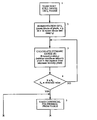
- FIG. 9 is a abbreviated flow chart of the inventive ISMP still image compression method.
- FIG. 10 is a detailed flow chart of the inventive ISMP compression method in accordance with the present invention.
- FIG. 11A illustrates an original image with an enlarged edge contour
- FIG. 11B shows a 2-D CCD image of the enlarged edge contour
- FIG. 11C illustrates a model surface of the original edge contour in accordance with the present invention
- FIG. 12 is an illustration of a segment of an original frame in accordance with the present invention.
- FIG. 13A-13C is an illustration of connecting segments of a frame in accordance with the present invention.
- FIG. 14A-14C illustrates subtracting I M from I 0 in accordance with the present invention
- FIG. 15 is a flow chart of the decoding process for ISMP compression in accordance with the present invention.
- FIG. 16 is a flow chart of the motion estimation process in accordance with the present invention.
- FIG. 17 is a circuit schematic of the hardware uses for motion estimation in accordance with the present invention.
- FIG. 18 is a flow chart of the error accumulation method of the present invention.
- FIG. 19 is a table showing the results of data communication with varying data rates in accordance with the present invention.
- Catastrophes are abrupt changes arising as a sudden response of a system to a smooth change in external conditions.
- catastrophe theory it is necessary to understand Whitney's singularity theory.
- mapping is said to be smooth if these functions are smooth (i.e., are differentiable a sufficient number of times, such as polynomials for example).
- Mappings of smooth surfaces onto a plane exist everywhere. Indeed, the majority of objects surrounding us are bounded by smooth surfaces.
- the visible contours of bodies are the projections of their bounding surfaces onto the retina of the eye. By examining the objects surrounding us, for instance, people's faces, the singularities of visible contours can be studied. Whitney observed that generically (for all cases bar some exceptional ones) only two kinds of singularities are encountered. All other singularities disintegrate under small movements of the body or of the direction of projection, while these two types are stable and persist after small deformations of the mapping.
- y 1 x 1 3 + x 1 ⁇ x 2
- y 2 x 2 with respect to spatial coordinates (x 1 , x 2 , y 1 ) and projects onto the horizontal plane (x 2 , y 1 ).
- Every nearby mapping has a similar singularity at an appropriate nearby point (that is, a singularity such that the deformed mapping, in suitable coordinates in a neighborhood of the point mentioned, is described by the same formulas as those describing the original mapping in a neighborhood of the original points).
- Whitney also proved that every singularity of a smooth mapping of a surface onto a plane, after an appropriate small perturbation, splits into folds and cusps.
- the visible contours of generic smooth bodies have cusps at points where the projections have cusp singularities, and they have no other singularities. These cusps can be found in the lines of every face or object.
- CMP Catastrophic Manifold Projection
- ISMP Isomorphic Singular Manifold Projection
- Critical Point For a function depending on n variables ( ⁇ R n or n-dimensional magnified), a critical point is called nondegenerate if its second differential is a nondegenerate quadratic form. In other words, for this point, only one row of the Jacobian is equal to zero.
- Morse lemma In the neighborhood of a nondegenerate critical point, a function may be reduced to its quadratic part, i.e., it may be written into the normal form
- u ⁇ 1 2 - ... - ⁇ k 2 + ⁇ k + 1 2 + ⁇ ( 1 ) for a certain local coordinate system ( ⁇ 1 , . . . , ⁇ n ).
- Thom's lemma provides a basis for an application mapping algorithm for any surfaces that can be mapped on an image plane.
- Thom's form can be used as a nondegenerate function for image approximation, but using singularities analysis allows extraction of the most important information from an image.
- FIG. 3A depicts a fold and FIG. 3B depicts a cusp.
- 3-D objects presented in the form of 2-D images, are projections of the following types of objects:
- Formation of an image can be described as light reflection from a general surface. It may be an actual radiation surface (light source, transparent surface, or semi-transparent surface) or it may be an opaque reflected surface.
- the reflection is the highest in the specular direction, and it is monotonically reduced, with an increase of the reflection direction separation from the specular direction, as shown in FIG. 4 .
- This photometric projection approach can be derived from Thom's lemma and the Arnold theorem.
- CMP Catastrophic Manifold Projection
- image formation can be presented as differential mapping from 4-D space (x, y, z, B; where x, y, z are real 3-D space coordinates of a point and B is the luminance of that point) to the image plane (u, v, w), where u and v are coordinates of a pixel and w is a color (or gray scale level) of the pixel.
- the result of mapping the manifold with internal curvilinear ( ⁇ , ⁇ ) coordinates will be a 3-D surface (u, v, w); where u, v are coordinates of the point into the plane and w is the luminance of the point.
- Function (10C) is expanded into infinite Taylor series, in the vicinity of ⁇ 0 , ⁇ 0 , and B 0 , in the form:
- a luminance physical coordinate does not introduce new singularities, and, because g depends only on geometrical coordinates ( ⁇ , ⁇ ) (belonging to 3-D space manifold), all previous results of the Whitney-Thom-Arnold theory apply in this new geometrical/physical (“geophysical”) 4-D space. (See Table 1.)
- the Jacobian is considered, transforming coordinates ( ⁇ , ⁇ , B) into (u, v, w) in the form:
- the first row of the matrix is not equal to 0, except
- w ⁇ ( ⁇ , B ) CB + f ⁇ ( ⁇ 0 , B 0 ) + ⁇ f ⁇ u ⁇ ⁇ u ⁇ ⁇ ⁇ ( ⁇ - ⁇ 0 ) + ⁇ ... ( 22 )
- H 3 is a group of symmetry of the icosahedron.
- H 3 has special properties, as described below.
- the points of a plane that have an equal number of reflections (12 in FIG. 4A ) belong to one (regular) orbit. Points located on the mirrors belong to another orbit.
- a set of all irregular orbits in a factor space is a discriminant (i.e., the manifold in a factor space).
- the plane in 3-D space can be represented, as in FIG. 4 , as a plane with coordinates z 1 , z 2 , z 3 .
- z i z j
- Orbits in this context constitute a set of numbers ⁇ z 1 , z 2 , z 3 ⁇ (with all permutations generated by reflections), with the additional condition of Eq. (23).
- Each point (a, b) of this space corresponds to a cubic polynomial and its roots. If some of the roots are equal, that means we have received irregular orbits.
- Catastrophe or alternatively isomorphic singular manifold as used in this patent designates a mathematical object that describes the shape of 3-D object boundaries in polynomial form.
- the use of “catastrophe” theory for compression makes the present invention unlike all other compression methods because it helps to transmit information about 3-D object boundaries without loss, preserving the features of the object most valuable to human cognition, but with very high compression rate.
- By applying the present invention to still image compression a 300:1 still image compression ratio with practically invisible artifacts (PSNR equal 32 dB) and a 4,000:1 full motion image compression ratio with fully developed natural motion and good image quality, is obtained.
- the still image compression and related video compression technique of the present invention is extremely beneficial because, unlike other state of the art compression techniques, major information losses do not occur from compression at 3-D object boundaries (edges) that require both high dynamic range and high resolution (i.e., both high spatial and high vertical: “Lebesque” resolution). In these edges there is a vast amount of information necessary for many processing operations vital to a quality image and human cognition.
- the compression technique of the present invention unlike other compression methods, preserves intact all “soft-” edge information without data loss.
- the present inventors have coined the term lossless-on-the-edges (LOTE) compression.
- LOTE compression is possible because of the fully isomorphic projection between the 3-D object boundary vicinity and its 2-D projection on the screen.
- the retina of the human eye contains millions of receptor cells, arranged in a mosaic-like pattern in the retinal layer.
- the receptor cells are cones and rods. These cones and rods provide the starting point for two separate but interacting visual systems within the human eye.
- Cone vision is specialized for high acuity and for perception of color.
- Rod vision is specialized for sensitivity and the ability to distinguish color (i.e., a person can make out the general shape of the objects, but not their colors or small details [8] ).
- the main purpose of human vision is not to detect simple presence or absence of light, but rather to detect and identify objects. Objects are defined principally by their contours.
- the visual system registers a greater difference in brightness between adjacent visual images. Faithfully recording the actual physical difference in light intensity.
- This still image compression performance can be transformed into analogous video image compression through the typical 10:1 factor for state of the art video image compression. Therefore, the inventive technique can be applied not only to high resolution digital video/still image transmission, but also to multi-media presentation, high quality video conferencing, video servers, and the storage of large amounts of video information.
- Video compression is a four dimensional (4-D) problem where the goal is to remove spatial and temporal redundancy from the stream of video information.
- 4-D four dimensional
- In video there are scenes containing an object that continuously changes without jumps and has no edges, and, on the other hand, there are also scenes where there are cuts which are big jumps in the temporal domain or big jumps in the spatial domain (such as “edges”). These abrupt changes or jumps can be described as “catastrophes.”
- Using catastrophe theory these behaviors can be described by one or more elemental catastrophes. Each of these elemental catastrophes describes a particular type of abrupt change in the temporal or spatial domains.
- categorizing catastrophes in 4-D space is even less established than catastrophe theory in general which is relatively unknown.
- 4-D space is far less understood than 3-D space but, similarities between them can be expected and can use projection-type mapping can be used, but in temporal space.
- One solution is to use spatial catastrophes along with temporal catastrophes.
- a fourth “geometrical” coordinate, time leading to time-space (4-D) is preferably added.
- inventive isomorphic singular manifold projection (ISMP) methodology five-dimensional (5-D) geometro-physical space (x, y, z, t, B), where B is brightness, or luminance, is obtained.
- This 4-D time-space (x, y, z, t) plus physical coordinate, B can be split into 4-D geometro-physical space, and time (t) and treated separately except in the case of relativistic velocities.
- the 5-D space can be analyzed by Poincare group formalism.
- temporal singularities may be described in the time-luminance (t, B) domain only.
- the time-luminance singularities may interfere with spatial singularities (previously discussed).
- each block of the image is represented by a single time-variable value.
- FIG. 8 there are only two possible singularities describing any type of mapping including smooth curve projection designated ( 1 ) shown in FIG. 8 where ⁇ B> is the average B-value characterizing a frame as a total structure (the smooth projection shown in FIG. 8 represents movement of a physical object. Item ( 2 ) in FIG. 8 representing a catastrophic frame change, and item ( 3 ) representing position/tilt/zoom camera changes.
- the critical ⁇ B >-parameter may be, for example, an average block-to-block error (e.g. mean square error).
- temporal catastrophic formalisms can be applied to MPEG hypercompression by replacing the average error parameters by integrated luminance-changes.
- Images are 3-D distributions of intensity. Abrupt changes in intensity occurring over small changes in x, y may be treated as catastrophic changes.
- the inventors have modified catastrophe theory to fit images and to solve the problems of image and video compression.
- the inventors have introduced a physical coordinate, B (luminance) into conventional geometrical coordinates to create “geometro-physical” surfaces.
- the table below identifies the fourteen polynomials or germs.
- Type f(x, y) Type f(x, y) 1 x (without singularities) 8 x 4 + x 2 y + xy 2 2 x 2 (fold) 9, 10 x 5 ⁇ x 3 y + xy 3 x 3 + xy (Whitney's tuck) 11, 12 x 3 ⁇ xy 4 4, 5 x 3 + xy 2 (3/1 type curve) 13 x 4 + x 2 y + xy 3 6 x 3 + xy 3 (9/2 type curve) 14 x 5 + xy 7 x 4 + xy (4/3 type curve)
- SSRNF Spectral Series for Reduction to the Normal Form
- Catastrophe theory has not been before used for studying image intensity because the number of coefficients necessary to satisfactorily describe an image using standard polynomials is simply too large and can exceed the number of pixels present in an image. Obviously, such an analysis is not worthwhile because the data that need to be handled are larger than the number of pixels, itself a very large number.
- the inventors have discovered that it is possible to remove many of the details or “texture” in images, leaving the important “sculpture” of the image, prior to characterizing the image with polynomials, to significantly decrease the number of coefficients in the polynomials that describe the different edge transitions in mapping and 3-D space.
- Step 1 involves segmenting the original image into blocks of pixels, for example 16 ⁇ 16.
- Step 2 is to create a model surface for each segment or block corresponding to the original image so that there is isomorphism between the original image and the polynomial surface in accordance with Arnold's Theorem. More particularly this may involve calculating the equation F modelled for each block or segment by substituting for variables in canonical polynomials. (See Steps 3 - 7 of detailed flow chart which follows). This step inherently eliminates texture of the image and emphasizes the “sculpture” characteristics.
- Step 3 is to optimize each model segment.
- Step 4 is to find connections between adjacent segments to create an entire image i.e., a model image of the entire frame. (See Steps 14 - 18 of the detailed flow chart). This yields an entire image that has only the “sculpture” characteristics of the original image and eliminates texture.
- Step 5 is to calculate the peak signal to nose ratio PSNR over the entire image and where the PSNR of the entire image is less than a threshold, the difference between the original image and the modelled image is calculated. This step recreates the texture information of the original image that was lost during the process.
- Step 6 is to use standard lossy compression on the texture portion of the data and then to combine the texture and datery and apply standard lossless compression to that combined data. (See Steps 22 - 24 of the detailed flow chart).
- the original image I o is segmented into blocks of pixels of any desired size such as, for example, 16 ⁇ 16 square blocks.
- the original image is seen in FIG. 11A .
- Any segment size may be used as desired.
- These segments or blocks of pixels are designated i o .
- Step 3 is the first step involving segment by segment operation on each i o using matrix representation of each segment.
- Step 4 compares the Dynamic Range R to R o which is a threshold determined from trial and error.
- the threshold R o is chosen so as to eliminate unnecessary compression such as compression of background scenes. In this regard, if the value R is very small and less than R o , the image is most likely background and the compression technique of the present invention is not needed. In this case, the process is started over again between steps 2 and 3 and another segment or block is operated on. If R is greater than or equal to R o then the subsequent steps involved in choosing a canonical polynomial from the table and creating a model polynomial by solving its coefficients are then performed. This set of steps now generally described involves choosing the polynomial from the table which best matches each particular segment or block.
- step 5 a first canonical polynomial from the table is taken.
- step 6 substitutions for variables in the canonical polynomials are found. It is possible to apply (1) a nonhomogeneous linear transformation (shift of coordinates), (2) a homogeneous linear transformation (rotation of axis) or (3) a nonhomogeneous nonlinear transformation. For example, if the canonical polynomial
- x 1 ( y 1 + a 1 ⁇ y 1 2 + ⁇ ... ⁇ ⁇ a n ⁇ y n 2 )
- x 2 ( y 2 + b 1 ⁇ y 2 2 + ⁇ ... ⁇ ⁇ b n ⁇ y n 2 )
- the modeled surface is created by substituting the coordinates of each pixel in the original segment or block into the equation f model .
- a modelled surface is seen in FIG. 11C .
- This creates a matrix containing the values f m(1.1) , f m(1.2) . . . as seen in FIG. 12 .
- this matrix is created by substituting the coordinate of the pixel 1 , 1 from the original segment into the equation f model to generate the element f m(1.1) in the modeled matrix.
- the coordinate of the pixel 1 , 2 from the original segment is substituted into the equation f model to generate value f m(1.2) which goes in the 1 , 2 pixel location of the modeled surface. This is done for each pixel position of the original segment to create a corresponding modeled matrix using the equation f model .
- Q is calculated by determining the difference between the original and modeled segments, pixel by pixel, using the equation:
- Q is calculated by subtracting corresponding pixels from the i o segment (the original segment) from the i m (the modeled segment) and squaring this subtraction and summing up all these squares.
- Q is compared to a predetermined threshold Q o based on image quality desired.
- Q should be less than Q o because the point of the step 8 is to minimize the sum of the differences between the analogous pixels in the original and modeled frames so as to generate a modeled surface that is as close as possible to the original surface. If Q is greater than Q o , the procedure loops back up to step 6 where new coefficients are tried in the same polynomial. Then steps 7 , 8 , and 9 are repeated, and if Q is less than Q o with that new set of coefficients, then the process continues into step 10 where that Q and the coefficients that produced the lowest Q for that polynomial are stored.
- step 10 After storage at step 10 , the process loops back up to step 5 if all polynomials have not yet been tested where the next canonical polynomial from the library is chosen and tested and solved for coefficients which produce the lowest Q for that next polynomial. Hence, steps 6 , 7 , 8 , and 9 are repeated for that next polynomial until coefficients are found which produce the lowest Q for that polynomial. At step 10 , the Q and the coefficients for that next polynomial are stored. This process of steps 5 , 6 , 7 , 8 , 9 , and 10 is repeated for each polynomial in the library. After each polynomial in the library is tested for the segment under test, the process moves to step 11 .
- step 11 the polynomial having the lowest Q of the polynomials tested for that segment is chosen. That polynomial is transferred to step 12 .
- step 12 all coefficients for the chosen polynomial (the one having the lowest Q of all the polynomials tested for that segment) are stored. These coefficients are coefficients of the equation f model which describes the modeled surface.
- step 12 the next set of operations involves segment by segment operation working only with the polynomials and their coefficients whereas the above steps 5 - 12 worked with the matrix representation of each segment. Because only the polynomials and their coefficients are worked with in the next set of operations, a significant amount of compression has taken place because the data representing the surface is far less voluminous than when a matrix representation of the segments is worked with. The data is simply coefficients of polynomials which can be called “datery”.
- a connection is found between adjacent or neighboring segments by extending the surface of a first segment into a second segment and finding differences between the extended surface and the second segment surface. Specifically, this is done by finding the average distance “q” between the surface which extends from the first segment into the second segment and the surface of the second segment using standard methods. If the average distance “q” is smaller than a threshold value q o , the surface of the second segment is approximated by the extended surface. In other words, if the distance q is smaller than the threshold value q o , the second segment surface is thrown out because it can be approximated satisfactorily by substituting the extended surface in its place. If the average distance q is greater than the threshold value q o , a connection needs to be found between the extended surface and the surface of the second segment.
- the average distance q is checked to determine whether it is less than the threshold value q o . If it is, then the connections between the adjacent or neighboring segments which can be plotted as a graph, as seen in FIG. 13 , are stored on a segment by segment basis. In other words, as seen in FIG. 13 , the surfaces which extend from, say, a surface in segment “ 9 ” into adjacent or neighboring segments (8, 10, 14 and 15), if any, are stored in the polynomial for segment 9 (earlier calculated and then stored at step 12 ) which then represents that graph of connections between segment 9 and segment 8 , 10 , 14 and 15 .
- segment 9 the polynomial that was calculated and stored for the segment in question, here segment 9 , is modified so that it now extends into adjacent segments 8 , 10 , 14 , and 15 and represents the surfaces in those segments.
- the polynomials for segments 8 , 9 , 10 , 14 will be substituted with the new bigger scale polynomial obtained from 9 .
- splines are calculated from the segment with adjacent segments using standard spline equations which need not be detailed here.
- a model image i m is created of the entire frame by creating a table of all segments for that frame using the information calculated for each segment in the above steps.
- the creation of this table representing the entire frame from its numerous segments is analogous to step 7 where a modeled segment was created by substituting the pixel coordinates from the original segment into the f model polynomial to get a matrix describing the modeled surface.
- a modeled frame is created from modeled segments.
- step 19 the peak signal to noise ratio (PSNR) is calculated over the entire image using the equation:
- PSNR 10 ⁇ ⁇ log 10 ⁇ ( number ⁇ ⁇ of ⁇ ⁇ gray ⁇ ⁇ scale ⁇ ⁇ levels ) 2
- h and v are number of pixels in horizontal and vertical directions respectively for the entire frame image.
- the Q values for each of the segments were stored at step 10 above and may be retrieved for this purpose.
- the PSNR of the entire frame is compared to a threshold P o . If PSNR is less than P o , then no further processing according to the present invention need be accomplished and processing can continue at step 24 where a standard lossless compression such as Hoffman encoding and run-length encoding are used to further compress the frame data. The compressed data is then sent to storage or a communication link.
- a standard lossless compression such as Hoffman encoding and run-length encoding are used to further compress the frame data.
- step 21 the difference between the original frame I o and the modeled frame I m is found by subtracting each pixel in I m (which was created at step 18 ) from the corresponding pixels in I o and a new frame I d is created (see FIG. 14 ) where each pixel in that frame has as its value the difference between the corresponding pixels in the frame I o and the frame I m .
- the frame I d therefore corresponds to the high frequency components, such as edge information which typically is lost in conventional compression techniques. This “texture” information containing high frequency components and edge information is then compressed separately at step 22 .
- step 22 standard lossy texture compression of the newly created frame I d is performed by using standard methods such as DCT, wavelet, and fractal methods.
- standard additional lossless compression is also performed.
- the output of step 22 is I d ′ which then is fed into step 23 .
- step 23 the I m frame is stored and the I d ′ frame is stored. This concludes the compression of the still frame or I o frame.
- the polynomial surface image is highly compressed because it is stored and transmitted as a complex algorithm (polynomial) rather than as a matrix representation. Additionally, the edge contour image I d is separated from the polynomial surface, as a by-product of characterizing the original image by a canonical polynomial and contains the high frequency and edge components and is itself compressed.
- the still image decoding process will now be described as seen in the flow chart of FIG. 15 .
- the input to the still image decoding process will be either just the whole frame I m in the case where the PSNR of the whole frame at step 20 was not less than threshold P o or the whole frame I m plus I d ′ where the PSNR of the whole frame at step 20 was less than P o and the differences between the original I o frame and the modeled frame I m were calculated to create new frame I d holding the textured or high frequency and edge information.
- the first step in decoding is step 1 which decodes the lossless compression data from the encoder which was compressed at step 24 .
- frame I m is separated from the other data in the bitstream.
- the first graph or segment which was stored at step 16 on a segment by segment basis is taken.
- step 4 whether the segment belongs to a graph (i.e., has connections to adjacent segments) or is an isolated segment (i.e., has no connections to neighboring segments) is tested. If the segment does belong to a graph, then at step 5 , a segment i m is constructed for each graph (analogous to the creation of the modeled matrix surface in step 7 of the encoding process) using the polynomial that was stored for that graph at step 16 of the encoding process.
- step 4 If the segment does not belong to a graph, then after step 4 the process skips step 5 and continues with step 6 .
- step 6 the separate graphs using standard splines are connected.
- those segments from steps 14 , 15 , and 17 which were connected by splines will be reconnected here. (Recall that it was these segments for which the extended surface of another adjacent segment did not satisfactorily characterize the surface of these segments and therefore a spline equation had to be used.)
- step 7 From step 5 where a segment i m for each graph was reconstructed, and from step 6 where separate graphs were connected using standard splines, the process continues at step 7 .
- the frame I m is constructed using segments from step 5 (in the same way as the frame I m was constructed in the encoding process at step 18 and also similar to how an individual segment or modeled surface or modeled segment was created at step 7 in the encoding process.)
- step 8 the presence of a I d ′ frame for or in conjunction with the frame I m is tested. If there is no frame I d ′, then the process is finished and the still image is fully decoded for that frame. If on the other hand there is a frame I d ′ in conjunction with the frame i m , then the process continues to step 9 .
- step 9 the frame I d ′ is decompressed.
- frame I d ′ is created from the combination of frame I m from step 7 of the decoding process and frame I d ′ from step 9 of the decoding process. After the frame I o ′ is created, the process is finished and the still image is fully decoded.
- the inventive compression technique for still images can be incorporated into standard MPEG compression to enhance video compression through spatial hypercompression of each I frame inserted into the video bitstream.
- a novel motion estimation technique is employed which provides significantly greater compression due to temporal compression.
- I frames are inserted according to video content. This is done by accumulating the error or difference between all corresponding microblocks or segments of the current frame and the predicted frame and comparing that accumulated error or difference to a threshold to determine whether the next subsequent frame sent should be an I frame. If the error or difference is large (i.e., when motion error is high), the I frame is sent. If the error or difference is small, the I frame is not sent and the frame sequence is unaltered.
- the present invention analyzes the errors between the I frame and the B and P frames into which it will be inserted to decide whether to insert the I frame at that point or not. Consequently, the present invention significantly increases the overall image compression ratio, while offering a simultaneous benefit of increased image quality.
- the technique of the present invention for video compression the distances between I frames are enlarged, which leads to better motion estimation and prediction.
- the video compression technique of the present invention may be used with both I frames compressed using the still ISMP compression encoding process of the present invention or standard I frame compression techniques.
- the most significant compression will occur if both the ISMP compression encoding process of the present invention and the motion estimation process of the present invention are used. It is worth noting that in existing systems, a reasonable quality video can be produced only if I frame compression is not higher than 20:1 to 40:1. With the present invention I frame compression of 300:1 is achieved.
- the following table illustrates the improvement over standard compression of the inventive technique of fixed separation of I frames compressed with the inventive CT algorithm used in conjunction with the inventive variable separation of I frames compressed with the CT algorithm.
- Motion estimation is important to compression because many frames in full motion video are temporally correlated, e.g., a moving object on a solid background such as an image of a moving car will have high similarity from frame to frame.
- Efficient compression can be achieved if each component or block of the current frame to be encoded is represented by its difference with the most similar component, called the predictor, in the previous frame and by a vector expressing the relative position of the two blocks from the current frame to the predicted frame.
- the original block can be reconstructed from the difference, the motion vector, and the previous frame.
- the frame to be compensated can be partitioned into microblocks which are processed individually. In a current frame, microblocks of pixels, for example 8 ⁇ 8, are selected and the search for the closest match in the previous frame is performed.
- the mean absolute error is the most often used because of the good trade off between complexity and efficiency.
- the search for a match in the previous frame is performed in a, for example, 16 ⁇ 16 pixels window for an 8 ⁇ 8 reference or microblock. A total of, for example, 81 candidate blocks may be compared for the closest match. Larger search windows are possible using larger blocks 8 ⁇ 32 or 16 ⁇ 16 where the search window is 15 pixels larger in each direction leading to 256 candidate blocks and as many motion vectors to be compared for the closest match.
- the standard methods provide that the error between a microblock in the current frame and the corresponding microblock in the predicted frame are compared and the error or difference between them is determined. This is done on a microblock by microblock basis until all microblocks in the current frame are compared to all the microblocks in the predicted frame. In the standard process these differences are sent to the decoder real time to be used by the decoder to reconstruct the original block from the difference, the motion vector, and the previous frame. The error information is not used in any other way.
- the error or difference calculated between microblocks in the current frame and the predicted frame are accumulated or stored and each time an error is calculated between a microblock in the current frame and the corresponding microblock in the predicted frame that error is accumulated to the existing error for that frame.
- This methodology is MPEG compatible and yields extremely high quality video images not possible with state of the art motion estimators.
- the accumulated error is used to advantage by comparing it to a threshold E 0 which is preset depending upon the content or type of the video such as action, documentary, or nature.
- E 0 for a particular current frame is exceeded by the accumulated error, this means that there is a significant change in the scene which warrants sending an entire new I frame. Consequently, an entire new I frame is compressed and sent, and the motion estimation sequence begins again with that new I frame. If E 0 is not exceeded by the accumulated error, then the differences between the current frame and the predicted frame are sent as usual and this process continues until E 0 is exceeded and the motion estimation sequence is begun again with the sending of a new I frame.
- the motion estimation process is now described in detail.
- This frame may be the first frame of the video in which case it is an I frame or may be a subsequent frame.
- F 0 was compressed by standard DCT methods, the left branch of the flow chart of FIG. 8 is followed. If F 0 was compressed using the inventive ISMP algorithm, the right branch of the flow chart in FIG. 8 is followed.
- step 3 involves standard segmenting of the F 0 frame into search blocks having subblocks called microblocks and defining motion vectors which are used to predict the third subsequent frame after F 0 . This is accomplished using standard techniques well known in the art.
- step 4 the error or difference between each microblock in F 0 and the corresponding microblock in the predicted third subsequent frame is defined for all microblocks in F 0 .
- the inventive motion estimation processed diverges from standard techniques.
- the motion estimation technique of the present invention is especially valuable because it will, dependent upon the content of the video, insert or send an I frame to the decoder when the content of the video warrants it. In this way, a high quality image is maintained.
- step 5 This is accomplished in the present invention by, as seen at step 5 , accumulating the error between corresponding microblocks in the F 0 and the predicted third subsequent frame as each error is defined in step 4 for each microblock of F 0 .
- step 6 is optional and involves normalizing the total accumulated error for F 0 by defining an average error A which is the total accumulated error divided by the number of microblocks in F 0 . This yields a smaller dynamic range for the errors, i.e., smaller numbers may represent the errors.
- the accumulated error (whether normalized or not) is compared to a threshold error E 0 .
- E 0 is chosen based upon video content such as whether the video is an action film, a documentary, a nature film, or other. Action videos tend to require insertion of I frames more often because there are more drastic changes in scene from one frame to another. It is especially important when compressing such videos to use the motion estimation technique of the present invention which can insert additional I frames based on video content where necessary to keep video image quality high. In choosing E 0 , bandwidth versus quality should be considered. If E 0 is set high, a high level of errors will be tolerated and fewer I frames will need to be inserted. Quality, however, will decrease because there will be an under utilization of bandwidth.
- E 0 should be tuned to video content. This can be done in real time by analyzing the video off-line and varying E 0 in accordance with the statistics of the video, such as the number of cuts, the amount of action, etc. This process may be enhanced by using genetic algorithms and fuzzy logic. Where the accumulated error is greater than E 0 , the next frame sent will be an I frame. In accordance with standard techniques, it is preferable that the I frame be compressed prior to sending it to the decoder. This reinitiates the sequence of frames at step 8 .
- next frame F 1 is taken. That next frame may not be an I frame but may instead be a subsequent frame, and the methodology is the same in either case.
- the next frame, whether it is an I, B, or P frame, is compared to the predicted third subsequent frame and the method continues as described above.
- the I frame could be sent as the current frame and used to replace error data for each microblock data for each microblock stored in the decoder buffers. This could be accomplished by clearing the buffers in the decoder holding errors between each of the microblocks F 0 and the predicted third subsequent frame and replacing that data with the I frame.
- the motion estimation technique of the present invention may also be used to dynamically change or update compression ratio on a frame by frame basis by providing feedback from the receiver or decoder and using that feedback to change parameters of the compression engine in the registers of the video compression chips. For example, if the accumulated error calculated in the motion estimation technique of the present invention were too frequent or extraordinarily high, this information could be used to alter the parameters of the compression engine in the video compression chips to decrease the compression ratio and thereby increase bandwidth. Conversely, if the accumulated error over time was found to be unusually low, the compression ratio could be increased and thereby the bandwidth of the signal to be stored could be decreased. This is made possible by the accumulation of errors between the corresponding microblocks of the current frame (F 0 ) and the predicted third subsequent frame.
- the accumulated error is calculated and may, in fact, be used on a frame by frame basis to decide whether the next frame should be an entire I frame as opposed to only the difference signal.
- the transmitter may lower the bandwidth by increasing the compression ratio. This will necessarily result in a signal having sequences of different bit rates which are not possible in prior art MPEG systems.
- Intelligent systems such as genetic algorithms or neural networks and fuzzy logic may be used to determine the necessary change in compression ratio and bandwidth off-line by analyzing the video frame by frame.
- Step 3 A in the right branch would be to predict the third subsequent frame from the current frame (here F 0 ) using standard techniques of defining the motion vectors of microblocks within the search blocks by template matching.
- Step 4 A would be to define the error between microblocks in F 0 and the microblocks in the predicted third subsequent frame. This is done using standard techniques. If a particular microblock in F 0 has a match with a microblock in the predicted frame, i.e., the error is 0, then the coefficients of the polynomial that were generated for that microblock when F 0 was compressed using the ISMP algorithm are then sent to the decoder and used along with the motion vectors generated in step 3 A to reconstruct F 0 . The sending of just the coefficients results in much higher than normal compression because the number of bits representing those coefficients is very small.
- a microblock in F 0 has no match in the predicted third subsequent frame i.e., an error exists between those corresponding microblocks, new coefficients are generated for the corresponding microblock in the predicted third subsequent frame and those coefficients are sent to the decoder and used along with the motion vectors generated in step 3 A to reconstruct F 0 .
- the newly generated coefficients for the corresponding microblock in the predicted third subsequent frame could be subtracted from the coefficients of the corresponding microblock in F 0 to even further compress the data. This may be done but is not necessary because the coefficients representing each microblock constitute highly compressed data already and further compression is not necessary.
- step 5 A the errors from the above comparison of F 0 and P are accumulated.
- the accumulated errors are normalized by the number of microblocks.
- the accumulated error is compared to the threshold E 0 . And if the accumulated error is greater than the threshold E 0 a new I frame is sent as the new subsequent frame at step 8 A. If the accumulated error is less than the threshold error E 0 the coefficients that were newly generated for a particular microblock that did not find a match are continued to be sent to the decoder at step 9 A. After both steps 8 A and 9 A the process reinitiates at step 1 .
- the error data is used and interpreted in a novel way which provides high compression and quality imaging.
- a host computer 10 communicates with the video processor board 12 over PCI bus 14 .
- the host computer 10 is preferably of at least the 100 MHz pentium class.
- PCI bus controller 12 controls communications over the PCI bus.
- EPROM 14 stores the coefficients and transfers them to the PCI bus controller 12 so that all the internal registers of the PCI bus controller 12 are set upon start-up.
- Input video processor 16 is a standard input video processor. It is responsible for scaling and dropping pixels from a frame. It has two inputs, a standard composite NTS signal and a high resolution Y/C signal having separated luminance and chromance signals to prevent contamination.
- the input video processor 16 scales the normal 702 ⁇ 480 resolution of the NTS input to standard MPEG- 1 resolution of 352 ⁇ 240.
- the input video processor 16 also contains an A/D converter which converts the input signals from analog to a digital output.
- Below input o input processor 18 which has as its input left and right stereo signals.
- the audio input processor 18 performs A/D conversion of the input signals.
- the output of the audio input processor 18 is input to a digital signal processor (DSP) audio compression chip 20 which is standard.
- DSP digital signal processor
- the output of the audio compression chip 20 is input into the PCI bus controller 12 which can place the compressed audio onto the PCI bus 14 for communication to the host computer 10 .
- the output of the input video processor 16 is input to an ASIC 22 (Application Specific Integrated Circuit) which is one chip of a three chip video compression processor also having a DTC based compression chip 24 and a motion estimator chip 26 .
- ASIC 22 Application Specific Integrated Circuit
- the ASIC 22 handles signal transport, buffering and formatting of the video data from the input video processor 16 and also controls both the DTC based compression chip 24 and motion estimator chip 26 . All of these chips are standard. An output of each of the chips 22 , 24 , and 26 of the video compression processor 23 is input to the PCI bus controller 12 for placing the compressed video on the PCI bus for communication to the host computer 10 .
- the compressed video stream from the video compression processor 23 on the board undergoes lossless compression in the host computer using standard lossless compression techniques such as statistical encoding and run-length coding. After that lossless compression, the audio and video are multiplexed in standard fashion into a standard video signal. In order to have synchronization of audio and video the packets containing video and audio must be interleaved into a single bit stream with proper labeling so that upon playback they can be reassembled as is well known in the art.
- the errors that were calculated in the motion estimator 26 between the current frame and the predicted third subsequent frame are transmitted to the host computer 10 over the PCI bus 14 so they can be transmitted to the encoder (not shown) to recreate the current frame at the encoder using that error or difference signal and the motion vectors generated during motion estimation.
- the encoder not shown
- that error is also accumulated in the host computer in a software routine in accordance with the motion estimation techniques of the present invention.
- Step 1 the error buffer in the compression processor 23 is read through the PCI bus 14 .
- Step 2 that error is accumulated in an error buffer created in software in the host computer 10 so that the accumulated error will equal the preexisting error plus the present error.
- Step 3 the accumulated error is compared to a threshold error and if the accumulated error is larger than the threshold error then a new I frame is sent and the error buffer in the compression processor need not be read again for that particular frame. If the accumulated error is not greater than the threshold error then the process loops back up to Step 4 where the next subsequent microblock in that frame is chosen.
- Step 1 the error buffer in the compression processor is read. That error is accumulated in the accumulated error buffer at Step 2 and that accumulated error is compared to threshold at Step 3 . Note that this looping will continue from Steps 1 , 2 , 3 , and 4 until at Step 3 the accumulated error exceeds the threshold at which point it is not longer necessary to check any more microblocks for that frame because the error became so high that the host computer determined that a new I frame should be sent to restart the motion sequence.
- Step 4 the process will go to Step 5 and the standard MPEG compression process will continue without changes, i.e., the next B or P frame will be grabbed and compressed.
- the ISMP still image compression methodology of the present invention can be used to greatly enhance automatic target recognition systems because the invention emphasizes and accurately represents the natural features such as “sculpture” of the object that makes human cognition of the target easier and more accurate. Furthermore, the polynomials used to represent the sculpture of the object are stable for small variations of projection direction or changes in movement, rotation, and scale of an object. This, too, enhances automatic target recognition.
- Human vision defines objects principally by their contours.
- the human visual system registers a greater difference in brightness between adjacent visual images that are registered, faithfully recording the actual physical difference in light intensity.
- researchers have shown that individual neurons in the visual cortex are. highly sensitive to contours, responding best not to circular spots but rather to light or dark bars or edges.
- ISMP compression extracts exactly these edges and emphasizes the “sculpture” characteristic of the object makes it especially advantageous for use in ATR.
- the human visual system can extract important objects from a background even if the object has bulk colors very close to the colors of other objects in the background. This feature is extremely important for registration of military targets.
- the structures to be identified have sculpture. Consequently, the sculpture portion of the image can be extracted using the inventive methodology to achieve compression ratios of at least 4:1.
- the present invention preserves those soft edges that exist in sculptures in virtually all structures to be identified.
- the “texture” of an object is far less critical to human cognition.
- the present invention takes advantage of the distinction between sculpture and soft edges and texture by separating the sculpture characteristics of the object from the texture characteristics and utilizing only the sculpture information for ATR.
- An additional benefit of this methodology is that the sculpture information may be transmitted using relatively little bandwidth because it can be fully represented by polynomials whereas texture information requires greater bandwidth.
- a preferred method of ATR involves separating the texture and sculpture portions of the image using the ISMP compression method, using standard soft ATR on the sculpture portion, and then using standard hard ATR methods on the entire image (both texture and sculpture).
- Another preferred method for ATR in accordance with the presence invention is to split the texture and sculpture portions of the image using a portion of the ISMP compression method, using state of the art soft ATR methods on the sculpture part, and then using state of the art hard ATR methods on the sculpture part. This greatly reduces the number of bits that need to be transmitted because the texture information is dropped altogether. Quality, however, remains high because the sculpture portion of the image was derived using ISMP which retains all necessary soft edge information which is critical to human cognition. Such soft edge information would be eliminated or lost, in any event, if standard Fourier transform type compression methods are used.
- the datery can be used for autonomous object target detection, tracking, zooming, image enhancement, and almost real-time early stage recognition purposes.
- the present invention provides the capability for smart network-based cooperative scene processing such as in remote intelligent consolidated operators (“RICO”) where information from remote camera networks must be transmitted over a smart local area network (LAN) which interconnects a number of camera platforms for cooperative wide area surveillance and monitoring.
- RICO remote intelligent consolidated operators
- LAN local area network
- a camera platform with the inventive ISMP method embedded therein
- This process may provide cooperative scene information transmission outside the coverage of the original or any single camera platform. Through this process, observers of a scene can perceive the “big picture”.
- the images must then be transmitted from the remote camera network to a central station which may provide editing of film by computer to create the big picture.
- the invention will benefit such a system in two ways. First, because the ISMP compression method emphasizes the sculpture characteristics of the object, it enhances the ability to recognize the object imaged. Second, because the “sculpture” characteristics of the object are emphasized and represented using discrete numbers or coefficients from polynomials, the data sent is highly compressed which increases bandwidth significantly.
- Another application is as an autonomous movie director where standard ATR is used and that information is compressed using the present invention for sending those images from the cameras to the central station. Because of the large volume of information that can be generated in such a system, the images must be compressed sufficiently so that they do not overwhelm the host computer. This is a real problem that is solved by the hypercompression of the present invention.
- Another significant advantage of the present invention is the ability to provide sufficiently high compression ratios for providing TV-class transmission through traditional air communication channels which are 64 kbps or less.
- the invention can provide such a significant compression ratio improvement of more than an order of magnitude that, generally speaking, “video through audio” is made possible.
- the present invention makes it possible for battlefield commanders and others to receive image information as opposed to raw data. And because the image information they receive is sent in the form of discrete numbers or coefficients of polynomials that relate to isomorphic singular manifolds in the object, the data are highly compressed. And although highly compressed, the data preserve full information about the objects 3-D boundaries or soft edges.
- RTRE real-time remote engagement
- An example of a real-time remote engagement (RTRE) air scenario made possible because of the present invention includes providing an aviator who is approaching his target (at sea, on the ground, or in the air) with a short TV-relay from an overflying military communications aircraft or satellites that upgrades the present target location at the last minute. This can prevent an aviator from losing track of a highly mobile target. This is made possible because the data are highly compressed and can be sent over low bandwidth air channels of 64 kbps or less and because the information that is sent preserves edge information which makes it possible for the pilot to easily recognize his target.
- the present invention Because the typical air communication channels are of low bandwidth, the ability to use all that bandwidth is critical.
- the present invention's ability to dynamically allocate bandwidth on demand permits the use of small fractions of standard 64 kbps bandwidths for bursty compressed video/graphic image transmission.
- a typical air communications channel must accommodate signals of different types such as imagery, audio, sensory data, computer data and synch signals etc.
- the higher level protocols of the network will prioritize these different signals.
- imagery is one of the lowest priority because in most cases operations can continue without it. Therefore, imagery information typically is relegated to using only the bandwidth that is available and that available bandwidth changes with time. It is extremely useful to use the ISMP method of the present invention which can be implemented with a tunable compression ratio. This is distinct from software which changes compression ratio based on the type of the object.
- intelligence systems such as genetic algorithms or fuzzy logic and neural networks can provide intelligent control of the available bandwidth and permit imagery data to be sent where otherwise it was not possible to do so.
- the hypercompression made possible by the present invention can permit continuity of images by “cartooning” which allows transmission of reduced real-time video-conferencing even on an 8 kbps communications channel.
- FIG. 19 shows five categories Df data reduction as a fraction of the original, five reduced data rates, and five different outcomes of those data rates.
- Category A represents 100% of the original which is a data rate of 64 kbps. At this data rate, the original video may be sent.
- Category B represents a data reduction as a fraction of the original 75% which is a 48 kbps data rate. The result of this transmission is that tiny details of the face or other structure are still recognizable and edges remain unchanged.
- Category C represents a data reduction of 50% as a fraction of the original which is a data rate of 32 kbps. The result of this transmission is that edges are hardened and there are smooth transitions for face details.
- Category D represents a 25% data reduction as a fraction of the original which is a reduced data rate of 16 kpbs. The result of this transmission is a heavily reduced texture and hard edges but it is still possible to recognize a human face.
- Category E represents a 10% reduction in data as a fraction of the original which is a reduced data rate of 12.8 kpbs. The result of this transmission is hard edges and “cartoon” type faces. While cartooning certainly does not provide optimum viewability, it may be more than adequate, for example, for soft ATR purposes where a tank need only be distinguished from a plane or other categories of objects and the type of model of each is not required to be determined.
Abstract
Description
y 1 =x 1 2 , y 2 =x 2
The projections of surfaces of smooth bodies onto the retina have just such a singularity at generic points, and there is nothing surprising about this. What is surprising is that besides the singularity, the fold, we encounter everywhere just one other singularity, but it is practically never noticed.
with respect to spatial coordinates (x1, x2, y1) and projects onto the horizontal plane (x2, y1).
-
- 2-D Cartesian (Plane) Coordinates refer to standard (u, v) coordinates that describe a plane projection.
- 2-D Generalized Coordinates: (ξ, ν) describe a system through a minimum number of geometrical coordinates (i.e., a number of degrees of freedom). These are usually curvilinear local coordinates, which belong to a specific surface in the vicinity of some point (i.e., origin of coordinates).
- 3-D Cartesian Coordinates refer to (x,y,z) describing a common surface in 3-D: F (x,y,z)=0.
- 3-D Cartesian (Hyperplane) Coordinates, are: (u, v, w), where (u, v) are 2-D (plane) Cartesian coordinates; w is a third, new physical coordinate, related to luminance (B) and describing a “gray level” scale color scale.
- Arnold (Vladimir) is a Russian mathematician, who is a major contributor to catastrophe theory.
- Arnold Theorem (Local Isomorphism) A family of transformations can transform any given mapping into a set of canonical transformations by using smooth substitutions of coordinates. The Arnold theorem defines local isomorphism in a sense that defines a class of locally isomorphic functions.
- 1. Arnold proved that Thom's theory can be represented in terms of group theory. 2. He also introduced an elegant theory for construction of the canonical form of singularities as they apply to wave front propagation in Lagrangian mechanics. 3. Furthermore, Arnold introduced methods based on using algebra of vector fields
-
-
- where Ri is a polynomial.
- and introduced a method of spectral series for reduction of arbitrary functions to normal form. 4. Finally, he introduced classification of singularities and a method that described how to determine any type of singularity within a list of singularities.
- Canonical Form is a generic mathematical term that can be defined in various ways. In the specific context of the Arnold theorem, the canonical form is the simplest polynomial, with the highest degree of monoms within the normal form area, representing a given type of catastrophe. The canonical form is represented by a segmented line in a Newton diagram.
- Canonical Transformation permits transformation of real surface form (such as F (u, v, w)=0) into canonical form (i.e., superposition of Morse form and singular residuum, or Thom form) into two blocks of so-called canonical coordinates: regular and catastrophic.
- Catastrophe (a term invented by Montel) is a specific manifold mapping feature by which some points lying in the projection plane can abruptly change location in manifold. More philosophically, it “describes the emergence of discrete structures from the typical surface described in the platform of continuum.”
- Catastrophes, Critical Number in 3-D (for mapping a generic surface onto a plane) is only two (2): fold and cusp (tuck). Using these two catastrophes is sufficient for static still imagery.
- Catastrophes, Total Number in 3-D (for mapping a generic surface onto a plane) is fourteen (14). Only “fold”-catastrophe does not have degenerate points; all the (13) others have. Using all 14 catastrophes is necessary in hypercompression if we consider dynamic imagery (or video).
- Catastrophic Manifold Projection is a fundamental concept of “3-D into 3-D” mapping, leading to hypercompression. This is diffeomorphic mapping, including geometrical coordinates (2-D generalized, and 2-D plane), as well as a fourth “photometric coordinate”.
- Catastrophic Manifold Projection (CMP) Law is mapping:
-
-
- Thus, the CMP is “3-D into 3-D” mapping, with two types of coordinates: “geometrical” (ξ, ν);(u, v), and “photometric” (B, w).
- The Critical Point is a point at which the rank of Jacobian is less than maximal (examples are maxima, minima, and bending points)
- Datery result from a novel mathematical procedure leading to a tremendous compression ratio; instead of describing some surface by a continuum, we describe this singular manifold by a few low even numbers, i.e., datery. Therefore, during hypercompression, the surface as continuum “disappears”, leaving typical data (such as computer data).
- In a Degenerate Critical Point, the rank of Jacobian is a less than maximal rank minus one. This point can be a critical point of cusp catastrophes, for example.
- Discrete Structures are singular manifolds that can be described by a set of discrete, usually even, data (e.g., (2,5,-1,3)), leading to datery instead of description by a continuum of points (such as F(x,y,z)=0). Such discrete structures (which are, in fact, continuums, but are still described by discrete sets), are typically referred to as singularities, bifurcation, or catastrophes.
- Diffeomorphism is a stronger term than isomorphism (or homeomorphism), and means not only isomorphism, but also smooth mapping.
- Discrete Structures are singular manifolds that can be described by a set of discrete data (e.g., (2,5,-1,3)), leading to datery, instead of description by continuum of points (such as F(x,y,z)=0). These discrete structures (which are, in fact, continuums, but are still described by discrete sets), are typically referred to as singularities, bifurcation, or catastrophes.
- Field, a subset of a ring. (All non-zero field elements generate a group, by multiplication.) For example, the differential operator can be an element of a field.
- Generalized Coordinates, or, more precisely, generalized coordinates of Lagrange, are such “natural” coordinates in solid state mechanics that their number is precisely equal to the number of a body's degrees of freedom: (ξ, ν, η, . . . )
- A Generic Surface, in the context of the CMP method, is a mathematical surface which, within infinitesimal changes, does not have the same tangent (or projection line) for more than two points along any curve lying on this surface. In other words, a surface is generic if small changes to the surface do not lead to changes in singularities (such as splitting into less complex ones.) Physical surfaces are almost always generic because of noise tolerance.
- A Group is the simplest set in mathematical models, with only a single operation.
- Hypercompression is a specific compression term which provides a datery (i.e., “stripping” a continuum surface into its discrete representation). This is possible for the surface locality in the form of catastrophe.
- Ideal is another subset of a ring. A subset of the ring is an ideal if this subset is a subgroup of the ring by summation. In the context of the Arnold theorem, this summation group is a set of all monoms that lie above the canonical form segmented line.
- Isomorphic Singular Manifold Projection—see CMP.
- Jacobian is a transformation matrix whose element, Hij, can be presented in the form:
-
- where ui=(u,v,w) is the plane projection Cartesian coordinate system, ξj=(ξ, ν, η) is the generalized coordinate system, and
-
- describes a partial derivative.
- Landau (Lev) was a Russian theoretical physicist, who won the Nobel Prize for superfluidity of the isotope helium He3. He systematically applied the catastrophe theory approach before this theory was mathematically formulated[3].
- The Landau Method, applied in the second-order phase transition, applies Thom's lemma in the form of the Taylor series, including only “important” physical terms.
- Lie Algebra is an algebra belonging to the Lie groups with a binary operation (commutator).
- A Lie Group is a group whose generator is an infinitesimal operator.
- Locally Isomorphic functions have the same singular residuum (see Thom's lemma); thus, they can be compressed identically for “soft edges”, or “object boundaries”.
- Manifold is a mathematical surface (curve or point) defined locally by a system of equations through local “canonical” coordinates, also called curvilinear (natural) coordinates, or generalized coordinates of Lagrange (known as generalized coordinates for short).
- Mapping is a transformation in which
u=f(ξ, ν) (3)
v=g(ξ, ν) - and vice versa. Mapping is smooth if functions f and g are smooth (i.e., differentiable a “sufficient” number of times: the highest level of “sufficient” differentiation is equivalent to the highest power of a polynomial describing a given manifold.
- A Monom is a point in Newton diagram space, describing a given polynomial term. For example, term: x3y is equivalent to the monom (3,1), a point in a Newton diagram (
FIGS. 2A and 2B ). - Morse was a French mathematician whose work was a precursor of catastrophe theory. At the beginning of the nineteenth century, he generalized a number of differential geometry theorems into a general class of generic surfaces.
- Morse lemma: In the vicinity of a nondegenerate critical point of specific manifold mapping, a function describing specific manifold mapping in generalized coordinates can be reduced to a quadratic form.
- A Newton Diagram is discrete (Cartesian) 2-D “point” space defined in such a way that the x-axis and the y-axis describe x-polynomial and y-polynomial power, respectively. For example, the x2y-polynomial element is equivalent to point (2,1) in Newton table space. In this Newton diagram space, a given polynomial that is always normalized (i.e., with unit coefficients of x2+xy, and not x2+3xy) is described by a segmented line. See
FIGS. 3A and 3B . - Nondegenerate Critical Point For this point, only one row of Jacobian is equal to zero (this point can be maximum or minimum, as referred to in the Morse lemma).
- Normal Form is a set of monoms bounded by a canonical form segmented line (including the monoms of canonical form).
- A Ring is the second most complex set in mathematical models, with two operations. Ring sub-sets can be field and ideal.
- Stable Catastrophes are always two: fold and cusp (tuck). These cannot be “easily” transferred to another catastrophe by infinitesimal transformation although others can be. See
FIGS. 1 and 2 . - A Spectral Series is a method of sequential approximation (proposed by Arnold) that allows reduction of all catastrophe-equivalent polynomials to the canonical form, representing a given type of catastrophe.
- Thom (Rene) was a French mathematician, considered to be the “father” of catastrophe theory (1959).
- Thom's lemma is a fundamental theorem of catastrophe theory in general and the ISMP in particular, as a generalization of the Morse lemma for degenerate critical points. It claims that, in such a case, the algebraic form describing a surface can no longer be only quadratic, but consists of a quadratic form (as in the Morse lemma) and an additive singular residuum:
These normalized coordinates are also separated into two parts: non-generate point coordinates (NPC) (i=1,2, . . . , s) and degenerate point coordinates (DPC) (i=s+1,s+2, . . . , n). In the residuum function g(αs+1, . . . , αn), the first- and second-order differentials vanish: dg=d2g=0. Functions with the same g belong to a set of stable equivalent functions, or are locally isomorphic (Arnold).
-
- The Thom Statement declares that there is a finite number of catastrophes (14) in 3-D space.
- A Vector Field is a representation whose element provides a shift of polynomials in the Newton diagram (this shift does not need to be a translation).
- Whitney (M.) (1955) was an American mathematician, and a major contributor to catastrophe theory. His major achievements were in studying mapping from surface to plane.
- Whitney Theorem (Two Stable Catastrophes): The local normal form of the singularities of typical stable mappings from 2-D manifolds (in 3-D) to a plane can be either fold or cusp only. (Stable Mapping): Every singularity of smooth mapping of a surface onto a plane after an appropriate small perturbation splits into stable catastrophes only (fold and cusp). This theorem is applied in CMP hypercompression into still imagery.
u i =u i(ξ1, . . . ,ξn), i=1, . . . , n.
In this case, the Jacobian is always nondegenerate. This means that in the vicinity of this point, it is possible to do an isomorphical transformation according to the implicit function theorem:
ξi=ξi(u 1 , . . . , u n), i=1, . . . , n
for a certain local coordinate system (ξ1, . . . , ξn).
u i =u i(ξ1, . . . , ξn) (2)
can transform this function into a nondegenerate quadratic form:
At a degenerate critical point, some eigenvalues of the Jacobian matrix are zero. The subspace spanned by the corresponding eigenvalues (ξs+1, . . . , ξn) is a critical subspace and has a dimension equal to the co-rank of the critical point.
where g(ξs+1, . . . , ξn) is a function (residuum) for which dg=d2g=0.
Stable catastrophes (fold and cusp) are sufficient for still image compression.
(ξ, η)→(u, v)
u=u(ξ, η)
v=v(ξ, η) (6)
then, by using smooth diffeomorphic transformation into new “plane” coordinates (u′, v′), we obtain:
u′=a 1 u+a 2 v+a 3 u 2+
v′=b 1 v+b 2 u+b 3 v 2+ (7A)
u″=c 1 u′+c 2 v′+c 3 u′ 2+
v″=d 1 v′+d 2 u′+d 3 v′ 2+ (7B)
We can obtain
u=M 1(ξ″, η″)+F C1(ξ″, η″)+F C2(ξ″, η″)+
v=M 2(ξ″, η″)+F C3(ξ″, η″)+ (8)
where M1 and M2 are Morse forms and FC1, FC2, FC3, . . . are canonical (singular) forms.
-
- 1. Smooth artificial and natural objects: This category can be described as a projection of idealized surfaces on the image plane. In accordance with the human visual system, we first try to extract objects that can be presented by smooth surfaces (“soft edges”).
- Edges of smooth surfaces: These soft edges, which appear during mapping, are the same as the visible contours of smooth objects. (These objects ideally fit into the proposed approach.)
- 2. Sharp joints of objects: One example is the corners of buildings. (These jumps can also be naturally described by the proposed approach.)
- 3. Textures of an object: These objects will be described by the proposed method with natural scale parameters (including fractal type textures).
u=f 1(x, y, z) (9A)
v=f 2(x, y, z) (9B)
w=f 3(x, y, z, B). (9C)
or
u=F 1(ξ, η) (10A)
v=F 2(ξ, η) (10B)
w=F 3(ξ, η, B) (10C)
where f1 and f2 are regular projections of a surface to a plane, f3 is luminance projection, and F1, F2, F3 are their equivalents in the curvilinear coordinate system (ξ, η).
w=M(B, ξ, η), or (11A)
w=M(B, ξ)+g(η), or (11B)
w=M(B, η)+g(ξ), or (11C)
w=M(B)+g(ξ, η), (11D)
where the first function M represents a monotonical function of B or (function without critical points), and g (ξ, η) represents all singularities of projection influencing a gray scale level (color) of a given point (i.e., g-function represents a singular Thom residuum).
| TABLE 1 | ||||
| Type of | Name of | |||
| singularity | singularity | | Singularity Applications | |
| 0 | Regular | u = ξ | Areas located on still image | |
| v = η | plane. | |||
| 1 | Fold | u = ξ2 | Lines located on still image | |
| v = η | planes (contours of objects). | |||
| 2 | Cusp | u = ξ3 + ξη | Points located on still image | |
| (Tuck) | v = η | plane (with transitions to folds | ||
| and regular point). Critical | ||||
| points necessary for recognizing | ||||
| images (such as corner of | ||||
| mouth, eyes, etc.). | ||||
| 3–14 | Other | Not presented | Special directions of mappings | |
| here due to | for still images. Points of movie | |||
| complexity and | frames necessary for recognizing | |||
| lack of space. | a motion (e.g., two-humped | |||
| See Ref [3]. | camel rotation). | |||
In order to explain these new results, a simple example of a homogeneous object with constant luminance B is considered.
w=F 3(ξ, η) (13)
Now, the first two equations (10A) and (10B) can be used without changes, to introduce (u, v)—coordinates, in the form:
w=F(u(ξ, η), v(ξ, η)) (14)
where F is some new function, and
w=F 3(ξ, η). (15)
B=f(ξ, η). (16)
u=R sin (ξ) (17A)
v=η (17B)
w=C·B+f(ξ, η); C=const≠0. (17C)
w=C·B+f(u(ξ)) (18)
or
w=C·B+f′(x) (19)
where f′(x)=f (u(x)).
Therefore, it is possible to use a smooth transformation between (x, y, z) and (u, v, w).
(ξ, B)→(u, w) (21)
and there are no singularities for
the first row becomes 0 and the determinant equals 0. This means that in the case of
we cannot perform smooth variable substitution, and singularities exist in these points (projection of fold).
(fold) becomes clear if it is realized that even in the case of v, a weak dependence between w and x,
grows to infinity (in the vicinity of
ƒ′(x 1 , x 3)=Bx 3 +c·F(x 1)
where F is the deformation[3] of a canonical polynomial (fold or x1/2 type dependence).
z 1 +z 2 +z 3=0 (23)
In this space, it is possible to introduce permutation of the axis, generated by reflections.
zi=zj (24)
Orbits in this context constitute a set of numbers {z1, z2, z3} (with all permutations generated by reflections), with the additional condition of Eq. (23).
z 3+λ1 z 2+λ2 z+λ3=0 (25)
By using Eq. (25), the following is obtained:
λ1=0
or
z 3 +az+b=0 (26)
4a 3+27b 2=0 (27)
which is of 3/2 type curve. This curve corresponds to specific orbits (in the mirrors) in
| Type | f(x, y) | Type | f(x, y) |
| 1 | x (without singularities) | 8 | x4 + x2y + xy2 |
| 2 | x2 (fold) | 9, 10 | x5 ± x3y + xy |
| 3 | x3 + xy (Whitney's tuck) | 11, 12 | x3 ± |
| 4, 5 | x3 + xy2 (3/1 type curve) | 13 | x4 + x2y + xy3 |
| 6 | x3 + xy3 (9/2 type curve) | 14 | x5 + xy |
| 7 | x4 + xy (4/3 type curve) | ||
In theory, a projection of a surface does not have any germs that are inequivalent to the fourteen germs in the above table. It should be understood that the Spectral Series for Reduction to the Normal Form (SSRNF) method is used for the unique reduction of the arbitrary polynomial to the germs presented in the above table. It is presented here only in a descriptive form:
Ap τ+1
for diffeomorphism.
then, there is formal diffeomorphism
and that the series f=f0+f1+ . . . after substitution has a form
ƒ(y 1 , . . . , y n)=ƒ0(x)+ƒ1(x)+ . . . +ƒp−1 +Σc i e i(x)+R, RεA p+1
and ci represent the numbers.
-
- Io=original I frame
- Im=modeled I frame
- Id=difference I frame (Id=Io−Im for each frame)
- io=segment or block of original frame
- im=segment or block of modeled frame
- id=segment or block of difference frame (id=io−im for each block)
Referring now toFIG. 10 , this figure sets forth a flow chart of the still image encoding process according to the present invention. Instep 1, the next still image or Io frame is captured. If only still images are being compressed for still image purposes, this image will represent one of those still images. If video is being compressed, the still image to be compressed here is one of the video's I frames which will be compressed in accordance with this method and then inserted at the appropriate location into the video bitstream.
R=max(i o)−min(i o)
In the above formula, the pixel having the maximum intensity is subtracted from the pixel having the minimum intensity in the segment. This difference is the Dynamic Range R.
is taken from the table, variables x1 and x2 are substituted for as follows using the third example above nonhomogeneous nonlinear transformation:
From this substitution a function describing a “modeled” surface (as opposed to the original image surface) is generated as follows:
In other words, Q is calculated by subtracting corresponding pixels from the io segment (the original segment) from the im (the modeled segment) and squaring this subtraction and summing up all these squares.
h and v are number of pixels in horizontal and vertical directions respectively for the entire frame image. The Q values for each of the segments were stored at
| Variable | ||||
| Fixed separa- | separation of I | |||
| tion with I | frames | |||
| frames com- | compressed | |||
| Standard | pressed with | with CT | ||
| Compression | CT algorithm | algorithm | ||
| Image Resolution | 352 × 240 | 352 × 240 | 352 × 240 |
| (8-bit per pixel) | |||
| Uncompressed | 84,480 | 84,480 | 84,480 |
| Image Size per | |||
| Frame | |||
| I Frame | 30:1 | 300:1 | 100:1 |
| Compression | |||
| Compressed | 2816 | 250 | 860 |
| Image Size per | |||
| | |||
| I Frame | |||
| 15 |
15 frames | 45 frames | |
| Separation | (0.5 second) | (0.5 second) | (1.5 second) |
| Average Size of | 422 | 422 | 422 |
| BP Frame (200:1) | |||
| Uncompressed | 84,480*30 freq*60 | 1,520,064,000 | 1,520,064,000 |
| Data Size for 1 | sec = | ||
| min. Video | 1,520,064,000 | ||
| Overall Com- | 10,483,000 | 1,900,080 | 1,520,000 |
| pressed Data Size | |||
| for 1 min. Video | |||
| Corresponding | 145:1 | 800:1 | 1000:1 |
| Compression | |||
| Ratio | |||
Claims (15)
Priority Applications (1)
| Application Number | Priority Date | Filing Date | Title |
|---|---|---|---|
| US09/745,363 US7747085B2 (en) | 1997-07-28 | 2000-12-21 | Method of isomorphic singular manifold projection still/video imagery compression |
Applications Claiming Priority (2)
| Application Number | Priority Date | Filing Date | Title |
|---|---|---|---|
| US08/901,832 US6167155A (en) | 1997-07-28 | 1997-07-28 | Method of isomorphic singular manifold projection and still/video imagery compression |
| US09/745,363 US7747085B2 (en) | 1997-07-28 | 2000-12-21 | Method of isomorphic singular manifold projection still/video imagery compression |
Related Parent Applications (1)
| Application Number | Title | Priority Date | Filing Date |
|---|---|---|---|
| US08/901,832 Division US6167155A (en) | 1997-07-28 | 1997-07-28 | Method of isomorphic singular manifold projection and still/video imagery compression |
Publications (2)
| Publication Number | Publication Date |
|---|---|
| US20020015532A1 US20020015532A1 (en) | 2002-02-07 |
| US7747085B2 true US7747085B2 (en) | 2010-06-29 |
Family
ID=25414887
Family Applications (4)
| Application Number | Title | Priority Date | Filing Date |
|---|---|---|---|
| US08/901,832 Expired - Lifetime US6167155A (en) | 1997-07-28 | 1997-07-28 | Method of isomorphic singular manifold projection and still/video imagery compression |
| US09/745,354 Abandoned US20020176624A1 (en) | 1997-07-28 | 2000-12-21 | Method of isomorphic singular manifold projection still/video imagery compression |
| US09/745,392 Expired - Lifetime US6487312B2 (en) | 1997-07-28 | 2000-12-21 | Method of isomorphic singular manifold projection still/video imagery compression |
| US09/745,363 Expired - Lifetime US7747085B2 (en) | 1997-07-28 | 2000-12-21 | Method of isomorphic singular manifold projection still/video imagery compression |
Family Applications Before (3)
| Application Number | Title | Priority Date | Filing Date |
|---|---|---|---|
| US08/901,832 Expired - Lifetime US6167155A (en) | 1997-07-28 | 1997-07-28 | Method of isomorphic singular manifold projection and still/video imagery compression |
| US09/745,354 Abandoned US20020176624A1 (en) | 1997-07-28 | 2000-12-21 | Method of isomorphic singular manifold projection still/video imagery compression |
| US09/745,392 Expired - Lifetime US6487312B2 (en) | 1997-07-28 | 2000-12-21 | Method of isomorphic singular manifold projection still/video imagery compression |
Country Status (5)
| Country | Link |
|---|---|
| US (4) | US6167155A (en) |
| EP (1) | EP1000504A2 (en) |
| JP (1) | JP2001511627A (en) |
| KR (1) | KR100451942B1 (en) |
| WO (1) | WO1999005851A2 (en) |
Cited By (7)
| Publication number | Priority date | Publication date | Assignee | Title |
|---|---|---|---|---|
| US20080166065A1 (en) * | 2007-01-09 | 2008-07-10 | Zygmunt Pizlo | Reconstruction of shapes of objects from images |
| US20130064461A1 (en) * | 2011-09-14 | 2013-03-14 | Fujifilm Corporation | Irreversible compression apparatus, and method and program for controlling operation of same |
| US20140016815A1 (en) * | 2012-07-12 | 2014-01-16 | Koji Kita | Recording medium storing image processing program and image processing apparatus |
| WO2014074399A1 (en) * | 2012-11-07 | 2014-05-15 | Sony Corporation | Method and apparatus for tissue region identification |
| US8787696B1 (en) * | 2009-03-09 | 2014-07-22 | Marvell International Ltd. | Method and apparatus for replacing a block of pixels in a digital image frame to conceal an error associated with the block of pixels |
| US8942447B2 (en) | 2012-11-07 | 2015-01-27 | Sony Corporation | Method and apparatus for tissue region identification |
| US9371099B2 (en) | 2004-11-03 | 2016-06-21 | The Wilfred J. and Louisette G. Lagassey Irrevocable Trust | Modular intelligent transportation system |
Families Citing this family (81)
| Publication number | Priority date | Publication date | Assignee | Title |
|---|---|---|---|---|
| US7469237B2 (en) * | 1996-05-02 | 2008-12-23 | Cooper David L | Method and apparatus for fractal computation |
| US6167155A (en) * | 1997-07-28 | 2000-12-26 | Physical Optics Corporation | Method of isomorphic singular manifold projection and still/video imagery compression |
| US6711278B1 (en) * | 1998-09-10 | 2004-03-23 | Microsoft Corporation | Tracking semantic objects in vector image sequences |
| US6330025B1 (en) * | 1999-05-10 | 2001-12-11 | Nice Systems Ltd. | Digital video logging system |
| US6633837B1 (en) * | 1999-10-14 | 2003-10-14 | Object Reservoir | Method and system for generating software code using a symbolic language translator |
| EP1297486A4 (en) | 2000-06-15 | 2006-09-27 | Automotive Systems Lab | Occupant sensor |
| US6384745B1 (en) * | 2000-10-10 | 2002-05-07 | Morisawa & Co., Ltd. | System, method and computer program product for a highly compressed outline font engine |
| US7062445B2 (en) * | 2001-01-26 | 2006-06-13 | Microsoft Corporation | Quantization loop with heuristic approach |
| US7248257B2 (en) * | 2001-02-14 | 2007-07-24 | Technion Research & Development Foundation Ltd. | Low bandwidth transmission of 3D graphical data |
| US20020135695A1 (en) * | 2001-03-26 | 2002-09-26 | Edelson Steven D. | Video data reduction by selected frame elimination |
| US7020672B2 (en) * | 2001-03-30 | 2006-03-28 | Koninklijke Philips Electronics, N.V. | Reduced complexity IDCT decoding with graceful degradation |
| US6968073B1 (en) | 2001-04-24 | 2005-11-22 | Automotive Systems Laboratory, Inc. | Occupant detection system |
| US20040205036A1 (en) * | 2001-04-30 | 2004-10-14 | Nagabhushana Prabhu | Optimization on lie manifolds |
| US6615158B2 (en) * | 2001-06-25 | 2003-09-02 | National Instruments Corporation | System and method for analyzing a surface by mapping sample points onto the surface and sampling the surface at the mapped points |
| EP1303067B1 (en) * | 2001-10-11 | 2004-05-12 | Alcatel | Method and apparatus for transmitting a gigabit-ethernet signal by a high capacity point-to-point radio system |
| US7298866B2 (en) | 2001-10-15 | 2007-11-20 | Lockheed Martin Corporation | Two dimensional autonomous isotropic detection technique |
| US7027982B2 (en) * | 2001-12-14 | 2006-04-11 | Microsoft Corporation | Quality and rate control strategy for digital audio |
| US7248741B2 (en) * | 2002-01-09 | 2007-07-24 | Hiroshi Akimoto | Video sequences correlation and static analysis and scene changing forecasting in motion estimation |
| US20040001548A1 (en) * | 2002-04-22 | 2004-01-01 | Mcintyre Kristen A. | Method and apparatus to facilitate variable-loss image compression for images of objects in motion |
| US6980695B2 (en) * | 2002-06-28 | 2005-12-27 | Microsoft Corporation | Rate allocation for mixed content video |
| US7085420B2 (en) * | 2002-06-28 | 2006-08-01 | Microsoft Corporation | Text detection in continuous tone image segments |
| US7072512B2 (en) * | 2002-07-23 | 2006-07-04 | Microsoft Corporation | Segmentation of digital video and images into continuous tone and palettized regions |
| US20050131660A1 (en) * | 2002-09-06 | 2005-06-16 | Joseph Yadegar | Method for content driven image compression |
| US8893207B2 (en) * | 2002-12-10 | 2014-11-18 | Ol2, Inc. | System and method for compressing streaming interactive video |
| US20040146211A1 (en) * | 2003-01-29 | 2004-07-29 | Knapp Verna E. | Encoder and method for encoding |
| US20040175056A1 (en) * | 2003-03-07 | 2004-09-09 | Chulhee Lee | Methods and systems for objective measurement of video quality |
| US7146058B2 (en) * | 2003-04-26 | 2006-12-05 | Hewlett-Packard Development Company, L.P. | Compression of images using object maps |
| US7343291B2 (en) * | 2003-07-18 | 2008-03-11 | Microsoft Corporation | Multi-pass variable bitrate media encoding |
| US7383180B2 (en) * | 2003-07-18 | 2008-06-03 | Microsoft Corporation | Constant bitrate media encoding techniques |
| US7406181B2 (en) * | 2003-10-03 | 2008-07-29 | Automotive Systems Laboratory, Inc. | Occupant detection system |
| US8253750B1 (en) * | 2004-02-14 | 2012-08-28 | Nvidia Corporation | Digital media processor |
| US7038618B2 (en) * | 2004-04-26 | 2006-05-02 | Budic Robert D | Method and apparatus for performing bistatic radar functions |
| US7418145B2 (en) * | 2004-06-30 | 2008-08-26 | Matsushita Electric Industrial Co., Ltd. | Compression device and decompression device |
| WO2006003232A1 (en) * | 2004-07-01 | 2006-01-12 | Oy Gamecluster Ltd | A method and a device for transferring predictive and non-predictive data frames |
| FR2874768B1 (en) * | 2004-08-31 | 2006-12-15 | Ecole Polytechnique Etablissem | SIGNAL COMPRESSION METHOD |
| US7480417B2 (en) * | 2004-10-19 | 2009-01-20 | Microsoft Corp. | System and method for encoding mosaiced image data employing a reversible color transform |
| US7710452B1 (en) * | 2005-03-16 | 2010-05-04 | Eric Lindberg | Remote video monitoring of non-urban outdoor sites |
| US8184691B1 (en) * | 2005-08-01 | 2012-05-22 | Kevin Martin Henson | Managing telemetry bandwidth and security |
| US7899114B2 (en) | 2005-11-21 | 2011-03-01 | Physical Optics Corporation | System and method for maximizing video RF wireless transmission performance |
| US8332188B2 (en) * | 2006-03-03 | 2012-12-11 | Solido Design Automation Inc. | Modeling of systems using canonical form functions and symbolic regression |
| US7925105B2 (en) * | 2006-03-14 | 2011-04-12 | Seiko Epson Corporation | Image transfer and motion picture clipping process using outline of image |
| US20100225670A1 (en) * | 2006-06-06 | 2010-09-09 | Nxp B.V. | Display device and method of providing illumination thereto |
| US9247260B1 (en) | 2006-11-01 | 2016-01-26 | Opera Software Ireland Limited | Hybrid bitmap-mode encoding |
| US8711929B2 (en) * | 2006-11-01 | 2014-04-29 | Skyfire Labs, Inc. | Network-based dynamic encoding |
| WO2008092104A2 (en) * | 2007-01-25 | 2008-07-31 | Skyfire Labs, Inc. | Dynamic client-server video tiling streaming |
| US8798148B2 (en) * | 2007-06-15 | 2014-08-05 | Physical Optics Corporation | Apparatus and method employing pre-ATR-based real-time compression and video frame segmentation |
| US8254455B2 (en) | 2007-06-30 | 2012-08-28 | Microsoft Corporation | Computing collocated macroblock information for direct mode macroblocks |
| KR101499545B1 (en) * | 2007-10-23 | 2015-03-06 | 삼성전자주식회사 | Digital image processing apparatus, method for controlling the same, recording medium storing program to implement the method, and method of compressing digital image |
| US7821454B2 (en) * | 2007-11-20 | 2010-10-26 | Sirf Technology, Inc. | Systems and methods for detecting GPS measurement errors |
| US8325800B2 (en) | 2008-05-07 | 2012-12-04 | Microsoft Corporation | Encoding streaming media as a high bit rate layer, a low bit rate layer, and one or more intermediate bit rate layers |
| US8379851B2 (en) | 2008-05-12 | 2013-02-19 | Microsoft Corporation | Optimized client side rate control and indexed file layout for streaming media |
| US7860996B2 (en) | 2008-05-30 | 2010-12-28 | Microsoft Corporation | Media streaming with seamless ad insertion |
| KR101019558B1 (en) * | 2008-09-23 | 2011-03-08 | 샘솔정보기술(주) | Method for Compression in System for Editing Virtual Reality |
| US8265140B2 (en) | 2008-09-30 | 2012-09-11 | Microsoft Corporation | Fine-grained client-side control of scalable media delivery |
| US8787447B2 (en) * | 2008-10-30 | 2014-07-22 | Vixs Systems, Inc | Video transcoding system with drastic scene change detection and method for use therewith |
| US8189666B2 (en) | 2009-02-02 | 2012-05-29 | Microsoft Corporation | Local picture identifier and computation of co-located information |
| JP2013507084A (en) * | 2009-10-05 | 2013-02-28 | アイ.シー.ヴイ.ティー リミテッド | Method and system for image processing |
| EP2486517A4 (en) | 2009-10-05 | 2014-06-11 | Icvt Ltd | Apparatus and methods for recompression of digital images |
| US20110122224A1 (en) * | 2009-11-20 | 2011-05-26 | Wang-He Lou | Adaptive compression of background image (acbi) based on segmentation of three dimentional objects |
| US8554743B2 (en) | 2009-12-08 | 2013-10-08 | International Business Machines Corporation | Optimization of a computing environment in which data management operations are performed |
| US20110221901A1 (en) * | 2010-03-11 | 2011-09-15 | Gm Global Technology Operations, Inc. | Adaptive Scene Rendering and V2X Video/Image Sharing |
| US8417005B1 (en) * | 2011-09-15 | 2013-04-09 | Sunnybrook Health Sciences Centre | Method for automatic three-dimensional segmentation of magnetic resonance images |
| US9275302B1 (en) * | 2012-08-24 | 2016-03-01 | Amazon Technologies, Inc. | Object detection and identification |
| US20160037131A1 (en) * | 2013-03-15 | 2016-02-04 | Sean Burnett | Remote trespassing detection and notificaiton system and method |
| WO2015170333A2 (en) * | 2014-05-07 | 2015-11-12 | Sankhya Technologies Private Limited | Manifold system and synthesis of a manifold system from input models |
| JP6527579B2 (en) * | 2014-07-30 | 2019-06-05 | エスケー テックス カンパニー、リミテッド | Cloud streaming service system, still image based cloud streaming service method and apparatus therefor |
| US9942031B2 (en) | 2014-09-03 | 2018-04-10 | Research Foundation Of The City University Of New York | System and method for private-key fully homomorphic encryption and private search between rings |
| JP6365253B2 (en) * | 2014-11-12 | 2018-08-01 | 富士通株式会社 | VIDEO DATA PROCESSING DEVICE, VIDEO DATA PROCESSING PROGRAM, AND VIDEO DATA PROCESSING METHOD |
| US10841586B2 (en) | 2014-11-20 | 2020-11-17 | LogMeln, Inc. | Processing partially masked video content |
| US10542961B2 (en) | 2015-06-15 | 2020-01-28 | The Research Foundation For The State University Of New York | System and method for infrasonic cardiac monitoring |
| US9693063B2 (en) | 2015-09-21 | 2017-06-27 | Sling Media Pvt Ltd. | Video analyzer |
| US9749686B2 (en) * | 2015-09-21 | 2017-08-29 | Sling Media Pvt Ltd. | Video analyzer |
| KR101760826B1 (en) * | 2015-11-19 | 2017-07-25 | 한국건설기술연구원 | Apparatus for Compressing the Reflectivity Data of Weather Radar and Method therefor |
| WO2017204886A1 (en) | 2016-05-23 | 2017-11-30 | Massachusetts Institute Of Technology | System and method for providing real-time super-resolution for compressed videos |
| WO2018160996A2 (en) * | 2017-03-03 | 2018-09-07 | Maggio Thomas | System and method for closed-circuit television file archival and compression |
| KR102404712B1 (en) * | 2017-11-30 | 2022-06-29 | 한국에너지기술연구원 | Satellite image analysis model creation method and system for calculating insolation using artificial neural network technique |
| US10939182B2 (en) * | 2018-01-31 | 2021-03-02 | WowYow, Inc. | Methods and apparatus for media search, characterization, and augmented reality provision |
| US20200169760A1 (en) * | 2018-11-28 | 2020-05-28 | Ati Technologies Ulc | Scene change detection and handling |
| US11222474B2 (en) * | 2019-03-27 | 2022-01-11 | Verizon Patent And Licensing Inc. | Methods and systems for applying machine learning to volumetric capture of a body in a real-world scene |
| CN111832737B (en) | 2019-04-18 | 2024-01-09 | 中科寒武纪科技股份有限公司 | Data processing method and related product |
| US11900640B2 (en) * | 2020-07-15 | 2024-02-13 | Tencent America LLC | Method and apparatus for substitutional neural residual compression |
Citations (6)
| Publication number | Priority date | Publication date | Assignee | Title |
|---|---|---|---|---|
| US5416856A (en) * | 1992-03-30 | 1995-05-16 | The United States Of America As Represented By The Secretary Of The Navy | Method of encoding a digital image using iterated image transformations to form an eventually contractive map |
| US5497435A (en) * | 1993-02-07 | 1996-03-05 | Image Compression Technology Ltd. | Apparatus and method for encoding and decoding digital signals |
| US5701369A (en) * | 1995-04-19 | 1997-12-23 | Samsung Electronics Co., Ltd. | Fractal image compression device and method |
| US5862262A (en) * | 1992-03-30 | 1999-01-19 | The United States Of America As Represented By The Secretary Of The Navy | Method of encoding a digital image using adaptive partitioning in an iterated transformation system |
| US5995673A (en) * | 1995-05-06 | 1999-11-30 | U.S. Philips Corporation | Method of data reduction by means of a fractal image coding and encoder and decoder for performing the method |
| US6163628A (en) * | 1995-05-06 | 2000-12-19 | U.S. Philips Corporation | Method of data reduction by means of fractal image coding |
Family Cites Families (34)
| Publication number | Priority date | Publication date | Assignee | Title |
|---|---|---|---|---|
| EP0200282B1 (en) * | 1980-04-11 | 1992-02-05 | Ampex Corporation | Transposing memory for an image transformation system |
| ATE45639T1 (en) * | 1981-04-10 | 1989-09-15 | Ampex | CONTROL FOR AN IMAGE SPATIAL TRANSFORMATION DEVICE. |
| US4463372A (en) * | 1982-03-24 | 1984-07-31 | Ampex Corporation | Spatial transformation system including key signal generator |
| US4855934A (en) * | 1986-10-03 | 1989-08-08 | Evans & Sutherland Computer Corporation | System for texturing computer graphics images |
| US5122873A (en) * | 1987-10-05 | 1992-06-16 | Intel Corporation | Method and apparatus for selectively encoding and decoding a digital motion video signal at multiple resolution levels |
| US5379351A (en) * | 1992-02-19 | 1995-01-03 | Integrated Information Technology, Inc. | Video compression/decompression processing and processors |
| US5018215A (en) * | 1990-03-23 | 1991-05-21 | Honeywell Inc. | Knowledge and model based adaptive signal processor |
| US5384725A (en) * | 1990-05-18 | 1995-01-24 | Yale University | Method and apparatus for encoding and decoding using wavelet-packets |
| US5611038A (en) * | 1991-04-17 | 1997-03-11 | Shaw; Venson M. | Audio/video transceiver provided with a device for reconfiguration of incompatibly received or transmitted video and audio information |
| JP3002019B2 (en) * | 1991-07-04 | 2000-01-24 | 富士通株式会社 | Image coding transmission system with cell discard compensation function |
| US5227878A (en) * | 1991-11-15 | 1993-07-13 | At&T Bell Laboratories | Adaptive coding and decoding of frames and fields of video |
| EP1296521B1 (en) * | 1992-01-29 | 2005-10-26 | Mitsubishi Denki Kabushiki Kaisha | Apparatus and method for video information recording/reproducing |
| JP2636622B2 (en) * | 1992-03-13 | 1997-07-30 | 松下電器産業株式会社 | Video signal encoding method and decoding method, and video signal encoding apparatus and decoding apparatus |
| US5353061A (en) * | 1992-10-08 | 1994-10-04 | International Business Machines Corporation | System and method for frame-differencing video compression/decompression using perceptually-constant information and image analysis |
| US5329379A (en) * | 1992-10-22 | 1994-07-12 | International Business Machines Corporation | System and method of measuring fidelity of decompressed video signals and images |
| JP2518503B2 (en) * | 1993-03-08 | 1996-07-24 | 日本電気株式会社 | Screen switching detection method |
| JP2591441B2 (en) * | 1993-09-28 | 1997-03-19 | 日本電気株式会社 | Moving vector detection device for moving image signal |
| KR970003789B1 (en) * | 1993-11-09 | 1997-03-21 | 한국전기통신공사 | Bit allocation method for controlling bit-rate of video encoder |
| JP3344601B2 (en) * | 1993-12-29 | 2002-11-11 | ソニー株式会社 | Image data reproducing method and apparatus, still image detecting apparatus and method, scene change detecting apparatus and method, and frame synchronizer |
| DE69536096D1 (en) * | 1994-03-25 | 2010-09-30 | Nec Corp | The image display apparatus |
| US5640468A (en) * | 1994-04-28 | 1997-06-17 | Hsu; Shin-Yi | Method for identifying objects and features in an image |
| US5600375A (en) * | 1994-09-08 | 1997-02-04 | Intel Corporation | Rendering an inter verses intra video encoding decision based upon a vertical gradient measure of target video frames |
| KR100235345B1 (en) * | 1994-12-29 | 1999-12-15 | 전주범 | Moving picture estimation apparatus and method in divided region |
| US5644386A (en) * | 1995-01-11 | 1997-07-01 | Loral Vought Systems Corp. | Visual recognition system for LADAR sensors |
| US5835163A (en) * | 1995-12-21 | 1998-11-10 | Siemens Corporate Research, Inc. | Apparatus for detecting a cut in a video |
| US5682204A (en) * | 1995-12-26 | 1997-10-28 | C Cube Microsystems, Inc. | Video encoder which uses intra-coding when an activity level of a current macro-block is smaller than a threshold level |
| US5724100A (en) * | 1996-02-26 | 1998-03-03 | David Sarnoff Research Center, Inc. | Method and apparatus for detecting scene-cuts in a block-based video coding system |
| US5987459A (en) * | 1996-03-15 | 1999-11-16 | Regents Of The University Of Minnesota | Image and document management system for content-based retrieval |
| US5675382A (en) * | 1996-04-08 | 1997-10-07 | Connectix Corporation | Spatial compression and decompression for video |
| EP0822516B1 (en) * | 1996-07-29 | 2005-11-16 | Matsushita Electric Industrial Co., Ltd. | Shape data compression method and apparatus |
| US5793895A (en) * | 1996-08-28 | 1998-08-11 | International Business Machines Corporation | Intelligent error resilient video encoder |
| US5751378A (en) * | 1996-09-27 | 1998-05-12 | General Instrument Corporation | Scene change detector for digital video |
| JP3031613B2 (en) * | 1996-11-12 | 2000-04-10 | 株式会社つくばソフト研究所 | Color / shade image input / output device and input / output method |
| US6167155A (en) * | 1997-07-28 | 2000-12-26 | Physical Optics Corporation | Method of isomorphic singular manifold projection and still/video imagery compression |
-
1997
- 1997-07-28 US US08/901,832 patent/US6167155A/en not_active Expired - Lifetime
-
1998
- 1998-07-27 WO PCT/US1998/015962 patent/WO1999005851A2/en not_active Application Discontinuation
- 1998-07-27 EP EP98938212A patent/EP1000504A2/en not_active Withdrawn
- 1998-07-27 KR KR10-2000-7000979A patent/KR100451942B1/en not_active IP Right Cessation
- 1998-07-27 JP JP2000504703A patent/JP2001511627A/en active Pending
-
2000
- 2000-12-21 US US09/745,354 patent/US20020176624A1/en not_active Abandoned
- 2000-12-21 US US09/745,392 patent/US6487312B2/en not_active Expired - Lifetime
- 2000-12-21 US US09/745,363 patent/US7747085B2/en not_active Expired - Lifetime
Patent Citations (6)
| Publication number | Priority date | Publication date | Assignee | Title |
|---|---|---|---|---|
| US5416856A (en) * | 1992-03-30 | 1995-05-16 | The United States Of America As Represented By The Secretary Of The Navy | Method of encoding a digital image using iterated image transformations to form an eventually contractive map |
| US5862262A (en) * | 1992-03-30 | 1999-01-19 | The United States Of America As Represented By The Secretary Of The Navy | Method of encoding a digital image using adaptive partitioning in an iterated transformation system |
| US5497435A (en) * | 1993-02-07 | 1996-03-05 | Image Compression Technology Ltd. | Apparatus and method for encoding and decoding digital signals |
| US5701369A (en) * | 1995-04-19 | 1997-12-23 | Samsung Electronics Co., Ltd. | Fractal image compression device and method |
| US5995673A (en) * | 1995-05-06 | 1999-11-30 | U.S. Philips Corporation | Method of data reduction by means of a fractal image coding and encoder and decoder for performing the method |
| US6163628A (en) * | 1995-05-06 | 2000-12-19 | U.S. Philips Corporation | Method of data reduction by means of fractal image coding |
Cited By (11)
| Publication number | Priority date | Publication date | Assignee | Title |
|---|---|---|---|---|
| US9371099B2 (en) | 2004-11-03 | 2016-06-21 | The Wilfred J. and Louisette G. Lagassey Irrevocable Trust | Modular intelligent transportation system |
| US10979959B2 (en) | 2004-11-03 | 2021-04-13 | The Wilfred J. and Louisette G. Lagassey Irrevocable Trust | Modular intelligent transportation system |
| US20080166065A1 (en) * | 2007-01-09 | 2008-07-10 | Zygmunt Pizlo | Reconstruction of shapes of objects from images |
| US8224065B2 (en) * | 2007-01-09 | 2012-07-17 | Purdue Research Foundation | Reconstruction of shapes of objects from images |
| US8787696B1 (en) * | 2009-03-09 | 2014-07-22 | Marvell International Ltd. | Method and apparatus for replacing a block of pixels in a digital image frame to conceal an error associated with the block of pixels |
| US20130064461A1 (en) * | 2011-09-14 | 2013-03-14 | Fujifilm Corporation | Irreversible compression apparatus, and method and program for controlling operation of same |
| US8913840B2 (en) * | 2011-09-14 | 2014-12-16 | Fujifilm Corporation | Irreversible compression apparatus, and method and program for controlling operation of same |
| US20140016815A1 (en) * | 2012-07-12 | 2014-01-16 | Koji Kita | Recording medium storing image processing program and image processing apparatus |
| US9436996B2 (en) * | 2012-07-12 | 2016-09-06 | Noritsu Precision Co., Ltd. | Recording medium storing image processing program and image processing apparatus |
| WO2014074399A1 (en) * | 2012-11-07 | 2014-05-15 | Sony Corporation | Method and apparatus for tissue region identification |
| US8942447B2 (en) | 2012-11-07 | 2015-01-27 | Sony Corporation | Method and apparatus for tissue region identification |
Also Published As
| Publication number | Publication date |
|---|---|
| WO1999005851A3 (en) | 1999-04-15 |
| US20010028743A1 (en) | 2001-10-11 |
| EP1000504A2 (en) | 2000-05-17 |
| KR20010022399A (en) | 2001-03-15 |
| US6167155A (en) | 2000-12-26 |
| US6487312B2 (en) | 2002-11-26 |
| US20020176624A1 (en) | 2002-11-28 |
| KR100451942B1 (en) | 2004-10-08 |
| US20020015532A1 (en) | 2002-02-07 |
| JP2001511627A (en) | 2001-08-14 |
| WO1999005851A2 (en) | 1999-02-04 |
Similar Documents
| Publication | Publication Date | Title |
|---|---|---|
| US7747085B2 (en) | Method of isomorphic singular manifold projection still/video imagery compression | |
| Mielikainen et al. | Clustered DPCM for the lossless compression of hyperspectral images | |
| US5870502A (en) | System and method for a multiresolution transform of digital image information | |
| US5983251A (en) | Method and apparatus for data analysis | |
| US6606095B1 (en) | Compression of animated geometry using basis decomposition | |
| Kaup et al. | Coding of segmented images using shape-independent basis functions | |
| US5854856A (en) | Content based video compression system | |
| EP0757334A2 (en) | Data compression method and apparatus | |
| Aydinoglu et al. | Stereo image coding: A projection approach | |
| JP2009540675A (en) | Apparatus and method for processing video data | |
| JP2008537391A (en) | Apparatus and method for processing video data | |
| JPH09502586A (en) | Data analysis method and device | |
| Woo et al. | Stereo image compression based on disparity field segmentation | |
| Ratakonda et al. | Lossless image compression with multiscale segmentation | |
| US6876771B2 (en) | Efficiently adaptive double pyramidal coding | |
| Yang et al. | Hierarchical fast two-dimensional entropic thresholding algorithm using a histogram pyramid | |
| Venkatraman et al. | Object-based SAR image compression using vector quantization | |
| Jung et al. | Rounding transform and its application for lossless pyramid structured coding | |
| Bonneau | Multiresolution transform and its application to image coding | |
| Ouddane et al. | Stereo image coding: State of the art | |
| Sakalli et al. | A region-based scheme using RKLT and predictive classified vector quantization | |
| Li et al. | Extended signal-theoretic techniques for very low bit-rate video coding | |
| Jannson et al. | Soft computing and minimization/optimization of video/imagery redundancy | |
| Voicu | Image Compression: Applications | |
| WO1999010838A1 (en) | System and method for processing digital image information |
Legal Events
| Date | Code | Title | Description |
|---|---|---|---|
| AS | Assignment |
Owner name: PHYSICAL OPTICS CORPORATION,CALIFORNIA Free format text: ASSIGNMENT OF ASSIGNORS INTEREST;ASSIGNORS:KOSTRZEWSKI, ANDREW;TERNOVSKIY, IGOR;JANNSON, TOMASZ P.;REEL/FRAME:023949/0819 Effective date: 19980121 |
|
| STCF | Information on status: patent grant |
Free format text: PATENTED CASE |
|
| CC | Certificate of correction | ||
| CC | Certificate of correction | ||
| FPAY | Fee payment |
Year of fee payment: 4 |
|
| MAFP | Maintenance fee payment |
Free format text: PAYMENT OF MAINTENANCE FEE, 8TH YR, SMALL ENTITY (ORIGINAL EVENT CODE: M2552) Year of fee payment: 8 |
|
| MAFP | Maintenance fee payment |
Free format text: PAYMENT OF MAINTENANCE FEE, 12TH YR, SMALL ENTITY (ORIGINAL EVENT CODE: M2553); ENTITY STATUS OF PATENT OWNER: SMALL ENTITY Year of fee payment: 12 |
|
| AS | Assignment |
Owner name: MERCURY MISSION SYSTEMS, LLC, MASSACHUSETTS Free format text: MERGER AND CHANGE OF NAME;ASSIGNORS:PHYSICAL OPTICS CORPORATION;MERCURY MISSION SYSTEMS, LLC;REEL/FRAME:061462/0861 Effective date: 20210630 |