US7751385B2 - Systems and methods for collecting and disbursing participant identifying data - Google Patents
Systems and methods for collecting and disbursing participant identifying data Download PDFInfo
- Publication number
- US7751385B2 US7751385B2 US10/926,318 US92631804A US7751385B2 US 7751385 B2 US7751385 B2 US 7751385B2 US 92631804 A US92631804 A US 92631804A US 7751385 B2 US7751385 B2 US 7751385B2
- Authority
- US
- United States
- Prior art keywords
- identifying data
- transmission event
- participant
- network transmission
- location
- Prior art date
- Legal status (The legal status is an assumption and is not a legal conclusion. Google has not performed a legal analysis and makes no representation as to the accuracy of the status listed.)
- Active, expires
Links
- 238000000034 method Methods 0.000 title claims abstract description 20
- 230000005540 biological transmission Effects 0.000 claims abstract description 112
- 238000012544 monitoring process Methods 0.000 claims abstract description 74
- 230000011664 signaling Effects 0.000 claims description 37
- 230000015654 memory Effects 0.000 claims description 15
- 238000004590 computer program Methods 0.000 claims description 12
- 238000012806 monitoring device Methods 0.000 claims description 8
- 230000004044 response Effects 0.000 claims description 5
- 230000000977 initiatory effect Effects 0.000 claims description 4
- 239000003999 initiator Substances 0.000 claims 2
- 238000004891 communication Methods 0.000 description 8
- 238000005516 engineering process Methods 0.000 description 7
- 238000012360 testing method Methods 0.000 description 6
- 239000008186 active pharmaceutical agent Substances 0.000 description 4
- 238000010586 diagram Methods 0.000 description 3
- 230000006870 function Effects 0.000 description 3
- 230000003190 augmentative effect Effects 0.000 description 1
- 238000013480 data collection Methods 0.000 description 1
- 238000013500 data storage Methods 0.000 description 1
- 230000003831 deregulation Effects 0.000 description 1
- 239000000284 extract Substances 0.000 description 1
- 230000007246 mechanism Effects 0.000 description 1
- 230000003287 optical effect Effects 0.000 description 1
Images


Classifications
-
- H—ELECTRICITY
- H04—ELECTRIC COMMUNICATION TECHNIQUE
- H04L—TRANSMISSION OF DIGITAL INFORMATION, e.g. TELEGRAPHIC COMMUNICATION
- H04L43/00—Arrangements for monitoring or testing data switching networks
-
- H—ELECTRICITY
- H04—ELECTRIC COMMUNICATION TECHNIQUE
- H04L—TRANSMISSION OF DIGITAL INFORMATION, e.g. TELEGRAPHIC COMMUNICATION
- H04L65/00—Network arrangements, protocols or services for supporting real-time applications in data packet communication
- H04L65/1066—Session management
- H04L65/1101—Session protocols
- H04L65/1104—Session initiation protocol [SIP]
-
- H—ELECTRICITY
- H04—ELECTRIC COMMUNICATION TECHNIQUE
- H04L—TRANSMISSION OF DIGITAL INFORMATION, e.g. TELEGRAPHIC COMMUNICATION
- H04L65/00—Network arrangements, protocols or services for supporting real-time applications in data packet communication
- H04L65/80—Responding to QoS
-
- H—ELECTRICITY
- H04—ELECTRIC COMMUNICATION TECHNIQUE
- H04M—TELEPHONIC COMMUNICATION
- H04M7/00—Arrangements for interconnection between switching centres
- H04M7/006—Networks other than PSTN/ISDN providing telephone service, e.g. Voice over Internet Protocol (VoIP), including next generation networks with a packet-switched transport layer
- H04M7/0081—Network operation, administration, maintenance, or provisioning
- H04M7/0084—Network monitoring; Error detection; Error recovery; Network testing
-
- H—ELECTRICITY
- H04—ELECTRIC COMMUNICATION TECHNIQUE
- H04Q—SELECTING
- H04Q3/00—Selecting arrangements
- H04Q3/0016—Arrangements providing connection between exchanges
-
- H—ELECTRICITY
- H04—ELECTRIC COMMUNICATION TECHNIQUE
- H04L—TRANSMISSION OF DIGITAL INFORMATION, e.g. TELEGRAPHIC COMMUNICATION
- H04L43/00—Arrangements for monitoring or testing data switching networks
- H04L43/10—Active monitoring, e.g. heartbeat, ping or trace-route
- H04L43/106—Active monitoring, e.g. heartbeat, ping or trace-route using time related information in packets, e.g. by adding timestamps
-
- H—ELECTRICITY
- H04—ELECTRIC COMMUNICATION TECHNIQUE
- H04L—TRANSMISSION OF DIGITAL INFORMATION, e.g. TELEGRAPHIC COMMUNICATION
- H04L43/00—Arrangements for monitoring or testing data switching networks
- H04L43/18—Protocol analysers
-
- H—ELECTRICITY
- H04—ELECTRIC COMMUNICATION TECHNIQUE
- H04M—TELEPHONIC COMMUNICATION
- H04M1/00—Substation equipment, e.g. for use by subscribers
- H04M1/253—Telephone sets using digital voice transmission
- H04M1/2535—Telephone sets using digital voice transmission adapted for voice communication over an Internet Protocol [IP] network
Definitions
- This invention relates generally to monitoring network transmission.
- VoIP Voice over Internet Protocol
- IP Internet Protocol
- the VoIP gateways comprise two separate gateways: the signaling gateway and the media gateway.
- the signaling gateway In a VoIP phone call, after a number is dialed, the number is mapped to an IP host using signaling protocols. Then, signaling protocols are utilized for establishing the media sessions (voice, video, etc.) These protocols contain phone number information.
- the VoIP data communication utilizes the Real-Time Transport Protocol/User Datagram Protocol/Internet Protocol (RTP/UDP/IP) as the protocol stack.
- RTP/UDP/IP Real-Time Transport Protocol/User Datagram Protocol/Internet Protocol
- Monitoring the RTP media transmission does not ensure obtaining the phone number originating or receiving the RTP media transmission since the signaling and the media information may travel over different segments of the network.
- the method of this invention includes monitoring a network transmission event substantially at a participant location, and obtaining, substantially at the participant location, participant identifying data and identifying data related to the network transmission event.
- the participant identifying data and the identifying data related to the network transmission event is then provided to a predetermined (also referred to as central) monitoring location and stored in a database.
- identifying data related to another network transmission event is provided to the central monitoring location for querying the specific participant identifying data. If the query results in obtaining the specific participant identifying data, the specific participant identifying data is provided, from the central monitoring location, to the another network location.
- the specific participant identifying data is thereby assigned to the another network transmission event.
- the participant identifying data is obtained from a signaling transmission event.
- FIG. 1 is a schematic flow diagram representation of an embodiment of the method of this invention
- FIG. 2 is graphical schematic representation of an embodiment of the system of this invention
- FIG. 3 is another schematic representation of an embodiment of the system of this invention.
- FIG. 4 is schematic block diagram representation of an embodiment of the components of the system of this invention.
- FIG. 5 is schematic representation of a conventional protocol stack
- FIG. 6 is schematic representation of a conventional signaling message flow
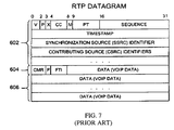
- FIG. 7 is schematic representation of a conventional RTP datagram
- FIG. 8 is schematic representation of a conventional UDP datagram
- FIG. 9 is schematic representation of a conventional RTCP datagram.
- FIG. 1 A flow diagram representation of an embodiment 10 of the method of this invention is shown in FIG. 1 .
- a network transmission event is monitored substantially at a participant location (step 20 , FIG. 1 ), and participant identifying data and identifying data related to the network transmission event is obtained (step 30 , FIG. 1 ).
- the participant identifying data and the identifying data related to the network transmission event are then provided to a predetermined (also referred to as central) monitoring location (step 40 , FIG. 1 ) and stored in a database at the central monitoring location (step 50 , FIG. 1 ).
- a database is any collection of information that is organized so that it can easily be accessed, managed, and updated.
- Identifying data related to another network transmission event is provided to the central monitoring location from another location in the network (step 60 , FIG. 1 ), where the identifying data related to another network transmission event is obtained at the another location in the network and the database is queried for specific participant identifying data corresponding to the identifying data related to the another network transmission event (step 70 , FIG. 1 ). If the query results in obtaining the specific participant identifying data, the specific participant identifying data is provided, from the central monitoring location, to the network monitoring device located at substantially the another location in the network (step 80 , FIG. 1 ). The specific participant identifying data is thereby assigned to the another network transmission event.
- the participant identifying data is obtained from a signaling transmission event.
- the identifying data relating to another network transmission event is then obtained from a real time transport event.
- the signaling transmission event is a transmission utilizing an Internet Protocol
- the signaling transmission event utilizes a signaling protocol such as, but not limited to, H.323, SIP, MGCP, or Megaco/H.248.
- FIG. 2 A graphical representation of an embodiment 100 of the system of this invention is shown in FIG. 2 and another schematic representation of an embodiment 200 of the system of this invention is shown in FIG. 3 .
- the embodiment 100 of the system of this invention shown in FIG. 2 includes a network monitoring subsystem 140 capable of monitoring a network transmission event occurring substantially at a participant location 130 , a central monitoring subsystem (server) 150 , and another network monitoring device 160 , at another network locations 170 .
- both the network monitoring subsystems 140 , 160 and the central monitoring subsystem (server) 150 are based on an implementation such as, but not limited to, that shown in FIG.
- the subsystem includes a network interface component 320 , one or more processors 310 , one or more computer readable memories 360 , and at least one other computer readable memory 340 .
- the network interface component 320 , the one or more processors 310 , the one or more computer readable memories 360 , and the one or more computer readable memories 340 are operably connected by means of a interconnection means 325 (such as, but not limited to, a common “bus”).
- network transmission and communication with the central monitoring subsystem (server) 150 occur through a network 105 ; but, signaling transmission events travel on one segment of the network while the media travel on a different segment.
- the two segments are shown in FIG. 2 as two sub-networks 110 , 120 .
- a network monitoring subsystem 140 acquires the data from a network transmission event occurring substantially at a participant location 130 in FIG. 2 by means of the acquisition hardware 215 (the acquisition hardware can be similar, but is not limited to, to that found in network analyzers such as the “J6800A Network Analyzer” of AGILENT TECHNOLOGIES, Inc.).
- the data is analyzed by means of a test instrument application code 220 .
- the test instrument application code 220 provides the means for means for obtaining, substantially at the participant location 130 , participant identifying data and identifying data related to the network transmission event.
- the signaling messages include the participant identifying data and identifying data related to the network transmission event.
- the test instrument application code 220 extracts the participant identifying data and identifying data related to the network transmission event from the signaling messages.
- software used for communicating with the central monitoring subsystem 150 (the XML APIs 225 , the communication servlet 230 and the HTTP server 235 provide the software (code) in the embodiment shown) in conjunction with the processor 310 and the network interface 320 constitute the means for providing, to the central monitoring subsystem 150 , the participant identifying data and the identifying data related to the network transmission event.
- the participant identifying data and the identifying data related to the network transmission event are received and stored by means of the software used for communicating (such as, in the embodiment shown, the HTTP layer 255 , the XML APIs 260 ) and software for data collection 262 and for data storage 265 .
- the participant identifying data and the identifying data related to the network transmission event are stored in the database 155 .
- the database 155 is located one or more computer readable memories, such as memory 340 in FIG. 4 , which has a data structure stored therein, the data structure including information resident in the database.
- the data structure comprises one or more data object pairs stored in the one or more computer readable memories, the one or more data object pairs comprising a predetermined participant identifying data object and an identifying data related to a predetermined network transmission event.
- another network transmission event is monitored by means of acquisition hardware 215 and test instrument application code (software) 220 .
- the data is analyzed by means of a test instrument application code 220 .
- the test instrument application code 220 provides the means for obtaining identifying data related to the another network transmission event.
- software used for communicating with the central monitoring subsystem 150 (the XML APIs 225 , the communication servlet 230 and the HTTP server 235 provide the software (code) in the embodiment shown) in conjunction with the processor 310 and the network interface 320 constitute the means for providing, to the central monitoring subsystem 150 , the identifying data related to the another network transmission event.
- computer readable code embodied in one or more computer usable memories, such as memory 360 in FIG. 4 , causes one or more processors at the central monitoring subsystem 150 to query the database 155 for specific participant identifying data corresponding to the identifying data related to the another network transmission event. If the query results in obtaining the specific participant identifying data, the software used for communicating (such as, in the embodiment shown, the HTTP layer 255 , the XML APIs 260 ), software for data retrieval, in conjunction with the one or more processors and the network interface at the central monitoring subsystem 150 (such as processor 310 and the network interface 320 in FIG. 4 ) constitute the means for means for providing, to the another network monitoring subsystem 160 , the specific participant identifying data.
- the software used for communicating such as, in the embodiment shown, the HTTP layer 255 , the XML APIs 260
- software for data retrieval in conjunction with the one or more processors and the network interface at the central monitoring subsystem 150 (such as processor 310 and the network interface 320 in FIG. 4
- the one or more computer readable memories in each of the network monitoring devices 140 , 160 and in the central monitoring subsystem 150 has readable code embodied therein, the computer readable code capable of causing at least one processor in each of the network monitoring devices and in the central monitoring subsystem 150 to monitor a network transmission event substantially at a participant location, obtain, substantially at the participant location 130 , participant identifying data and identifying data related to the network transmission event, provide, to the central monitoring location (subsystem) 150 , the participant identifying data and the identifying data related to the network transmission event, store in the database 155 , at the central monitoring location (subsystem) 150 , the participant identifying data and the identifying data related to the network transmission event, provide, to the central monitoring location (subsystem) 150 , from another location 170 in the network, identifying data related to another network transmission event, the identifying data related to another network transmission event being obtained at the another location in the network, query the database 155 for specific participant identifying data corresponding
- a calling telephone 130 i.e., source
- a receiving telephone 170 i.e., receiver
- the phone call initiation occurs via signaling messages (signaling transmission events) utilizing SIP as the signaling protocol.
- the SIP protocol is a text-based protocol that works above the transport layer in the TCP/IP (Transport Control Protocol/Internet Protocol) stack.
- TCP Transmission Control Protocol
- IP Internet Protocol
- SIP can use any transport protocol, including TCP (Transport Control Protocol) and UDP (User Datagram Protocol) as its transport protocol.
- TCP Transmission Control Protocol
- UDP User Datagram Protocol
- the protocol stack is shown in FIG. 5 for both SIP and H.323 as signaling protocols.
- SDP Session Description Protocol
- SDP Session Description Protocol
- RFC2327 “SDP: Session Description Protocol”, April 1998, available at http://www.ietf.org/rfc/rfc2327.txt, which is incorporated by reference herein.”
- Access to a transport protocol is obtained through use of SDP in conjunction with a protocol such as SIP.
- the steps in initiating a phone call are fairly simple: as shown in FIG. 6 , (1) the source sends an INVITE request to the receiver. Once the INVITE message reaches the receiver, (2) the receiver responds with an OK message. When the source receives the OK message, indicating the receiver has received the INVITE, (3) the source sends an ACK message, which, when received, will start the session.
- a proxy server (not shown) is utilized to receive the messages from the source and receiver and forward the messages.
- the INVITE SIP message from Alice includes:
- the first line indicates that the message is an INVITE message.
- “Via” contains the IP address, the port number and the transport protocol that Alice wants Bob to use in his response.
- the “To” line contains Bob's name and phone number.
- the “From” line contains Alice's name and Alice's phone number.
- Call-ID contains a unique identifier for the call.
- Content Type describes the message content and Content Length describes the length of the message body.
- a blank line indicate the end of the SIP headers and the beginning of the SDP session description information—“v” identifies the version of SDP, “o” identifies the owner/creator and session identifier, “p” provides the phone number, “m” provides the media description: the type, port, and possible format the source is willing to receive and send.
- the response OK message from Bob includes:
- the network monitoring subsystem 140 monitors, at source location 130 , the signaling transmission. By parsing the INVITE and OK messages and the corresponding session descriptions, the network monitoring subsystem 140 can obtain the source and receiver phone numbers, the network addresses and port numbers for the source and receiver (Alice and Bob). The source and receiver phone numbers, the network addresses and port numbers for the source and receiver are then provided to the central monitoring server 150 and stored in the database 155 .
- the network monitoring subsystem 140 is a network analyzer such as, but not limited to, a “J6800A Network Analyzer (hardware) and J6844A Telephony Network Analyzer (software)” from AGILENT TECHNOLOGIES, Inc.
- the voice (VoIP) data communication utilizes the Real-Time Transport Protocol/User Datagram Protocol/Internet Protocol (RTP/UDP/IP) as the protocol stack.
- RTP/UDP/IP Real-Time Transport Protocol/User Datagram Protocol/Internet Protocol
- FIG. 7 An example of an RTP datagram is shown in FIG. 7 .
- the RTP fields include fields for a sequence number, time stamp, synchronization source identifiers, and contributing source identifiers. (RTP is defined in RFC3550, “RTP: A Transport Protocol for Real-time applications”, July 2003, available at http://www.ietf.org/rfc/rfc3550.txt, which is herein incorporated by reference.)
- an RTP session is defined by a particular pair of destination transport addresses (one network address plus a port pair for RTP and RTCP).
- a UDP datagram is shown in FIG. 8 illustrating the port information.
- the RTP data transport protocol is augmented by a control protocol (RTCP) to allow monitoring of data delivery (allowing scalability to multicast communication), and to provide some control and identification functionality.
- RTCP control protocol
- a sender report RTCP datagram is shown in FIG. 9 .
- the other network monitoring subsystem 160 monitors, at receiver location 170 , the RTP data packets originated by the phone call (network transmission event) from the calling telephone 130 (i.e., source) to the receiving telephone 170 (i.e., receiver).
- the other network monitoring subsystem 160 is a network analyzer such as, but not limited to, a “J6800A Network Analyzer (hardware) and J6844A Telephony Network Analyzer (software)” from AGILENT TECHNOLOGIES, Inc.
- the other network monitoring subsystem 160 can obtain the pair of destination transport addresses (one network address plus a port pair for RTP and RTCP) defining the RTP session.
- the identifying data for the RTP transmission is provided to the central monitoring server (location) 150 from the location of the receiver 170 .
- the database 155 is queried for specific phone number data corresponding to the network address and port data related to the RTP transmission event. If the query results in obtaining the specific phone number data, the specific phone number data is provided, from the central monitoring location 150 , to the other network monitoring device 160 . The specific phone number data is thereby assigned to the RTP transmission event.
- the network monitoring subsystem 140 provides the source and receiver phone numbers, the network addresses and port numbers for the source and receiver to the central monitoring server 130 (location), the location of the network monitoring subsystem that provides the participant identifying data and the identifying data related to the signaling transmission event to the central monitoring server is not a limitation of this invention.
- the role of the two network monitoring systems could be interchanged in another embodiment of this invention.
- the network addresses and port numbers for the source and receiver can be obtained from a control protocol, that protocol could be utilized in practicing the invention.
- central monitoring location could be implemented in hardware, software or a combination thereof.
- An exemplary embodiment of the central monitoring location (server) is the J6782A Network Troubleshooting Center (NTC) from Agilent Technologies, Inc., a software based system. It should also be noted that this invention is not limited to that embodiment.
- the exemplary network 105 , the signaling network 110 and the media network 120 are each simplified for ease of explanation.
- the networks 105 , 110 , 120 may include more or fewer additional elements such as networks, communication links, proxies, firewalls or other security mechanisms, Internet Service Providers (ISPs), MCUs, gatekeepers, gateways, and other elements.
- ISPs Internet Service Providers
- the techniques described above may be implemented, for example, in hardware, software, firmware, or any combination thereof.
- the techniques described above may be implemented in one or more computer programs executing on a programmable computer including a processor, a storage medium readable by the processor (including, for example, volatile and non-volatile memory and/or storage elements), at least one input device, and at least one output device.
- Program code may be applied to data entered using the input device to perform the functions described and to generate output information.
- the output information may be applied to one or more output devices.
- Each computer program (code) within the scope of the claims below may be implemented in any programming language, such as assembly language, machine language, a high-level procedural programming language, or an object-oriented programming language.
- the programming language may be a compiled or interpreted programming language.
- Each computer program may be implemented in a computer program product tangibly embodied in a computer-readable storage device for execution by a computer processor. Method steps of the invention may be performed by a computer processor executing a program tangibly embodied on a computer-readable medium to perform functions of the invention by operating on input and generating output.
- Computer-readable or usable media include, for example, a floppy disk, a flexible disk, hard disk, magnetic tape, or any other magnetic medium, a CDROM, any other optical medium, punched cards, paper tape, any other physical medium with patterns of holes, a RAM, a PROM, and EPROM, a FLASH-EPROM, any other memory chip or cartridge, a carrier wave, or any other medium from which a computer can read.
Abstract
Description
| INVITE sip:bob@agi.com SIP/3.0 | ||
| Via: SIP/3.0/UDP 192.2.4.4:5060 | ||
| From: Alice <sip:111-1234@agi.com> | ||
| To: Bob <sip:111-6666@agi.com> | ||
| tag=203 941 885 | ||
| Call-ID: 123456789@192.2.4.4 | ||
| CSeq: 1 INVITE | ||
| Contact: < sip:111-1234@agi.com> | ||
| Content -Type: application/SDP | ||
| Content-Length: 182 | ||
| v= 0 | ||
| o=Alice . . . IP4 192.2.4.4 | ||
| p=1 111 111 1234 | ||
| . | ||
| m=audio 5060 RTP ... | ||
| SIP/3.0 200 OK | ||
| Via: SIP/3.0/UDP 192.2.4.4:5060 | ||
| From: Alice <sip:111-1234@agi.com> | ||
| To: Bob <sip:111-6666@agi.com> | ||
| tag=203 941 885 | ||
| Call-ID: 123456789@192.2.4.4 | ||
| CSeq: 1 INVITE | ||
| Contact: < sip:111-1234@agi.com> | ||
| Content -Type: application/SDP | ||
| Content-Length: 198 | ||
| v=0 | ||
| o= Bob . . . IN IP4 192.1.2.3 | ||
| p=1 111 111 6666 | ||
| m= audio 5004 RTP... | ||
Claims (20)
Priority Applications (5)
| Application Number | Priority Date | Filing Date | Title |
|---|---|---|---|
| US10/926,318 US7751385B2 (en) | 2004-08-25 | 2004-08-25 | Systems and methods for collecting and disbursing participant identifying data |
| DE102005020098A DE102005020098B4 (en) | 2004-08-25 | 2005-04-29 | Method and system for assigning subscriber identification data to network transmission events and computer program product |
| CNA2005100770676A CN1741469A (en) | 2004-08-25 | 2005-06-15 | System and method for collecting and assigning participant identifying data |
| GB0512949A GB2417639B (en) | 2004-08-25 | 2005-06-24 | Systems and methods for collecting and disbursing participant identifying data |
| JP2005236901A JP4695457B2 (en) | 2004-08-25 | 2005-08-17 | System and method for collecting and distributing party identification data |
Applications Claiming Priority (1)
| Application Number | Priority Date | Filing Date | Title |
|---|---|---|---|
| US10/926,318 US7751385B2 (en) | 2004-08-25 | 2004-08-25 | Systems and methods for collecting and disbursing participant identifying data |
Publications (2)
| Publication Number | Publication Date |
|---|---|
| US20060077954A1 US20060077954A1 (en) | 2006-04-13 |
| US7751385B2 true US7751385B2 (en) | 2010-07-06 |
Family
ID=34862269
Family Applications (1)
| Application Number | Title | Priority Date | Filing Date |
|---|---|---|---|
| US10/926,318 Active 2029-05-04 US7751385B2 (en) | 2004-08-25 | 2004-08-25 | Systems and methods for collecting and disbursing participant identifying data |
Country Status (5)
| Country | Link |
|---|---|
| US (1) | US7751385B2 (en) |
| JP (1) | JP4695457B2 (en) |
| CN (1) | CN1741469A (en) |
| DE (1) | DE102005020098B4 (en) |
| GB (1) | GB2417639B (en) |
Cited By (7)
| Publication number | Priority date | Publication date | Assignee | Title |
|---|---|---|---|---|
| US20110321035A1 (en) * | 2006-10-02 | 2011-12-29 | David Petersen | Methods and apparatus to collect wireless information |
| US20120084331A1 (en) * | 2009-06-10 | 2012-04-05 | Alcatel Lucent | Method And Scout Agent For Building A Source Database |
| US9203642B2 (en) | 2007-07-09 | 2015-12-01 | The Nielsen Company (Us), Llc. | Method and system for collecting data on a wireless device |
| US9225845B2 (en) | 2006-10-02 | 2015-12-29 | The Nielsen Company (Us), Llc | Methods and apparatus for collecting information about portable device usage |
| US9449279B2 (en) | 2010-06-24 | 2016-09-20 | The Nielsen Company (Us), Llc | Network server arrangements for processing non-parametric, multi-dimensional, spatial and temporal human behavior or technical observations measured pervasively, and related methods for the same |
| US9613363B2 (en) | 2010-08-25 | 2017-04-04 | The Nielsen Company (Us), Llc | Methods, systems and apparatus to generate market segmentation data with anonymous location data |
| US11502914B2 (en) | 2009-05-08 | 2022-11-15 | The Nielsen Company (Us), Llc | Systems and methods for behavioural and contextual data analytics |
Families Citing this family (4)
| Publication number | Priority date | Publication date | Assignee | Title |
|---|---|---|---|---|
| US8539065B2 (en) * | 2006-07-26 | 2013-09-17 | Cisco Technology, Inc. | Method and apparatus for providing access to real time control protocol information for improved media quality control |
| US20080037518A1 (en) * | 2006-07-26 | 2008-02-14 | Parameswaran Kumarasamy | Method and apparatus for voice over internet protocol call signaling and media tracing |
| CN101166178B (en) * | 2006-10-16 | 2010-05-12 | 华为技术有限公司 | Session description protocol version negotiation method, system and network entity |
| EP3085046B1 (en) * | 2013-12-20 | 2020-02-05 | Telefonaktiebolaget LM Ericsson (publ) | Session initiation handling |
Citations (29)
| Publication number | Priority date | Publication date | Assignee | Title |
|---|---|---|---|---|
| JPH01137768A (en) | 1987-11-25 | 1989-05-30 | Mitsubishi Electric Corp | Terminal equipment connection system |
| US5557748A (en) * | 1995-02-03 | 1996-09-17 | Intel Corporation | Dynamic network configuration |
| US6282279B1 (en) * | 1997-02-10 | 2001-08-28 | At&T Corp. | Method and system for processing outbound service calls via a network adjunct platform |
| US20020009184A1 (en) * | 1999-10-22 | 2002-01-24 | J. Mitchell Shnier | Call classification indication using sonic means |
| US20020159442A1 (en) * | 2000-05-08 | 2002-10-31 | Vincent Quigley | Method of indicating the origin of a mobile user in a data network |
| DE10121496A1 (en) | 2001-05-03 | 2002-11-14 | Gten Ag | Method and arrangement for location-independent monitoring of voice and / or data network connections by users |
| US20020186685A1 (en) | 2001-06-11 | 2002-12-12 | O'brien James D. | Voice over internet protocol real time protocol routing |
| US20030031165A1 (en) | 2001-08-10 | 2003-02-13 | O'brien James D. | Providing voice over internet protocol networks |
| US6567399B1 (en) * | 1999-05-05 | 2003-05-20 | 3Com Corporation | Hi-fidelity line card |
| US20030133450A1 (en) * | 2002-01-08 | 2003-07-17 | Baum Robert T. | Methods and apparatus for determining the port and/or physical location of an IP device and for using that information |
| JP2004032265A (en) | 2002-06-25 | 2004-01-29 | Iwatsu Electric Co Ltd | Internet protocol telephony system and its terminal |
| US20040021889A1 (en) * | 2002-07-30 | 2004-02-05 | Mcafee David A. | Method of transmitting information from a document to a remote location, and a computer peripheral device |
| US20040037267A1 (en) * | 2002-08-22 | 2004-02-26 | Bennett Timothy Mark | Monitoring an RTP data stream based on a phone call |
| US20040066753A1 (en) | 2002-10-04 | 2004-04-08 | Grovenburg William Grant | System and method to monitor RTP streams using RTCP SR/RR packet information |
| US20040127231A1 (en) * | 2001-07-23 | 2004-07-01 | Erez Dor | Location-based service protocol |
| US6788766B2 (en) * | 2001-06-02 | 2004-09-07 | James D. Logan | Methods and apparatus for providing location dependent cellular telephone communications |
| US20050031114A1 (en) * | 1997-03-31 | 2005-02-10 | Sbc Laboratories, Inc. | Apparatus and method for intelligent call routing and call return |
| US6862277B2 (en) * | 2002-10-28 | 2005-03-01 | Motorola, Inc. | Method and apparatus for multi-media communication over multiple networks |
| JP2005094646A (en) | 2003-09-19 | 2005-04-07 | Sharp Corp | Ip telephone set and voip compatible router |
| US6934279B1 (en) * | 2000-03-13 | 2005-08-23 | Nortel Networks Limited | Controlling voice communications over a data network |
| US20050201362A1 (en) * | 2004-02-20 | 2005-09-15 | Klein Mark D. | Call management |
| US20050272448A1 (en) * | 2004-06-08 | 2005-12-08 | Lg Electronics Inc. | Caller location identifying system and method in a communication network |
| US20060044407A1 (en) * | 2004-08-26 | 2006-03-02 | Sprint Spectrum L.P. | Method and system for delivering photos to called destinations |
| US7167468B2 (en) * | 1999-11-08 | 2007-01-23 | Mci, Llc | Internet protocol telephony voice/video message deposit and retrieval |
| US7382869B2 (en) * | 2002-09-06 | 2008-06-03 | At&T Delaware Intellectual Property, Inc. | Real time customer service data manipulation to allow multiple services per trigger type |
| US7460658B2 (en) * | 2003-09-16 | 2008-12-02 | Alcatel Lucent | Apparatus, and an associated method, for selectably and automatically redirecting a telephonic call to a secondary location |
| US7551922B2 (en) * | 2004-07-08 | 2009-06-23 | Carrier Iq, Inc. | Rule based data collection and management in a wireless communications network |
| US7561520B2 (en) * | 2004-06-04 | 2009-07-14 | Holloway J Michael | Capacity limiting platform system and method |
| US7580405B2 (en) * | 2004-05-27 | 2009-08-25 | At&T Intellectual Property I, L. P. | Method and system for routing emergency data communications |
Family Cites Families (4)
| Publication number | Priority date | Publication date | Assignee | Title |
|---|---|---|---|---|
| JP4044981B2 (en) * | 1996-11-12 | 2008-02-06 | 日鉱金属株式会社 | Method for removing impurities from waste acid |
| JP2003348252A (en) * | 2002-05-29 | 2003-12-05 | Toshiba Corp | Cable modem, speaking information recording apparatus and method, and speaking information management program |
| JP3639269B2 (en) * | 2002-07-04 | 2005-04-20 | エヌ・ティ・ティ・コムウェア株式会社 | VoIP voice monitoring method and VoIP voice monitoring system |
| JP4471703B2 (en) * | 2004-03-30 | 2010-06-02 | 富士通株式会社 | Communication quality analysis system, analysis apparatus, communication quality analysis method, and computer program |
-
2004
- 2004-08-25 US US10/926,318 patent/US7751385B2/en active Active
-
2005
- 2005-04-29 DE DE102005020098A patent/DE102005020098B4/en active Active
- 2005-06-15 CN CNA2005100770676A patent/CN1741469A/en active Pending
- 2005-06-24 GB GB0512949A patent/GB2417639B/en not_active Expired - Fee Related
- 2005-08-17 JP JP2005236901A patent/JP4695457B2/en active Active
Patent Citations (30)
| Publication number | Priority date | Publication date | Assignee | Title |
|---|---|---|---|---|
| JPH01137768A (en) | 1987-11-25 | 1989-05-30 | Mitsubishi Electric Corp | Terminal equipment connection system |
| US5557748A (en) * | 1995-02-03 | 1996-09-17 | Intel Corporation | Dynamic network configuration |
| US6282279B1 (en) * | 1997-02-10 | 2001-08-28 | At&T Corp. | Method and system for processing outbound service calls via a network adjunct platform |
| US20050031114A1 (en) * | 1997-03-31 | 2005-02-10 | Sbc Laboratories, Inc. | Apparatus and method for intelligent call routing and call return |
| US7499536B2 (en) * | 1997-03-31 | 2009-03-03 | At&T Labs, Inc. | Apparatus and method for intelligent call routing and call return |
| US6567399B1 (en) * | 1999-05-05 | 2003-05-20 | 3Com Corporation | Hi-fidelity line card |
| US20020009184A1 (en) * | 1999-10-22 | 2002-01-24 | J. Mitchell Shnier | Call classification indication using sonic means |
| US7167468B2 (en) * | 1999-11-08 | 2007-01-23 | Mci, Llc | Internet protocol telephony voice/video message deposit and retrieval |
| US6934279B1 (en) * | 2000-03-13 | 2005-08-23 | Nortel Networks Limited | Controlling voice communications over a data network |
| US20020159442A1 (en) * | 2000-05-08 | 2002-10-31 | Vincent Quigley | Method of indicating the origin of a mobile user in a data network |
| DE10121496A1 (en) | 2001-05-03 | 2002-11-14 | Gten Ag | Method and arrangement for location-independent monitoring of voice and / or data network connections by users |
| US6788766B2 (en) * | 2001-06-02 | 2004-09-07 | James D. Logan | Methods and apparatus for providing location dependent cellular telephone communications |
| US20020186685A1 (en) | 2001-06-11 | 2002-12-12 | O'brien James D. | Voice over internet protocol real time protocol routing |
| US20040127231A1 (en) * | 2001-07-23 | 2004-07-01 | Erez Dor | Location-based service protocol |
| US20030031165A1 (en) | 2001-08-10 | 2003-02-13 | O'brien James D. | Providing voice over internet protocol networks |
| US20030133450A1 (en) * | 2002-01-08 | 2003-07-17 | Baum Robert T. | Methods and apparatus for determining the port and/or physical location of an IP device and for using that information |
| JP2004032265A (en) | 2002-06-25 | 2004-01-29 | Iwatsu Electric Co Ltd | Internet protocol telephony system and its terminal |
| US20040021889A1 (en) * | 2002-07-30 | 2004-02-05 | Mcafee David A. | Method of transmitting information from a document to a remote location, and a computer peripheral device |
| US20040037267A1 (en) * | 2002-08-22 | 2004-02-26 | Bennett Timothy Mark | Monitoring an RTP data stream based on a phone call |
| US7382869B2 (en) * | 2002-09-06 | 2008-06-03 | At&T Delaware Intellectual Property, Inc. | Real time customer service data manipulation to allow multiple services per trigger type |
| US20040066753A1 (en) | 2002-10-04 | 2004-04-08 | Grovenburg William Grant | System and method to monitor RTP streams using RTCP SR/RR packet information |
| US6862277B2 (en) * | 2002-10-28 | 2005-03-01 | Motorola, Inc. | Method and apparatus for multi-media communication over multiple networks |
| US7460658B2 (en) * | 2003-09-16 | 2008-12-02 | Alcatel Lucent | Apparatus, and an associated method, for selectably and automatically redirecting a telephonic call to a secondary location |
| JP2005094646A (en) | 2003-09-19 | 2005-04-07 | Sharp Corp | Ip telephone set and voip compatible router |
| US20050201362A1 (en) * | 2004-02-20 | 2005-09-15 | Klein Mark D. | Call management |
| US7580405B2 (en) * | 2004-05-27 | 2009-08-25 | At&T Intellectual Property I, L. P. | Method and system for routing emergency data communications |
| US7561520B2 (en) * | 2004-06-04 | 2009-07-14 | Holloway J Michael | Capacity limiting platform system and method |
| US20050272448A1 (en) * | 2004-06-08 | 2005-12-08 | Lg Electronics Inc. | Caller location identifying system and method in a communication network |
| US7551922B2 (en) * | 2004-07-08 | 2009-06-23 | Carrier Iq, Inc. | Rule based data collection and management in a wireless communications network |
| US20060044407A1 (en) * | 2004-08-26 | 2006-03-02 | Sprint Spectrum L.P. | Method and system for delivering photos to called destinations |
Non-Patent Citations (3)
| Title |
|---|
| Handley, M. et al. "SDP: Session Description Protocol." © The Internet Society 1998. Retrieved from www.ietf.org/rfc/rfc2327.txt on Jul. 23, 2004. |
| Rosenberg, J. et al. "SIP: Session Initiation Protocol." © the Internet Society 2002. Retrieved from www.ietf.org/rfc/rfc3261.txt on Aug. 17, 2004. |
| Schulzrinne, H. et al. "RTP: A Transport Protocol for Real-Time Applications." © The Internet Society 2003. Retrieved from www.ietf.org/rfc/rfc3550.txt on Aug. 17, 2004. |
Cited By (15)
| Publication number | Priority date | Publication date | Assignee | Title |
|---|---|---|---|---|
| US9432868B2 (en) | 2006-10-02 | 2016-08-30 | The Nielsen Company (Us), Llc | Methods and apparatus to collect wireless information |
| US8538343B2 (en) * | 2006-10-02 | 2013-09-17 | The Nielsen Company (Us), Llc | Methods and apparatus to collect wireless information |
| US9008586B2 (en) | 2006-10-02 | 2015-04-14 | The Nielsen Company (Us), Llc | Methods and apparatus to collect wireless information |
| US9225845B2 (en) | 2006-10-02 | 2015-12-29 | The Nielsen Company (Us), Llc | Methods and apparatus for collecting information about portable device usage |
| US20110321035A1 (en) * | 2006-10-02 | 2011-12-29 | David Petersen | Methods and apparatus to collect wireless information |
| US9203642B2 (en) | 2007-07-09 | 2015-12-01 | The Nielsen Company (Us), Llc. | Method and system for collecting data on a wireless device |
| US11502914B2 (en) | 2009-05-08 | 2022-11-15 | The Nielsen Company (Us), Llc | Systems and methods for behavioural and contextual data analytics |
| US20120084331A1 (en) * | 2009-06-10 | 2012-04-05 | Alcatel Lucent | Method And Scout Agent For Building A Source Database |
| US9449279B2 (en) | 2010-06-24 | 2016-09-20 | The Nielsen Company (Us), Llc | Network server arrangements for processing non-parametric, multi-dimensional, spatial and temporal human behavior or technical observations measured pervasively, and related methods for the same |
| US9613363B2 (en) | 2010-08-25 | 2017-04-04 | The Nielsen Company (Us), Llc | Methods, systems and apparatus to generate market segmentation data with anonymous location data |
| US10380643B2 (en) | 2010-08-25 | 2019-08-13 | The Nielsen Company (Us), Llc | Methods, systems and apparatus to generate market segmentation data with anonymous location data |
| US10713687B2 (en) | 2010-08-25 | 2020-07-14 | The Nielsen Company (Us), Llc | Methods, systems and apparatus to generate market segmentation data with anonymous location data |
| US11170410B2 (en) | 2010-08-25 | 2021-11-09 | The Nielsen Company (Us), Llc | Methods, systems and apparatus to generate market segmentation data with anonymous location data |
| US9996855B2 (en) | 2010-08-25 | 2018-06-12 | The Nielsen Company (Us), Llc | Methods, systems and apparatus to generate market segmentation data with anonymous location data |
| US11769174B2 (en) | 2010-08-25 | 2023-09-26 | The Nielsen Company (Us), Llc | Methods, systems and apparatus to generate market segmentation data with anonymous location data |
Also Published As
| Publication number | Publication date |
|---|---|
| JP2006067579A (en) | 2006-03-09 |
| JP4695457B2 (en) | 2011-06-08 |
| CN1741469A (en) | 2006-03-01 |
| GB2417639B (en) | 2007-08-01 |
| DE102005020098A1 (en) | 2006-03-09 |
| DE102005020098B4 (en) | 2011-06-30 |
| GB2417639A (en) | 2006-03-01 |
| GB0512949D0 (en) | 2005-08-03 |
| US20060077954A1 (en) | 2006-04-13 |
Similar Documents
| Publication | Publication Date | Title |
|---|---|---|
| JP4695457B2 (en) | System and method for collecting and distributing party identification data | |
| US8874762B2 (en) | Session initiation protocol adaptor | |
| JP5363461B2 (en) | Group call function inquiry | |
| US9148359B2 (en) | Correlation of media plane and signaling plane of media services in a packet-switched network | |
| US20040252683A1 (en) | System, method , and computer program product for resolving addressing in a network including a network address translator | |
| US8503429B2 (en) | Processing requests and generating responses in session initiation protocol (SIP) | |
| US10601880B2 (en) | Conference reconstruction in SIP networks | |
| US9246955B2 (en) | Capability query handling in a communication network | |
| Wu et al. | Guidelines for Use of the RTP Monitoring Framework | |
| US20170064075A1 (en) | Continuous call recording | |
| US20150095420A1 (en) | System and method to identify secure media streams to conference watchers in sip messaging | |
| EP2466799B1 (en) | Correlation of media plane and signaling plane of media services in a packet-switched network | |
| US8219610B2 (en) | Content providing system, monitoring server, and SIP proxy server | |
| KR100894906B1 (en) | Terminal unit for providing IP multimedia service on the basis of session initiaion protocol, call session control function device, method of transmitting and receiving thereof | |
| US20060294248A1 (en) | Automatic server configuration based on user agent | |
| Raty et al. | Network traffic analyzing and monitoring locations in the IP Multimedia Subsystem | |
| EP2863596A1 (en) | Sbc for cloud environment and method for operating sbc | |
| CN117714428A (en) | SIP data transmission method, device, storage medium and equipment | |
| Bose et al. | Linear Feedback Control of n-Dimensional Quadratic Systems | |
| CN116668624A (en) | Link detection method, device and equipment | |
| KALPANA | A new scheme to reduce session establishment time in session initiation protocol (SIP) | |
| EP2066097B1 (en) | Scenario tracking in a network | |
| CN117749773A (en) | Data transmission method, device and system and electronic equipment | |
| Gasterstädt et al. | Media Connectivity in SIP Infrastructures: Provider Awareness, Approaches, Consequences, and Applicability | |
| Yeh et al. | Designing an integrated voice, video, and instant message service system in SIP-based IP networks |
Legal Events
| Date | Code | Title | Description |
|---|---|---|---|
| AS | Assignment |
Owner name: AGILENT TECHNOLOGIES, INC., COLORADO Free format text: ASSIGNMENT OF ASSIGNORS INTEREST;ASSIGNORS:MONK, JOHN M.;BENNETT, TIMOTHY M.;BLOMQUIST, SCOTT A.;REEL/FRAME:015569/0747 Effective date: 20040823 |
|
| AS | Assignment |
Owner name: JDS UNIPHASE CORPORATION,CALIFORNIA Free format text: ASSIGNMENT OF ASSIGNORS INTEREST;ASSIGNOR:AGILENT TECHNOLOGIES, INC.;REEL/FRAME:024403/0545 Effective date: 20100430 Owner name: JDS UNIPHASE CORPORATION, CALIFORNIA Free format text: ASSIGNMENT OF ASSIGNORS INTEREST;ASSIGNOR:AGILENT TECHNOLOGIES, INC.;REEL/FRAME:024403/0545 Effective date: 20100430 |
|
| STCF | Information on status: patent grant |
Free format text: PATENTED CASE |
|
| FPAY | Fee payment |
Year of fee payment: 4 |
|
| AS | Assignment |
Owner name: VIAVI SOLUTIONS INC., CALIFORNIA Free format text: CHANGE OF NAME;ASSIGNOR:JDS UNIPHASE CORPORATION;REEL/FRAME:037057/0627 Effective date: 20150731 |
|
| FEPP | Fee payment procedure |
Free format text: PAYER NUMBER DE-ASSIGNED (ORIGINAL EVENT CODE: RMPN); ENTITY STATUS OF PATENT OWNER: LARGE ENTITY Free format text: PAYOR NUMBER ASSIGNED (ORIGINAL EVENT CODE: ASPN); ENTITY STATUS OF PATENT OWNER: LARGE ENTITY |
|
| MAFP | Maintenance fee payment |
Free format text: PAYMENT OF MAINTENANCE FEE, 8TH YEAR, LARGE ENTITY (ORIGINAL EVENT CODE: M1552) Year of fee payment: 8 |
|
| AS | Assignment |
Owner name: WELLS FARGO BANK, NATIONAL ASSOCIATION, AS ADMINISTRATIVE AGENT, COLORADO Free format text: SECURITY INTEREST;ASSIGNORS:VIAVI SOLUTIONS INC.;3Z TELECOM, INC.;ACTERNA LLC;AND OTHERS;REEL/FRAME:052729/0321 Effective date: 20200519 |
|
| MAFP | Maintenance fee payment |
Free format text: PAYMENT OF MAINTENANCE FEE, 12TH YEAR, LARGE ENTITY (ORIGINAL EVENT CODE: M1553); ENTITY STATUS OF PATENT OWNER: LARGE ENTITY Year of fee payment: 12 |
|
| AS | Assignment |
Owner name: RPC PHOTONICS, INC., NEW YORK Free format text: TERMINATIONS OF SECURITY INTEREST AT REEL 052729, FRAME 0321;ASSIGNOR:WELLS FARGO BANK, NATIONAL ASSOCIATION, AS ADMINISTRATIVE AGENT;REEL/FRAME:058666/0639 Effective date: 20211229 Owner name: VIAVI SOLUTIONS INC., CALIFORNIA Free format text: TERMINATIONS OF SECURITY INTEREST AT REEL 052729, FRAME 0321;ASSIGNOR:WELLS FARGO BANK, NATIONAL ASSOCIATION, AS ADMINISTRATIVE AGENT;REEL/FRAME:058666/0639 Effective date: 20211229 |