US7761137B2 - Biopsy site marker deployment device - Google Patents
Biopsy site marker deployment device Download PDFInfo
- Publication number
- US7761137B2 US7761137B2 US11/305,141 US30514105A US7761137B2 US 7761137 B2 US7761137 B2 US 7761137B2 US 30514105 A US30514105 A US 30514105A US 7761137 B2 US7761137 B2 US 7761137B2
- Authority
- US
- United States
- Prior art keywords
- marker
- cannula
- push rod
- deployment
- aperture
- Prior art date
- Legal status (The legal status is an assumption and is not a legal conclusion. Google has not performed a legal analysis and makes no representation as to the accuracy of the status listed.)
- Active, expires
Links
- 0 CC(CCCC1)=*1*#C Chemical compound CC(CCCC1)=*1*#C 0.000 description 1
Images


Classifications
-
- A—HUMAN NECESSITIES
- A61—MEDICAL OR VETERINARY SCIENCE; HYGIENE
- A61B—DIAGNOSIS; SURGERY; IDENTIFICATION
- A61B90/00—Instruments, implements or accessories specially adapted for surgery or diagnosis and not covered by any of the groups A61B1/00 - A61B50/00, e.g. for luxation treatment or for protecting wound edges
- A61B90/39—Markers, e.g. radio-opaque or breast lesions markers
- A61B2090/3987—Applicators for implanting markers
Definitions
- Biopsies and other techniques are commonly performed to remove a tissue sample from a selected site within the body. The sample may then be examined and analyzed. Many biopsy devices make use of a hollow tube that forms a working channel. The hollow tube is inserted into the site from where the sample is to be taken. The hollow tube frequently includes an aperture in communication with the working channel. The aperture provides access between the working channel and the site to be analyzed, which may be at some sub-cutaneous depth. This access allows samples to be taken from the desired location.
- the aperture is placed adjacent to the site from which the sample is to be taken. Thereafter, the tissue is drawn through the aperture and into the working channel, such as through the use of a vacuum.
- a thin tube commonly referred to as a cutting cannula is then pushed through the working channel.
- the cutting cannula is sized to fit closely to the inner wall of the working channel.
- the cutting cannula cuts the tissue extending into the working channel. The tissue may then be removed and examined.
- markers may be used.
- the markers frequently include a relatively small device or material that is readily identifiable.
- the markers are often introduced using a deployment device in conjunction with the working channel of the biopsy device.
- Drag out When introduced through the working channel of a biopsy device, current marker deployment devices do not effectively close off the aperture, resulting in gaps or dead space between the biopsy device and the marker device. This creates the potential for the marker to fall partially or completely back into the aperture of the biopsy device. As a result, the marker can be pulled out of the biopsy site when the biopsy device is removed. This is known as “drag out.” Drag out can lead to the biopsy site not being identified, an incorrect area of tissue being identified, and treatment of the wrong site.
- Marker deployment devices are provided herein for depositing site markers.
- the markers may be introduced to the biopsy sites through apertures, such as an aperture formed in a working channel of a biopsy device and/or an aperture formed in the deployment device.
- the deployment devices discussed herein are configured to close the aperture after the marker has been deposited, such that the marker will not fall partially or completely back into the deployment device. This configuration reduces the possibility that the marker will be dragged out when the deployment device is removed.
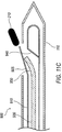
- FIG. 1 illustrates a perspective view of a deployment device according to one exemplary embodiment.
- FIG. 2 illustrates a cross-sectional view of a distal end of the deployment device of FIG. 1 in more detail.
- FIGS. 3A-3B are cross-sectional views that illustrate the deployment action of the deployment device of FIG. 2 .
- FIG. 4 is illustrates a cross-sectional view of a distal end of an alternative embodiment of a deployment device according to one exemplary embodiment.
- FIG. 5 illustrates a cross-sectional view of the deployment device of FIG. 4 at a first position relative to a working channel of a biopsy device.
- FIG. 6 is a cross-sectional view of the deployment device of FIG. 4 illustrating the deployment action of the deployment device.
- FIG. 7 illustrates a cross-sectional view of another embodiment of a deployment device in a first position according to one exemplary embodiment.
- FIG. 8 is a cross-sectional view of the deployment device of FIG. 7 illustrating the deployment action of the deployment device depositing a marker.
- FIG. 9 illustrates a cross-sectional view of another embodiment of a deployment device according to one exemplary embodiment.
- FIG. 10 illustrates a cross-sectional view of the deployment device of FIG. 9 in the process of deploying a marker.
- FIG. 11A illustrates a cross-sectional view of the deployment device of FIG. 9 in the process of deploying the marker.
- FIG. 11B illustrates a cross-sectional view of the deployment device of FIG. 9 in an intermediate stage of deploying the marker.
- FIG. 11C illustrates a cross-sectional view of the deployment device of FIG. 9 in a final stage of deploying the marker.
- FIG. 12A illustrates a cross-sectional view of another embodiment of a deployment device according to one exemplary embodiment.
- FIG. 12B illustrates a cross-sectional view of a portion of the deployment device of FIG. 12A taken along lines 12 B- 12 B.
- FIG. 13 illustrates a cross-sectional view of the deployment device of FIG. 12A in the process of deploying a marker.
- FIG. 14 illustrates a cross-sectional view of the deployment device of FIG. 12A after the marker has been deployed by the deployment device and push rod has been retracted.
- FIG. 15A illustrates a cross-sectional view of the deployment device of FIG. 12A after the marker has been deployed and the push rod has secured a flexible member in place.
- FIG. 15B illustrates a cross sectional view of the deployment device of FIG. 15A taken along lines 15 B- 15 B.
- FIG. 16 illustrates a cross-sectional view of an alternative embodiment of a deployment device according to one exemplary embodiment.
- the marker deployment device includes an elongated introduction device and a deployment assembly.
- the deployment assembly deposits the marker through an aperture, and then at least substantially closes the aperture. Maintaining the aperture in a substantially closed position reduces the possibility that the marker will fall back into deployment device.
- FIG. 1 illustrates a marker deployment device ( 100 ) coupled to a working channel ( 110 ), such as the working channel of a biopsy device according to one exemplary embodiment.
- the working channel ( 110 ) has an aperture ( 120 ) defined therein.
- the deployment device ( 100 ) may include a hub ( 130 ) to which a cannula ( 131 ), (as best seen in FIG. 2 ) is connected. The cannula is selectively received within the working channel ( 110 ).
- the deployment device ( 100 ) also includes a push rod ( 140 ), which extends into the hub ( 130 ).
- a push rod ( 140 ) extends into the hub ( 130 ).
- FIG. 1 a relatively large portion of the hub ( 130 ) is shown in contact with the proximal end of the working channel ( 110 ). This contact prevents further movement of the deployment device ( 100 ) within the working channel ( 110 ).
- the push rod ( 140 ) may then be advanced to deploy a marker.
- the proximal end of the push rod ( 140 ) may include a plunger ( 141 ) that is relatively large compared to the rest of the push rod ( 140 ), plunger ( 141 ) which may facilitate movement of the push rod ( 140 ) relative to the working channel ( 110 ) as the deployment device ( 100 ) is actuated.
- a plunger ( 141 ) that is relatively large compared to the rest of the push rod ( 140 )
- plunger ( 141 ) which may facilitate movement of the push rod ( 140 ) relative to the working channel ( 110 ) as the deployment device ( 100 ) is actuated.
- Other components of the deployment device ( 100 ) will be discussed in isolation with reference to FIG. 2 , while the operation of the deployment device ( 100 ) will be discussed further with reference to FIGS. 3A-3B .
- FIG. 2 illustrates a distal end ( 212 ) of the deployment device ( 100 ) in more detail.
- the distal end shall refer to a portion nearer the biopsy site while proximal shall refer to the end opposite the distal end.
- the marker deployment device ( 100 ) includes the cannula ( 131 ), the push rod ( 140 ), and an expandable member ( 200 ).
- the expandable member ( 200 ) forms a deployment assembly.
- the deployment assembly is configured to deposit a marker ( 210 ) while minimizing space between the deployment device ( 200 ) and the device or area used to introduce the deployment device.
- the distal end ( 212 ) of the cannula ( 130 ) is open.
- the distal end of the push rod ( 140 ) is coupled to the expandable member ( 200 ). Consequently, translation of the push rod ( 140 ) relative to the cannula ( 131 ) results in movement of the expandable member ( 200 ) relative to the cannula ( 131 ).
- the expandable member ( 200 ) is configured to receive a marker ( 210 ).
- the expandable member ( 200 ) may be compressed by a predetermined amount to form a depression ( 214 ) appropriately sized such that the marker ( 210 ) may be received therein.
- FIG. 2 illustrates the push rod ( 140 ), expandable member ( 200 ), and marker ( 210 ) retained within the cannula ( 131 ) at a first, pre-deployment position. In this first position, the expandable member ( 200 ) may be compressed within the cannula ( 131 ).
- the deployment device ( 100 ) is delivered through the working channel ( 110 ) of a biopsy device or other surgical device.
- the cannula ( 131 ) is sized to slide relative to the working channel of the biopsy device.
- the distal end ( 212 ) of the deployment device ( 100 ) may be introduced to the proximal end of the working channel ( 110 ).
- the push rod ( 140 ), the expandable member ( 200 ), and the marker ( 210 ) are maintained in their first position relative to the cannula ( 131 ).
- the distal end of the deployment device ( 100 ) is urged toward the distal end of the working channel ( 110 ) a predetermined distance.
- the hub ( 130 ) comes into contact with the proximal end of the working channel ( 110 ) to serve as a stop member to define the predetermined distance.
- the cannula ( 131 ) is prevented from advancing further. With the location of the cannula ( 130 ) thus constrained, the push rod ( 140 ) may be actuated to deploy the marker ( 210 ).
- FIG. 3A illustrates the cannula ( 130 ) located within the working channel ( 110 ) of the biopsy device.
- the expandable member ( 200 ) contacts a wall ( 216 ) at the distal end of the working channel ( 110 ) adjacent aperture ( 120 ).
- the expandable member ( 200 ) acts against wall ( 216 ) and the internal surface of working channel ( 110 ) so to expand to fill the working channel ( 110 ).
- the expandable member ( 200 ) expands through with the aperture ( 120 ; best seen in FIG. 3A ) in the working channel ( 110 ).
- the expandable member ( 200 ) is expanded, thereby substantially filling the aperture ( 120 ).
- the expandable member ( 200 ) is made of a resilient material that is compressed while in the cannula ( 131 ) and the working channel ( 110 ).
- Such materials may include, without limitation, nitinol, an expandable mesh material, and/or shape memory material.
- the material may be substantially uncompressed or slightly compressed while in the cannula ( 131 ) and/or the working channel ( 110 ).
- the push rod ( 140 ) is advanced sufficiently the expandable member ( 200 ) comes into contact with the wall ( 216 ) at the distal end of the working channel ( 110 ).
- Advancing the push rod ( 140 ) compresses the expandable member ( 200 ) about its length within the working channel ( 110 ). This compression causes the expandable member ( 200 ) to expand in a direction perpendicular to the compression. This expansion causes the expandable member ( 200 ) to expand through the aperture ( 120 ).
- the expandable member ( 200 ) As the expandable member ( 200 ) expands in a perpendicular direction, it carries the marker ( 210 ) through the aperture ( 120 ) and into the surrounding biopsy cavity.
- the expandable member ( 200 ) may be expanded a predetermined amount to thereby deposit the marker ( 210 ) into the biopsy cavity. Thereafter, the expansion of the expandable member ( 200 ) may be reduced slightly to provide spacing between the expandable member ( 200 ) and the deposited marker ( 210 ).
- the expandable member ( 200 ) remains sufficiently expanded to substantially fill the aperture ( 120 ), thereby sealing the aperture ( 120 ) and preventing the marker ( 210 ) from falling back into the deployment device ( 100 ). Further, after deployment the working channel ( 110 ) may be rotated such that the opening ( 120 ) is rotated away from the deployed marker ( 210 ), thereby further preventing that the marker ( 210 ) does not fall back into the working channel ( 110 ).
- the deployment device ( 100 ) may then be withdrawn, such as by withdrawing the working channel ( 110 ) with the expandable member ( 200 ) expanded to maintain a seal about the aperture ( 120 ).
- the aperture remains substantially sealed, thereby minimizing or reducing the possibility that the marker ( 210 ) will fall partially or completely into the working channel ( 110 ) and thus be dragged out.
- the marker deployment device ( 100 ) has been described with reference to a working channel ( 110 ), those of skill in the art will appreciate that other configurations are possible.
- the deployment device ( 100 ) may be introduced to the biopsy site by way of the tissue track created by a biopsy device in creating the biopsy site.
- Other configurations are also possible, as will now be discussed in more detail.
- FIGS. 4 , 5 , and 6 illustrate a deployment device ( 400 ) that includes a cannula ( 410 ), a push rod ( 420 ), a protruding member ( 430 ), a receiving member ( 440 ), and a strip of flexible material ( 450 ).
- FIG. 4 illustrates the deployment device ( 400 ) in isolation.
- FIG. 5 illustrates the deployment device ( 400 ) at a first, pre-deployment position relative to a working channel ( 110 ).
- FIG. 6 illustrates the deployment device ( 400 ) deploying a marker ( 210 ).
- a seat ( 460 ) is defined in the push rod ( 420 ).
- a strip of flexible material hereinafter referred to as a flexible strip ( 450 ), has a first position that is coupled to the receiving member ( 440 ).
- the receiving member is detachably coupled to a distal end of push rod ( 420 ).
- the flexible strip ( 450 ) extends from the receiving member ( 440 ), and along the surface of a seat ( 460 ).
- a second portion of flexible strip ( 450 ) is connected to a portion of push rod ( 420 ), adjacent seat ( 460 ), opposite receiving member ( 440 ).
- the distal end of the cannula ( 410 ) is substantially closed. Additionally, a cannula aperture ( 470 ) is defined near the distal end of the cannula ( 410 ). According to the present exemplary embodiment, the protruding member ( 430 ) is disposed at or near the closed distal end of the cannula ( 410 ). The protruding member ( 430 ) is configured to be matingly coupled to the receiving member ( 440 ).
- the cannula ( 410 ) may be advanced relative to the working channel ( 110 ) until the distal end of the cannula ( 410 ) comes into contact with the distal end of the working channel ( 110 ).
- the cannula aperture ( 470 ) is aligned relative to the aperture ( 120 ) defined in the working channel ( 110 ).
- the push rod ( 420 ) may be advanced until the receiving member ( 440 ) comes into contact and engages with the protruding member ( 430 ). This contact couples the receiving member ( 440 ) to the protruding member ( 430 ).
- the seat ( 460 ) is aligned relative to the both the cannula aperture ( 470 ) and the aperture ( 120 ) defined in the working channel ( 110 ).
- the push rod ( 420 ) may deploy the marker ( 210 ) while minimizing the possibility that the marker ( 210 ) will fall completely or partially back into the seat ( 460 ), the cannula aperture ( 470 ), and/or the aperture ( 120 ) defined in the working channel ( 110 ).
- a configuration is shown in FIG. 6 .
- the protruding member ( 430 ) is coupled to the receiving member ( 440 ). As the push rod ( 420 ) is retracted, the protruding member ( 430 ) retains the receiving member ( 440 ) in contact therewith.
- the marker ( 210 ) is also upwardly displaced.
- the cannula aperture ( 470 ) and the aperture ( 120 ) in the working channel ( 110 ) are aligned.
- the marker ( 210 ) is driven upward, it is urged through the cannula aperture ( 470 ), through the aperture ( 120 ) in the working channel ( 110 ), and then deposited into the biopsy site.
- the flexible strip ( 450 ) closes the cannula aperture ( 470 ) and minimizes the space between the aperture ( 120 ) in the working channel ( 110 ) and the cannula ( 410 ).
- the flexible strip ( 450 ) minimizes the possibility that the marker ( 210 ) will fall partially or completely back into the working channel ( 110 ) or cannula ( 410 ). While a working channel of a biopsy device has been described in introducing the deployment device to a biopsy site, those of skill in the art will appreciate that the deployment device ( 400 ) may be introduced in other ways, such as by the tract formed by the biopsy device when performing the biopsy.
- FIGS. 7 and 8 illustrate a deployment device ( 700 ) that includes a cannula ( 710 ), a push rod ( 720 ), a platform ( 730 ), and at least one biasing member, such as springs ( 740 ).
- FIG. 7 illustrates the deployment device ( 700 ) in isolation while in a first, pre-deployment position.
- the cannula ( 710 ) has a cannula aperture ( 750 ) defined therein.
- the push rod ( 720 ) is positioned behind the cannula aperture ( 750 ).
- the marker ( 210 ) is carried by the platform ( 730 ).
- the springs ( 740 ) associated with the platform ( 730 ) are retained in a compressed position within the cannula ( 710 ) with ends ( 755 , 760 ) of platform ( 730 ) being functionally retained by shoulders ( 770 , 780 ).
- the push rod ( 720 ) is advanced to actuate the deployment device, as shown in FIG. 8 .
- the deployment device ( 700 ) may be introduced to a biopsy site with a working channel ( 110 ). More specifically, according to one exemplary embodiment, the cannula ( 710 ) is advanced relative to the working channel ( 110 ) until the distal end of the cannula ( 710 ) comes into contact with the distal end of the working channel ( 110 ). As the cannula ( 710 ) is thus advanced, the push rod ( 720 ) is maintained in the first position described above. Further, as the cannula ( 710 ) comes into contact with the distal end of the working channel ( 110 ), the cannula aperture ( 750 ) is aligned relative to the aperture ( 120 ) defined in the working channel ( 110 ).
- the push rod ( 720 ) may be advanced relative to the cannula ( 710 ).
- the push rod ( 720 ) may be advanced until a distal end ( 790 ) of the push rod ( 720 ) contacts an inner wall ( 795 ) of cannula ( 710 ).
- the contact between the inner wall ( 795 ) and the distal end ( 790 ) of push rod ( 720 ) causes the shoulders ( 770 , 780 ) to flex, thereby releasing the platform ( 730 ).
- one of the shoulders ( 780 ) is constructed of a compressible material. As the push rod ( 720 ) is advanced relative to the cannula ( 710 ), the compressible shoulder ( 780 ) contacts an abutment that extends downwardly into the cannula ( 710 ) adjacent the cannula aperture ( 750 ) such that the compressible shoulder ( 780 ) compresses, thereby releasing the platform ( 730 ).
- the biasing elements ( 740 ) push the platform ( 730 ) and the marker ( 210 ) carried therein upwardly, thereby deploying the marker ( 210 ) into the biopsy cavity. More specifically, as previously introduced, while in the body of the cannula ( 710 ), the platform ( 730 ) is retained in a compressed position. As the platform ( 730 ) is moved into communication with the cannula aperture ( 750 ), the biasing elements ( 740 ) release the platform ( 730 ) from the cannula ( 710 ).
- the platform ( 730 ) and the cannula aperture ( 750 ) are slightly larger than the aperture ( 120 ) defined in the working channel ( 110 ).
- the platform ( 730 ) is released, it is urged outward until it comes into contact with the working channel ( 110 ).
- the platform ( 730 ) obstructs the aperture ( 120 ).
- the marker ( 210 ) is pushed through the aperture ( 120 ) and is thus deposited in the biopsy site.
- the deployment device ( 700 ) may then be removed.
- the deployment device ( 700 ) and working channel ( 110 ) may be removed while the platform ( 730 ) remains in position to obstruct the aperture ( 120 ).
- the deployment device ( 700 ) is configured to deposit the marker ( 210 ) while minimizing the possibility that the marker ( 210 ) will fall partially or completely into the working channel ( 110 ) and/or the deployment device ( 700 ). Accordingly, the deployment device ( 700 ) minimizes the possibility of drag out. While a working channel has been described for introducing the deployment device to the biopsy site, those of skill in the art will appreciate that the deployment device ( 700 ) may be introduced by any suitable means, such as through the tract cut by a biopsy device in creating the biopsy site.
- FIGS. 9 , 10 , and 11 illustrate a deployment device ( 900 ) that includes a selectively opening outlet ( 905 ) according to one exemplary embodiment.
- An exemplary embodiment will be discussed that includes a cannula ( 910 ) with the selectively opening outlet ( 905 ) coupled thereto.
- a push rod ( 930 ) is received within the cannula ( 910 ).
- the selectively opening outlet ( 905 ) allows the marker ( 210 ) to be selectively deployed in a biopsy site while minimizing the possibility that the marker will be dragged out as the deployment device ( 900 ) is removed.
- FIG. 9 illustrates the deployment device ( 900 ) in a first, pre-deployment position within a working channel ( 110 ).
- the push rod ( 930 ) is sized to translate within the cannula ( 910 ).
- a ramp ( 940 ) or other inclined surface is formed in the distal end of the inner cannula ( 910 ).
- the marker ( 210 ) is located in a marker staging cavity ( 920 ) defined in the space between the distal end of the cannula ( 910 ) and the distal end of the push rod ( 930 ).
- the selectively opening outlet ( 905 ), and the aperture ( 120 ) defined in the working channel ( 110 ) are aligned.
- the push rod ( 930 ) is actuated to selectively open the selectively opening outlet ( 905 ) and deposit the marker ( 210 ) in a biopsy site.
- FIG. 10 illustrates the push rod ( 930 ) being advanced toward the ramp ( 940 ).
- the push rod ( 930 ) may be flexible or rigid.
- the push rod ( 930 ) may be formed with a flexible material, but also includes a stiffening sleeve therein.
- the push rod may be formed of any suitable material. Suitable materials include, without limitation, plastic and metallic materials.
- the distal end of the push rod ( 930 ) contacts the marker ( 210 ) thereby urging the marker ( 210 ) toward the ramp ( 940 ).
- the marker ( 210 ) engages the ramp ( 940 ) an end of the marker ( 210 ) is urged into contact with the selectively opening outlet ( 905 ).
- the selectively opening outlet ( 905 ) is biased to remain in a closed position.
- the cannula ( 910 ) and selectively opening outlet ( 905 ) may be formed of a resilient material, such as a plastic material. Accordingly, the selectively opening outlet ( 905 ) may be biased to remain in a closed position.
- the push rod ( 930 ) which may have at least a distal end portion that has a predetermined degree of flexibility is advanced such that the distal end of the push rod is advanced through the selectively opening outlet ( 905 ) to insure that the marker ( 210 ) fully exits the deployment device ( 900 ).
- the pushrod ( 930 ) is advanced and bends at the interface of ramp ( 940 ) in a flexion region ( 950 ).
- the marker ( 210 ) moves further up the ramp ( 940 ) and the marker ( 210 ) deflects the selectively opening outlet ( 905 ) outwardly.
- the bias which maintains the selectively opening outlet ( 905 ) closed is overcome and the selectively opening outlet ( 905 ) is opened.
- the push rod ( 930 ) is further advanced until the marker ( 210 ) continues through the selectively opening outlet ( 905 ) through the aperture ( 120 ) defined in the working channel ( 110 ), and into the biopsy site.
- FIG. 11C illustrates the deployment device in a final stage of deploying the marker.
- the selectively opening outlet ( 905 ) is biased to stay in a closed position.
- the selectively opening outlet ( 905 ) returns to a closed position relative to the cannula ( 910 ). Accordingly, after the marker ( 210 ) has been deposited, the selectively opening outlet ( 905 ) closes, thereby closing off the cannula ( 910 ) while minimizing any space between the cannula ( 910 ) and the working channel ( 110 ).
- the deployment device ( 900 ) and working channel ( 110 ) may be removed without the marker ( 210 ) being dragged out. Further, selectively opening outlet ( 905 ) closes behind marker ( 210 ) and prevents marker ( 210 ) from following push rod ( 930 ) back within working channel ( 110 ). As can be seen with FIGS. 9-11C , the cross section of push rod ( 930 ) is smaller than marker ( 210 ). The difference in size provides for the selectively opening outlet ( 905 ) to “wipe off” marker ( 210 ) from the distal end of push rod ( 930 ). This “wiping off” action occurs because the bias of selectively opening outlet ( 905 ) follows the smaller cross section of push rod ( 930 ) and allows the selectively opening outlet ( 905 ) to begin closing behind marker ( 210 ).
- deployment device may be introduced by any suitable means, such as through the tract cut by a biopsy device when creating the biopsy site.
- FIGS. 12-15 illustrate a deployment device ( 1200 ) that includes a flexible strip ( 1210 ) having a first end secured to an internal wall ( 1212 ) of a distal end of a cannula ( 1220 ).
- FIG. 12A illustrates the components of the deployment device ( 1200 ) in a first, pre-deployment position.
- the deployment device ( 1200 ) also includes a push rod ( 1230 ). In the first position, the push rod ( 1230 ) has a distal end ( 1232 ) that extends over a portion of a proximal end ( 1234 ) of the flexible strip ( 1210 ) thereby depressing a portion of the flexible strip ( 1210 ).
- the cannula ( 1220 ), according to the present exemplary embodiment, has a cannula aperture ( 1240 ) defined therein.
- the cannula aperture ( 1240 ) is adjacent the distal end of the cannula ( 1220 ).
- the distal end of flexible strip ( 1210 ) is secured to the internal wall ( 1212 ) at the distal end of the cannula ( 1220 ) and aligned with the proximal and distal edge of aperture ( 1240 ). In the first position, the flexible strip ( 1210 ) extends away from the distal end of the cannula ( 1220 ) past the cannula aperture ( 1240 ) and beyond the distal end ( 1232 ) of the push rod ( 1230 ).
- FIG. 12B illustrates a cross sectional view taken along section 12 B- 12 B
- the proximal end of the flexible strip ( 1210 ) is retained between the distal end ( 1232 ) of the push rod ( 1230 ) and an interior wall of the cannula ( 1220 ).
- the flexible strip ( 1210 ) defines a retaining cavity ( 1250 ) that extends into a flexible ramp.
- the marker ( 210 ) rests on the flexible strip ( 1210 ) within the retaining cavity ( 1250 ) near the distal end ( 1232 ) of the push rod ( 1230 ).
- the deployment device ( 1200 ), according to the present exemplary embodiment, is actuated by advancing the push rod ( 1230 ). As the push rod ( 1230 ) is advanced, the distal end ( 1232 ) of the push rod ( 1230 ) comes into contact with the marker ( 210 ). As a result, when the push rod ( 1230 ) is advanced, the marker ( 210 ) is also advanced.
- the marker ( 210 ) is advanced, it is driven along the flexible strip ( 1210 ), thereby reducing the size of the retaining cavity ( 1250 ). More specifically, the marker ( 210 ) is advanced along the flexible strip ( 1210 ) and up the flexible ramp such that the push rod ( 1230 ) captures an increased length of the flexible strip ( 1210 ). The push rod ( 1230 ) is advanced until the marker ( 210 ) is driven through the cannula aperture ( 1240 ) such that the marker ( 210 ) is deployed in the biopsy site.
- the push rod ( 1230 ) may be withdrawn until the push rod ( 1230 ) is behind the flexible strip ( 1210 ) and no longer retaining the proximal end ( 1234 ) of the flexible strip ( 1210 ).
- the push rod ( 1230 ) depresses the flexible strip ( 1210 ).
- the flexible strip ( 1210 ) is formed of a resilient material that is configured to spring back to a shape when not depressed by the push rod ( 1230 ).
- the push rod ( 1230 ) may temporarily retain the flexible strip ( 1210 ) until it is no longer in contact with the flexible strip ( 1210 ).
- the flexible strip ( 1210 ) will automatically return to its un-depressed state when the push rod is removed, as shown in FIG. 14 .
- the flexible strip ( 1210 ) returns to its un-depressed state, it obstructs the cannula aperture ( 1240 ). With the cannula aperture ( 1240 ) thus obstructed, the flexible strip ( 1210 ) minimizes the possibility that the marker ( 210 ) may fall partially or completely back into the deployment device ( 1200 ).
- the push rod ( 1230 ) may be advanced slightly after the flexible strip ( 1210 ) is released from its depressed state to thereby securely close the cannula aperture ( 1240 ).
- the push rod ( 1230 ) secures the flexible strip ( 1210 ) to the cannula ( 1220 ). More specifically, the push rod ( 1230 ) maintains the proximal end ( 1234 ) of the flexible strip ( 1210 ) on the side of the cannula aperture ( 1240 ).
- the flexible strip ( 1210 ) is located between the push rod ( 1230 ) and the cannula ( 1220 ) on the side of the cannula aperture ( 1240 ), thereby securely closing the cannula aperture ( 1240 ).
- the deployment device ( 1200 ) may thus be withdrawn while minimizing the possibility that the marker ( 210 ) will fall partially or completely into the deployment device ( 1200 ), and thus be dragged out.
- FIG. 16 illustrates a deployment device ( 1600 ) according to one exemplary embodiment.
- the deployment device ( 1600 ) includes an arm ( 1610 ) that is pivotally connected to an internal surface of a cannula ( 1620 ).
- One or more biasing elements ( 1650 ) such as a spring, are secured to the arm ( 1610 ) to move the arm ( 1610 ) from a pre-deployment position to a deployment position (shown in phantom).
- a marker ( 210 ) is positioned on a surface of the arm ( 1610 ).
- the cannula ( 1620 ) further has a cannula aperture defined therein ( 1630 ), where the aperture ( 1630 ) is positioned over the arm ( 1610 ).
- the deployment device ( 1600 ) may be introduced through the working channel ( 110 ) of a biopsy device.
- the deployment device ( 1600 ) further includes a selectively retractable cover ( 1640 ).
- the cover ( 1640 ) When the deployment device ( 1600 ) is in a first, pre-deployment position, the cover ( 1640 ) is positioned over the arm ( 1610 ) that is carrying the marker ( 210 ).
- a slot ( 1642 ) is formed on a bottom portion of cover ( 1640 ) to permit cover ( 1640 ) to pass over the arm ( 1610 ).
- arm ( 1610 ) is held down such that the marker ( 210 ) is retained within the deployment device ( 1600 ).
- the cover ( 1640 ) may be selectively retracted, such that the biasing element ( 1650 ) pivots the arm ( 1610 ) upwardly, protruding the marker ( 210 ) out of the aperture ( 1630 ).
- the cover ( 1640 ) may be slid back over the arm ( 1610 ) and extends past the aperture ( 1630 ) to the distal end of cannula ( 1620 ).
- the cover ( 1640 ) dislodges the marker ( 210 ) from the arm ( 1610 ) and obstructs the aperture ( 1630 ) thereby preventing the marker ( 210 ) from re-entering the deployment device ( 1600 ).
- deployment device ( 1600 ) may be used with a cannula within a cannula system (e.g., a cutting instrument).
- FIG. 16 further illustrates the cannula with a cannula system wherein the cover ( 1640 ) is embodied as the inner cutting instrument element. The distal end of cover ( 1640 ) may then be used to hold down the arm ( 1610 ).
Abstract
Description
Claims (37)
Priority Applications (3)
| Application Number | Priority Date | Filing Date | Title |
|---|---|---|---|
| US11/305,141 US7761137B2 (en) | 2005-12-16 | 2005-12-16 | Biopsy site marker deployment device |
| PCT/IB2006/054344 WO2007069105A2 (en) | 2005-12-16 | 2006-11-20 | Biopsy site marker deployment device |
| US12/839,127 US7996065B2 (en) | 2005-12-16 | 2010-07-19 | Biopsy site marker deployment device |
Applications Claiming Priority (1)
| Application Number | Priority Date | Filing Date | Title |
|---|---|---|---|
| US11/305,141 US7761137B2 (en) | 2005-12-16 | 2005-12-16 | Biopsy site marker deployment device |
Related Child Applications (1)
| Application Number | Title | Priority Date | Filing Date |
|---|---|---|---|
| US12/839,127 Continuation US7996065B2 (en) | 2005-12-16 | 2010-07-19 | Biopsy site marker deployment device |
Publications (2)
| Publication Number | Publication Date |
|---|---|
| US20070142725A1 US20070142725A1 (en) | 2007-06-21 |
| US7761137B2 true US7761137B2 (en) | 2010-07-20 |
Family
ID=37907127
Family Applications (2)
| Application Number | Title | Priority Date | Filing Date |
|---|---|---|---|
| US11/305,141 Active 2027-12-28 US7761137B2 (en) | 2005-12-16 | 2005-12-16 | Biopsy site marker deployment device |
| US12/839,127 Active US7996065B2 (en) | 2005-12-16 | 2010-07-19 | Biopsy site marker deployment device |
Family Applications After (1)
| Application Number | Title | Priority Date | Filing Date |
|---|---|---|---|
| US12/839,127 Active US7996065B2 (en) | 2005-12-16 | 2010-07-19 | Biopsy site marker deployment device |
Country Status (2)
| Country | Link |
|---|---|
| US (2) | US7761137B2 (en) |
| WO (1) | WO2007069105A2 (en) |
Cited By (7)
| Publication number | Priority date | Publication date | Assignee | Title |
|---|---|---|---|---|
| US20090069819A1 (en) * | 2007-09-10 | 2009-03-12 | Barr Aaron P | Compressible deployment device |
| US20090209854A1 (en) * | 2008-02-19 | 2009-08-20 | Parihar Shailendra K | Biopsy method |
| US20100286627A1 (en) * | 2005-12-16 | 2010-11-11 | Hardin Terry D | Biopsy Site Marker Deployment Device |
| US20110071391A1 (en) * | 2009-09-24 | 2011-03-24 | Speeg Trevor W V | Biopsy marker delivery device with positioning component |
| US20110071431A1 (en) * | 2009-09-24 | 2011-03-24 | Speeg Trevor W V | Biopsy marker delivery devices and methods |
| US20120078086A1 (en) * | 2010-09-23 | 2012-03-29 | Michael Hoffa | Localizing Obturator with Site Marking Capability |
| US9622822B2 (en) | 2007-05-01 | 2017-04-18 | Suros Surgical Systems, Inc. | Securement for a surgical site marker and deployment device for same |
Families Citing this family (90)
| Publication number | Priority date | Publication date | Assignee | Title |
|---|---|---|---|---|
| US8668737B2 (en) | 1997-10-10 | 2014-03-11 | Senorx, Inc. | Tissue marking implant |
| US7637948B2 (en) | 1997-10-10 | 2009-12-29 | Senorx, Inc. | Tissue marking implant |
| US20090030309A1 (en) | 2007-07-26 | 2009-01-29 | Senorx, Inc. | Deployment of polysaccharide markers |
| US8498693B2 (en) | 1999-02-02 | 2013-07-30 | Senorx, Inc. | Intracorporeal marker and marker delivery device |
| US6862470B2 (en) | 1999-02-02 | 2005-03-01 | Senorx, Inc. | Cavity-filling biopsy site markers |
| US7651505B2 (en) | 2002-06-17 | 2010-01-26 | Senorx, Inc. | Plugged tip delivery for marker placement |
| US8361082B2 (en) | 1999-02-02 | 2013-01-29 | Senorx, Inc. | Marker delivery device with releasable plug |
| US6725083B1 (en) | 1999-02-02 | 2004-04-20 | Senorx, Inc. | Tissue site markers for in VIVO imaging |
| US7983734B2 (en) | 2003-05-23 | 2011-07-19 | Senorx, Inc. | Fibrous marker and intracorporeal delivery thereof |
| US9820824B2 (en) | 1999-02-02 | 2017-11-21 | Senorx, Inc. | Deployment of polysaccharide markers for treating a site within a patent |
| US6575991B1 (en) | 1999-06-17 | 2003-06-10 | Inrad, Inc. | Apparatus for the percutaneous marking of a lesion |
| CA2659518A1 (en) | 2000-11-20 | 2002-05-30 | Senorx, Inc. | Tissue site markers for in vivo imaging |
| US8123698B2 (en) * | 2002-10-07 | 2012-02-28 | Suros Surgical Systems, Inc. | System and method for minimally invasive disease therapy |
| US20060036158A1 (en) | 2003-11-17 | 2006-02-16 | Inrad, Inc. | Self-contained, self-piercing, side-expelling marking apparatus |
| US7877133B2 (en) | 2003-05-23 | 2011-01-25 | Senorx, Inc. | Marker or filler forming fluid |
| US7960935B2 (en) | 2003-07-08 | 2011-06-14 | The Board Of Regents Of The University Of Nebraska | Robotic devices with agent delivery components and related methods |
| US20120289859A9 (en) * | 2003-08-27 | 2012-11-15 | Nicoson Zachary R | System and method for minimally invasive disease therapy |
| US8172770B2 (en) * | 2005-09-28 | 2012-05-08 | Suros Surgical Systems, Inc. | System and method for minimally invasive disease therapy |
| US20050273002A1 (en) | 2004-06-04 | 2005-12-08 | Goosen Ryan L | Multi-mode imaging marker |
| US8419656B2 (en) | 2004-11-22 | 2013-04-16 | Bard Peripheral Vascular, Inc. | Post decompression marker introducer system |
| US10357328B2 (en) | 2005-04-20 | 2019-07-23 | Bard Peripheral Vascular, Inc. and Bard Shannon Limited | Marking device with retractable cannula |
| US20080200834A1 (en) * | 2005-09-28 | 2008-08-21 | Mark Joseph L | Introducer device for improved imaging |
| US8052658B2 (en) | 2005-10-07 | 2011-11-08 | Bard Peripheral Vascular, Inc. | Drug-eluting tissue marker |
| US11241296B2 (en) | 2005-11-17 | 2022-02-08 | Breast-Med, Inc. | Imaging fiducial markers and methods |
| US7702378B2 (en) * | 2005-11-17 | 2010-04-20 | Breast-Med, Inc. | Tissue marker for multimodality radiographic imaging |
| US8688198B2 (en) * | 2005-11-22 | 2014-04-01 | Suros Surgical Sytems, Inc. | Surgical site marker delivery system |
| CA2655964C (en) | 2006-06-22 | 2014-10-28 | Board Of Regents Of The University Of Nebraska | Magnetically coupleable robotic devices and related methods |
| US8679096B2 (en) | 2007-06-21 | 2014-03-25 | Board Of Regents Of The University Of Nebraska | Multifunctional operational component for robotic devices |
| US9579088B2 (en) | 2007-02-20 | 2017-02-28 | Board Of Regents Of The University Of Nebraska | Methods, systems, and devices for surgical visualization and device manipulation |
| US8974440B2 (en) | 2007-08-15 | 2015-03-10 | Board Of Regents Of The University Of Nebraska | Modular and cooperative medical devices and related systems and methods |
| JP4702216B2 (en) * | 2006-08-03 | 2011-06-15 | オムロンヘルスケア株式会社 | Electronic blood pressure monitor and control method thereof |
| US8064987B2 (en) | 2006-10-23 | 2011-11-22 | C. R. Bard, Inc. | Breast marker |
| US20080125644A1 (en) * | 2006-11-24 | 2008-05-29 | Senorx, Inc. | MRI imageable assembly |
| US8326401B2 (en) | 2006-11-24 | 2012-12-04 | Senorx, Inc. | MRI detectable obturator |
| EP3542748B1 (en) | 2006-12-12 | 2023-08-16 | C. R. Bard, Inc. | Multiple imaging mode tissue marker |
| ES2432572T3 (en) | 2006-12-18 | 2013-12-04 | C.R. Bard, Inc. | Biopsy marker with imaging properties generated in situ |
| EP3673855B1 (en) | 2007-07-12 | 2021-09-08 | Board of Regents of the University of Nebraska | Systems of actuation in robotic devices |
| JP2010536435A (en) | 2007-08-15 | 2010-12-02 | ボード オブ リージェンツ オブ ザ ユニバーシティ オブ ネブラスカ | Medical inflation, attachment and delivery devices and associated methods |
| US7929959B2 (en) * | 2007-09-01 | 2011-04-19 | Apple Inc. | Service provider activation |
| US8032181B2 (en) | 2007-09-01 | 2011-10-04 | Apple Inc. | Service provider activation with subscriber identity module policy |
| US20090192408A1 (en) * | 2008-01-28 | 2009-07-30 | Mark Joseph L | Surgical site marker delivery system |
| US8311610B2 (en) | 2008-01-31 | 2012-11-13 | C. R. Bard, Inc. | Biopsy tissue marker |
| US8079964B2 (en) * | 2008-02-25 | 2011-12-20 | Devicor Medical Products, Inc. | Method and apparatus for inserting biopsy site marker in marker body |
| US8068895B2 (en) * | 2008-02-25 | 2011-11-29 | Devicor Medical Products, Inc. | Biopsy site marker deployment instrument |
| US8532747B2 (en) * | 2008-08-22 | 2013-09-10 | Devicor Medical Products, Inc. | Biopsy marker delivery device |
| US9327061B2 (en) | 2008-09-23 | 2016-05-03 | Senorx, Inc. | Porous bioabsorbable implant |
| US8670818B2 (en) | 2008-12-30 | 2014-03-11 | C. R. Bard, Inc. | Marker delivery device for tissue marker placement |
| US20110071423A1 (en) * | 2009-09-21 | 2011-03-24 | Speeg Trevor W V | Flexible biopsy marker delivery device |
| US8894633B2 (en) | 2009-12-17 | 2014-11-25 | Board Of Regents Of The University Of Nebraska | Modular and cooperative medical devices and related systems and methods |
| JP2014529414A (en) * | 2010-08-06 | 2014-11-13 | ボード オブ リージェンツ オブ ザ ユニバーシティ オブ ネブラスカ | Method and system for handling or delivery of natural orifice surgical material |
| US9314314B2 (en) | 2011-02-15 | 2016-04-19 | Rotation Medical, Inc. | Anatomical location markers and methods of use in positioning sheet-like materials during surgery |
| CA2838637C (en) | 2011-06-10 | 2020-11-17 | Board Of Regents Of The University Of Nebraska | Methods, systems, and devices relating to surgical end effectors |
| CA3082073C (en) | 2011-07-11 | 2023-07-25 | Board Of Regents Of The University Of Nebraska | Robotic surgical devices, systems, and related methods |
| US8938285B2 (en) | 2011-08-08 | 2015-01-20 | Devicor Medical Products, Inc. | Access chamber and markers for biopsy device |
| CA2860754C (en) | 2012-01-10 | 2020-12-29 | Shane Farritor | Methods, systems, and devices for surgical access and insertion |
| US9498292B2 (en) | 2012-05-01 | 2016-11-22 | Board Of Regents Of The University Of Nebraska | Single site robotic device and related systems and methods |
| EP3424651B1 (en) | 2012-06-22 | 2020-02-12 | Board of Regents of the University of Nebraska | Local control robotic surgical devices |
| JP2015526171A (en) | 2012-08-08 | 2015-09-10 | ボード オブ リージェンツ オブ ザ ユニバーシティ オブ ネブラスカ | Robotic surgical device, system and related methods |
| US9770305B2 (en) | 2012-08-08 | 2017-09-26 | Board Of Regents Of The University Of Nebraska | Robotic surgical devices, systems, and related methods |
| US20140074108A1 (en) * | 2012-09-10 | 2014-03-13 | Cook Medical Technologies Llc | Reentry device |
| US9888966B2 (en) | 2013-03-14 | 2018-02-13 | Board Of Regents Of The University Of Nebraska | Methods, systems, and devices relating to force control surgical systems |
| CA2905948C (en) | 2013-03-14 | 2022-01-11 | Board Of Regents Of The University Of Nebraska | Methods, systems, and devices relating to robotic surgical devices, end effectors, and controllers |
| US10667883B2 (en) | 2013-03-15 | 2020-06-02 | Virtual Incision Corporation | Robotic surgical devices, systems, and related methods |
| EP3021779A4 (en) | 2013-07-17 | 2017-08-23 | Board of Regents of the University of Nebraska | Robotic surgical devices, systems and related methods |
| USD715442S1 (en) | 2013-09-24 | 2014-10-14 | C. R. Bard, Inc. | Tissue marker for intracorporeal site identification |
| USD715942S1 (en) | 2013-09-24 | 2014-10-21 | C. R. Bard, Inc. | Tissue marker for intracorporeal site identification |
| USD716450S1 (en) | 2013-09-24 | 2014-10-28 | C. R. Bard, Inc. | Tissue marker for intracorporeal site identification |
| USD716451S1 (en) | 2013-09-24 | 2014-10-28 | C. R. Bard, Inc. | Tissue marker for intracorporeal site identification |
| US9795455B2 (en) | 2014-08-22 | 2017-10-24 | Breast-Med, Inc. | Tissue marker for multimodality radiographic imaging |
| US10342561B2 (en) | 2014-09-12 | 2019-07-09 | Board Of Regents Of The University Of Nebraska | Quick-release end effectors and related systems and methods |
| JP6668339B2 (en) * | 2014-10-08 | 2020-03-18 | デヴィコア メディカル プロダクツ, インク.Devicor Medical Products, Inc. | Biopsy marker and method for producing biopsy marker |
| US10166084B2 (en) * | 2014-11-06 | 2019-01-01 | Devicor Medical Products, Inc. | Spring-ejected biopsy marker |
| KR20170093137A (en) * | 2014-11-06 | 2017-08-14 | 데비코어 메디컬 프로덕츠, 인코포레이티드 | Spring-ejected biopsy marker |
| CA2967593C (en) | 2014-11-11 | 2024-02-27 | Board Of Regents Of The University Of Nebraska | Robotic device with compact joint design and related systems and methods |
| CN104605897B (en) * | 2015-01-04 | 2017-02-22 | 中国人民解放军第四军医大学 | Mechanism capable of marking tumor boundary used for biopsy needle |
| US11207059B2 (en) | 2015-07-29 | 2021-12-28 | Devicor Medical Products, Inc. | Biopsy imaging rod with an egress port, with a biopsy marker and with a biased pushrod |
| WO2017024081A1 (en) | 2015-08-03 | 2017-02-09 | Board Of Regents Of The University Of Nebraska | Robotic surgical devices systems and related methods |
| WO2017083412A1 (en) | 2015-11-11 | 2017-05-18 | Devicor Medical Products, Inc. | Marker delivery device and method of deploying a marker |
| EP4353182A2 (en) | 2016-05-18 | 2024-04-17 | Virtual Incision Corporation | Robotic surgical devices and systems |
| US11173617B2 (en) | 2016-08-25 | 2021-11-16 | Board Of Regents Of The University Of Nebraska | Quick-release end effector tool interface |
| EP3507065A4 (en) | 2016-08-30 | 2020-04-29 | Board of Regents of the University of Nebraska | Robotic device with compact joint design and an additional degree of freedom and related systems and methods |
| US11357595B2 (en) | 2016-11-22 | 2022-06-14 | Board Of Regents Of The University Of Nebraska | Gross positioning device and related systems and methods |
| EP3548773A4 (en) | 2016-11-29 | 2020-08-05 | Virtual Incision Corporation | User controller with user presence detection and related systems and methods |
| US10722319B2 (en) | 2016-12-14 | 2020-07-28 | Virtual Incision Corporation | Releasable attachment device for coupling to medical devices and related systems and methods |
| CA3076625A1 (en) | 2017-09-27 | 2019-04-04 | Virtual Incision Corporation | Robotic surgical devices with tracking camera technology and related systems and methods |
| CN117140580A (en) | 2018-01-05 | 2023-12-01 | 内布拉斯加大学董事会 | Single arm robotic device with compact joint design and related systems and methods |
| CA3125742A1 (en) | 2019-01-07 | 2020-07-16 | Virtual Incision Corporation | Robotically assisted surgical system and related devices and methods |
| WO2021146367A2 (en) * | 2020-01-15 | 2021-07-22 | Devicor Medical Products, Inc. | Marker delivery device with push rod having actuation features |
| WO2024005783A1 (en) * | 2022-06-28 | 2024-01-04 | Bard Peripheral Vascular, Inc. | Biopsy devices having deployable markers and methods of using the same |
| US20240016573A1 (en) * | 2022-07-12 | 2024-01-18 | Merit Medical Systems, Inc. | Mechanism for retaining a marker |
Citations (14)
| Publication number | Priority date | Publication date | Assignee | Title |
|---|---|---|---|---|
| US2587364A (en) * | 1948-05-20 | 1952-02-26 | Edith Mitchell | Balling gun |
| GB1118082A (en) | 1965-06-29 | 1968-06-26 | Patrick Clement Cox | Cartridge for a dispensing device |
| US5486183A (en) * | 1990-10-09 | 1996-01-23 | Raychem Corporation | Device or apparatus for manipulating matter |
| WO1997017103A1 (en) | 1995-11-09 | 1997-05-15 | Intermed, Inc. | Device for delivering biological agents |
| US5879357A (en) * | 1995-10-20 | 1999-03-09 | United States Surgical Corporation | Apparatus for marking tissue location |
| WO2000038579A2 (en) | 1998-12-24 | 2000-07-06 | Vivant Medical, Inc. | Device and method for safe location and marking of a cavity and sentinel lymph nodes |
| WO2003022133A2 (en) | 2001-09-10 | 2003-03-20 | Vivant Medical, Inc. | Biopsy marker delivery system |
| WO2003051452A1 (en) | 2001-12-17 | 2003-06-26 | Bausch & Lomb Incorporated | Drug implant injection device |
| WO2004012600A2 (en) | 2002-08-01 | 2004-02-12 | Selis James E | Biopsy devices |
| US20040249447A1 (en) * | 2000-12-27 | 2004-12-09 | Boylan John F. | Radiopaque and MRI compatible nitinol alloys for medical devices |
| US20050065393A1 (en) | 2000-03-21 | 2005-03-24 | Promex Technologies, Llc | Brachytheraphy device |
| US20050277871A1 (en) | 2004-06-11 | 2005-12-15 | Selis James E | Biopsy devices and methods |
| US6996433B2 (en) | 1999-02-02 | 2006-02-07 | Senorx, Inc. | Imageable biopsy site marker |
| WO2007060576A2 (en) | 2005-11-22 | 2007-05-31 | Suros Surgical Systems, Inc. | Surgical site marker delivery system |
Family Cites Families (1)
| Publication number | Priority date | Publication date | Assignee | Title |
|---|---|---|---|---|
| US7761137B2 (en) * | 2005-12-16 | 2010-07-20 | Suros Surgical Systems, Inc. | Biopsy site marker deployment device |
-
2005
- 2005-12-16 US US11/305,141 patent/US7761137B2/en active Active
-
2006
- 2006-11-20 WO PCT/IB2006/054344 patent/WO2007069105A2/en active Application Filing
-
2010
- 2010-07-19 US US12/839,127 patent/US7996065B2/en active Active
Patent Citations (19)
| Publication number | Priority date | Publication date | Assignee | Title |
|---|---|---|---|---|
| US2587364A (en) * | 1948-05-20 | 1952-02-26 | Edith Mitchell | Balling gun |
| GB1118082A (en) | 1965-06-29 | 1968-06-26 | Patrick Clement Cox | Cartridge for a dispensing device |
| US5486183A (en) * | 1990-10-09 | 1996-01-23 | Raychem Corporation | Device or apparatus for manipulating matter |
| US5879357A (en) * | 1995-10-20 | 1999-03-09 | United States Surgical Corporation | Apparatus for marking tissue location |
| WO1997017103A1 (en) | 1995-11-09 | 1997-05-15 | Intermed, Inc. | Device for delivering biological agents |
| US5906599A (en) * | 1995-11-09 | 1999-05-25 | Intermed, Inc. | Device for delivering biological agents |
| WO2000038579A2 (en) | 1998-12-24 | 2000-07-06 | Vivant Medical, Inc. | Device and method for safe location and marking of a cavity and sentinel lymph nodes |
| US6996433B2 (en) | 1999-02-02 | 2006-02-07 | Senorx, Inc. | Imageable biopsy site marker |
| US20050065393A1 (en) | 2000-03-21 | 2005-03-24 | Promex Technologies, Llc | Brachytheraphy device |
| US20040249447A1 (en) * | 2000-12-27 | 2004-12-09 | Boylan John F. | Radiopaque and MRI compatible nitinol alloys for medical devices |
| WO2003022133A2 (en) | 2001-09-10 | 2003-03-20 | Vivant Medical, Inc. | Biopsy marker delivery system |
| US6605047B2 (en) * | 2001-09-10 | 2003-08-12 | Vivant Medical, Inc. | Biopsy marker delivery system |
| US7083576B2 (en) | 2001-09-10 | 2006-08-01 | Sascha Zarins | Biopsy marker delivery system |
| US20040049126A1 (en) | 2001-09-10 | 2004-03-11 | Vivant Medical, Inc. | Biopsy marker delivery system |
| WO2003051452A1 (en) | 2001-12-17 | 2003-06-26 | Bausch & Lomb Incorporated | Drug implant injection device |
| US20040097981A1 (en) * | 2002-08-01 | 2004-05-20 | Selis James E. | Biopsy devices and methods |
| WO2004012600A2 (en) | 2002-08-01 | 2004-02-12 | Selis James E | Biopsy devices |
| US20050277871A1 (en) | 2004-06-11 | 2005-12-15 | Selis James E | Biopsy devices and methods |
| WO2007060576A2 (en) | 2005-11-22 | 2007-05-31 | Suros Surgical Systems, Inc. | Surgical site marker delivery system |
Non-Patent Citations (3)
| Title |
|---|
| Alatassi, Houda et al., "Breast Biopsy Marker Masquerading as a Mass Lesion", The Breast Journal, vol. 11, Nov. 6, 2006, pp. 504-505. |
| International Search Report No. PCT/IB2006/054344 dated Sep. 24, 2007. |
| Wahner-Roedler, Dietlind L., "Vacuum-Assisted Breast Biopsy Device (Mammotome) Malfunction Simulating Microcalcifications", The Breast Journal, vol. 11, Nov. 6, 2005, pp. 474-475. |
Cited By (12)
| Publication number | Priority date | Publication date | Assignee | Title |
|---|---|---|---|---|
| US20100286627A1 (en) * | 2005-12-16 | 2010-11-11 | Hardin Terry D | Biopsy Site Marker Deployment Device |
| US7996065B2 (en) * | 2005-12-16 | 2011-08-09 | Suros Surgical Systems, Inc. | Biopsy site marker deployment device |
| US9622822B2 (en) | 2007-05-01 | 2017-04-18 | Suros Surgical Systems, Inc. | Securement for a surgical site marker and deployment device for same |
| US10159540B2 (en) | 2007-05-01 | 2018-12-25 | Suros Surgical Systems, Inc. | Securement for a surgical site marker and deployment device for same |
| US20090069819A1 (en) * | 2007-09-10 | 2009-03-12 | Barr Aaron P | Compressible deployment device |
| US20090209854A1 (en) * | 2008-02-19 | 2009-08-20 | Parihar Shailendra K | Biopsy method |
| US20090209853A1 (en) * | 2008-02-19 | 2009-08-20 | Parihar Shailendra K | Biopsy site marker applier |
| US20110071391A1 (en) * | 2009-09-24 | 2011-03-24 | Speeg Trevor W V | Biopsy marker delivery device with positioning component |
| US20110071431A1 (en) * | 2009-09-24 | 2011-03-24 | Speeg Trevor W V | Biopsy marker delivery devices and methods |
| US8529465B2 (en) | 2009-09-24 | 2013-09-10 | Devicor Medical Products, Inc. | Biopsy marker delivery devices and methods |
| US20120078086A1 (en) * | 2010-09-23 | 2012-03-29 | Michael Hoffa | Localizing Obturator with Site Marking Capability |
| US8554309B2 (en) * | 2010-09-23 | 2013-10-08 | Hologic, Inc. | Localizing obturator with site marking capability |
Also Published As
| Publication number | Publication date |
|---|---|
| US20100286627A1 (en) | 2010-11-11 |
| WO2007069105A2 (en) | 2007-06-21 |
| US7996065B2 (en) | 2011-08-09 |
| US20070142725A1 (en) | 2007-06-21 |
| WO2007069105A3 (en) | 2007-12-13 |
Similar Documents
| Publication | Publication Date | Title |
|---|---|---|
| US7761137B2 (en) | Biopsy site marker deployment device | |
| US8430827B2 (en) | Vacuum assisted biopsy device | |
| US8167817B2 (en) | Methods and devices for removing tissue from a patient and placing a marker in the patient | |
| US7635340B2 (en) | Methods and devices for removing tissue from a patient | |
| US8512372B2 (en) | Closure device and method for sealing a puncture in a blood vessel | |
| EP1424930B8 (en) | Biopsy marker delivery system | |
| US5535755A (en) | Tissue sampler | |
| US20080200833A1 (en) | Vacuum assisted biopsy device | |
| KR20090057914A (en) | Stent delivery system, stent placement method, and stent attachment method | |
| US8105243B2 (en) | Methods and devices for removing tissue from a patient and placing a marker in the patient | |
| JP2004504094A (en) | Biopsy needle for taking another sample from human or animal organs | |
| CA2634717A1 (en) | Systems and methods for closing a vessel wound | |
| EP2131745B1 (en) | Vacuum assisted biopsy device | |
| JP2000514315A (en) | Retractable trocar assembly | |
| ITMO960159A1 (en) | NEEDLE FOR BIOPSY | |
| JP2012508618A (en) | Device and method for closing a vascular puncture | |
| JP2004507291A (en) | Percutaneous biopsy instrument | |
| EP1440661A1 (en) | Closure device and method | |
| KR20200112948A (en) | Apparatus and method for sealing vascular perforations | |
| US9693757B2 (en) | Methods and devices for removing tissue from a patient | |
| CN117442247B (en) | Suction valve, operation part and endoscope | |
| AU2008221322B2 (en) | Vacuum assisted biopsy device | |
| US20150320405A1 (en) | Closing eus-fna needle |
Legal Events
| Date | Code | Title | Description |
|---|---|---|---|
| AS | Assignment |
Owner name: SUROS SURGICAL SYSTEMS, INC., INDIANA Free format text: ASSIGNMENT OF ASSIGNORS INTEREST;ASSIGNORS:HARDIN, TERRY D.;NICOSON, ZACHARY R.;ZIMMER, BRIAN;AND OTHERS;REEL/FRAME:017298/0488 Effective date: 20060223 |
|
| AS | Assignment |
Owner name: GOLDMAN SACHS CREDIT PARTNERS L.P., NEW JERSEY Free format text: PATENT SECURITY AGREEMENT;ASSIGNOR:SUROS SURGICAL SYSTEMS, INC.;REEL/FRAME:020018/0912 Effective date: 20071022 |
|
| AS | Assignment |
Owner name: GOLDMAN SACHS CREDIT PARTNERS L.P., AS COLLATERAL Free format text: PATENT SECURITY AGREEMENT;ASSIGNOR:SUROS SURGICAL SYSTEMS, INC.;REEL/FRAME:021311/0201 Effective date: 20080717 |
|
| STCF | Information on status: patent grant |
Free format text: PATENTED CASE |
|
| AS | Assignment |
Owner name: CYTYC SURGICAL PRODUCTS III, INC., MASSACHUSETTS Free format text: TERMINATION OF PATENT SECURITY AGREEMENTS AND RELEASE OF SECURITY INTERESTS;ASSIGNOR:GOLDMAN SACHS CREDIT PARTNERS, L.P., AS COLLATERAL AGENT;REEL/FRAME:024892/0001 Effective date: 20100819 Owner name: R2 TECHNOLOGY, INC., CALIFORNIA Free format text: TERMINATION OF PATENT SECURITY AGREEMENTS AND RELEASE OF SECURITY INTERESTS;ASSIGNOR:GOLDMAN SACHS CREDIT PARTNERS, L.P., AS COLLATERAL AGENT;REEL/FRAME:024892/0001 Effective date: 20100819 Owner name: THIRD WAVE TECHNOLOGIES, INC., WISCONSIN Free format text: TERMINATION OF PATENT SECURITY AGREEMENTS AND RELEASE OF SECURITY INTERESTS;ASSIGNOR:GOLDMAN SACHS CREDIT PARTNERS, L.P., AS COLLATERAL AGENT;REEL/FRAME:024892/0001 Effective date: 20100819 Owner name: HOLOGIC, INC., MASSACHUSETTS Free format text: TERMINATION OF PATENT SECURITY AGREEMENTS AND RELEASE OF SECURITY INTERESTS;ASSIGNOR:GOLDMAN SACHS CREDIT PARTNERS, L.P., AS COLLATERAL AGENT;REEL/FRAME:024892/0001 Effective date: 20100819 Owner name: DIRECT RADIOGRAPHY CORP., DELAWARE Free format text: TERMINATION OF PATENT SECURITY AGREEMENTS AND RELEASE OF SECURITY INTERESTS;ASSIGNOR:GOLDMAN SACHS CREDIT PARTNERS, L.P., AS COLLATERAL AGENT;REEL/FRAME:024892/0001 Effective date: 20100819 Owner name: CYTYC SURGICAL PRODUCTS II LIMITED PARTNERSHIP, MA Free format text: TERMINATION OF PATENT SECURITY AGREEMENTS AND RELEASE OF SECURITY INTERESTS;ASSIGNOR:GOLDMAN SACHS CREDIT PARTNERS, L.P., AS COLLATERAL AGENT;REEL/FRAME:024892/0001 Effective date: 20100819 Owner name: CYTYC CORPORATION, MASSACHUSETTS Free format text: TERMINATION OF PATENT SECURITY AGREEMENTS AND RELEASE OF SECURITY INTERESTS;ASSIGNOR:GOLDMAN SACHS CREDIT PARTNERS, L.P., AS COLLATERAL AGENT;REEL/FRAME:024892/0001 Effective date: 20100819 Owner name: CYTYC SURGICAL PRODUCTS LIMITED PARTNERSHIP, MASSA Free format text: TERMINATION OF PATENT SECURITY AGREEMENTS AND RELEASE OF SECURITY INTERESTS;ASSIGNOR:GOLDMAN SACHS CREDIT PARTNERS, L.P., AS COLLATERAL AGENT;REEL/FRAME:024892/0001 Effective date: 20100819 Owner name: BIOLUCENT, LLC, CALIFORNIA Free format text: TERMINATION OF PATENT SECURITY AGREEMENTS AND RELEASE OF SECURITY INTERESTS;ASSIGNOR:GOLDMAN SACHS CREDIT PARTNERS, L.P., AS COLLATERAL AGENT;REEL/FRAME:024892/0001 Effective date: 20100819 Owner name: SUROS SURGICAL SYSTEMS, INC., INDIANA Free format text: TERMINATION OF PATENT SECURITY AGREEMENTS AND RELEASE OF SECURITY INTERESTS;ASSIGNOR:GOLDMAN SACHS CREDIT PARTNERS, L.P., AS COLLATERAL AGENT;REEL/FRAME:024892/0001 Effective date: 20100819 Owner name: CYTYC PRENATAL PRODUCTS CORP., MASSACHUSETTS Free format text: TERMINATION OF PATENT SECURITY AGREEMENTS AND RELEASE OF SECURITY INTERESTS;ASSIGNOR:GOLDMAN SACHS CREDIT PARTNERS, L.P., AS COLLATERAL AGENT;REEL/FRAME:024892/0001 Effective date: 20100819 |
|
| AS | Assignment |
Owner name: GOLDMAN SACHS BANK USA, NEW YORK Free format text: SECURITY AGREEMENT;ASSIGNORS:HOLOGIC, INC.;BIOLUCENT, LLC;CYTYC CORPORATION;AND OTHERS;REEL/FRAME:028810/0745 Effective date: 20120801 |
|
| FPAY | Fee payment |
Year of fee payment: 4 |
|
| AS | Assignment |
Owner name: CYTYC SURGICAL PRODUCTS, LIMITED PARTNERSHIP, MASSACHUSETTS Free format text: SECURITY INTEREST RELEASE REEL/FRAME 028810/0745;ASSIGNOR:GOLDMAN SACHS BANK USA, AS COLLATERAL AGENT;REEL/FRAME:035820/0239 Effective date: 20150529 Owner name: SUROS SURGICAL SYSTEMS, INC., MASSACHUSETTS Free format text: SECURITY INTEREST RELEASE REEL/FRAME 028810/0745;ASSIGNOR:GOLDMAN SACHS BANK USA, AS COLLATERAL AGENT;REEL/FRAME:035820/0239 Effective date: 20150529 Owner name: CYTYC CORPORATION, MASSACHUSETTS Free format text: SECURITY INTEREST RELEASE REEL/FRAME 028810/0745;ASSIGNOR:GOLDMAN SACHS BANK USA, AS COLLATERAL AGENT;REEL/FRAME:035820/0239 Effective date: 20150529 Owner name: THIRD WAVE TECHNOLOGIES, INC., MASSACHUSETTS Free format text: SECURITY INTEREST RELEASE REEL/FRAME 028810/0745;ASSIGNOR:GOLDMAN SACHS BANK USA, AS COLLATERAL AGENT;REEL/FRAME:035820/0239 Effective date: 20150529 Owner name: GEN-PROBE INCORPORATED, MASSACHUSETTS Free format text: SECURITY INTEREST RELEASE REEL/FRAME 028810/0745;ASSIGNOR:GOLDMAN SACHS BANK USA, AS COLLATERAL AGENT;REEL/FRAME:035820/0239 Effective date: 20150529 Owner name: HOLOGIC, INC., MASSACHUSETTS Free format text: SECURITY INTEREST RELEASE REEL/FRAME 028810/0745;ASSIGNOR:GOLDMAN SACHS BANK USA, AS COLLATERAL AGENT;REEL/FRAME:035820/0239 Effective date: 20150529 Owner name: BIOLUCENT, LLC, MASSACHUSETTS Free format text: SECURITY INTEREST RELEASE REEL/FRAME 028810/0745;ASSIGNOR:GOLDMAN SACHS BANK USA, AS COLLATERAL AGENT;REEL/FRAME:035820/0239 Effective date: 20150529 Owner name: CYTYC SURGICAL PRODUCTS, LIMITED PARTNERSHIP, MASS Free format text: SECURITY INTEREST RELEASE REEL/FRAME 028810/0745;ASSIGNOR:GOLDMAN SACHS BANK USA, AS COLLATERAL AGENT;REEL/FRAME:035820/0239 Effective date: 20150529 |
|
| AS | Assignment |
Owner name: BANK OF AMERICA, N.A., AS COLLATERAL AGENT, NORTH CAROLINA Free format text: SECURITY AGREEMENT;ASSIGNORS:HOLOGIC, INC.;BIOLUCENT, LLC;CYTYC CORPORATION;AND OTHERS;REEL/FRAME:036307/0199 Effective date: 20150529 Owner name: BANK OF AMERICA, N.A., AS COLLATERAL AGENT, NORTH Free format text: SECURITY AGREEMENT;ASSIGNORS:HOLOGIC, INC.;BIOLUCENT, LLC;CYTYC CORPORATION;AND OTHERS;REEL/FRAME:036307/0199 Effective date: 20150529 |
|
| AS | Assignment |
Owner name: CYTYC SURGICAL PRODUCTS, LIMITED PARTNERSHIP, MASSACHUSETTS Free format text: CORRECTIVE ASSIGNMENT TO CORRECT THE INCORRECT PATENT NO. 8081301 PREVIOUSLY RECORDED AT REEL: 035820 FRAME: 0239. ASSIGNOR(S) HEREBY CONFIRMS THE SECURITY INTEREST RELEASE;ASSIGNOR:GOLDMAN SACHS BANK USA, AS COLLATERAL AGENT;REEL/FRAME:044727/0529 Effective date: 20150529 Owner name: GOLDMAN SACHS BANK USA, NEW YORK Free format text: CORRECTIVE ASSIGNMENT TO CORRECT THE INCORRECT PATENT NO. 8081301 PREVIOUSLY RECORDED AT REEL: 028810 FRAME: 0745. ASSIGNOR(S) HEREBY CONFIRMS THE SECURITY AGREEMENT;ASSIGNORS:HOLOGIC, INC.;BIOLUCENT, LLC;CYTYC CORPORATION;AND OTHERS;REEL/FRAME:044432/0565 Effective date: 20120801 Owner name: HOLOGIC, INC., MASSACHUSETTS Free format text: CORRECTIVE ASSIGNMENT TO CORRECT THE INCORRECT PATENT NO. 8081301 PREVIOUSLY RECORDED AT REEL: 035820 FRAME: 0239. ASSIGNOR(S) HEREBY CONFIRMS THE SECURITY INTEREST RELEASE;ASSIGNOR:GOLDMAN SACHS BANK USA, AS COLLATERAL AGENT;REEL/FRAME:044727/0529 Effective date: 20150529 Owner name: SUROS SURGICAL SYSTEMS, INC., MASSACHUSETTS Free format text: CORRECTIVE ASSIGNMENT TO CORRECT THE INCORRECT PATENT NO. 8081301 PREVIOUSLY RECORDED AT REEL: 035820 FRAME: 0239. ASSIGNOR(S) HEREBY CONFIRMS THE SECURITY INTEREST RELEASE;ASSIGNOR:GOLDMAN SACHS BANK USA, AS COLLATERAL AGENT;REEL/FRAME:044727/0529 Effective date: 20150529 Owner name: CYTYC SURGICAL PRODUCTS, LIMITED PARTNERSHIP, MASS Free format text: CORRECTIVE ASSIGNMENT TO CORRECT THE INCORRECT PATENT NO. 8081301 PREVIOUSLY RECORDED AT REEL: 035820 FRAME: 0239. ASSIGNOR(S) HEREBY CONFIRMS THE SECURITY INTEREST RELEASE;ASSIGNOR:GOLDMAN SACHS BANK USA, AS COLLATERAL AGENT;REEL/FRAME:044727/0529 Effective date: 20150529 Owner name: GEN-PROBE INCORPORATED, MASSACHUSETTS Free format text: CORRECTIVE ASSIGNMENT TO CORRECT THE INCORRECT PATENT NO. 8081301 PREVIOUSLY RECORDED AT REEL: 035820 FRAME: 0239. ASSIGNOR(S) HEREBY CONFIRMS THE SECURITY INTEREST RELEASE;ASSIGNOR:GOLDMAN SACHS BANK USA, AS COLLATERAL AGENT;REEL/FRAME:044727/0529 Effective date: 20150529 Owner name: THIRD WAVE TECHNOLOGIES, INC., MASSACHUSETTS Free format text: CORRECTIVE ASSIGNMENT TO CORRECT THE INCORRECT PATENT NO. 8081301 PREVIOUSLY RECORDED AT REEL: 035820 FRAME: 0239. ASSIGNOR(S) HEREBY CONFIRMS THE SECURITY INTEREST RELEASE;ASSIGNOR:GOLDMAN SACHS BANK USA, AS COLLATERAL AGENT;REEL/FRAME:044727/0529 Effective date: 20150529 Owner name: BIOLUCENT, LLC, MASSACHUSETTS Free format text: CORRECTIVE ASSIGNMENT TO CORRECT THE INCORRECT PATENT NO. 8081301 PREVIOUSLY RECORDED AT REEL: 035820 FRAME: 0239. ASSIGNOR(S) HEREBY CONFIRMS THE SECURITY INTEREST RELEASE;ASSIGNOR:GOLDMAN SACHS BANK USA, AS COLLATERAL AGENT;REEL/FRAME:044727/0529 Effective date: 20150529 Owner name: CYTYC CORPORATION, MASSACHUSETTS Free format text: CORRECTIVE ASSIGNMENT TO CORRECT THE INCORRECT PATENT NO. 8081301 PREVIOUSLY RECORDED AT REEL: 035820 FRAME: 0239. ASSIGNOR(S) HEREBY CONFIRMS THE SECURITY INTEREST RELEASE;ASSIGNOR:GOLDMAN SACHS BANK USA, AS COLLATERAL AGENT;REEL/FRAME:044727/0529 Effective date: 20150529 |
|
| MAFP | Maintenance fee payment |
Free format text: PAYMENT OF MAINTENANCE FEE, 8TH YEAR, LARGE ENTITY (ORIGINAL EVENT CODE: M1552) Year of fee payment: 8 |
|
| MAFP | Maintenance fee payment |
Free format text: PAYMENT OF MAINTENANCE FEE, 12TH YEAR, LARGE ENTITY (ORIGINAL EVENT CODE: M1553); ENTITY STATUS OF PATENT OWNER: LARGE ENTITY Year of fee payment: 12 |