US7777555B2 - Temperature compensating circuit and method - Google Patents

Temperature compensating circuit and method Download PDF

Info

Publication number
US7777555B2
US7777555B2 US12/360,416 US36041609A US7777555B2 US 7777555 B2 US7777555 B2 US 7777555B2 US 36041609 A US36041609 A US 36041609A US 7777555 B2 US7777555 B2 US 7777555B2
Authority
US
United States
Prior art keywords
transistor
temperature
drain
transistors
output signal
Prior art date
Legal status (The legal status is an assumption and is not a legal conclusion. Google has not performed a legal analysis and makes no representation as to the accuracy of the status listed.)
Active
Application number
US12/360,416
Other versions
US20100066434A1 (en
Inventor
Chun-Yao Liao
Guan-Xing Huang
J-Ian Wu
Current Assignee (The listed assignees may be inaccurate. Google has not performed a legal analysis and makes no representation or warranty as to the accuracy of the list.)
Holtek Semiconductor Inc
Original Assignee
Holtek Semiconductor Inc
Priority date (The priority date is an assumption and is not a legal conclusion. Google has not performed a legal analysis and makes no representation as to the accuracy of the date listed.)
Filing date
Publication date
Application filed by Holtek Semiconductor Inc filed Critical Holtek Semiconductor Inc
Assigned to HOLTEK SEMICONDUCTOR INC. reassignment HOLTEK SEMICONDUCTOR INC. ASSIGNMENT OF ASSIGNORS INTEREST (SEE DOCUMENT FOR DETAILS). Assignors: HUANG, Guan-xing, LIAO, CHUN-YAO, WU, J-IAN
Publication of US20100066434A1 publication Critical patent/US20100066434A1/en
Application granted granted Critical
Publication of US7777555B2 publication Critical patent/US7777555B2/en
Active legal-status Critical Current
Anticipated expiration legal-status Critical

Links

Images

Classifications

    • GPHYSICS
    • G05CONTROLLING; REGULATING
    • G05FSYSTEMS FOR REGULATING ELECTRIC OR MAGNETIC VARIABLES
    • G05F3/00Non-retroactive systems for regulating electric variables by using an uncontrolled element, or an uncontrolled combination of elements, such element or such combination having self-regulating properties
    • G05F3/02Regulating voltage or current
    • G05F3/08Regulating voltage or current wherein the variable is dc
    • G05F3/10Regulating voltage or current wherein the variable is dc using uncontrolled devices with non-linear characteristics
    • G05F3/16Regulating voltage or current wherein the variable is dc using uncontrolled devices with non-linear characteristics being semiconductor devices
    • G05F3/20Regulating voltage or current wherein the variable is dc using uncontrolled devices with non-linear characteristics being semiconductor devices using diode- transistor combinations
    • G05F3/24Regulating voltage or current wherein the variable is dc using uncontrolled devices with non-linear characteristics being semiconductor devices using diode- transistor combinations wherein the transistors are of the field-effect type only
    • G05F3/242Regulating voltage or current wherein the variable is dc using uncontrolled devices with non-linear characteristics being semiconductor devices using diode- transistor combinations wherein the transistors are of the field-effect type only with compensation for device parameters, e.g. channel width modulation, threshold voltage, processing, or external variations, e.g. temperature, loading, supply voltage
    • G05F3/245Regulating voltage or current wherein the variable is dc using uncontrolled devices with non-linear characteristics being semiconductor devices using diode- transistor combinations wherein the transistors are of the field-effect type only with compensation for device parameters, e.g. channel width modulation, threshold voltage, processing, or external variations, e.g. temperature, loading, supply voltage producing a voltage or current as a predetermined function of the temperature
    • HELECTRICITY
    • H03ELECTRONIC CIRCUITRY
    • H03KPULSE TECHNIQUE
    • H03K3/00Circuits for generating electric pulses; Monostable, bistable or multistable circuits
    • H03K3/01Details
    • H03K3/011Modifications of generator to compensate for variations in physical values, e.g. voltage, temperature
    • HELECTRICITY
    • H03ELECTRONIC CIRCUITRY
    • H03KPULSE TECHNIQUE
    • H03K3/00Circuits for generating electric pulses; Monostable, bistable or multistable circuits
    • H03K3/02Generators characterised by the type of circuit or by the means used for producing pulses
    • H03K3/027Generators characterised by the type of circuit or by the means used for producing pulses by the use of logic circuits, with internal or external positive feedback
    • H03K3/03Astable circuits
    • H03K3/0315Ring oscillators
    • HELECTRICITY
    • H03ELECTRONIC CIRCUITRY
    • H03KPULSE TECHNIQUE
    • H03K5/00Manipulating of pulses not covered by one of the other main groups of this subclass
    • H03K2005/00013Delay, i.e. output pulse is delayed after input pulse and pulse length of output pulse is dependent on pulse length of input pulse
    • H03K2005/00019Variable delay
    • H03K2005/00026Variable delay controlled by an analog electrical signal, e.g. obtained after conversion by a D/A converter
    • HELECTRICITY
    • H03ELECTRONIC CIRCUITRY
    • H03KPULSE TECHNIQUE
    • H03K5/00Manipulating of pulses not covered by one of the other main groups of this subclass
    • H03K2005/00013Delay, i.e. output pulse is delayed after input pulse and pulse length of output pulse is dependent on pulse length of input pulse
    • H03K2005/00078Fixed delay
    • H03K2005/00143Avoiding variations of delay due to temperature
    • HELECTRICITY
    • H03ELECTRONIC CIRCUITRY
    • H03KPULSE TECHNIQUE
    • H03K5/00Manipulating of pulses not covered by one of the other main groups of this subclass
    • H03K2005/00013Delay, i.e. output pulse is delayed after input pulse and pulse length of output pulse is dependent on pulse length of input pulse
    • H03K2005/0015Layout of the delay element
    • H03K2005/00195Layout of the delay element using FET's
    • H03K2005/00202Layout of the delay element using FET's using current mirrors

Definitions

  • the present invention relates to a temperature compensating circuit and method, and more particularly to a temperature compensating circuit and method for compensating an oscillation frequency of an oscillator for a temperature change.
  • An internal oscillator is usually used in the integrated circuit for providing a system clock. However, because the components and the wires in the internal oscillator all have temperature properties, the frequency of the internal oscillator changes once the operating temperature changes.
  • a ring oscillator is usually served as a constituent circuit of the internal oscillator. Because the MOS device has the property of the positive temperature coefficient in itself, the frequency of the ring oscillator has the following properties when the temperature changes. When the temperature increases, the frequency become lower because of an increment of the internal resistance of the MOS device. Conversely, when the temperature decreases, the frequency become faster.
  • FIG. 1 is a schematic diagram showing a conventional internal oscillator 10 .
  • the internal oscillator 10 includes a ring oscillator 12 and an output unit 13 .
  • the ring oscillator 12 includes odd-number stages of inverter circuits 121 , 122 , 123 , . . . , 128 and 129 .
  • An output terminal K 9 of the ring oscillator 12 is electrically connected to an input terminal K 0 of the inverter circuit 121 , which causes an output signal V A9 of the ring oscillator 12 to be fed back to the input terminal K 0 of the inverter circuit 121 .
  • an input terminal KA of the inverter circuit 121 receives an enable signal EN.
  • An output signal V A1 of the inverter circuit 121 has a delay and an inversion in comparison with the output signal V A9 of the inverter circuit 129 .
  • An output signal V A2 of the inverter circuit 122 has a delay and an inversion in comparison with the output signal V A1 of the inverter circuit 121 .
  • Similar scheme is applicable to two output signals of every two adjacent stages. Therefore, the output signal V A9 of the ring oscillator 12 has an oscillation frequency f 1 .
  • the output unit 13 includes two NOT gates connected in series, receives the output signal V A9 , and produces a clock signal CLK 1 , wherein the clock signal CLK 1 may have the oscillation frequency f 1 in an ideal state.
  • FIG. 2( a ) is a schematic diagram showing another conventional internal oscillator 20 .
  • the internal oscillator 20 includes a reference circuit 21 , a ring oscillator 22 and an output unit 23 .
  • the reference circuit 21 includes an NMOS transistor 211 , a resistor R 2 with a positive temperature coefficient, and a PMOS transistor 213 .
  • a gate G of the PMOS transistor 213 receives a control signal V 22 , and a reference current i 21 flows through the PMOS transistor 213 , the resistor R 2 and the NMOS transistor 211 .
  • the ring oscillator 22 includes odd-number stages of inverter circuits 221 , 222 , 223 , . . . , 228 and 229 , and each (such as 221 ) of the inverter circuits 221 , 222 , 223 , . . . , 228 and 229 includes the same structure.
  • the ring oscillator 22 produces an output signal V B9 having an oscillation frequency f 2 .
  • the inverter circuit 221 includes an NMOS transistor 2211 , a PMOS transistor 2212 and a capacitor C 21 , and produces an output signal V B1 .
  • the output signal V B9 of the ring oscillator 22 is fed back to a gate of the PMOS transistor 2212 .
  • a capacitor e.g. C 21
  • each inverter e.g. 221
  • the reference circuit 21 controls a current (e.g. I B1 ), flowing in the each inverter (e.g. 221 ), to reach that the current is less influenced from the voltage drift.
  • the reference current source circuit 21 utilizes the resistor R 2 to adjust the oscillation frequency f 2 of the ring oscillator 22 .
  • the output unit 23 includes an NAND gate 231 ant an NOT gate 232 .
  • An input terminal M 1 of the NAND gate 231 receives the output signal V A9 .
  • An input terminal M 2 of the NAND gate 231 receives an enable signal V 2A .
  • the NOT gate 232 produces a clock signal CLK 2 , wherein the clock signal CLK 2 may have the oscillation frequency f 2 in an ideal state.
  • the common MOS device or the resistor R 2 used in the reference circuit 21 mostly exhibits the property with a positive temperature coefficient in the semiconductor manufacturing process; i.e., the higher the temperature, the larger the resistance effect thereof, and the smaller on the contrary. Therefore, this property can cause the currents, flowing through various devices, to decrease when the temperature increases.
  • FIG. 2( b ) is a schematic diagram showing both an oscillation frequency and a resistance for a temperature change in the internal oscillator in FIG. 2( a ).
  • the curve U 21 denotes the resistance Q 2 for the temperature change
  • the curve Y 21 denotes the oscillation frequency f 2 for the temperature change.
  • the oscillation frequency f 2 decreases when the resistance Q 2 increases; conversely, the oscillation frequency f 2 increases when the resistance Q 2 decreases.
  • a connection combination established between a negative-temperature-coefficient resistor and a positive-temperature-coefficient resistor is utilized to provide a reference current close in magnitude, which causes all stages of the oscillator to keep charging and discharging rates without change for the temperature change, so as to accomplish the effect of compensating the oscillation frequency in the temperature compensating circuit.
  • the reference circuit has a reference current and a resistance circuit, wherein the resistance circuit has a first terminal receiving the reference current, a second terminal and a negative-temperature-coefficient resistor, and at least a first portion of the reference current flows through the negative temperature coefficient resistor.
  • the first transistor has a drain, a source, a gate and a path disposed between the drain and the source, wherein the path of the first transistor is connected in series with the resistance circuit, and the gate of the first transistor is electrically connected to the drain of the first transistor and the second terminal of the resistance circuit.
  • the second transistor is electrically connected to the first transistor and has a drain, wherein the first and the second transistors constitute a current mirror, the drain of the second transistor produces a first current, and the temperature compensating circuit utilizes the negative-temperature-coefficient resistor to compensate the first current for a temperature change in the temperature compensating circuit.
  • the second aspect of the present invention to provide a temperature compensating circuit including a reference circuit, a first transistor and a first circuit.
  • the reference circuit has a reference current and a resistance circuit, wherein the resistance circuit includes a first terminal receiving the reference current, a second terminal and a negative-temperature-coefficient resistor.
  • the first transistor has a drain, a source, a gate and a path disposed between the drain and the source, wherein the path of the first transistor is connected in series with the resistance circuit, the gate of the first transistor is electrically connected to the drain of the first transistor and the second terminal of the resistance circuit, and the drain of the first transistor produces a first bias-voltage signal.
  • the first circuit produces a first output signal having a variable frequency in response to the first bias-voltage signal, wherein the temperature compensating circuit utilizes the negative-temperature-coefficient resistor to compensate the variable frequency of the first output signal for a temperature change in the temperature compensating circuit.
  • the method includes the following steps.
  • a reference current converted into a first bias-voltage signal by a resistance circuit and a first transistor wherein the resistance circuit has a first terminal receiving the reference current, a second terminal and a negative-temperature-coefficient resistor, the first transistor has a drain, a source, a gate and a path disposed between the drain and the source, the path of the first transistor is connected in series with the resistance circuit, and the gate of the first transistor is electrically connected to the drain of the first transistor and the second terminal of the resistance circuit.
  • a first output signal having a variable frequency is produced in response to the first bias-voltage signal.
  • the negative-temperature-coefficient resistor is utilized to compensate the variable frequency of the first output signal for a temperature change.
  • FIG. 1 is a schematic diagram showing a conventional internal oscillator
  • FIG. 2( a ) is a schematic diagram showing another conventional internal oscillator
  • FIG. 2( b ) is a schematic diagram showing both an oscillation frequency and a resistance for a temperature change in the internal oscillator in FIG. 2( a );
  • FIG. 3 is a schematic diagram showing a temperature compensating device according to the first embodiment of the present invention.
  • FIG. 4( a ) is a schematic diagram showing resistances for a temperature change according to the first embodiment of the present invention
  • FIG. 4( b ) is a schematic diagram showing both an oscillation frequency and a resistance for the temperature change according to the first embodiment of the present invention
  • FIG. 5 is a schematic diagram showing a temperature compensating device according to the second embodiment of the present invention.
  • FIG. 6 is a schematic diagram showing a temperature compensating device according to the third embodiment of the present invention.
  • FIG. 7 is a schematic diagram showing a temperature compensating device according to the fourth embodiment of the present invention.
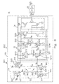
  • FIG. 3 is a schematic diagram showing a temperature compensating device 93 according to the first embodiment of the present invention.
  • the temperature compensating device 93 includes a temperature compensating circuit 931 and an output unit 33 .
  • the temperature compensating circuit 931 may be a temperature compensating configuration 9311 described as follows.
  • the temperature compensating configuration 9311 includes a reference circuit 31 and a first circuit 3 A, wherein the reference circuit 31 may be a reference current source circuit in an embodiment.
  • the reference circuit 31 has a reference current i 31 and includes a transistor 311 , a resistance circuit 312 and a transistor 313 .
  • a first terminal A 31 of the resistance circuit 312 receives the reference current i 31
  • the resistance circuit 312 includes a positive-temperature-coefficient resistor R 31 and a negative-temperature-coefficient resistor R 32 , wherein the positive-temperature-coefficient resistor R 31 , with a positive temperature coefficient, and the negative-temperature-coefficient resistor R 32 , with a negative temperature coefficient, form a series connection combination connected in series between a first terminal A 31 and a second terminal A 32 terminal of the resistance circuit 312 .
  • the transistor 311 includes an NMOS transistor 3111 .
  • the source S of the NMOS transistor 3111 is electrically connected to a ground potential GND.
  • the gate G of the NMOS transistor 3111 is electrically connected to the drain D of the NMOS transistor 3111 and the second terminal A 32 of the resistance circuit 312 .
  • the drain D of the NMOS transistor 3111 produces a bias-voltage signal V 31 .
  • the transistor 313 includes a PMOS transistor 3131 .
  • the source S of the PMOS transistor 3131 is electrically connected to a voltage source potential V DD ;
  • the gate G of the PMOS transistor 3131 receives a control signal V 32 ;
  • the drain D of the PMOS transistor 3131 is electrically connected to the first terminal A 31 of the resistance circuit 312 and produces the reference current i 31 .
  • the NMOS transistor 3111 may be a NPN transistor (not shown), and the PMOS transistor 3131 may be a PNP transistor (not shown), wherein the source S, the gate G and the drain D correspond to the emitter, the base and the collector of the BJT respectively, and the descriptions given below take the MOS-type transistors as examples.
  • the first circuit 3 A receives the bias-voltage signal V 31 , and produces an output signal V E9 in response to the bias-voltage signal V 31 , wherein the temperature compensating configuration 9311 utilizes the positive-temperature-coefficient resistor R 31 and the negative-temperature-coefficient resistor R 32 to compensate a variable frequency of the output signal V E9 for a temperature change in the temperature compensating configuration 9311 .
  • the first circuit 3 A may include a transistor 3211 that includes an NMOS transistor 32111 .
  • the gate G of the NMOS transistor 32111 receives the bias-voltage signal V 31 , and the drain D of the NMOS transistor 32111 produces a current I E1 , wherein the NMOS transistor 3111 and the NMOS transistor 32111 constitute a current mirror, and the current I E1 is proportional to the reference current i 31 and is a factor of producing the variable frequency of the output signal V E9 .
  • the first circuit 3 A may be a ring oscillator 32 .
  • the output signal V E9 of the ring oscillator 32 has an oscillation frequency f 3 being the variable frequency.
  • the oscillation frequency f 3 is compensated for the temperature change due to a compensation configuration including the positive-temperature-coefficient resistor R 31 and the negative-temperature-coefficient resistor R 32 .
  • the ring oscillator 32 includes odd-number stages of inverter circuits 321 , 322 , . . . and 329 , and each (such as 321 ) of the inverter circuits 321 , 322 , . . . and 329 includes the same structure, wherein the inverter circuit 329 produces the output signal V E9 fed back to the inverter circuit 321 .
  • the inverter circuit 321 receives the output signal V E9 and the bias-voltage signal V 31 , and produces an output signal V E1 in response to the output signal V E9 and the bias-voltage signal V 31 , wherein the output signal V E1 has a delay and an inversion in comparison with the output signal V E9 .
  • the inverter circuit 321 may includes a transistor 3211 , a transistor 3212 and a capacitor C 31 .
  • the transistor 3211 includes an NMOS transistor 32111 .
  • a first terminal W 31 of the capacitor C 31 is electrically connected to the drain D of the NMOS transistor 32111 .
  • a second terminal W 32 of the capacitor C 31 is electrically connected to the source S of the NMOS transistor 32111 .
  • a charging rate and a discharging rate of the capacitor C 31 are kept for the temperature change.
  • the transistor 3212 includes a PMOS transistor 32121 .
  • the gate G of the PMOS transistor 32121 receives the output signal V E9 , and the drain D of the PMOS transistor 32121 is electrically connected to the drain D of the NMOS transistor 32111 , and produces the output signal V E1 provided to the gate G of a PMOS transistor 32221 of the inverter circuit 322 .
  • the output unit 33 receives the output signal V E9 and an enable signal V 3A , and produces a clock signal CLK 3 , wherein the clock signal CLK 3 may have the oscillation frequency f 3 in an ideal state.
  • the temperature compensating circuit 931 may be a temperature compensating configuration 9312 described as follows.
  • the temperature compensating configuration 9312 includes a reference circuit 31 and a first circuit 3 A.
  • the reference circuit 31 e.g. a reference current source circuit, has a reference current i 31 , and includes a resistance circuit 312 and a transistor 311 .
  • the resistance circuit 312 includes a negative-temperature-coefficient resistor R 32 , wherein the first terminal A 31 of the resistance circuit 312 receives the reference current i 31 , and at least a first portion of the reference current i 31 flows through the negative temperature coefficient resistor R 32 .
  • a path P 3 disposed between the drain D and the source S of the transistor 311 is connected in series with the resistance circuit 312 , the gate G of the transistor 311 is electrically connected to the drain D of the transistor 311 and the second terminal A 32 of the resistance circuit 312 , and the drain D of the transistor 311 produces a bias-voltage signal V 31 .
  • the first circuit 3 A produces an output signal V E9 in response to the bias-voltage signal V 31 , wherein the temperature compensating configuration 9312 utilizes the negative-temperature-coefficient resistor R 32 to compensate the output signal V E9 for a temperature change in the temperature compensating configuration 9312 .
  • the temperature compensating circuit 931 may be a temperature compensating configuration 9313 described as follows.
  • the temperature compensating configuration 9313 includes a reference circuit 31 and a transistor 3211 .
  • the reference circuit 31 has a reference current i 31 , and includes a resistance circuit 312 and a transistor 311 .
  • the resistance circuit 312 includes at least a negative-temperature-coefficient resistor R 32 , wherein a first terminal A 31 of the resistance circuit 312 receives the reference current i 31 , and at least a portion of the reference current i 31 flows through the negative temperature coefficient resistor R 32 .
  • a path P 3 disposed between the drain D and the source S of the transistor 311 is connected in series with the resistance circuit 312 , the gate G of the transistor 311 is electrically connected to the drain D of the transistor 311 and the second terminal A 32 of the resistance circuit 312 .
  • the transistor 3211 is electrically connected to the transistor 311 ; e.g., the gate G of the transistor 3211 is electrically connected to the gate G of the transistor 311 .
  • the transistor 311 and the transistor 3211 constitute a current mirror; the drain D of the transistor 3211 produces a current I E1 ; the temperature compensating configuration 9313 utilizes the negative-temperature-coefficient resistor R 32 to compensate the current I E1 for a temperature change in the temperature compensating configuration 9313 .
  • the transistor 3211 may be disposed in a ring oscillator 32 having an oscillation frequency f 3 , and the oscillation frequency f 3 is compensated for the temperature change through a compensation of the current I E1 .
  • the resistance circuit 312 may further includes at least a positive-temperature-coefficient resistor R 31 , wherein at least a portion of the reference current i 31 flows through the positive-temperature-coefficient resistor R 31 , and a preset connection combination between the at least a negative-temperature-coefficient resistor R 32 and the at least a positive-temperature-coefficient resistor R 31 is established, so that the temperature compensating configuration 9313 utilizes the resistance circuit 312 to compensate the current I E1 for the temperature change.
  • FIG. 4( a ) is a schematic diagram showing the resistances Q 31 and Q 32 for a temperature change according to the first embodiment of the present invention
  • FIG. 4( b ) is a schematic diagram showing both the oscillation frequency f 3 and a resistance Q 3 for the temperature change according to the first embodiment of the present invention.
  • the curve Y 31 denotes the oscillation frequency f 3 for the temperature change.
  • the resistance Q 31 with a positive temperature coefficient
  • the resistance Q 32 with a negative temperature coefficient, adjust the resistance Q 3 of the resistance circuit 312 , which causes the reference circuit 31 to provide the reference current i 31 close in magnitude under different temperatures in the temperature compensating configuration 9311 . Therefore, all stages of the inverter circuits 321 , 322 , . . . and 329 in the ring oscillator 32 keep charging and discharging rates without change for the temperature change, which causes the oscillation frequency f 3 to not drift for the temperature change.
  • the resistance Q 31 of the positive-temperature-coefficient resistor R 31 can increases, but the resistance Q 31 of the negative-temperature-coefficient resistor R 32 can decrease.
  • the characteristic-coefficient ratio (a 3 :b 3 ) between the resistance Q 31 and the resistance Q 32 is adjusted according to the temperature property (in general, positive correlation to the temperature; i.e. the frequency decreases when the temperature increases) of the original circuit configuration (lack of the resistance Q 32 ) in order to adjust the reference current i 31 , flowing through the resistance Q 31 and the resistance Q 32 , and compensate the frequency drift produced in the ring oscillator 32 due to the temperature change. Therefore, the temperature compensating configuration 9311 can be applied to serve as the internal oscillator, the frequency of which does not drift for the temperature change.
  • FIG. 5 is a schematic diagram showing a temperature compensating device 94 according to the second embodiment of the present invention.
  • the temperature compensating device 94 includes a reference circuit 41 and a first circuit 4 A, wherein the reference circuit 31 may be a reference current source circuit in an embodiment.
  • the reference circuit 41 has a reference current i 41 and includes a transistor 411 , a resistance circuit 412 and a transistor 413 .
  • a first terminal A 41 of the resistance circuit 412 receives the reference current i 41
  • the resistance circuit 412 includes a positive-temperature-coefficient resistor R 41 and a negative-temperature-coefficient resistor R 42 , wherein the positive-temperature-coefficient resistor R 41 and the negative-temperature-coefficient resistor R 42 form a series connection combination connected in series between a first terminal A 41 and a second terminal A 42 of the resistance circuit 412 .
  • the positive-temperature-coefficient resistor R 41 and the negative-temperature-coefficient resistor R 42 form a parallel connection combination between the first terminal A 41 and the second terminal A 42 of the resistance circuit 412 .
  • the resistance circuit 412 includes at least a positive-temperature-coefficient resistor R 41 and at least a negative-temperature-coefficient resistor R 42 , wherein the at least a positive-temperature-coefficient resistor R 41 and the at least a negative-temperature-coefficient resistor R 42 are connected in series or parallel according to a preset connection combination.
  • the transistor 411 includes a PMOS transistor 4111 .
  • the source S of the PMOS transistor 4111 is electrically connected to a voltage source potential V DD .
  • the gate G of the PMOS transistor 4111 is electrically connected to the drain D of the PMOS transistor 4111 and the second terminal A 42 of the resistance circuit 412 .
  • the drain D of the PMOS transistor 4111 produces a bias-voltage signal V 41 .
  • the transistor 413 includes an NMOS transistor 4131 .
  • the source S of the NMOS transistor 4131 is electrically connected to a ground potential GND.
  • the gate G of the NMOS transistor 4131 receives a control signal V 42 ; the drain D of the NMOS transistor 4131 is electrically connected to the first terminal A 41 of the resistance circuit 412 and produces the reference current i 41 .
  • the first circuit 4 A produces an output signal V FA in response to the bias-voltage signal V 41 , wherein the temperature compensating device 94 utilizes the resistance circuit 412 to compensate a variable frequency of the output signal V FA for a temperature change in the temperature compensating device 94 .
  • the first circuit 4 A may include a ring oscillator 42 and an output unit 43 .
  • the ring oscillator 42 receives the bias-voltage signal V 41 , and produces an output signal V F9 having an oscillation frequency f 4 in response to the bias-voltage signal V 41 .
  • the output unit 43 receives the output signal V F9 and an enable signal V 4A , and produces the output signal V FA , wherein the output signal V FA is a clock signal CLK 4 having an output frequency f 41 .
  • the temperature compensating device 94 utilizes the resistance circuit 412 to compensate the output frequency f 41 being the variable frequency for a temperature change in the temperature compensating device 94 .
  • the ring oscillator 42 includes odd-number stages of inverter circuits 421 , 422 , . . . and 429 , and each (such as 421 ) of the inverter circuits 421 , 422 , . . . and 429 includes the same structure, wherein the inverter circuit 429 produces the output signal V F9 fed back to the inverter circuit 421 .
  • the inverter circuit 421 may includes a transistor 4211 , a transistor 4212 and a capacitor C 41 .
  • the transistor 4211 includes a PMOS transistor 42111 .
  • the gate of the PMOS transistor 42111 receives the bias-voltage signal V 41 , and the drain D of the PMOS transistor 42111 produces a current I F1 , wherein the PMOS transistor 4111 and the PMOS transistor 42111 constitute a current mirror, and the current I F1 is proportional to the reference current i 41 .
  • the transistor 4212 includes an NMOS transistor 42121 .
  • the gate G of the NMOS transistor 42121 receives the output signal V F9 , and the drain D of the NMOS transistor 42121 is electrically connected to the drain D of the PMOS transistor 42111 .
  • a first terminal W 41 of the capacitor C 41 is electrically connected to the drain D of the NMOS transistor 42121 .
  • a second terminal W 42 of the capacitor C 41 is electrically connected to the source S of the NMOS transistor 42121 .
  • the drain D of the NMOS transistor 42121 produces the output signal V F1 provided to the gate G of an NMOS transistor 42221 of the inverter circuit 422 .
  • FIG. 6 is a schematic diagram showing a temperature compensating device 95 according to the third embodiment of the present invention.
  • the temperature compensating device 95 includes a temperature compensating circuit 951 and an output unit 53 .
  • the temperature compensating circuit 951 may be a temperature compensating configuration 9511 described as follows.
  • the temperature compensating configuration 9511 includes a reference circuit 51 and a first circuit 5 A.
  • the reference circuit 51 has a reference current i 51 and includes plural transistors 511 , 513 , 514 , and 515 and a resistance circuit 512 .
  • a first terminal A 51 of the resistance circuit 512 receives the reference current i 51
  • the resistance circuit 512 includes a positive-temperature-coefficient resistor R 51 and a negative-temperature-coefficient resistor R 52 , wherein the positive-temperature-coefficient resistor R 51 and the negative-temperature-coefficient resistor R 52 form a series connection combination connected in series between the first terminal A 51 and a second terminal A 32 of the resistance circuit 512 .
  • the transistor 511 includes an NMOS transistor 5111 .
  • the source S of the NMOS transistor 5111 is electrically connected to a ground potential GND.
  • the gate G of the NMOS transistor 5111 is electrically connected to the drain D of the NMOS transistor 5111 and the second terminal A 52 of the resistance circuit 512 .
  • the drain D of the NMOS transistor 5111 produces a bias-voltage signal V 51 .
  • the transistor 513 includes a PMOS transistor 5131 .
  • the source S of the PMOS transistor 5131 is electrically connected to a voltage source potential V DD ;
  • the gate G of the PMOS transistor 5131 receives a control signal V 52 ;
  • the drain D of the PMOS transistor 5131 is electrically connected to the first terminal A 51 of the resistance circuit 512 and produces the reference current i 51 .
  • the transistor 514 includes an NMOS transistor 5141 .
  • the gate G of the NMOS transistor 5141 receives the bias-voltage signal V 51 , and the drain D of the NMOS transistor 5141 produces a current i 52 , wherein the NMOS transistor 5111 and the NMOS transistor 5141 constitute a current mirror, and the current i 52 is proportional to the reference current i 51 .
  • the transistor 515 includes a PMOS transistor 5151 .
  • the drain D of the PMOS transistor 5151 is electrically connected to the gate G of the PMOS transistor 5151 and the drain D of the NMOS transistor 5141 . Besides, the drain D of the PMOS transistor 5151 produces a bias-voltage signal V 53 .
  • the first circuit 5 A receives the bias-voltage signal V 51 and the bias-voltage signal V 53 , and produces an output signal V G9 in response to the bias-voltage signal V 51 and the bias-voltage signal V 51 , wherein the temperature compensating configuration 9511 utilizes the positive-temperature-coefficient resistor R 51 and the negative-temperature-coefficient resistor R 52 to compensate a variable frequency of the output signal V G9 for a temperature change in the temperature compensating configuration 9511 .
  • the first circuit 5 A may include a transistor 5211 and a transistor 5212 .
  • the transistor 5211 includes an NMOS transistor 52111 .
  • the gate G of the NMOS transistor 52111 receives the bias-voltage signal V 51 , and the drain D of the NMOS transistor 52111 produces a current I G1 , wherein the NMOS transistor 5111 and the NMOS transistor 52111 constitute a current mirror, and the current I G1 is proportional to the reference current i 51 and is a first factor of producing the variable frequency of the output signal V G9 .
  • the transistor 5212 includes a PMOS transistor 52121 .
  • the gate G of the PMOS transistor 52121 receives the bias-voltage signal V 53 , and the drain D of the PMOS transistor 52121 produces a current I G2 , wherein the PMOS transistor 5151 and the PMOS transistor 52121 constitute a current mirror, and the current I G2 is proportional to the current i 52 and is a second factor of producing the variable frequency of the output signal V G9 .
  • the first circuit 5 A may be a ring oscillator 52 .
  • the output signal V G9 of the ring oscillator 52 has an oscillation frequency f 5 being the variable frequency.
  • the oscillation frequency f 5 is compensated for the temperature change due to a compensation configuration including the positive-temperature-coefficient resistor R 51 and the negative-temperature-coefficient resistor R 52 .
  • the ring oscillator 52 includes odd-number stages of inverter circuits 521 , 522 , . . . and 529 , and each (such as 521 ) of the inverter circuits 521 , 522 , . . . and 529 includes the same structure, wherein the inverter circuit 529 produces the output signal V G9 fed back to the inverter circuit 521 .
  • the inverter circuit 521 receives the output signal V G9 , the bias-voltage signal V 51 and the bias-voltage signal V 53 , and produces an output signal V G1 in response to the output signal V G9 , the bias-voltage signal V 51 and the bias-voltage signal V 53 , wherein the output signal V G1 has a delay and an inversion in comparison with the output signal V G9 .
  • the inverter circuit 521 may includes plural transistors 5211 , 5212 , 5213 and 5214 , a capacitor C 51 and an NOT gate 5215 .
  • a first terminal W 51 of the capacitor C 51 is electrically connected to the drain D of the NMOS transistor 52111 .
  • a second terminal W 52 of the capacitor C 51 is electrically connected to the source S of the NMOS transistor 52111 .
  • a charging rate and a discharging rate of the capacitor C 51 are kept for the temperature change.
  • the transistor 5213 includes a PMOS transistor 52131 .
  • the gate G of the PMOS transistor 52131 receives the output signal V G9 , and the drain D of the PMOS transistor 52131 is electrically connected to the drain D of the NMOS transistor 52111 .
  • the transistor 5214 includes an NMOS transistor 52141 .
  • the gate G of the NMOS transistor 52141 is electrically connected to the drain D of the NMOS transistor 52111 , the source S of the NMOS transistor 52141 is electrically connected to the source S of the NMOS transistor 52111 , and the drain D of the NMOS transistor 52141 is electrically connected to the drain D of the PMOS transistor 52121 .
  • the input terminal of the NOT gate 5215 is electrically connected to the drain D of the PMOS transistor 52121 , and the output terminal of the NOT gate 5215 produces the output signal V G1 provided to the gate G of a PMOS transistor 52231 of the inverter circuit 522 .
  • the output unit 53 receives the output signal V G9 and produces a clock signal CLK 5 , wherein the clock signal CLK 5 may have the oscillation frequency f 3 in an ideal state.
  • the temperature compensating circuit 951 may be a temperature compensating configuration 9512 described as follows.
  • the temperature compensating configuration 9512 includes a reference circuit 51 and a first circuit 5 A.
  • the reference circuit 51 has a reference current i 51 and includes a resistance circuit 512 and plural transistor 511 , 514 and 515 .
  • the resistance circuit 512 includes a negative-temperature-coefficient resistor R 52 , wherein a first terminal A 51 of the resistance circuit 512 receives the reference current i 51 and at least a first portion of the reference current i 51 flows through the negative temperature coefficient resistor R 52 .
  • a path P 5 disposed between the drain D and the source S of the transistor 511 is connected in series with the resistance circuit 512 , the gate G of the transistor 511 is electrically connected to the drain D of the transistor 511 and a second terminal A 52 of the resistance circuit 512 , and the drain D of the transistor 511 produces a bias-voltage signal V 51 .
  • the gate G of the transistor 514 receives the bias-voltage signal V 51 , and the drain D of the transistor 514 produces a current i 52 , wherein the transistor 511 and the transistor 514 constitute a current mirror, and the current i 52 is proportional to the reference current i 51 .
  • the drain D of the transistor 515 is electrically connected to the gate G of the transistor 515 , and the drain D of the transistor 515 produces a bias-voltage signal V 53 .
  • the first circuit 5 A produces an output signal V G9 in response to the bias-voltage signal V 51 and the bias-voltage signal V 53 , wherein the temperature compensating configuration 9512 utilizes the negative-temperature-coefficient resistor R 52 to compensate the output signal V G9 for a temperature change in the temperature compensating configuration 9512 .
  • FIG. 7 is a schematic diagram showing a temperature compensating device 96 according to the fourth embodiment of the present invention.
  • the temperature compensating device 96 includes a reference circuit 51 and a first circuit 6 A.
  • the reference circuit 61 has a reference current i 61 and includes plural transistors 611 , 613 , 614 , and 615 and a resistance circuit 612 .
  • a first terminal A 61 of the resistance circuit 612 receives the reference current i 61
  • the resistance circuit 612 includes a positive-temperature-coefficient resistor R 61 and a negative-temperature-coefficient resistor R 62 , wherein the positive-temperature-coefficient resistor R 61 and the negative-temperature-coefficient resistor R 62 form a series connection combination connected in series between the first terminal A 61 and a second terminal A 62 of the resistance circuit 612 .
  • the transistor 611 includes a PMOS transistor 6111 .
  • the source S of the PMOS transistor 6111 is electrically connected to a voltage source potential V DD .
  • the gate G of the PMOS transistor 6111 is electrically connected to the drain D of the PMOS transistor 6111 and the second terminal A 62 of the resistance circuit 612 .
  • the drain D of the PMOS transistor 6111 produces a bias-voltage signal V 61 .
  • the transistor 613 includes an NMOS transistor 6131 .
  • the source S of the NMOS transistor 6131 is electrically connected to a ground potential GND; the gate G of the NMOS transistor 6131 receives a control signal V 62 ; the drain D of the NMOS transistor 6131 is electrically connected to the first terminal A 61 of the resistance circuit 612 and produces the reference current i 61 .
  • the transistor 614 includes a PMOS transistor 6141 .
  • the gate G of the PMOS transistor 6141 receives the bias-voltage signal V 61 , and the drain D of the PMOS transistor 6141 produces a current i 62 , wherein the PMOS transistor 6111 and the PMOS transistor 6141 constitute a current mirror, and the current i 62 is proportional to the reference current i 61 .
  • the transistor 615 includes an NMOS transistor 6151 .
  • the drain D of the NMOS transistor 6151 is electrically connected to the gate G of the NMOS transistor 6151 and the drain D of the PMOS transistor 6141 .
  • the drain D of the NMOS transistor 6151 produces a bias-voltage signal V 63 .
  • the first circuit 6 A receives the bias-voltage signal V 61 and the bias-voltage signal V 63 , and produces an output signal V HA in response to the bias-voltage signal V 61 and the bias-voltage signal V 63 , wherein the temperature compensating device 96 utilizes the resistance circuit 612 to compensate a variable frequency of the output signal V HA for a temperature change in the temperature compensating device 96 .
  • the first circuit 6 A may include a ring oscillator 62 and an output unit 63 .
  • the ring oscillator 62 receives the bias-voltage signal V 61 and the bias-voltage signal V 63 , and produces an output signal V H9 having an oscillation frequency f 6 in response to the bias-voltage signal V 61 and the bias-voltage signal V 63 .
  • the ring oscillator 62 includes odd-number stages of inverter circuits 621 , 622 , . . . and 629 , and each (such as 621 ) of the inverter circuits 621 , 622 , . . . and 629 includes the same structure, wherein the inverter circuit 629 produces the output signal V H9 fed back to the inverter circuit 621 .
  • the inverter circuit 621 may includes plural transistors 6211 , 6212 , 6213 and 6214 , a capacitor C 61 and an NOT gate 6215 .
  • the transistor 6211 includes an NMOS transistor 62111 .
  • the gate of the NMOS transistor 62111 receives the bias-voltage signal V 63 , and the drain D of the NMOS transistor 62111 produces a current I H1 , wherein the NMOS transistor 6151 and the NMOS transistor 62111 constitute a current mirror, and the current I H1 is proportional to the current i 62 and is a first factor of producing the variable frequency of the output signal V HA .
  • the transistor 6212 includes a PMOS transistor 62121 .
  • the gate G of the PMOS transistor 62121 receives the bias-voltage signal V 61 , and the drain D of the PMOS transistor 62121 produces a current I H2 , wherein the PMOS transistor 6111 and the PMOS transistor 62121 constitute a current mirror, and the current I H2 is proportional to the reference current i 61 and is a second factor of producing the variable frequency of the output signal V HA .
  • a first terminal W 61 of the capacitor C 61 is electrically connected to the drain D of the NMOS transistor 62111 .
  • a second terminal W 62 of the capacitor C 61 is electrically connected to the source S of the NMOS transistor 62111 .
  • the transistor 6213 includes a PMOS transistor 62131 .
  • the gate G of the PMOS transistor 62131 receives the output signal V H9 , and the drain D of the PMOS transistor 62131 is electrically connected to the drain D of the NMOS transistor 62111 .
  • the transistor 6214 includes an NMOS transistor 62141 .
  • the gate G of the NMOS transistor 62141 is electrically connected to the drain D of the NMOS transistor 62111
  • the source S of the NMOS transistor 52141 is electrically connected to the source S of the NMOS transistor 62111
  • the drain D of the NMOS transistor 62141 is electrically connected to the drain D of the PMOS transistor 62121 .
  • the input terminal of the NOT gate 6215 is electrically connected to the drain D of the PMOS transistor 62121
  • the output terminal of the NOT gate 6215 produces the output signal V H1 provided to the gate G of a PMOS transistor 62231 of the inverter circuit 622 .
  • the output unit 63 receives the output signal V H9 and produces the output signal V HA , wherein the output signal V HA is a clock signal CLK 6 having an output frequency f 61 .
  • the temperature compensating device 96 utilizes the resistance circuit 612 to compensate the output frequency f 61 being the variable frequency for the temperature change.
  • the output unit 63 includes an NOT gate 631 and an NOT gate 632 connected in series with the NOT gate 631 .
  • the temperature compensating method includes the following steps.
  • a reference current i 31 is converted into a first bias-voltage signal V 31 by a resistance circuit 312 and a transistor 311 , wherein the resistance circuit 312 has a first terminal A 31 receiving the reference current i 31 , a second terminal A 32 and a negative-temperature-coefficient resistor R 32 , the transistor 311 has a drain D, a source S, a gate G and a path P 3 disposed between the drain D and the source S of the transistor 311 , the path P 3 of the transistor 311 is connected in series with the resistance circuit 312 , and the gate G of the transistor 311 is electrically connected to the drain D of the transistor 311 and the second terminal A 32 of the resistance circuit 312 .
  • An output signal V E9 having a variable frequency is produced in response to the bias-voltage signal V E9 .
  • the negative-temperature-coefficient resistor R 32 is produced in response to the bias-voltage signal V E9 .

Landscapes

  • Engineering & Computer Science (AREA)
  • Microelectronics & Electronic Packaging (AREA)
  • Physics & Mathematics (AREA)
  • Nonlinear Science (AREA)
  • Electromagnetism (AREA)
  • General Physics & Mathematics (AREA)
  • Radar, Positioning & Navigation (AREA)
  • Automation & Control Theory (AREA)
  • Logic Circuits (AREA)
  • Oscillators With Electromechanical Resonators (AREA)
  • Inductance-Capacitance Distribution Constants And Capacitance-Resistance Oscillators (AREA)

Abstract

A temperature compensating circuit including a reference circuit, a transistor and a first circuit is provided. The reference circuit has a reference current and a resistance circuit, wherein the resistance circuit includes a first terminal receiving the reference current, a second terminal and a negative-temperature-coefficient resistor. The transistor has a drain, a source and a path disposed between the drain and the source, wherein the path of the transistor is connected in series with the resistance circuit, a gate of the transistor is electrically connected to the drain of the transistor and the second terminal of the resistance circuit, and the drain of the transistor produces a bias-voltage signal. The first circuit produces an output signal having a variable frequency in response to the bias-voltage signal, wherein the temperature compensating circuit utilizes the negative-temperature-coefficient resistor to compensate the variable frequency for a temperature change in the temperature compensating circuit.

Description

FIELD OF THE INVENTION
The present invention relates to a temperature compensating circuit and method, and more particularly to a temperature compensating circuit and method for compensating an oscillation frequency of an oscillator for a temperature change.
BACKGROUND OF THE INVENTION
An internal oscillator is usually used in the integrated circuit for providing a system clock. However, because the components and the wires in the internal oscillator all have temperature properties, the frequency of the internal oscillator changes once the operating temperature changes.
A ring oscillator is usually served as a constituent circuit of the internal oscillator. Because the MOS device has the property of the positive temperature coefficient in itself, the frequency of the ring oscillator has the following properties when the temperature changes. When the temperature increases, the frequency become lower because of an increment of the internal resistance of the MOS device. Conversely, when the temperature decreases, the frequency become faster.
Please refer to FIG. 1, which is a schematic diagram showing a conventional internal oscillator 10. As shown, the internal oscillator 10 includes a ring oscillator 12 and an output unit 13. The ring oscillator 12 includes odd-number stages of inverter circuits 121, 122, 123, . . . , 128 and 129. An output terminal K9 of the ring oscillator 12 is electrically connected to an input terminal K0 of the inverter circuit 121, which causes an output signal VA9 of the ring oscillator 12 to be fed back to the input terminal K0 of the inverter circuit 121. Besides, an input terminal KA of the inverter circuit 121 receives an enable signal EN.
An output signal VA1 of the inverter circuit 121 has a delay and an inversion in comparison with the output signal VA9 of the inverter circuit 129. An output signal VA2 of the inverter circuit 122 has a delay and an inversion in comparison with the output signal VA1 of the inverter circuit 121. Similar scheme is applicable to two output signals of every two adjacent stages. Therefore, the output signal VA9 of the ring oscillator 12 has an oscillation frequency f1.
The output unit 13 includes two NOT gates connected in series, receives the output signal VA9, and produces a clock signal CLK1, wherein the clock signal CLK1 may have the oscillation frequency f1 in an ideal state.
Please refer to FIG. 2( a), which is a schematic diagram showing another conventional internal oscillator 20. As shown, the internal oscillator 20 includes a reference circuit 21, a ring oscillator 22 and an output unit 23. The reference circuit 21 includes an NMOS transistor 211, a resistor R2 with a positive temperature coefficient, and a PMOS transistor 213. A gate G of the PMOS transistor 213 receives a control signal V22, and a reference current i21 flows through the PMOS transistor 213, the resistor R2 and the NMOS transistor 211.
The ring oscillator 22 includes odd-number stages of inverter circuits 221, 222, 223, . . . , 228 and 229, and each (such as 221) of the inverter circuits 221, 222, 223, . . . , 228 and 229 includes the same structure. The ring oscillator 22 produces an output signal VB9 having an oscillation frequency f2. The inverter circuit 221 includes an NMOS transistor 2211, a PMOS transistor 2212 and a capacitor C21, and produces an output signal VB1. The output signal VB9 of the ring oscillator 22 is fed back to a gate of the PMOS transistor 2212. In order to achieve the required oscillation frequency f2 in a smaller amount of stages, a capacitor (e.g. C21) is added to each inverter (e.g. 221) for increasing a delay time between every two sequential stages of inverters.
The NMOS transistor 211 of the reference circuit 21 and an NMOS transistor (e.g. 2211) of each inverter (e.g. 221) constitute a current mirror. Therefore, plural currents i21, IB1, IB2, IB9 have a relation of i21=n*IB1=n*IB2=n*IB9, wherein n is a proportional coefficient. The reference circuit 21 controls a current (e.g. IB1), flowing in the each inverter (e.g. 221), to reach that the current is less influenced from the voltage drift. Besides, the reference current source circuit 21 utilizes the resistor R2 to adjust the oscillation frequency f2 of the ring oscillator 22.
The output unit 23 includes an NAND gate 231 ant an NOT gate 232. An input terminal M1 of the NAND gate 231 receives the output signal VA9. An input terminal M2 of the NAND gate 231 receives an enable signal V2A. The NOT gate 232 produces a clock signal CLK2, wherein the clock signal CLK2 may have the oscillation frequency f2 in an ideal state.
The common MOS device or the resistor R2 used in the reference circuit 21 mostly exhibits the property with a positive temperature coefficient in the semiconductor manufacturing process; i.e., the higher the temperature, the larger the resistance effect thereof, and the smaller on the contrary. Therefore, this property can cause the currents, flowing through various devices, to decrease when the temperature increases.
From the formula Q=CV=IT for the electric charge and the formula F=1/T for the frequency, a formula F=I/CV=1/RC is obtained, wherein the symbols C, V, T and R denote the capacitance, the voltage, the period and the resistance respectively. Please refer to FIG. 2( b), which is a schematic diagram showing both an oscillation frequency and a resistance for a temperature change in the internal oscillator in FIG. 2( a). As shown, the curve U21 denotes the resistance Q2 for the temperature change, and the curve Y21 denotes the oscillation frequency f2 for the temperature change. The oscillation frequency f2 decreases when the resistance Q2 increases; conversely, the oscillation frequency f2 increases when the resistance Q2 decreases.
In order that the reference current close in magnitude can be provided in different temperatures, which causes each stage of the oscillator to keep the charge and the discharge rates without change for the temperature change, to achieve the object that the oscillation frequency does not drift for the temperature change, a more effective temperature compensating circuit is demanded.
SUMMARY OF THE INVENTION
It is an object of the present invention to provide a temperature compensating circuit and method. A connection combination established between a negative-temperature-coefficient resistor and a positive-temperature-coefficient resistor is utilized to provide a reference current close in magnitude, which causes all stages of the oscillator to keep charging and discharging rates without change for the temperature change, so as to accomplish the effect of compensating the oscillation frequency in the temperature compensating circuit.
It is therefore the first aspect of the present invention to provide a temperature compensating circuit including a reference circuit, a first transistor and a second transistor. The reference circuit has a reference current and a resistance circuit, wherein the resistance circuit has a first terminal receiving the reference current, a second terminal and a negative-temperature-coefficient resistor, and at least a first portion of the reference current flows through the negative temperature coefficient resistor. The first transistor has a drain, a source, a gate and a path disposed between the drain and the source, wherein the path of the first transistor is connected in series with the resistance circuit, and the gate of the first transistor is electrically connected to the drain of the first transistor and the second terminal of the resistance circuit. The second transistor is electrically connected to the first transistor and has a drain, wherein the first and the second transistors constitute a current mirror, the drain of the second transistor produces a first current, and the temperature compensating circuit utilizes the negative-temperature-coefficient resistor to compensate the first current for a temperature change in the temperature compensating circuit.
It is therefore the second aspect of the present invention to provide a temperature compensating circuit including a reference circuit, a first transistor and a first circuit. The reference circuit has a reference current and a resistance circuit, wherein the resistance circuit includes a first terminal receiving the reference current, a second terminal and a negative-temperature-coefficient resistor. The first transistor has a drain, a source, a gate and a path disposed between the drain and the source, wherein the path of the first transistor is connected in series with the resistance circuit, the gate of the first transistor is electrically connected to the drain of the first transistor and the second terminal of the resistance circuit, and the drain of the first transistor produces a first bias-voltage signal. The first circuit produces a first output signal having a variable frequency in response to the first bias-voltage signal, wherein the temperature compensating circuit utilizes the negative-temperature-coefficient resistor to compensate the variable frequency of the first output signal for a temperature change in the temperature compensating circuit.
It is therefore the third aspect of the present invention to provide a temperature compensating method. The method includes the following steps. A reference current converted into a first bias-voltage signal by a resistance circuit and a first transistor, wherein the resistance circuit has a first terminal receiving the reference current, a second terminal and a negative-temperature-coefficient resistor, the first transistor has a drain, a source, a gate and a path disposed between the drain and the source, the path of the first transistor is connected in series with the resistance circuit, and the gate of the first transistor is electrically connected to the drain of the first transistor and the second terminal of the resistance circuit. A first output signal having a variable frequency is produced in response to the first bias-voltage signal. In addition, the negative-temperature-coefficient resistor is utilized to compensate the variable frequency of the first output signal for a temperature change.
BRIEF DESCRIPTION OF THE DRAWINGS
The foregoing and other features and advantages of the present invention will be more clearly understood through the following descriptions with reference to the drawings, wherein:
FIG. 1 is a schematic diagram showing a conventional internal oscillator;
FIG. 2( a) is a schematic diagram showing another conventional internal oscillator;
FIG. 2( b) is a schematic diagram showing both an oscillation frequency and a resistance for a temperature change in the internal oscillator in FIG. 2( a);
FIG. 3 is a schematic diagram showing a temperature compensating device according to the first embodiment of the present invention;
FIG. 4( a) is a schematic diagram showing resistances for a temperature change according to the first embodiment of the present invention;
FIG. 4( b) is a schematic diagram showing both an oscillation frequency and a resistance for the temperature change according to the first embodiment of the present invention;
FIG. 5 is a schematic diagram showing a temperature compensating device according to the second embodiment of the present invention;
FIG. 6 is a schematic diagram showing a temperature compensating device according to the third embodiment of the present invention; and
FIG. 7 is a schematic diagram showing a temperature compensating device according to the fourth embodiment of the present invention.
DETAIL DESCRIPTION OF THE PREFERRED EMBODIMENT
The present invention will now be described more specifically with reference to the following embodiments. It is to be noted that the following descriptions of preferred embodiments of this invention are presented herein for the purposes of illustration and description only; it is not intended to be exhaustive or to be limited to the precise form disclosed.
Please refer to FIG. 3, which is a schematic diagram showing a temperature compensating device 93 according to the first embodiment of the present invention. As shown, the temperature compensating device 93 includes a temperature compensating circuit 931 and an output unit 33.
The temperature compensating circuit 931 may be a temperature compensating configuration 9311 described as follows. The temperature compensating configuration 9311 includes a reference circuit 31 and a first circuit 3A, wherein the reference circuit 31 may be a reference current source circuit in an embodiment. The reference circuit 31 has a reference current i31 and includes a transistor 311, a resistance circuit 312 and a transistor 313.
A first terminal A31 of the resistance circuit 312 receives the reference current i31, and the resistance circuit 312 includes a positive-temperature-coefficient resistor R31 and a negative-temperature-coefficient resistor R32, wherein the positive-temperature-coefficient resistor R31, with a positive temperature coefficient, and the negative-temperature-coefficient resistor R32, with a negative temperature coefficient, form a series connection combination connected in series between a first terminal A31 and a second terminal A32 terminal of the resistance circuit 312.
The transistor 311 includes an NMOS transistor 3111. The source S of the NMOS transistor 3111 is electrically connected to a ground potential GND. The gate G of the NMOS transistor 3111 is electrically connected to the drain D of the NMOS transistor 3111 and the second terminal A32 of the resistance circuit 312. Besides, the drain D of the NMOS transistor 3111 produces a bias-voltage signal V31.
The transistor 313 includes a PMOS transistor 3131. The source S of the PMOS transistor 3131 is electrically connected to a voltage source potential VDD; the gate G of the PMOS transistor 3131 receives a control signal V32; the drain D of the PMOS transistor 3131 is electrically connected to the first terminal A31 of the resistance circuit 312 and produces the reference current i31. In a system of the bipolar junction transistor (BJT), the NMOS transistor 3111 may be a NPN transistor (not shown), and the PMOS transistor 3131 may be a PNP transistor (not shown), wherein the source S, the gate G and the drain D correspond to the emitter, the base and the collector of the BJT respectively, and the descriptions given below take the MOS-type transistors as examples.
The first circuit 3A receives the bias-voltage signal V31, and produces an output signal VE9 in response to the bias-voltage signal V31, wherein the temperature compensating configuration 9311 utilizes the positive-temperature-coefficient resistor R31 and the negative-temperature-coefficient resistor R32 to compensate a variable frequency of the output signal VE9 for a temperature change in the temperature compensating configuration 9311.
The first circuit 3A may include a transistor 3211 that includes an NMOS transistor 32111. The gate G of the NMOS transistor 32111 receives the bias-voltage signal V31, and the drain D of the NMOS transistor 32111 produces a current IE1, wherein the NMOS transistor 3111 and the NMOS transistor 32111 constitute a current mirror, and the current IE1 is proportional to the reference current i31 and is a factor of producing the variable frequency of the output signal VE9.
The first circuit 3A may be a ring oscillator 32. The output signal VE9 of the ring oscillator 32 has an oscillation frequency f3 being the variable frequency. The oscillation frequency f3 is compensated for the temperature change due to a compensation configuration including the positive-temperature-coefficient resistor R31 and the negative-temperature-coefficient resistor R32. The ring oscillator 32 includes odd-number stages of inverter circuits 321, 322, . . . and 329, and each (such as 321) of the inverter circuits 321, 322, . . . and 329 includes the same structure, wherein the inverter circuit 329 produces the output signal VE9 fed back to the inverter circuit 321.
The inverter circuit 321 receives the output signal VE9 and the bias-voltage signal V31, and produces an output signal VE1 in response to the output signal VE9 and the bias-voltage signal V31, wherein the output signal VE1 has a delay and an inversion in comparison with the output signal VE9. The inverter circuit 321 may includes a transistor 3211, a transistor 3212 and a capacitor C31. The transistor 3211 includes an NMOS transistor 32111. A first terminal W31 of the capacitor C31 is electrically connected to the drain D of the NMOS transistor 32111. A second terminal W32 of the capacitor C31 is electrically connected to the source S of the NMOS transistor 32111. A charging rate and a discharging rate of the capacitor C31 are kept for the temperature change.
The transistor 3212 includes a PMOS transistor 32121. The gate G of the PMOS transistor 32121 receives the output signal VE9, and the drain D of the PMOS transistor 32121 is electrically connected to the drain D of the NMOS transistor 32111, and produces the output signal VE1 provided to the gate G of a PMOS transistor 32221 of the inverter circuit 322. The output unit 33 receives the output signal VE9 and an enable signal V3A, and produces a clock signal CLK3, wherein the clock signal CLK3 may have the oscillation frequency f3 in an ideal state.
The temperature compensating circuit 931 may be a temperature compensating configuration 9312 described as follows. The temperature compensating configuration 9312 includes a reference circuit 31 and a first circuit 3A. The reference circuit 31, e.g. a reference current source circuit, has a reference current i31, and includes a resistance circuit 312 and a transistor 311. The resistance circuit 312 includes a negative-temperature-coefficient resistor R32, wherein the first terminal A31 of the resistance circuit 312 receives the reference current i31, and at least a first portion of the reference current i31 flows through the negative temperature coefficient resistor R32.
A path P3 disposed between the drain D and the source S of the transistor 311 is connected in series with the resistance circuit 312, the gate G of the transistor 311 is electrically connected to the drain D of the transistor 311 and the second terminal A32 of the resistance circuit 312, and the drain D of the transistor 311 produces a bias-voltage signal V31. The first circuit 3A produces an output signal VE9 in response to the bias-voltage signal V31, wherein the temperature compensating configuration 9312 utilizes the negative-temperature-coefficient resistor R32 to compensate the output signal VE9 for a temperature change in the temperature compensating configuration 9312.
The temperature compensating circuit 931 may be a temperature compensating configuration 9313 described as follows. The temperature compensating configuration 9313 includes a reference circuit 31 and a transistor 3211. The reference circuit 31 has a reference current i31, and includes a resistance circuit 312 and a transistor 311. The resistance circuit 312 includes at least a negative-temperature-coefficient resistor R32, wherein a first terminal A31 of the resistance circuit 312 receives the reference current i31, and at least a portion of the reference current i31 flows through the negative temperature coefficient resistor R32.
A path P3 disposed between the drain D and the source S of the transistor 311 is connected in series with the resistance circuit 312, the gate G of the transistor 311 is electrically connected to the drain D of the transistor 311 and the second terminal A32 of the resistance circuit 312. The transistor 3211 is electrically connected to the transistor 311; e.g., the gate G of the transistor 3211 is electrically connected to the gate G of the transistor 311. The transistor 311 and the transistor 3211 constitute a current mirror; the drain D of the transistor 3211 produces a current IE1; the temperature compensating configuration 9313 utilizes the negative-temperature-coefficient resistor R32 to compensate the current IE1 for a temperature change in the temperature compensating configuration 9313.
The transistor 3211 may be disposed in a ring oscillator 32 having an oscillation frequency f3, and the oscillation frequency f3 is compensated for the temperature change through a compensation of the current IE1. The resistance circuit 312 may further includes at least a positive-temperature-coefficient resistor R31, wherein at least a portion of the reference current i31 flows through the positive-temperature-coefficient resistor R31, and a preset connection combination between the at least a negative-temperature-coefficient resistor R32 and the at least a positive-temperature-coefficient resistor R31 is established, so that the temperature compensating configuration 9313 utilizes the resistance circuit 312 to compensate the current IE1 for the temperature change.
Please refer to FIG. 4( a) and FIG. 4( b); FIG. 4( a) is a schematic diagram showing the resistances Q31 and Q32 for a temperature change according to the first embodiment of the present invention; FIG. 4( b) is a schematic diagram showing both the oscillation frequency f3 and a resistance Q3 for the temperature change according to the first embodiment of the present invention. As shown, FIG. 4( a) and FIG. 4( b) are in a state of the temperature compensating configuration 9311; the curve U31 denotes the resistance Q31 (=a3*Q3A) of the positive-temperature-coefficient resistor R31 for the temperature change in the temperature compensating configuration 9311; the curve U32 denotes the resistance Q32 (=b3*Q3B) of the negative-temperature-coefficient resistor R32 for the temperature change; the curve U33 denotes the resistance Q3 (=a3*Q3A+b3*Q3B) of the resistance circuit 312 for the temperature change; the curve Y31 denotes the oscillation frequency f3 for the temperature change.
The resistance Q31, with a positive temperature coefficient, and the resistance Q32, with a negative temperature coefficient, adjust the resistance Q3 of the resistance circuit 312, which causes the reference circuit 31 to provide the reference current i31 close in magnitude under different temperatures in the temperature compensating configuration 9311. Therefore, all stages of the inverter circuits 321, 322, . . . and 329 in the ring oscillator 32 keep charging and discharging rates without change for the temperature change, which causes the oscillation frequency f3 to not drift for the temperature change.
When the temperature increases, the resistance Q31 of the positive-temperature-coefficient resistor R31 can increases, but the resistance Q31 of the negative-temperature-coefficient resistor R32 can decrease. The characteristic-coefficient ratio (a3:b3) between the resistance Q31 and the resistance Q32 is adjusted according to the temperature property (in general, positive correlation to the temperature; i.e. the frequency decreases when the temperature increases) of the original circuit configuration (lack of the resistance Q32) in order to adjust the reference current i31, flowing through the resistance Q31 and the resistance Q32, and compensate the frequency drift produced in the ring oscillator 32 due to the temperature change. Therefore, the temperature compensating configuration 9311 can be applied to serve as the internal oscillator, the frequency of which does not drift for the temperature change.
Please refer to FIG. 5, which is a schematic diagram showing a temperature compensating device 94 according to the second embodiment of the present invention. As shown, the temperature compensating device 94 includes a reference circuit 41 and a first circuit 4A, wherein the reference circuit 31 may be a reference current source circuit in an embodiment. The reference circuit 41 has a reference current i41 and includes a transistor 411, a resistance circuit 412 and a transistor 413.
A first terminal A41 of the resistance circuit 412 receives the reference current i41, and the resistance circuit 412 includes a positive-temperature-coefficient resistor R41 and a negative-temperature-coefficient resistor R42, wherein the positive-temperature-coefficient resistor R41 and the negative-temperature-coefficient resistor R42 form a series connection combination connected in series between a first terminal A41 and a second terminal A42 of the resistance circuit 412. In an embodiment, the positive-temperature-coefficient resistor R41 and the negative-temperature-coefficient resistor R42 form a parallel connection combination between the first terminal A41 and the second terminal A42 of the resistance circuit 412. In an embodiment, the resistance circuit 412 includes at least a positive-temperature-coefficient resistor R41 and at least a negative-temperature-coefficient resistor R42, wherein the at least a positive-temperature-coefficient resistor R41 and the at least a negative-temperature-coefficient resistor R42 are connected in series or parallel according to a preset connection combination.
The transistor 411 includes a PMOS transistor 4111. The source S of the PMOS transistor 4111 is electrically connected to a voltage source potential VDD. The gate G of the PMOS transistor 4111 is electrically connected to the drain D of the PMOS transistor 4111 and the second terminal A42 of the resistance circuit 412. Besides, the drain D of the PMOS transistor 4111 produces a bias-voltage signal V41.
The transistor 413 includes an NMOS transistor 4131. The source S of the NMOS transistor 4131 is electrically connected to a ground potential GND. The gate G of the NMOS transistor 4131 receives a control signal V42; the drain D of the NMOS transistor 4131 is electrically connected to the first terminal A41 of the resistance circuit 412 and produces the reference current i41.
The first circuit 4A produces an output signal VFA in response to the bias-voltage signal V41, wherein the temperature compensating device 94 utilizes the resistance circuit 412 to compensate a variable frequency of the output signal VFA for a temperature change in the temperature compensating device 94. The first circuit 4A may include a ring oscillator 42 and an output unit 43. The ring oscillator 42 receives the bias-voltage signal V41, and produces an output signal VF9 having an oscillation frequency f4 in response to the bias-voltage signal V41. The output unit 43 receives the output signal VF9 and an enable signal V4A, and produces the output signal VFA, wherein the output signal VFA is a clock signal CLK4 having an output frequency f41. The temperature compensating device 94 utilizes the resistance circuit 412 to compensate the output frequency f41 being the variable frequency for a temperature change in the temperature compensating device 94.
The ring oscillator 42 includes odd-number stages of inverter circuits 421, 422, . . . and 429, and each (such as 421) of the inverter circuits 421, 422, . . . and 429 includes the same structure, wherein the inverter circuit 429 produces the output signal VF9 fed back to the inverter circuit 421. The inverter circuit 421 may includes a transistor 4211, a transistor 4212 and a capacitor C41.
The transistor 4211 includes a PMOS transistor 42111. The gate of the PMOS transistor 42111 receives the bias-voltage signal V41, and the drain D of the PMOS transistor 42111 produces a current IF1, wherein the PMOS transistor 4111 and the PMOS transistor 42111 constitute a current mirror, and the current IF1 is proportional to the reference current i41.
The transistor 4212 includes an NMOS transistor 42121. The gate G of the NMOS transistor 42121 receives the output signal VF9, and the drain D of the NMOS transistor 42121 is electrically connected to the drain D of the PMOS transistor 42111. A first terminal W41 of the capacitor C41 is electrically connected to the drain D of the NMOS transistor 42121. A second terminal W42 of the capacitor C41 is electrically connected to the source S of the NMOS transistor 42121. The drain D of the NMOS transistor 42121 produces the output signal VF1 provided to the gate G of an NMOS transistor 42221 of the inverter circuit 422.
Please refer to FIG. 6, which is a schematic diagram showing a temperature compensating device 95 according to the third embodiment of the present invention. As shown, the temperature compensating device 95 includes a temperature compensating circuit 951 and an output unit 53.
The temperature compensating circuit 951 may be a temperature compensating configuration 9511 described as follows. The temperature compensating configuration 9511 includes a reference circuit 51 and a first circuit 5A. The reference circuit 51 has a reference current i51 and includes plural transistors 511, 513, 514, and 515 and a resistance circuit 512.
A first terminal A51 of the resistance circuit 512 receives the reference current i51, and the resistance circuit 512 includes a positive-temperature-coefficient resistor R51 and a negative-temperature-coefficient resistor R52, wherein the positive-temperature-coefficient resistor R51 and the negative-temperature-coefficient resistor R52 form a series connection combination connected in series between the first terminal A51 and a second terminal A32 of the resistance circuit 512.
The transistor 511 includes an NMOS transistor 5111. The source S of the NMOS transistor 5111 is electrically connected to a ground potential GND. The gate G of the NMOS transistor 5111 is electrically connected to the drain D of the NMOS transistor 5111 and the second terminal A52 of the resistance circuit 512. Besides, the drain D of the NMOS transistor 5111 produces a bias-voltage signal V51.
The transistor 513 includes a PMOS transistor 5131. The source S of the PMOS transistor 5131 is electrically connected to a voltage source potential VDD; the gate G of the PMOS transistor 5131 receives a control signal V52; the drain D of the PMOS transistor 5131 is electrically connected to the first terminal A51 of the resistance circuit 512 and produces the reference current i51.
The transistor 514 includes an NMOS transistor 5141. The gate G of the NMOS transistor 5141 receives the bias-voltage signal V51, and the drain D of the NMOS transistor 5141 produces a current i52, wherein the NMOS transistor 5111 and the NMOS transistor 5141 constitute a current mirror, and the current i52 is proportional to the reference current i51. The transistor 515 includes a PMOS transistor 5151. The drain D of the PMOS transistor 5151 is electrically connected to the gate G of the PMOS transistor 5151 and the drain D of the NMOS transistor 5141. Besides, the drain D of the PMOS transistor 5151 produces a bias-voltage signal V53.
The first circuit 5A receives the bias-voltage signal V51 and the bias-voltage signal V53, and produces an output signal VG9 in response to the bias-voltage signal V51 and the bias-voltage signal V51, wherein the temperature compensating configuration 9511 utilizes the positive-temperature-coefficient resistor R51 and the negative-temperature-coefficient resistor R52 to compensate a variable frequency of the output signal VG9 for a temperature change in the temperature compensating configuration 9511.
The first circuit 5A may include a transistor 5211 and a transistor 5212. The transistor 5211 includes an NMOS transistor 52111. The gate G of the NMOS transistor 52111 receives the bias-voltage signal V51, and the drain D of the NMOS transistor 52111 produces a current IG1, wherein the NMOS transistor 5111 and the NMOS transistor 52111 constitute a current mirror, and the current IG1 is proportional to the reference current i51 and is a first factor of producing the variable frequency of the output signal VG9. The transistor 5212 includes a PMOS transistor 52121. The gate G of the PMOS transistor 52121 receives the bias-voltage signal V53, and the drain D of the PMOS transistor 52121 produces a current IG2, wherein the PMOS transistor 5151 and the PMOS transistor 52121 constitute a current mirror, and the current IG2 is proportional to the current i52 and is a second factor of producing the variable frequency of the output signal VG9.
The first circuit 5A may be a ring oscillator 52. The output signal VG9 of the ring oscillator 52 has an oscillation frequency f5 being the variable frequency. The oscillation frequency f5 is compensated for the temperature change due to a compensation configuration including the positive-temperature-coefficient resistor R51 and the negative-temperature-coefficient resistor R52. The ring oscillator 52 includes odd-number stages of inverter circuits 521, 522, . . . and 529, and each (such as 521) of the inverter circuits 521, 522, . . . and 529 includes the same structure, wherein the inverter circuit 529 produces the output signal VG9 fed back to the inverter circuit 521.
The inverter circuit 521 receives the output signal VG9, the bias-voltage signal V51 and the bias-voltage signal V53, and produces an output signal VG1 in response to the output signal VG9, the bias-voltage signal V51 and the bias-voltage signal V53, wherein the output signal VG1 has a delay and an inversion in comparison with the output signal VG9. The inverter circuit 521 may includes plural transistors 5211, 5212, 5213 and 5214, a capacitor C51 and an NOT gate 5215. A first terminal W51 of the capacitor C51 is electrically connected to the drain D of the NMOS transistor 52111. A second terminal W52 of the capacitor C51 is electrically connected to the source S of the NMOS transistor 52111. A charging rate and a discharging rate of the capacitor C51 are kept for the temperature change.
The transistor 5213 includes a PMOS transistor 52131. The gate G of the PMOS transistor 52131 receives the output signal VG9, and the drain D of the PMOS transistor 52131 is electrically connected to the drain D of the NMOS transistor 52111. The transistor 5214 includes an NMOS transistor 52141. The gate G of the NMOS transistor 52141 is electrically connected to the drain D of the NMOS transistor 52111, the source S of the NMOS transistor 52141 is electrically connected to the source S of the NMOS transistor 52111, and the drain D of the NMOS transistor 52141 is electrically connected to the drain D of the PMOS transistor 52121.
The input terminal of the NOT gate 5215 is electrically connected to the drain D of the PMOS transistor 52121, and the output terminal of the NOT gate 5215 produces the output signal VG1 provided to the gate G of a PMOS transistor 52231 of the inverter circuit 522. The output unit 53 receives the output signal VG9 and produces a clock signal CLK5, wherein the clock signal CLK5 may have the oscillation frequency f3 in an ideal state.
The temperature compensating circuit 951 may be a temperature compensating configuration 9512 described as follows. The temperature compensating configuration 9512 includes a reference circuit 51 and a first circuit 5A. The reference circuit 51 has a reference current i51 and includes a resistance circuit 512 and plural transistor 511, 514 and 515. The resistance circuit 512 includes a negative-temperature-coefficient resistor R52, wherein a first terminal A51 of the resistance circuit 512 receives the reference current i51 and at least a first portion of the reference current i51 flows through the negative temperature coefficient resistor R52.
A path P5 disposed between the drain D and the source S of the transistor 511 is connected in series with the resistance circuit 512, the gate G of the transistor 511 is electrically connected to the drain D of the transistor 511 and a second terminal A52 of the resistance circuit 512, and the drain D of the transistor 511 produces a bias-voltage signal V51. The gate G of the transistor 514 receives the bias-voltage signal V51, and the drain D of the transistor 514 produces a current i52, wherein the transistor 511 and the transistor 514 constitute a current mirror, and the current i52 is proportional to the reference current i51.
The drain D of the transistor 515 is electrically connected to the gate G of the transistor 515, and the drain D of the transistor 515 produces a bias-voltage signal V53. The first circuit 5A produces an output signal VG9 in response to the bias-voltage signal V51 and the bias-voltage signal V53, wherein the temperature compensating configuration 9512 utilizes the negative-temperature-coefficient resistor R52 to compensate the output signal VG9 for a temperature change in the temperature compensating configuration 9512.
Please refer to FIG. 7, which is a schematic diagram showing a temperature compensating device 96 according to the fourth embodiment of the present invention. As shown, the temperature compensating device 96 includes a reference circuit 51 and a first circuit 6A. The reference circuit 61 has a reference current i61 and includes plural transistors 611, 613, 614, and 615 and a resistance circuit 612.
A first terminal A61 of the resistance circuit 612 receives the reference current i61, and the resistance circuit 612 includes a positive-temperature-coefficient resistor R61 and a negative-temperature-coefficient resistor R62, wherein the positive-temperature-coefficient resistor R61 and the negative-temperature-coefficient resistor R62 form a series connection combination connected in series between the first terminal A61 and a second terminal A62 of the resistance circuit 612.
The transistor 611 includes a PMOS transistor 6111. The source S of the PMOS transistor 6111 is electrically connected to a voltage source potential VDD. The gate G of the PMOS transistor 6111 is electrically connected to the drain D of the PMOS transistor 6111 and the second terminal A62 of the resistance circuit 612. Besides, the drain D of the PMOS transistor 6111 produces a bias-voltage signal V61.
The transistor 613 includes an NMOS transistor 6131. The source S of the NMOS transistor 6131 is electrically connected to a ground potential GND; the gate G of the NMOS transistor 6131 receives a control signal V62; the drain D of the NMOS transistor 6131 is electrically connected to the first terminal A61 of the resistance circuit 612 and produces the reference current i61.
The transistor 614 includes a PMOS transistor 6141. The gate G of the PMOS transistor 6141 receives the bias-voltage signal V61, and the drain D of the PMOS transistor 6141 produces a current i62, wherein the PMOS transistor 6111 and the PMOS transistor 6141 constitute a current mirror, and the current i62 is proportional to the reference current i61. The transistor 615 includes an NMOS transistor 6151. The drain D of the NMOS transistor 6151 is electrically connected to the gate G of the NMOS transistor 6151 and the drain D of the PMOS transistor 6141. Besides, the drain D of the NMOS transistor 6151 produces a bias-voltage signal V63.
The first circuit 6A receives the bias-voltage signal V61 and the bias-voltage signal V63, and produces an output signal VHA in response to the bias-voltage signal V61 and the bias-voltage signal V63, wherein the temperature compensating device 96 utilizes the resistance circuit 612 to compensate a variable frequency of the output signal VHA for a temperature change in the temperature compensating device 96.
The first circuit 6A may include a ring oscillator 62 and an output unit 63. The ring oscillator 62 receives the bias-voltage signal V61 and the bias-voltage signal V63, and produces an output signal VH9 having an oscillation frequency f6 in response to the bias-voltage signal V61 and the bias-voltage signal V63.
The ring oscillator 62 includes odd-number stages of inverter circuits 621, 622, . . . and 629, and each (such as 621) of the inverter circuits 621, 622, . . . and 629 includes the same structure, wherein the inverter circuit 629 produces the output signal VH9 fed back to the inverter circuit 621. The inverter circuit 621 may includes plural transistors 6211, 6212, 6213 and 6214, a capacitor C61 and an NOT gate 6215.
The transistor 6211 includes an NMOS transistor 62111. The gate of the NMOS transistor 62111 receives the bias-voltage signal V63, and the drain D of the NMOS transistor 62111 produces a current IH1, wherein the NMOS transistor 6151 and the NMOS transistor 62111 constitute a current mirror, and the current IH1 is proportional to the current i62 and is a first factor of producing the variable frequency of the output signal VHA. The transistor 6212 includes a PMOS transistor 62121. The gate G of the PMOS transistor 62121 receives the bias-voltage signal V61, and the drain D of the PMOS transistor 62121 produces a current IH2, wherein the PMOS transistor 6111 and the PMOS transistor 62121 constitute a current mirror, and the current IH2 is proportional to the reference current i61 and is a second factor of producing the variable frequency of the output signal VHA.
A first terminal W61 of the capacitor C61 is electrically connected to the drain D of the NMOS transistor 62111. A second terminal W62 of the capacitor C61 is electrically connected to the source S of the NMOS transistor 62111. The transistor 6213 includes a PMOS transistor 62131. The gate G of the PMOS transistor 62131 receives the output signal VH9, and the drain D of the PMOS transistor 62131 is electrically connected to the drain D of the NMOS transistor 62111.
The transistor 6214 includes an NMOS transistor 62141. The gate G of the NMOS transistor 62141 is electrically connected to the drain D of the NMOS transistor 62111, the source S of the NMOS transistor 52141 is electrically connected to the source S of the NMOS transistor 62111, and the drain D of the NMOS transistor 62141 is electrically connected to the drain D of the PMOS transistor 62121. The input terminal of the NOT gate 6215 is electrically connected to the drain D of the PMOS transistor 62121, and the output terminal of the NOT gate 6215 produces the output signal VH1 provided to the gate G of a PMOS transistor 62231 of the inverter circuit 622.
The output unit 63 receives the output signal VH9 and produces the output signal VHA, wherein the output signal VHA is a clock signal CLK6 having an output frequency f61. The temperature compensating device 96 utilizes the resistance circuit 612 to compensate the output frequency f61 being the variable frequency for the temperature change. Besides, the output unit 63 includes an NOT gate 631 and an NOT gate 632 connected in series with the NOT gate 631.
Please refer to FIG. 3, which is used to describe a temperature compensating method provided in the present invention. The temperature compensating method includes the following steps. A reference current i31 is converted into a first bias-voltage signal V31 by a resistance circuit 312 and a transistor 311, wherein the resistance circuit 312 has a first terminal A31 receiving the reference current i31, a second terminal A32 and a negative-temperature-coefficient resistor R32, the transistor 311 has a drain D, a source S, a gate G and a path P3 disposed between the drain D and the source S of the transistor 311, the path P3 of the transistor 311 is connected in series with the resistance circuit 312, and the gate G of the transistor 311 is electrically connected to the drain D of the transistor 311 and the second terminal A32 of the resistance circuit 312. An output signal VE9 having a variable frequency is produced in response to the bias-voltage signal VE9. In addition, the negative-temperature-coefficient resistor R32 is utilized to compensate the variable frequency of the output signal VE9 for a temperature change.
While the invention has been described in terms of what is presently considered to be the most practical and preferred embodiments, it is to be understood that the invention needs not be limited to the disclosed embodiments. On the contrary, it is intended to cover various modifications and similar arrangements included within the spirit and scope of the appended claims, which are to be accorded with the broadest interpretation so as to encompass all such modifications and similar structures.

Claims (20)

1. A temperature compensating circuit, comprising:
a reference circuit having a reference current and a resistance circuit, wherein the resistance circuit has a first terminal receiving the reference current, a second terminal and a negative-temperature-coefficient resistor, and at least a first portion of the reference current flows through the negative temperature coefficient resistor;
a first transistor having a drain, a source, a gate and a path disposed between the drain and the source, wherein the path of the first transistor is connected in series with the resistance circuit, the gate of the first transistor is electrically connected to the drain of the first transistor and the second terminal of the resistance circuit, and the drain of the first transistor produces a first bias-voltage signal;
a second transistor electrically connected to the first transistor and having a drain; and
a ring oscillator producing a first output signal having an oscillation frequency in response to the first bias-voltage signal, and including an inverter circuit producing a second output signal in response to the first output signal and the first bias-voltage signal, wherein:
the first and the second transistors constitute a current mirror;
the drain of the second transistor produces a first current; and
the temperature compensating circuit utilizes the negative-temperature-coefficient resistor to compensate the first current for a temperature change in the temperature compensating circuit.
2. A temperature compensating circuit according to claim 1, wherein:
the first current is proportional to the reference current;
the second transistor is disposed in the ring oscillator;
the oscillation frequency is compensated for the temperature change through a compensation of the first current;
the resistance circuit further comprises a positive-temperature-coefficient resistor;
at least a second portion of the reference current flows through the positive-temperature-coefficient resistor; and
a preset connection combination between the negative-temperature-coefficient and the positive-temperature-coefficient resistors is established, so that the temperature compensating circuit further utilizes the positive-temperature-coefficient resistor to compensate the first current for the temperature change.
3. A temperature compensating circuit, comprising:
a reference circuit having a reference current and a resistance circuit, wherein the resistance circuit includes a first terminal receiving the reference current, a second terminal and a negative-temperature-coefficient resistor;
a first transistor having a drain, a source, a gate and a path disposed between the drain and the source, wherein the path of the first transistor is connected in series with the resistance circuit, the gate of the first transistor is electrically connected to the drain of the first transistor and the second terminal of the resistance circuit, and the drain of the first transistor produces a first bias-voltage signal; and
a first circuit producing a first output signal having a variable frequency in response to the first bias-voltage signal, wherein:
the temperature compensating circuit utilizes the negative-temperature-coefficient resistor to compensate the variable frequency of the first output signal for a temperature change in the temperature compensating circuit;
the first circuit comprises a ring oscillator producing a second output signal having an oscillation frequency in response to the first bias-voltage signal, and the ring oscillator includes an inverter circuit producing a third output signal in response to the second output signal and the first bias-voltage signal.
4. A temperature compensating circuit according to claim 3, wherein the first circuit comprises:
a second transistor having a gate receiving the first bias-voltage signal, a source and a drain producing a first current, wherein the first and the second transistors constitute a current mirror, and the first current is proportional to the reference current and is a factor of producing the variable frequency of the first output signal.
5. A temperature compensating circuit according to claim 4, wherein:
the variable frequency is the oscillation frequency of the ring oscillator;
the third output signal has a delay and an inversion in comparison with the second output signal, the ring oscillator utilizes the third output signal to produce the second output signal, and the second transistor is disposed in the inverter circuit; and
the inverter circuit further comprises:
a capacitor having a first terminal electrically connected to the drain of the second transistor and a second terminal electrically connected to the source of the second transistor, wherein a charging and a discharging rates of the capacitor are kept for the temperature change; and
a third transistor having a gate receiving the second output signal and a drain electrically connected to the drain of the second transistor, wherein the drain of the third transistor produces the second output signal.
6. A temperature compensating circuit according to claim 5, wherein the first, the second and the third transistors are in a specific state, and the specific state is one selected from a group consisting of:
a first state that the first and the second transistors are two NMOS transistors, and the third transistor is a PMOS transistor;
a second state that the first and the second transistors are two NPN transistors, and the third transistor is a PNP transistor;
a third state that the first and the second transistors are two PMOS transistors, and the third transistor is an NMOS transistor; and
a fourth state that the first and the second transistors are two PNP transistors, and the third transistor is an NPN transistor.
7. A temperature compensating circuit according to claim 4, wherein the first circuit further comprises:
an output unit producing the first output signal in response to the second output signal, wherein:
the second transistor is disposed in the inverter circuit;
the first output signal is a clock signal;
the third output signal has a delay and an inversion in comparison with the second output signal; and
the ring oscillator utilizes the third output signal to produce the second output signal.
8. A temperature compensating circuit according to claim 3, wherein the reference circuit further comprises:
a second transistor having a gate receiving a control signal and a drain electrically connected to the first terminal of the resistance circuit for producing the reference current;
a third transistor having a gate receiving the first bias-voltage signal and a drain producing a first current, wherein the first and the third transistors constitute a first current mirror, and the first current is proportional to the reference current; and
a fourth transistor having a gate and a drain electrically connected to the gate of the fourth transistor and the drain of the third transistor, wherein the drain of the fourth transistor produces a second bias-voltage signal.
9. A temperature compensating circuit according to claim 8, wherein the first circuit comprises:
a fifth transistor having a gate receiving the first bias-voltage signal, a source and a drain producing a second current, wherein the first and the fifth transistors constitute a second current mirror, and the second current is proportional to the reference current and is a first factor of producing the variable frequency of the first output signal; and
a sixth transistor having a gate receiving the second bias-voltage signal, a source and a drain producing a third current, wherein the fourth and the sixth transistors constitute a third current mirror, and the third current is proportional to the first current and is a second factor of producing the variable frequency of the first output signal.
10. A temperature compensating circuit according to claim 9, wherein:
the variable frequency is the oscillation frequency of the ring oscillator;
the third output signal is in response to the second output signal, the first bias-voltage signal and the second bias-voltage signal, wherein the third output signal has a delay and an inversion in comparison with the second output signal, and the fifth and the sixth transistors are disposed in the inverter circuit; and
the ring oscillator utilizes the third output signal to produce the second output signal.
11. A temperature compensating circuit according to claim 10, wherein the inverter circuit further comprises:
a capacitor having a first terminal electrically connected to the drain of the fifth transistor and a second terminal electrically connected to the source of the fifth transistor, wherein a charging and a discharging rates of the capacitor are kept for the temperature change;
a seventh transistor having a gate receiving the second output signal and a drain electrically connected to the drain of the fifth transistor;
an eighth transistor having a gate electrically connected to the drain of the fifth transistor and a drain electrically connected to the drain of the sixth transistor; and
an NOT gate having an input terminal electrically connected to the drain of the sixth transistor and an output terminal producing the third output signal, wherein the first, the second, the third, the fourth, the fifth, the sixth, the seventh and the eighth transistors are in a specific state, and the specific state is one selected from a group consisting of:
a first state that the first, the third, the fifth and the eighth transistors are four NMOS transistors, and the second, the fourth, the sixth and the seventh transistors are four PMOS transistors; and
a second state that the first, the third, the fifth and the eighth transistors are four NPN transistors, and the second, the fourth, the sixth and the seventh transistors are four PNP transistors.
12. A temperature compensating circuit according to claim 10, wherein the inverter circuit further comprises:
a capacitor having a first terminal electrically connected to the drain of the sixth transistor and a second terminal electrically connected to the source of the sixth transistor, wherein a charging and a discharging rates of the capacitor are kept for the temperature change;
a seventh transistor having a gate receiving the second output signal and a drain electrically connected to the drain of the sixth transistor;
an eighth transistor having a gate electrically connected to the drain of the sixth transistor and a drain electrically connected to the drain of the fifth transistor; and
an NOT gate having an input terminal electrically connected to the drain of the fifth transistor and an output terminal producing the third output signal, wherein the first, the second, the third, the fourth, the fifth, the sixth, the seventh and the eighth transistors are in a specific state, and the specific state is one selected from a group consisting of:
a first state that the first, the third, the fifth and the seventh transistors are four PMOS transistors, and the second, the fourth, the sixth and the eighth transistors are four NMOS transistors; and
a second state that the first, the third, the fifth and the seventh transistors are four PNP transistors, and the second, the fourth, the sixth and the eighth transistors are four NPN transistors.
13. A temperature compensating circuit according to claim 3, wherein:
at least a portion of the reference current flows through the negative temperature coefficient resistor;
the resistance circuit further comprises a positive-temperature-coefficient resistor;
a preset connection combination of the negative-temperature-coefficient and the positive-temperature-coefficient resistors is formed between the first and the second terminals of the resistance circuit;
the temperature compensating circuit further utilizes the positive-temperature-coefficient resistor to compensate the second output signal for the temperature change; and
the preset connection combination is one of a series connection combination and a parallel connection combination.
14. A temperature compensating method, comprising steps of:
converting a reference current into a first bias-voltage signal by a resistance circuit and a first transistor, wherein:
the resistance circuit has a first terminal receiving the reference current, a second terminal and a negative-temperature-coefficient resistor,
the first transistor has a drain, a source, a gate and a path disposed between the drain and the source,
the path of the first transistor is connected in series with the resistance circuit, and
the gate of the first transistor is electrically connected to the drain of the first transistor and the second terminal of the resistance circuit;
producing a first output signal having a variable frequency in response to the first bias-voltage signal;
converting the first bias-voltage signal into a first current by a second transistor, wherein the first and the second transistors constitute a first current mirror, and the first current is proportional to the reference current;
converting the first current into a second bias-voltage signal by a third transistor;
converting the first bias-voltage signal into a second current by a fourth transistor, wherein the first and the fourth transistors constitute a second current mirror, and the second current is proportional to the reference current and is a first factor of producing the variable frequency of the first output signal; and
utilizing the negative-temperature-coefficient resistor to compensate the variable frequency of the first output signal for a temperature change.
15. A temperature compensating method according to claim 14, wherein
the first current is a factor of producing the variable frequency of the first output signal.
16. A temperature compensating method according to claim 14, wherein:
at least a first portion of the reference current flows through the negative-temperature-coefficient resistor;
the first output signal is produced by a ring oscillator; and
the variable frequency is an oscillation frequency of the ring oscillator.
17. A temperature compensating method according to claim 14, further comprising a step of:
converting the second bias-voltage signal into a third current by a fifth transistor, wherein the third and the fifth transistors constitute a third current mirror, and the third current is proportional to the first current and is a second factor of producing the variable frequency of the first output signal.
18. A temperature compensating method according to claim 17, wherein the first, the second, the third, the fourth, and the fifth transistors are in a specific state, and the specific state is one selected from a group consisting of:
a first state that the first, the second and the fourth transistors are three NMOS transistors, and the third and the fifth transistors are two PMOS transistors; and
a second state that the first, the second and the fourth transistors are three NPN transistors, and the third and the fifth transistors are two PNP transistors.
19. A temperature compensating method according to claim 17, wherein the first, the second, the third, the fourth, and the fifth transistors are in a specific state, and the specific state is one selected from a group consisting of:
a first state that the first, the second and the fourth transistors are three PMOS transistors, and the third and the fifth transistors are two NMOS transistors; and
a second state that the first, the second and the fourth transistors are three PNP transistors, and the third and the fifth transistors are two NPN transistors.
20. A temperature compensating method according to claim 14, further comprising a step of:
utilizing a positive-temperature-coefficient resistor to compensate the first output signal for the temperature change, wherein the positive-temperature-coefficient and the negative-temperature-coefficient resistors constitute the resistance circuit in a preset connection combination, and the preset connection combination is one of a series connection combination and a parallel connection combination.
US12/360,416 2008-09-18 2009-01-27 Temperature compensating circuit and method Active US7777555B2 (en)

Applications Claiming Priority (3)

Application Number Priority Date Filing Date Title
TW097135878 2008-09-18
TW97135878A 2008-09-18
TW097135878A TWI357213B (en) 2008-09-18 2008-09-18 Circuit and method with temperature compensation

Publications (2)

Publication Number Publication Date
US20100066434A1 US20100066434A1 (en) 2010-03-18
US7777555B2 true US7777555B2 (en) 2010-08-17

Family

ID=42006678

Family Applications (1)

Application Number Title Priority Date Filing Date
US12/360,416 Active US7777555B2 (en) 2008-09-18 2009-01-27 Temperature compensating circuit and method

Country Status (2)

Country Link
US (1) US7777555B2 (en)
TW (1) TWI357213B (en)

Cited By (6)

* Cited by examiner, † Cited by third party
Publication number Priority date Publication date Assignee Title
US20100259315A1 (en) * 2009-04-08 2010-10-14 Taiwan Semiconductor Manufacturing Company, Ltd. Circuit and Methods for Temperature Insensitive Current Reference
US20110156822A1 (en) * 2009-12-25 2011-06-30 Mitsumi Electric Co., Ltd. Current source circuit and delay circuit and oscillating circuit using the same
US20110175684A1 (en) * 2010-01-19 2011-07-21 Elite Semiconductor Memory Technology Inc. Temperature-compensated ring oscillator
US20140191814A1 (en) * 2013-01-08 2014-07-10 Elite Semiconductor Memory Technology Inc. Oscillation control circuit for biasing ring oscillator by bandgap reference signal and related method
US20150123726A1 (en) * 2013-11-01 2015-05-07 Taiwan Semiconductor Manufacturing Company, Ltd. Data retention voltage clamp
US10707110B2 (en) * 2015-11-23 2020-07-07 Lam Research Corporation Matched TCR joule heater designs for electrostatic chucks

Families Citing this family (10)

* Cited by examiner, † Cited by third party
Publication number Priority date Publication date Assignee Title
US8143963B2 (en) * 2010-06-08 2012-03-27 Ememory Technology Inc. Voltage source circuit for crystal oscillation circuit
US8248171B1 (en) 2011-01-27 2012-08-21 Nxp B.V. Temperature correcting current-controlled ring oscillators
JP6261882B2 (en) * 2013-05-30 2018-01-17 株式会社 日立パワーデバイス Current source circuit
US9209790B1 (en) * 2014-12-19 2015-12-08 Freescale Semiconductor, Inc. Low voltage, self-biased, high-speed comparator
KR102282192B1 (en) * 2015-07-23 2021-07-27 삼성전자 주식회사 Semiconductor device with mismatch detection and recovery circuit
KR20170014953A (en) * 2015-07-31 2017-02-08 에스케이하이닉스 주식회사 Voltage Generating Circuit
EP3200347B1 (en) * 2016-01-28 2019-11-13 Nxp B.V. Temperature-compensated oscillator
CN107219014A (en) * 2017-06-02 2017-09-29 京东方科技集团股份有限公司 Device for temperature detection
DE102019109322A1 (en) * 2019-04-09 2020-10-29 Tdk Electronics Ag Oscillator device
CN111614347B (en) * 2020-05-25 2022-03-18 华中科技大学 Low temperature floats delay circuit

Citations (9)

* Cited by examiner, † Cited by third party
Publication number Priority date Publication date Assignee Title
US4430008A (en) * 1980-07-28 1984-02-07 Citizen Watch Co., Ltd. Quartz oscillation-type electronic timepiece
US4461992A (en) * 1981-04-15 1984-07-24 Hitachi, Ltd. Temperature-compensated current source circuit and a reference voltage generating circuit using the same
US5311476A (en) * 1989-03-20 1994-05-10 Hitachi, Ltd. Semiconductor memory, components and layout arrangements thereof, and method of testing the memory
US5499214A (en) * 1993-06-28 1996-03-12 Mitsubishi Denki Kabushiki Kaisha Oscillator circuit generating a clock signal having a temperature dependent cycle and a semiconductor memory device including the same
US7026882B2 (en) * 2003-09-19 2006-04-11 Stmicroelectronics Sa Time base circuit, oscillator based thereon, and communicating apparatus using said oscillator
US20070132506A1 (en) * 2005-12-08 2007-06-14 Elpida Memory, Inc. Reference voltage generating circuit
US7315221B2 (en) * 2005-04-29 2008-01-01 Samsung Electronics Co., Ltd. Method and circuit for controlling a refresh of a semiconductor memory device
US7411441B2 (en) * 2003-07-22 2008-08-12 Stmicroelectronics Limited Bias circuitry
US7583061B2 (en) * 2006-06-16 2009-09-01 Bcd Semiconductor Manufacturing Limited Charger circuit and PWM controller thereof

Patent Citations (11)

* Cited by examiner, † Cited by third party
Publication number Priority date Publication date Assignee Title
US4430008A (en) * 1980-07-28 1984-02-07 Citizen Watch Co., Ltd. Quartz oscillation-type electronic timepiece
US4461992A (en) * 1981-04-15 1984-07-24 Hitachi, Ltd. Temperature-compensated current source circuit and a reference voltage generating circuit using the same
US5311476A (en) * 1989-03-20 1994-05-10 Hitachi, Ltd. Semiconductor memory, components and layout arrangements thereof, and method of testing the memory
US5499214A (en) * 1993-06-28 1996-03-12 Mitsubishi Denki Kabushiki Kaisha Oscillator circuit generating a clock signal having a temperature dependent cycle and a semiconductor memory device including the same
US5600281A (en) * 1993-06-28 1997-02-04 Mitsubishi Denki Kabushiki Kaisha Oscillator circuit generating a clock signal having a temperature dependent cycle and a semiconductor memory device including the same
US7411441B2 (en) * 2003-07-22 2008-08-12 Stmicroelectronics Limited Bias circuitry
US7026882B2 (en) * 2003-09-19 2006-04-11 Stmicroelectronics Sa Time base circuit, oscillator based thereon, and communicating apparatus using said oscillator
US7315221B2 (en) * 2005-04-29 2008-01-01 Samsung Electronics Co., Ltd. Method and circuit for controlling a refresh of a semiconductor memory device
US20070132506A1 (en) * 2005-12-08 2007-06-14 Elpida Memory, Inc. Reference voltage generating circuit
US7541862B2 (en) * 2005-12-08 2009-06-02 Elpida Memory, Inc. Reference voltage generating circuit
US7583061B2 (en) * 2006-06-16 2009-09-01 Bcd Semiconductor Manufacturing Limited Charger circuit and PWM controller thereof

Cited By (10)

* Cited by examiner, † Cited by third party
Publication number Priority date Publication date Assignee Title
US20100259315A1 (en) * 2009-04-08 2010-10-14 Taiwan Semiconductor Manufacturing Company, Ltd. Circuit and Methods for Temperature Insensitive Current Reference
US20110156822A1 (en) * 2009-12-25 2011-06-30 Mitsumi Electric Co., Ltd. Current source circuit and delay circuit and oscillating circuit using the same
US8248176B2 (en) * 2009-12-25 2012-08-21 Mitsumi Electric Co., Ltd. Current source circuit and delay circuit and oscillating circuit using the same
US20110175684A1 (en) * 2010-01-19 2011-07-21 Elite Semiconductor Memory Technology Inc. Temperature-compensated ring oscillator
US8076980B2 (en) * 2010-01-19 2011-12-13 Elite Semiconductor Memory Technology Inc. Temperature-compensated ring oscillator
US20140191814A1 (en) * 2013-01-08 2014-07-10 Elite Semiconductor Memory Technology Inc. Oscillation control circuit for biasing ring oscillator by bandgap reference signal and related method
US9300276B2 (en) * 2013-01-08 2016-03-29 Elite Semiconductor Memory Technology Inc. Oscillation control circuit for biasing ring oscillator by bandgap reference signal and related method
US20150123726A1 (en) * 2013-11-01 2015-05-07 Taiwan Semiconductor Manufacturing Company, Ltd. Data retention voltage clamp
US9501079B2 (en) * 2013-11-01 2016-11-22 Taiwan Semiconductor Manufacturing Company, Ltd. Data retention voltage clamp
US10707110B2 (en) * 2015-11-23 2020-07-07 Lam Research Corporation Matched TCR joule heater designs for electrostatic chucks

Also Published As

Publication number Publication date
US20100066434A1 (en) 2010-03-18
TW201014185A (en) 2010-04-01
TWI357213B (en) 2012-01-21

Similar Documents

Publication Publication Date Title
US7777555B2 (en) Temperature compensating circuit and method
US9785176B2 (en) Small-circuit-scale reference voltage generating circuit
US10027312B2 (en) Low temperature coefficient clock signal generator
US10530297B2 (en) Semiconductor device and control method of semiconductor device
KR20120135175A (en) Temperature independent reference circuit
CN111404484B (en) RC oscillator and electric device
US10211818B2 (en) Interpolator
JP3109560B2 (en) Semiconductor integrated circuit using variation compensation technology
CN101753115A (en) Temperature compensation circuit and method
US9473148B2 (en) Method for compensating local oscillator frequency
JP6656195B2 (en) Voltage controlled oscillator
US10003326B1 (en) Ring oscillator
US8643442B2 (en) Oscillator circuit
US10727818B2 (en) Circuits for digital and analog controlled oscillators
US7084698B2 (en) Band-gap reference circuit
JPH03143113A (en) Circuit device for ringer oscillator
US20020175729A1 (en) Differential CMOS controlled delay unit
EP1894299A1 (en) Integrated relaxation voltage controlled oscillator and method of voltage controlled oscillation
JP7229435B2 (en) voltage controlled oscillator
US6515537B2 (en) Integrated circuit current source with switched capacitor feedback
CN109756204B (en) Filter, oscillation generating circuit and electronic device
WO2020250485A1 (en) Semiconductor relay
CN110971221B (en) Time delay circuit
JP2010056829A (en) Oscillation circuit
CN117748945A (en) Low-cost low-temperature drift high-power supply rejection ratio oscillating circuit

Legal Events

Date Code Title Description
AS Assignment

Owner name: HOLTEK SEMICONDUCTOR INC.,TAIWAN

Free format text: ASSIGNMENT OF ASSIGNORS INTEREST;ASSIGNORS:LIAO, CHUN-YAO;HUANG, GUAN-XING;WU, J-IAN;REEL/FRAME:022161/0768

Effective date: 20090113

Owner name: HOLTEK SEMICONDUCTOR INC., TAIWAN

Free format text: ASSIGNMENT OF ASSIGNORS INTEREST;ASSIGNORS:LIAO, CHUN-YAO;HUANG, GUAN-XING;WU, J-IAN;REEL/FRAME:022161/0768

Effective date: 20090113

STCF Information on status: patent grant

Free format text: PATENTED CASE

FPAY Fee payment

Year of fee payment: 4

MAFP Maintenance fee payment

Free format text: PAYMENT OF MAINTENANCE FEE, 8TH YR, SMALL ENTITY (ORIGINAL EVENT CODE: M2552)

Year of fee payment: 8

MAFP Maintenance fee payment

Free format text: PAYMENT OF MAINTENANCE FEE, 12TH YR, SMALL ENTITY (ORIGINAL EVENT CODE: M2553); ENTITY STATUS OF PATENT OWNER: SMALL ENTITY

Year of fee payment: 12