US7778135B2 - Optical recording medium, method for recording/reproducing information to/from optical recording medium and apparatus for recording/reproducing information - Google Patents
Optical recording medium, method for recording/reproducing information to/from optical recording medium and apparatus for recording/reproducing information Download PDFInfo
- Publication number
- US7778135B2 US7778135B2 US11/659,034 US65903405A US7778135B2 US 7778135 B2 US7778135 B2 US 7778135B2 US 65903405 A US65903405 A US 65903405A US 7778135 B2 US7778135 B2 US 7778135B2
- Authority
- US
- United States
- Prior art keywords
- recording medium
- information
- face
- information recording
- optical
- Prior art date
- Legal status (The legal status is an assumption and is not a legal conclusion. Google has not performed a legal analysis and makes no representation as to the accuracy of the status listed.)
- Active, expires
Links
Images


Classifications
-
- G—PHYSICS
- G11—INFORMATION STORAGE
- G11B—INFORMATION STORAGE BASED ON RELATIVE MOVEMENT BETWEEN RECORD CARRIER AND TRANSDUCER
- G11B7/00—Recording or reproducing by optical means, e.g. recording using a thermal beam of optical radiation by modifying optical properties or the physical structure, reproducing using an optical beam at lower power by sensing optical properties; Record carriers therefor
- G11B7/24—Record carriers characterised by shape, structure or physical properties, or by the selection of the material
- G11B7/241—Record carriers characterised by shape, structure or physical properties, or by the selection of the material characterised by the selection of the material
- G11B7/242—Record carriers characterised by shape, structure or physical properties, or by the selection of the material characterised by the selection of the material of recording layers
- G11B7/244—Record carriers characterised by shape, structure or physical properties, or by the selection of the material characterised by the selection of the material of recording layers comprising organic materials only
- G11B7/246—Record carriers characterised by shape, structure or physical properties, or by the selection of the material characterised by the selection of the material of recording layers comprising organic materials only containing dyes
- G11B7/248—Record carriers characterised by shape, structure or physical properties, or by the selection of the material characterised by the selection of the material of recording layers comprising organic materials only containing dyes porphines; azaporphines, e.g. phthalocyanines
-
- G—PHYSICS
- G11—INFORMATION STORAGE
- G11B—INFORMATION STORAGE BASED ON RELATIVE MOVEMENT BETWEEN RECORD CARRIER AND TRANSDUCER
- G11B7/00—Recording or reproducing by optical means, e.g. recording using a thermal beam of optical radiation by modifying optical properties or the physical structure, reproducing using an optical beam at lower power by sensing optical properties; Record carriers therefor
- G11B7/24—Record carriers characterised by shape, structure or physical properties, or by the selection of the material
- G11B7/241—Record carriers characterised by shape, structure or physical properties, or by the selection of the material characterised by the selection of the material
- G11B7/242—Record carriers characterised by shape, structure or physical properties, or by the selection of the material characterised by the selection of the material of recording layers
- G11B7/244—Record carriers characterised by shape, structure or physical properties, or by the selection of the material characterised by the selection of the material of recording layers comprising organic materials only
- G11B7/246—Record carriers characterised by shape, structure or physical properties, or by the selection of the material characterised by the selection of the material of recording layers comprising organic materials only containing dyes
- G11B7/2463—Record carriers characterised by shape, structure or physical properties, or by the selection of the material characterised by the selection of the material of recording layers comprising organic materials only containing dyes azulene
-
- G—PHYSICS
- G11—INFORMATION STORAGE
- G11B—INFORMATION STORAGE BASED ON RELATIVE MOVEMENT BETWEEN RECORD CARRIER AND TRANSDUCER
- G11B7/00—Recording or reproducing by optical means, e.g. recording using a thermal beam of optical radiation by modifying optical properties or the physical structure, reproducing using an optical beam at lower power by sensing optical properties; Record carriers therefor
- G11B7/24—Record carriers characterised by shape, structure or physical properties, or by the selection of the material
- G11B7/241—Record carriers characterised by shape, structure or physical properties, or by the selection of the material characterised by the selection of the material
- G11B7/242—Record carriers characterised by shape, structure or physical properties, or by the selection of the material characterised by the selection of the material of recording layers
- G11B7/244—Record carriers characterised by shape, structure or physical properties, or by the selection of the material characterised by the selection of the material of recording layers comprising organic materials only
- G11B7/249—Record carriers characterised by shape, structure or physical properties, or by the selection of the material characterised by the selection of the material of recording layers comprising organic materials only containing organometallic compounds
-
- G—PHYSICS
- G11—INFORMATION STORAGE
- G11B—INFORMATION STORAGE BASED ON RELATIVE MOVEMENT BETWEEN RECORD CARRIER AND TRANSDUCER
- G11B7/00—Recording or reproducing by optical means, e.g. recording using a thermal beam of optical radiation by modifying optical properties or the physical structure, reproducing using an optical beam at lower power by sensing optical properties; Record carriers therefor
- G11B2007/0003—Recording, reproducing or erasing systems characterised by the structure or type of the carrier
- G11B2007/0009—Recording, reproducing or erasing systems characterised by the structure or type of the carrier for carriers having data stored in three dimensions, e.g. volume storage
- G11B2007/0013—Recording, reproducing or erasing systems characterised by the structure or type of the carrier for carriers having data stored in three dimensions, e.g. volume storage for carriers having multiple discrete layers
Definitions
- the present invention relates to an optical recording medium to/from which information is recorded/reproduced by being irradiated with light, a method for recording/reproducing optical information, and an apparatus for recording/reproducing optical information.
- optical disks called DVD and BD as high-density, large-capacity optical information recording media. Such optical disks are being rapidly spread recently as recording media for recording images, music, and computer data.
- An optical disk having a plurality of recording layers as shown in Japanese Unexamined Patent Publication No. 2001-155380 to further increase the recording capacity has been also proposed.
- FIGS. 19 and 20 show the configuration of a conventional optical recording medium and a conventional optical pickup.
- An optical recording medium 401 in FIG. 19 has information recording faces 401 a and 401 b .
- Thickness d 1 of a protection layer from the surface of the information recording face 401 a is 0.075 mm
- thickness d 2 of a protection layer from the surface of the information recording face 401 b is 0.1 mm.
- a light source 1 such as a semiconductor laser emits a linearly polarized beam 70 having a wavelength ⁇ 1 of 405 nm.
- the diverging beam 70 emitted from the light source 1 passes through a collimate lens 53 having spherical aberration correcting units 93 and whose focal length f 1 is 15 mm and enters a polarization beam splitter 52 .
- the beam 70 which has entered the polarization beam splitter 52 passes through the polarization beam splitter 52 and passes through a quarter-wave plate 54 where it is transformed to circularly polarized light. After that, the circularly polarized light is converted to a converged beam by an objective lens 56 having a focal length f 2 of 2 mm.
- the converged beam passes through a transparent substrate of the optical recording medium 401 and is condensed onto the information recording face 401 b .
- the position of the collimate lens 53 is controlled by the spherical aberration correcting units 93 so that spherical aberration becomes almost 0 m ⁇ in the information recording face 401 b .
- the opening of the objective lens 56 is regulated by an aperture 55 , and numerical aperture NA is 0.85.
- the beam 70 reflected by the information recording face 40 b passes through the objective lens 56 and the quarter-wave plate 54 and is transformed to a linearly polarized beam which is different from the incoming linearly polarized beam by 90 degrees, and is reflected by the polarization beam splitter 52 .
- the beam 70 reflected by the polarization beam splitter 52 passes through a condenser lens 59 whose focal length f 3 is 30 mm and is transformed to a converged beam.
- the converged beam passes through a cylindrical lens 57 and enters a photodetector 32 . Astigmatism is given to the beam 70 when it passes through the cylindrical lens 57 .
- the photodetector 32 has four light receiving parts (not shown).
- the light receiving parts output current signals I 30 a to I 30 d according to received light amounts, respectively.
- a focus error (hereinbelow, called FE) signal caused by the astigmation method is obtained by (I 30 a +I 30 c ) ⁇ (I 30 b +I 30 d ).
- a tracking error (hereinbelow, called TE) signal in the push-pull method is obtained by (I 30 a +I 30 d ) ⁇ (I 30 b +I 30 c ).
- An information (hereinbelow RF) signal recorded on the recording medium 401 is obtained by I 30 a +I 30 b +I 30 c +I 30 d .
- the FE signal and the TE signal are subjected to amplification and phase-compensation to a desired level, and the resultant signals are supplied to actuators 91 and 92 and subjected to focus and tracking controls.
- the position of the collimate lens 53 is controlled by the spherical aberration correcting units 93 so that spherical aberration becomes almost 0 m ⁇ in the information recording face 401 a.
- FIG. 20 shows the configuration of an optical pickup having a configuration similar to that of FIG. 19 .
- the diverging beam 70 emitted from the light source 1 passes through the collimate lens 53 having spherical aberration correcting units 93 and whose focal length f 1 is 15 mm and enters the polarization beam splitter 52 .
- the beam 70 which has entered the polarization beam splitter 52 passes through the polarization beam splitter 52 and passes through the quarter-wave plate 54 where it is transformed to circularly polarized light. After that, the circularly polarized light is converted to a converged beam by the objective lens 56 having the focal length f 2 of 2 mm.
- the converged beam passes through the transparent substrate of the optical recording medium 401 and is condensed onto any one of recording layers 401 a , 401 b , 401 c , and 401 d formed in the optical recording medium 401 .
- the objective lens 56 is designed so that spherical aberration becomes zero in an intermediate depth position between the recording layers 401 a and 401 d .
- Spherical aberration which occurs in the case where the beam is condensed to any of the recording layers 401 a to 401 d is eliminated by moving the position of the collimate lens 53 in the optical axis direction by the spherical aberration correcting units 93 .
- the opening of the objective lens 56 is regulated by the aperture 55 , and numerical aperture NA is set as 0.85.
- the beam 70 reflected by the recording layer 401 d passes through the objective lens 56 and the quarter-wave plate 54 and is transformed to a linearly polarized beam which is different from the incoming linearly polarized beam by 90 degrees, and is reflected by the polarization beam splitter 52 .
- the beam 70 reflected by the polarization beam splitter 52 passes through the condenser lens 59 whose focal length f 3 is 30 mm and is transformed to a converged beam.
- the converged beam passes through the cylindrical lens 57 and enters the photodetector 32 . Astigmatism is given to the beam 70 when it passes through the cylindrical lens 57 .
- the photodetector 32 has not-shown four light receiving parts which output current signals according to received light amounts. From the current signals, a focus error (hereinbelow, called FE) signal caused by the astigmation method, a tracking error (hereinbelow, called TE) signal caused by the push-pull method, and an information (hereinbelow RF) signal recorded on the recording medium 401 are generated.
- the FE signal and the TE signal are subjected to amplification and phase-compensation to a desired level, and the resultant signals are supplied to the actuators 91 and 92 and subjected to focus and tracking controls.
- the distances d 1 to d 4 are the same, the following problem occurs.
- part of the beam 70 is reflected by the recording layer 401 c . Since the distance from the recording layer 401 c to the recording layer 401 d and the distance from the recording layer 401 c to the recording layer 401 b are the same, part of the beam 70 reflected by the recording layer 401 c forms an image on the back side of the recording layer 401 b .
- the reflected beam is reflected again by the recording layer 401 c and mixed with reflected light from the recording layer 401 d from which information is to be inherently read.
- part of the beam 70 reflected by the recording layer 401 b forms an image on the back side of the optical recording medium 401 .
- the reflected beam is reflected again by the recording layer 401 b and mixed with reflected light from the recording layer 401 d from which information is to be inherently read.
- the reflection light that forms an image on the back side of another layer overlaps and is mixed with reflection light from the recording layer 401 d from which information is to be inherently read. A problem occurs such that the mixed light hinders recording/reproduction.
- a method is disclosed in which the distances between the recording layers are set so as to become gradually longer from the surface 401 z of the optical recording medium 401 .
- the beam 70 is condensed to the recording layer 401 d from which information is to be inherently read, images are not formed simultaneously on the back side of the recording layer 401 b and the back side of the surface 401 z (refer to Japanese Unexamined Patent Publication No. 2001-155380).
- Each of the distances d 1 to d 4 has manufacture variations of ⁇ 10 ⁇ m.
- the difference between the distances is set to, for example, 20 ⁇ m.
- d 1 40 ⁇ m
- d 2 60 ⁇ m
- d 3 80 ⁇ m
- d 4 100 ⁇ m.
- the beam reflected by the second layer in which focus is achieved is again reflected by the third layer, and the reflected beam travels in the same optical path as that of the beam reflected by the fourth face and enters a detector of the optical pickup.
- the beam reflected by the second layer exerts an adverse influence on a signal of the fourth face from which a signal is to be inherently read.
- Japanese Unexamined Patent Publication No. 2001-155380 presents a technique of reading a more stable signal by changing the thickness of a base material between neighboring information recording faces.
- a stable signal cannot be read only by changing the thickness of the base material.
- the conventional configuration by making the values of the interlayer distances d 1 to d 4 different from each other, mixture of reflection light from a recording layer to/from which information is recorded/reproduced with reflection light whose focus is achieved on the back side of another layer can be prevented.
- the spherical aberration correcting units 93 can remove the spherical aberration almost perfectly.
- the total interlayer distance d increases and the absolute value of the spherical aberration increases, jitter becomes worse due to the remaining aberration which cannot be removed, and the adverse influence is exerted on recording/reproduction.
- the present invention provides an optical recording medium having a plurality of information recording faces, wherein when a first information recording face and an h-th information recording face are set from the side close to the surface of the optical recording medium (where h denotes an integer satisfying h ⁇ 2), reflectance of the surface is set as ⁇ 0 , reflectance of the first information recording face is set as ⁇ 1 , and reflectance of the h-th information recording face is set as ⁇ h, and transmittance from the surface to the first information recording face is set as t 1 , and transmittance from the (h ⁇ 1)th information recording face to the h-th information recording face is set as th, (( ⁇ (h ⁇ 1) 2 ⁇ (h ⁇ 2))/(th 2 ⁇ h)) ⁇ 0.01 is satisfied.
- the optical recording medium in which the influence on reflection light from a signal face of a specific layer from which information is to be inherently read is suppressed can be provided.
- the present invention provides another optical recording medium having a plurality of information recording faces, wherein when a first information recording face and an h-th information recording face are set from the side close to the surface of the optical recording medium (where h denotes an integer satisfying h ⁇ 2), reflectance of the surface is set as ⁇ 0 , reflectance of the first information recording face is set as ⁇ 1 , and reflectance of the h-th information recording face is set as ⁇ h, transmittance from the surface to the first information recording face is set as t 1 , and transmittance from the (h ⁇ 1)th information recording face to the h-th information recording face is set as th, and distance from the surface to the first information recording face is d 1 and distance from the (h ⁇ 1) information recording face to the h-th information recording face is dh, (( ⁇ (h ⁇ 1) 2 ⁇ (h ⁇ 2))/(th 2 ⁇ h)) ⁇ 0.0014 ⁇ (dh ⁇ d(h ⁇ 1)) 2 +0.0011 ⁇ (dh ⁇ d(h ⁇
- an optical recording medium in which the influence on reflection light from a signal face of a specific layer from which information is to be inherently read is reduced can be provided.
- each of d 1 and dh is 8 ⁇ m or larger.
- the another optical recording medium according to the invention further includes a sheet material between the information recording faces in the optical recording medium.
- the sheet material has any one of thicknesses of 10 ⁇ m, 15 ⁇ m, 20 ⁇ m, 25 ⁇ m, or 30 ⁇ m, and thickness tolerance is ⁇ 2 ⁇ m or less.
- the sheet material is formed between the information recording faces so that the sheet materials having different thicknesses are adjacent to each other.
- the present invention has further another optical recording medium having a plurality of information recording faces, wherein when a first information recording face and an h-th information recording face are set from the side close to the surface of the optical recording medium (where h denotes an integer satisfying h ⁇ 2), reflectance of the surface is set as ⁇ 0 , reflectance of the first information recording face is set as ⁇ 1 , and reflectance of the h-th information recording face is set as ⁇ h, transmittance from the surface to the first information recording face is set as t 1 , and transmittance from the (h ⁇ 1)th information recording face to the h-th information recording face is set as th, refractive index of a protection layer from the surface to the first information recording face is set as n 1 , and refractive index of a protection layer from the (h ⁇ 1)th information recording face to the h-th information recording face is set as nh, and distance between neighboring information recording faces is set as d ( ⁇ m), (( ⁇ (h ⁇ 1) 2 ⁇ (
- an optical recording medium in which the influence on reflection light from a signal face of a specific layer from which information is to be inherently read is reduced can be provided.
- the present invention also provides a further another optical recording medium having a plurality of information recording faces, wherein when a first information recording face and an h-th information recording face are set from the side close to the surface of the optical recording medium (where h denotes an integer satisfying h ⁇ 2), reflectance of the surface is set as ⁇ 0 , reflectance of the first information recording face is set as ⁇ 1 , and reflectance of the h-th information recording face is set as ⁇ h, transmittance from the surface to the first information recording face is set as t 1 , and transmittance from the (h-1)th information recording face to the h-th information recording face is set as th, refractive index of a protection layer from the surface to the first information recording face is set as n 1 , and refractive index of a protection layer from the (h ⁇ 1)th information recording face to the h-th information recording face is set as nh, and distance from the surface to the first information recording face is set as d 1 ( ⁇ m), and distance from the
- an optical recording medium in which the influence on reflection light from a signal face of a specific layer from which information is to be inherently read is reduced can be provided.
- the optical recording medium according to the invention has four information recording faces.
- a phase-change recording film is provided on the information recording face.
- a recording film made of a material containing an organic coloring matter is provided on the information recording face.
- a label is provided on a face on the side opposite to the surface of the optical recording medium.
- the optical recording medium capable of suppressing an occurrence amount of spherical aberration and effectively eliminating spherical aberration by spherical aberration correcting units can be provided.
- the optical recording medium when distance between the surface of the optical recording medium and the first information recording face on the side closest to the surface is set as d( 1 ), and variations of the distance d(j) (j is an integer satisfying 1 ⁇ j ⁇ n) are set to ⁇ e(j) ⁇ m or less,
- the distance d(j) (j is an integer satisfying 2 ⁇ j ⁇ n) is 8 ⁇ m or larger.
- the distance d(j) (j is an integer satisfying 4 ⁇ j ⁇ n) satisfies
- d( 1 ) is 50 ⁇ m or larger.
- d( 1 )+d( 2 )+d( 3 )+d( 4 ) lies within the range of 100 ⁇ 12 ( ⁇ m).
- d( 3 ) is the largest among d( 2 ), d( 3 ), and d( 4 ).
- the present invention also provides an optical recording medium having four information recording faces, the four information recording faces are set as a first information recording face, a second information recording face, a third information recording face, and a fourth information recording face in order from the side closest to the surface of the optical recording medium, distance from the surface to the first information recording face is d 1 ( ⁇ m), distance from the first information recording face to the second information recording face is d 2 ( ⁇ m), distance from the second information recording face to the third information recording face is d 3 ( ⁇ m), and distance from the third information recording face to the fourth information recording face is d 4 ( ⁇ m), d 1 ⁇ 50 ( ⁇ m), d 2 +d 3 +d 4 ⁇ 24 ( ⁇ m), d 2 +d 3 +d 4 ⁇ 90 ( ⁇ m), and
- ⁇ 1 ( ⁇ m) are satisfied.
- the invention also provides an optical recording medium having three information recording faces, the three information recording faces are set as a first information recording face, a second information recording face, and a third information recording face in order from the side closest to the surface of the optical recording medium, distance from the surface to the first information recording face is d 1 ( ⁇ m), distance from the first information recording face to the second information recording face is d 2 ( ⁇ m), and distance from the second information recording face to the third information recording face is d 3 ( ⁇ m), d 1 ⁇ 50 ( ⁇ m), d 2 +d 3 ⁇ 16 ( ⁇ m), d 2 +d 3 ⁇ 90 ( ⁇ m), and
- ⁇ 1 ( ⁇ m) are satisfied.
- the invention also provides a method for recording/reproducing information to/from the optical recording medium, wherein at least one of recording and reproduction of information is performed by using an optical head having aberration correcting units for correcting aberration which occurs depending on thickness of a protection layer of the optical recording medium.
- the invention also provides an apparatus for recording/reproducing information to/from the optical recording medium, comprising: an optical head for emitting light to the optical recording medium, and achieving a focus of the light on a desired information recording face in the optical recording medium; a controller for controlling the optical head; a rotating unit for rotating the optical recording medium; and recording/reproducing units for performing at least one of recording and reproduction of information to/from the optical recording medium.
- the invention also provides an apparatus for recording/reproducing information to/from the optical recording medium, comprising: an optical head for emitting light to the optical recording medium, and achieving a focus of the light on a desired information recording face in the optical recording medium; a controller for controlling the optical head; a rotating unit for rotating the optical recording medium; recording/reproducing units for performing at least one of recording and reproduction of information to/from the optical recording medium; and spherical aberration correcting units for making the light emitted to the optical recording medium diverged or converged in accordance with an information recording face to/from which information is recorded/reproduced.
- an optical recording medium in which the influence on reflection light from a signal face of a layer from which information is to be inherently read is reduced can be realized.
- An optical recording medium capable of effectively eliminating spherical aberration can be also realized.
- FIG. 1 is a diagram showing the configuration of an optical information apparatus in the invention.
- FIG. 2 is a diagram showing an outline of the configuration of an optical recording medium and an optical pickup in the invention.
- FIG. 3 is a diagram showing the relation between Sb/Sd and a focus fluctuation amount in the invention.
- FIG. 4 is a diagram showing the relation between an optical recording medium and a beam emitted from an optical pickup in the invention.
- FIG. 5 is a diagram showing the relation of focus fluctuation amounts with respect to Sb/Sd and the thickness difference d 4 ⁇ d 3 between neighboring base materials in the invention.
- FIG. 6 is a diagram showing the relation of focus fluctuation amounts with respect to Sb/Sd and the refractive index difference d ⁇ (nh ⁇ n(h ⁇ 1)) of neighboring base materials in the invention.
- FIG. 7 is a diagram showing the relation of focus fluctuation amounts with respect to Sb/Sd and the refractive index difference product (dh ⁇ nh ⁇ d(h ⁇ 1) ⁇ n(h ⁇ 1)) of neighboring base materials in the invention.
- FIG. 8 is a diagram showing an outline of the configuration of an optical recording medium and an optical pickup in the invention.
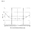
- FIG. 9 is a diagram showing the relation between the difference between thicknesses of base materials in the optical recording medium and jitter in the invention.
- FIGS. 10A and 10B are relation diagrams showing FS signal amplitude and a thickness difference of neighboring two layers, of the optical recording medium in the invention.
- FIG. 11 is a cross-sectional view of an example of an information recording face in which the thicknesses of two layers which are not neighboring are same in the invention.
- FIG. 12 is a cross-sectional view of an example of an optical recording medium 42 in the invention.
- FIG. 13 is a diagram showing the relation between actually measured jitter and layer-to-layer distance in the invention.
- FIG. 14 is a diagram showing the relation between the size of dust adhered to the surface of the optical recording medium and error length in the invention.
- FIG. 15 is a cross-sectional view of an optical recording medium in the invention.
- FIG. 16 is a diagram showing combinations of distances between layer surfaces having the possibility that reflection light of an information recording face to/from which information is recorded/reproduced is mixed with reflection light focused on the back side of another layer.
- FIG. 17 is a diagram showing an example of combinations of distances between layer surfaces in the invention.
- FIG. 18 is a diagram showing an example of combinations of distances between layer surfaces in the invention.
- FIG. 19 is a diagram showing the configuration of an optical recording medium and an optical pickup head constructing a conventional optical information apparatus.
- FIG. 20 is a diagram showing the configuration of another optical recording medium and an optical pickup head constructing a conventional optical information apparatus.
- FIGS. 1 and 2 A first embodiment of the invention will be described hereinbelow with reference to FIGS. 1 and 2 .
- FIG. 1 shows the configuration of an optical information apparatus according to the invention.
- An optical pickup head apparatus 201 (also called an optical pickup) emits a laser beam having a wavelength ⁇ of 405 nm to an optical recording medium 40 , and reproduces a signal recorded on the optical recording medium 40 .
- a transport controller 205 moves the optical pickup head apparatus 201 along the radial direction of the optical recording medium 40 in order to record/reproduce information in an arbitrary position on the optical recording medium 40 .
- a motor 206 for driving the optical recording medium 40 rotates the optical recording medium 40 .
- a controller 207 controls the optical pickup head apparatus 201 , the transport controller 205 , and the motor 206 .
- An amplifier 208 amplifies a signal read by the optical pickup head apparatus 201 .
- An output signal from the amplifier 208 is input to a controller 209 .
- the controller 209 On the basis of the output signal, the controller 209 generates servo signals such the FE signal and the TE signal necessary for the optical pickup head apparatus 201 to read the signal of the optical recording medium 40 and outputs the generated signals to the controller 207 .
- the signal input to the controller 209 is an analog signal, and the controller 209 converts the analog signal to a digital signal (binarization).
- a demodulator 210 analyzes the digital signal read from the optical recording medium 40 , reconstructs data of original video image, music, or the like, and outputs the reconstructed signal from an output unit 214 .
- a detector 211 detects an address signal or the like on the basis of the signal output from the controller 209 , and outputs the detected signal to a system controller 212 .
- the system controller 212 identifies the optical recording medium 40 on the basis of physical format information and optical recording medium manufacture information (optical recording medium management information) read from the optical recording medium 40 , decodes a recording/reproduction condition, and the like, and controls the whole optical information apparatus.
- the controller 207 controls the transport controller 205 in accordance with an instruction from the system controller 212 .
- the transport controller 205 moves the optical pickup head apparatus 201 onto a desired position on an information recording face 40 b formed on the optical recording medium 40 which will be described in FIG. 2 .
- the optical pickup head apparatus 201 records/reproduces information to/from the information recording face 40 b of the optical recording medium 40 .
- FIG. 2 shows an example of the configuration of the optical recording medium 40 and the optical pickup head apparatus 201 according to the invention.
- Four information recording faces are formed in the optical recording medium 40 .
- Information recording faces 40 a , 40 b , 40 c , and 40 d are formed in order from the side of the surface of the optical recording medium 40 .
- the base material thickness from the surface to the information recording face 40 a is d 1
- the base material thickness from the information recording face 40 a to the information recording face 40 b is d 2
- the base material thickness from the information recording face 40 b to the information recording face 40 c is d 3
- the base material thickness from the information recording face 40 c to the information recording face 40 d is d 4 .
- a light source 1 emits a linearly-polarized divergent beam 70 having a wavelength ⁇ of 405 nm.
- the beam 70 emitted from the light source 1 is transformed by a collimate lens 53 having a focal length f 1 of 18 mm to parallel rays.
- the parallel rays pass through a polarization beam splitter 52 and a quarter-wave plate 54 where the rays are transformed to circularly polarized light.
- the circularly polarized light is converted to a converged beam by an objective lens 56 having a focal length f 2 of 2 mm.
- the converged beam passes through a transparent substrate formed on the optical recording medium 40 and is condensed onto the information recording face 40 d .
- the opening of the objective lens 56 is regulated by an aperture 55 , and numerical aperture NA is 0.85.
- the collimate lens 53 is adjusted in the optical axis direction by using spherical aberration correcting units 93 constructed by a stepping motor or the like so that the spherical aberration becomes almost 0 m ⁇ in the information recording face 40 d .
- the beam 70 reflected by the information recording face 40 d passes through the objective lens 56 and the quarter-wave plate 54 and is transformed to a linearly polarized beam which is different from the incoming linearly polarized beam by 90 degrees, and is reflected by the polarization beam splitter 52 .
- the beam 70 reflected by the polarization beam splitter 52 is split by a diffraction grating (not shown) as a beam splitting device to a beam 70 of the 0 th order and beams of the first order (not shown).
- the beams pass through a condenser lens 59 whose focal length f 3 is 30 mm and a cylindrical lens 57 and enter a photodetector 32 .
- Astigmatism is given to the beam 70 incident on the photodetector 32 when the beam 70 passes through the cylindrical lens 57 .
- the beam 70 converged by the objective lens 56 forms an image on the information recording face 40 d
- a part of the beam 70 is reflected as a beam (not shown, hereinafter referred to as a beam 71 ) in accordance with the reflectance of the information recording face 40 c
- the beam 70 forms an image also on the information recording face 40 b .
- the light that forms an image on the information recording face 40 b is reflected according to the reflectance of the information recording face 40 b and is reflected again by the information recording face 40 c .
- the light travels in the same optical path as that of the light reflected from the information recording face 40 d to/from which information is to be inherently recorded/reproduced, and enters the photodetector 32 .
- the spot of the beam 70 and that of the beam 71 on the photodetector 32 have different light quantities and have shapes of almost the same size.
- the beam 70 includes an inherently necessary signal and, on the other hand, the beam 71 is an unnecessary signal component. Particularly, due to the interference between the beams 70 and 71 , a focus error signal fluctuates, and it becomes difficult to detect a stable signal depending on the light quantity of the beam 71 relative to the light quantity of the beam 70 .
- the focus fluctuation amount indicates the focus control position with respect to a focus error signal amplitude.
- the distance “d” between the information recording faces needs a certain degree of the minimum thickness to prevent the influence of crosstalk of neighboring information recording faces. Therefore, in the case of addressing the problem only by changing the base material thickness between neighboring information recording faces in the proposal of JP-A No. 2001-155380, the problem can be avoided only by increasing the base material thickness.
- the problem can be addressed only by the transmittance and the reflectance, so that the thickness between the information recording faces can be the minimum thickness. There is consequently an advantage such that the total distance from the surface of the optical recording medium to the deepest information recording face can be made short.
- FIG. 4 is a diagram showing an example of the configuration of an optical recording medium 41 according to a second embodiment.
- the transmittance th of the protection layer between the information recording faces of the optical recording medium and the reflectance ⁇ h of each of the information recording faces are set. In this case, however, flexibility of the transmittance th and the reflectance ⁇ h is regulated.
- flexibility in setting of the transmittance th and the reflectance ⁇ h can be increased.
- FIG. 5 shows the relation of a focus fluctuation amount to the thickness difference (d 4 ⁇ d 3 ) between the base material thickness d 4 and the base material thickness d 3 and Sb/Sd as the ratio of Sb as unnecessary light to Sd including an inherently necessary signal.
- the region of (d 4 ⁇ d 3 ) and Sb/Sd realizing the focus fluctuation amount of 10% or less at which the system is stable is shown by a hatched portion in FIG. 5 .
- the relation of the focus fluctuation amount with respect to the thickness difference and the light quantity ratio is also applied to the case of recording/reproducing information to/from another signal recording face.
- the number of the signal recording faces is not limited to four, and the relation is applied to an optical information recording medium comprising a plurality of signal recording faces.
- an optical recording medium having h signal recording faces by setting the transmittance th, reflectance ⁇ h, and the thickness dh ⁇ m so as to satisfy the relation of (( ⁇ (h ⁇ 1) 2 ⁇ (h ⁇ 2))/(th 2 ⁇ h)) ⁇ 0.0014 ⁇ (dh ⁇ d(h ⁇ 1)) 2 +0.0011 ⁇ (dh ⁇ d(h ⁇ 1))+0.0099, the focus fluctuation amount can be suppressed to 10% or less.
- the optical recording medium capable of obtaining a stable signal can be realized.
- the minimum thickness of the distance dh between signal recording faces By setting the minimum thickness of the distance dh between signal recording faces to 8 ⁇ m or larger, an optical recording medium which is not influenced by a crosstalk component of neighboring information recording faces in the system can be realized.
- the conditions under which the focus fluctuation amount becomes 10% or less are calculated by the thickness difference between the neighboring base materials (dh ⁇ d(h ⁇ 1)), concretely, (d 4 ⁇ d 3 ) and the light quantity ratio Sb/Sd of Sb as unnecessary light to Sd including an inherently necessary signal.
- the thickness difference between the neighboring base materials (dh ⁇ d(h ⁇ 1)), concretely, (d 4 ⁇ d 3 ) and the light quantity ratio Sb/Sd of Sb as unnecessary light to Sd including an inherently necessary signal.
- the thickness between the signal recording faces is d ⁇ m and the refractive index of the base material between the signal recording face “h” and the signal recording face “h ⁇ 1” is nh
- the transmittance th, reflectance ⁇ h, and the refractive index nh so as to satisfy the relation of (( ⁇ (h ⁇ 1) 2 ⁇ (h ⁇ 2))/(th 2 ⁇ h)) ⁇ 0.0006 ⁇ (d ⁇ (nh ⁇ n(h ⁇ 1))) 2 +0.0007 ⁇ (d ⁇ (nh ⁇ n(h ⁇ 1))+0.0099
- the focus fluctuation amount can be suppressed to 10% or less.
- FIG. 6 shows the relation of the focus fluctuation amount.
- a region of the focus fluctuation amount of 10% or less in which the system is stable is a hatched portion in FIG. 6 .
- the configuration in which the distance between the information recording faces is d ⁇ m which is almost constant has been described in the invention, similar effects can be obtained also by changing the refractive index nh of the base material between neighboring information recording faces in addition to the configuration in which the distance dh ⁇ m between neighboring information recording faces is changed in the second embodiment.
- FIG. 7 shows the relation of the focus fluctuation amount.
- a region of the focus fluctuation amount of 10% or less in which the system is stable is a hatched portion in FIG. 7 .
- a recordable optical recording medium can be provided.
- the optical recording medium can be identified easily.
- FIG. 8 is a diagram showing an example of the configuration of an optical recording medium 42 and the optical pickup head apparatus 201 according to a fourth embodiment.
- the optical recording medium 42 has n (n denotes an integer of 4 or larger) information recording faces.
- An information recording face 42 a closest to the surface 42 z of the optical recording medium 42 , an information recording face 42 d furthest from the surface 42 z , and an information recording face group 42 x disposed between the information recording faces 42 a and 42 d are formed.
- the interlayer distance from the surface 42 z to the information recording face 42 a is d( 1 )
- each of the interlayer distances between neighboring information recording faces up to the information recording face 42 d is d(n).
- a light source 1 emits a linearly-polarized divergent beam 70 having a wavelength ⁇ of 405 nm.
- the beam 70 emitted from the light source 1 is transformed by a collimate lens 53 having a focal length f 1 of 18 mm to parallel rays.
- the parallel rays pass through a polarization beam splitter 52 and a quarter-wave plate 54 where the rays are transformed to circularly polarized light.
- the circularly polarized light is converted to a converged beam by an objective lens 56 having a focal length f 2 of 2 mm.
- the converged beam passes through a transparent substrate formed on the optical recording medium 42 and is condensed onto the information recording face 42 d .
- the opening of the objective lens 56 is regulated by an aperture 55 , and numerical aperture NA is 0.85.
- the collimate lens 53 is adjusted in the optical axis direction by using spherical aberration correcting units 93 constructed by a stepping motor or the like so that the spherical aberration becomes the minimum on the information recording face 42 d.
- the beam 70 reflected by the information recording face 42 d passes through the objective lens 56 and the quarter-wave plate 54 and is transformed to a linearly polarized beam which is different from the incoming linearly polarized beam by 90 degrees, and is reflected by the polarization beam splitter 52 .
- the beam 70 reflected by the polarization beam splitter 52 passes thorough a condenser lens 59 whose focal length f 3 is 30 mm and a cylindrical lens 57 and enters a photodetector 32 . Astigmatism is given to the beam incident on the photodetector 32 when the beam passes through the cylindrical lens 57 .
- the photodetector 32 has not-shown four light receiving parts and outputs current signals according to received light amounts. From the current signals, a focus error (hereinbelow, called FE) signal according to the astigmation method, a tracking error (hereinbelow, called TE) signal according to the push-pull method, and an information (hereinbelow RF) signal recorded on the recording medium 42 are generated.
- the FE signal and the TE signal are subjected to amplification and phase-compensation to a desired level, and the resultant signals are supplied to actuators 91 and 92 and subjected to focus and tracking controls.
- the objective lens 56 is designed so that spherical aberration becomes zero in an intermediate position between the information recording faces 42 a and 42 d . Therefore, the largest spherical aberration occurs in the case where the beam is condensed to the information recording faces 42 a and 42 d as information recording faces which are the furthest from the position.
- the position of the collimate lens 53 is adjusted in the optical axis direction by the spherical aberration correcting units 93 in order to eliminate the spherical aberration, a third-order component as a major component in the spherical aberration can be eliminated and the spherical aberration can be largely reduced.
- components of higher-order mainly fifth-order components
- the size increases toward the information recording face 42 a or 42 d , and it worsens jitter.
- FIG. 9 is a diagram showing the relation between the base material thickness difference and jitter in the optical recording medium 42 according to the fourth embodiment.
- the axis of abscissa denotes the base material thickness difference as the difference between depth of an information recording face in which jitter is calculated and a reference position which is an intermediate position between the information recording faces 42 a and 42 d in the optical recording medium 42 , and the axis of ordinate indicates the jitter.
- the diagram shows a simulation result calculated in consideration of only the spherical aberration as a cause of deteriorating the jitter with parameters of NA of 0.85, wavelength of 405 nm, refractive index of 1.62, track pitch of 0.32 ⁇ m, and the shortest pitch length of 0.149 ⁇ m.
- the jitter is almost constant in the range of the base material thickness difference from about ⁇ 46 ⁇ m to about +48 ⁇ m, and the jitter deteriorates out of the range. Therefore, by setting the depth positions of all of the information recording faces within the range of ⁇ 45 ⁇ m of the base material layer difference including variations (that is, the total interlayer distance as the distance between the information recording faces 42 a and 42 d is 90 ⁇ m or less), stable recording/reproduction can be realized without deteriorating the jitter.
- the interlayer distances d( 1 ) to d(n) ⁇ m are set so as to satisfy the following equation when variations in the thickness of the interlayer distances are ⁇ e( 1 ) to ⁇ e(n) ⁇ m.
- the thickness of arbitrary two layers are set so as to have the thickness difference of at least 1 ⁇ m including a thickness variation amount of each layer.
- predetermined two layers do not have a thickness difference of at least 1 ⁇ m including a thickness variation amount, reflection light whose focus is achieved on the back side of another layer is mixed with reflection light of a recording layer to/from which information is recorded/reproduced, and recording/reproduction is disturbed.
- FIGS. 10A and 10B are diagrams showing the relation between the amplitude of an FS signal of a predetermined recording/reproduction layer and the thickness difference between neighboring two layers in the optical recording medium 42 in the fourth embodiment.
- the amplitude of an FS signal at the time of recording/reproducing information to/from the information recording face 42 d shown in the cross-sectional view of the optical recording medium 42 in FIG. 10A is actually measured while changing the thickness difference between d(n) and d(n ⁇ 1).
- FIG. 10B when the thickness difference between neighboring two layers becomes smaller than 1 ⁇ m, the amplitude of the FS signal largely increases. It is therefore understood that the minimum thickness difference of 1 ⁇ m or more is necessary (hereinbelow, 1 ⁇ m is described as the minimum value “emin” of the distance between layer surfaces).
- the increase in the FS signal amplitude is not limited to the case where two layers are adjacent to each other.
- FIG. 11 is a cross-sectional view of an information recording face as an example that two layers which are not adjacent to each other have the same thickness in the optical recording medium 41 .
- FIG. 12 is a cross-sectional view of an example of the optical recording medium 42 of the fourth embodiment.
- the minimum distance between layer surfaces (hereinbelow, “tmin”) of the distances d( 1 ) to d(n) ⁇ m each between layer surfaces of the fourth embodiment is set to 8 ⁇ m or larger.
- the distance between layer surfaces of a predetermined value or more is necessary. For example, when the beam 70 is condensed to the information recording face 42 d and the distance d(n) between layer surfaces is large, the spot diameter of the beam 70 on the neighboring information recording face is larger than that on the information recording face 42 d .
- the influence of a recording pit on the information recording face becomes relative small as compared with the spot diameter, and the influence on the recording/reproduction of information to/from the information recording face 42 d becomes smaller.
- equivalent parameters are calculated and a necessary minimum distance between layer surfaces is set.
- the spot diameter on the other layer is obtained by 40 ⁇ m/n ⁇ tan (arc sin(NA)) when the refractive index is “n”.
- the track pitch and the recording pit size can be reduced in proportion to the wavelength/NA as compared with a DVD.
- the spot diameter is allowed to be decreased in proportion to the wavelength/NA. From the parameters, the spot diameter on a neighboring information recording face in the embodiment is calculated and the distance between layer surfaces equivalent to the distance 40 ⁇ m between layer surfaces of the two-layer disk of a DVD is inversely calculated as 8 ⁇ m.
- FIG. 13 is a diagram showing the relation between actually measured jitter and the distance between layer surfaces.
- FIG. 14 is a diagram showing the relation between the size of a dust adhered to the surface of an optical recording medium and error length.
- d( 1 ) as the length from the surface to the information recording face is small, the influence on recording/reproduction increases.
- the error length is zero for a dust of about 45 ⁇ m or less.
- the error length is zero for a dust of about 27 ⁇ m or less.
- the error length is zero for a dust of about 20 ⁇ m or less.
- the ratio of dusts having a size of 20 ⁇ m or less is very high. It is said that dusts having a size of 25 ⁇ m or less occupy 80% of the total. Therefore, to prevent occurrence of an error with a dust having a size of 25 ⁇ m or less, the thickness d( 1 ) is set to 50 ⁇ m or larger.
- the total distance as the distance between the information recording faces 42 a and 42 d is set to 90 ⁇ m or less, so that occurrence of a jitter caused by the spherical aberration is suppressed and stable recording/reproduction can be realized.
- Two arbitrary layers of distances have the thickness difference of at least 1 ⁇ m including a thickness variation amount, and four continuous layers are set so that the total thickness of two layers and that of the other two layers have a thickness difference of at least 1 ⁇ m including the variation amount. Consequently, reflection light from the recording layer to/from which information is recorded/reproduced is not mixed with reflection light achieving focus on the back side of another layer, and stable recording/reproduction can be realized.
- the minimum distance between layer surfaces is set to 8 ⁇ m or larger, the influence from the neighboring information recording face is reduced, and recording/reproduction with little noise can be realized.
- the thickness of d( 1 ) is set to 50 ⁇ m or larger, so that very reliable recording/reproduction with the small number of recording/reproduction errors caused by dusts can be realized.
- the spherical aberration correction is performed by moving the collimate lens 53 in the optical axis direction by using the spherical aberration correcting units 93 in the embodiment, the invention is not limited to the embodiment. Similar effects can be obtained by a configuration capable of generating a three-dimensional spherical aberration or pseudo three-dimensional aberration of a size which can cancel out the spherical aberration occurring in the optical recording medium 42 .
- two lenses may be employed in place of the collimator lens 53 and the distance between the lenses is changed, thereby making the beam 70 converged or diverged.
- a liquid crystal panel in place of the collimate lens 53 and make the beam 70 converged or diverged by partially changing the phase of the beam 70 that passes.
- An example of the configuration of an optical recording medium 43 and an optical pickup head apparatus 201 in a fifth embodiment is similar to that of FIG. 2 .
- FIG. 15 is a cross-sectional view of the optical recording face 43 according to the fifth embodiment.
- a total average value of the distances d( 1 ) to d( 4 ) is 100 ⁇ m.
- a high-density optical disk called a BD which is developed in recent years uses a laser having the wavelength of 405 nm and an objective lens of NA 0.85, which is the same as this embodiment.
- the information recording faces exist at the depths of 75 ⁇ m (first layer) and 100 ⁇ m (the zeroth layer).
- the depth of the information recording face 43 d is made equal to the zero-th order of a BD.
- candidate values of the distances d( 1 ), d( 2 ), d( 3 ), and d( 4 ) are set as t 1 , t 2 , t 3 , and t 4 (t 1 ⁇ t 2 ⁇ t 3 ⁇ t 4 ), their distance variations are described as ⁇ f 1 , ⁇ f 2 , ⁇ f 3 , and ⁇ f 4 , respectively, and the minimum distance value 1 ⁇ m is described as emin, necessary conditions for t 1 , t 2 , t 3 , and t 4 can be expressed as follows.
- the distance variations ⁇ f 1 , ⁇ f 2 , and ⁇ f 3 have to be set within the range that t 1 +t 2 +t 3 is equal to or less than 90 ⁇ m.
- d( 1 ) has to be the maximum value t 4 among t 1 , t 2 , t 3 , and t 4 .
- FIG. 16 is a diagram showing an example of combinations of distances in which reflected light from an information recording face to/from which information is recorded/reproduced may be mixed with reflected light that comes into a focus on the back side of another layer in the embodiment.
- the combination 3 relates to the case where light is condensed on a recording/reproduction face 43 d to perform recording/reproduction, a part of the beam 70 is reflected by another information recording face 43 a , and is condensed on the back side of the surface 43 z .
- the distance from the surface 43 z to the information recording face 43 a is described as A, and the distance from the information recording face 43 a to the information recording face 43 d is written as B.
- the condition that reflected light from the information recording face 43 d is not mixed with reflected light from the back side of the surface 43 z is that the difference between the total sum of A and the total sum of B is larger than a value obtained by adding variations of the distances by 1 ⁇ m or more. This condition has to be satisfied with respect to all of the ten combinations shown in FIG. 16 .
- FIG. 17 is a diagram showing an example of combinations of the distances in the embodiment.
- the thickness d( 2 ) and that of d( 4 ) can be replaced with each other.
- the total sum of the distances d( 1 ) to d( 4 ) lies within the range of 100 ⁇ 12 ⁇ m, advantages similar to the above-described advantages can be obtained.
- a signal can be stably recorded.
- the combinations of the distances satisfying the above-described conditions are not limited to the example shown in FIG. 17 .
- the conditions can be satisfied by the combinations of the distances shown in FIG. 18 .
- the number of information recording faces is four.
- the invention is not limited to the number but the number may be, for example, three.
- an optical recording medium is constructed in such a manner that first to third information recording faces are provided from the side close to the surface, the distance from the surface to the first information recording face is d 1 ( ⁇ m), the distance from the first information recording face to the second information recording face is d 2 ( ⁇ m), and the distance from the second information recording face to the third information recording face is d 3 ( ⁇ ), and d 1 ⁇ 50 ( ⁇ m), d 2 +d 3 ⁇ 16 ( ⁇ m), d 2 +d 3 ⁇ 90 ( ⁇ m), and
- ⁇ 1 ( ⁇ m) are satisfied.
- the present invention is useful to realize a high-density and high-capacity optical recording medium and the like.
Abstract
Description
- 1 light source
- 32 photodetector
- 40, 41, 42, 43 optical recording media
- 40 a to 40 d, 41 a to 41 d, 42 a to 42 d, 43 a to 43 d information recording faces
- 52 polarization beam splitter
- 53 collimate lens
- 54 quarter-wave plate
- 55 aperture
- 56 objective lens
- 57 cylindrical lens
- 59 detection lens
- 70, 71 beams
- 91, 92 actuators
- 93 spherical aberration correcting units
Sd=t12 ×t22 ×t32 ×t42×α4
Sb=t12 ×t22 ×t32×α32×α2
|d(i)−d(k)|≧e(i)+e(k)+1 (where i and k are integers satisfying 1≦i≦n and 1≦k≦n and i≠k)
|d(j−3)+d(j−2)−d(j−1)−d(j)|≧e(j−3)+e(j−2)+e(j−1)+e(j)+1
d(1)=t4≧(t1+t2+t3)+(f1+f2+f3+f4)+emin
d(1)≧d(2)+d(3)+d(4)+e(1)+e(2)+e(3)+e(4)+emin
|d(2)+d(3)−d(4)|≧e(2)+e(3)+e(4)+emin and
|d(2)−d(3)−d(4)|≧e(2)+e(3)+e(4)+emin
|d(2)+d(3)−d(4)|=tmin+f1+f2+f3+emin≧e(2)+e(3)+e(4)+emin
|d(2)−d(3)−d(4)|=tmin+3f1+3f2+f3+3emin≧e(2)+e(3)+e(4)+emin
Claims (8)
Applications Claiming Priority (5)
| Application Number | Priority Date | Filing Date | Title |
|---|---|---|---|
| JP2004-229257 | 2004-08-05 | ||
| JP2004229257 | 2004-08-05 | ||
| JP2004255207 | 2004-09-02 | ||
| JP2004-255207 | 2004-09-02 | ||
| PCT/JP2005/014444 WO2006013978A1 (en) | 2004-08-05 | 2005-08-05 | Optical recording medium, optical recording medium information recording/reproducing method and information recording/reproducing device |
Publications (2)
| Publication Number | Publication Date |
|---|---|
| US20090028027A1 US20090028027A1 (en) | 2009-01-29 |
| US7778135B2 true US7778135B2 (en) | 2010-08-17 |
Family
ID=35787256
Family Applications (1)
| Application Number | Title | Priority Date | Filing Date |
|---|---|---|---|
| US11/659,034 Active 2027-07-16 US7778135B2 (en) | 2004-08-05 | 2005-08-05 | Optical recording medium, method for recording/reproducing information to/from optical recording medium and apparatus for recording/reproducing information |
Country Status (4)
| Country | Link |
|---|---|
| US (1) | US7778135B2 (en) |
| JP (1) | JP4965259B2 (en) |
| CN (1) | CN101015008B (en) |
| WO (1) | WO2006013978A1 (en) |
Cited By (2)
| Publication number | Priority date | Publication date | Assignee | Title |
|---|---|---|---|---|
| US20110205867A1 (en) * | 2010-02-22 | 2011-08-25 | Takashi Kikukawa | Optical recording medium, and series of optical recording media |
| US20210311291A1 (en) * | 2020-04-03 | 2021-10-07 | Panasonic Intellectual Property Management Co., Ltd. | Objective lens, optical head device, optical information apparatus, optical disk system, and method for inspecting objective lens |
Families Citing this family (8)
| Publication number | Priority date | Publication date | Assignee | Title |
|---|---|---|---|---|
| JP4994178B2 (en) * | 2006-10-10 | 2012-08-08 | パナソニック株式会社 | Optical recording medium, information recording or reproducing method, and information recording or reproducing apparatus |
| JP2008204517A (en) * | 2007-02-19 | 2008-09-04 | Hitachi Media Electoronics Co Ltd | Optical head and optical information recording and reproducing device |
| US20100118685A1 (en) * | 2008-11-12 | 2010-05-13 | Yoshiaki Komma | Optical recording medium, manufacturing method for optical recording medium, information recording/reproducing method and information recording/reproducing device |
| MX2010012805A (en) * | 2008-11-12 | 2010-12-07 | Panasonic Corp | Optical recording medium and optical information device. |
| US20110075534A1 (en) * | 2008-11-13 | 2011-03-31 | Yoshiaki Komma | Optical recording medium, and optical information device |
| WO2010070811A1 (en) * | 2008-12-17 | 2010-06-24 | パナソニック株式会社 | Optical disc recording medium, optical disc device, and integrated circuit used in optical disc device |
| JP2011192377A (en) * | 2010-02-22 | 2011-09-29 | Tdk Corp | Optical recording medium and optical recording-reading method |
| JP2011119026A (en) * | 2011-03-22 | 2011-06-16 | Panasonic Corp | Optical pickup device and objective lens used for the same |
Citations (8)
| Publication number | Priority date | Publication date | Assignee | Title |
|---|---|---|---|---|
| JPH03209642A (en) | 1990-01-11 | 1991-09-12 | Matsushita Electric Ind Co Ltd | Optical information medium, its production and its cassette case |
| JPH06267110A (en) | 1993-01-04 | 1994-09-22 | Philips Electron Nv | Multi-plane information storage system and recording medium using said system |
| US5864530A (en) | 1993-01-04 | 1999-01-26 | U.S. Philips Corporation | Multiplane information storage system and record carrier for use in such a system |
| US6187406B1 (en) * | 1997-03-17 | 2001-02-13 | Kabushiki Kaisha Toshiba | Optical disk and optical disk drive |
| JP2001155380A (en) | 2000-10-27 | 2001-06-08 | Victor Co Of Japan Ltd | Optical recording medium |
| JP3209642B2 (en) | 1994-07-11 | 2001-09-17 | 日本放送協会 | Waveguide splitter |
| US20040139459A1 (en) | 2002-12-27 | 2004-07-15 | Tdk Corporation | Optical recording medium |
| US6893698B2 (en) * | 2001-10-12 | 2005-05-17 | Matsushita Electric Industrial Co., Ltd. | Optical information recording medium, optical measuring method and optical information recording/reproducing method |
-
2005
- 2005-08-05 JP JP2006531601A patent/JP4965259B2/en active Active
- 2005-08-05 CN CN2005800260915A patent/CN101015008B/en active Active
- 2005-08-05 WO PCT/JP2005/014444 patent/WO2006013978A1/en active Application Filing
- 2005-08-05 US US11/659,034 patent/US7778135B2/en active Active
Patent Citations (13)
| Publication number | Priority date | Publication date | Assignee | Title |
|---|---|---|---|---|
| US5134604A (en) | 1990-01-11 | 1992-07-28 | Matsushita Electric Industrial Co., Ltd. | Combination optical data medium with multiple data surfaces and cassette therefor |
| JPH03209642A (en) | 1990-01-11 | 1991-09-12 | Matsushita Electric Ind Co Ltd | Optical information medium, its production and its cassette case |
| JPH06267110A (en) | 1993-01-04 | 1994-09-22 | Philips Electron Nv | Multi-plane information storage system and recording medium using said system |
| US5511057A (en) | 1993-01-04 | 1996-04-23 | U.S. Philips Corporation | Multiplane information storage system with an improved record carrier |
| US5864530A (en) | 1993-01-04 | 1999-01-26 | U.S. Philips Corporation | Multiplane information storage system and record carrier for use in such a system |
| JP3209642B2 (en) | 1994-07-11 | 2001-09-17 | 日本放送協会 | Waveguide splitter |
| US6606291B2 (en) * | 1997-03-17 | 2003-08-12 | Kabushiki Kaisha Toshiba | Optical disk and optical disk drive |
| US6187406B1 (en) * | 1997-03-17 | 2001-02-13 | Kabushiki Kaisha Toshiba | Optical disk and optical disk drive |
| JP2001155380A (en) | 2000-10-27 | 2001-06-08 | Victor Co Of Japan Ltd | Optical recording medium |
| US6893698B2 (en) * | 2001-10-12 | 2005-05-17 | Matsushita Electric Industrial Co., Ltd. | Optical information recording medium, optical measuring method and optical information recording/reproducing method |
| US20040139459A1 (en) | 2002-12-27 | 2004-07-15 | Tdk Corporation | Optical recording medium |
| JP2004213720A (en) | 2002-12-27 | 2004-07-29 | Tdk Corp | Optical recording medium |
| US7143426B2 (en) | 2002-12-27 | 2006-11-28 | Tdk Corporation | Multilayer optical recording medium with thickness ranges reducing interlayer cross-talk |
Non-Patent Citations (1)
| Title |
|---|
| Noriyoshi Shida et al., "The BD-Type Multi-Layer 100 GB ROM Disk using the Photopolymer Sheet", Technical Digest of International Symposium on Optical Memory, Nov. 3, 2003, pp. 10-11. |
Cited By (3)
| Publication number | Priority date | Publication date | Assignee | Title |
|---|---|---|---|---|
| US20110205867A1 (en) * | 2010-02-22 | 2011-08-25 | Takashi Kikukawa | Optical recording medium, and series of optical recording media |
| US8520481B2 (en) * | 2010-02-22 | 2013-08-27 | Tdk Corporation | Optical recording medium, and series of optical recording media |
| US20210311291A1 (en) * | 2020-04-03 | 2021-10-07 | Panasonic Intellectual Property Management Co., Ltd. | Objective lens, optical head device, optical information apparatus, optical disk system, and method for inspecting objective lens |
Also Published As
| Publication number | Publication date |
|---|---|
| JP4965259B2 (en) | 2012-07-04 |
| US20090028027A1 (en) | 2009-01-29 |
| WO2006013978A1 (en) | 2006-02-09 |
| CN101015008A (en) | 2007-08-08 |
| JPWO2006013978A1 (en) | 2008-05-01 |
| CN101015008B (en) | 2011-11-09 |
Similar Documents
| Publication | Publication Date | Title |
|---|---|---|
| US7778135B2 (en) | Optical recording medium, method for recording/reproducing information to/from optical recording medium and apparatus for recording/reproducing information | |
| US7542382B2 (en) | Optical pick-up head, optical information apparatus, and optical information reproducing method | |
| US7142484B2 (en) | Optical information processing system using optical aberrations and information medium having recording layer protected by transparent layer having thickness irregularity | |
| US7260032B2 (en) | Focal point adjusting method, and optical pickup device | |
| US6667947B2 (en) | Optical multi-layer information recordating medium | |
| US20070041287A1 (en) | Optical pickup apparatus capable of detecting and compensating for spherical aberration caused by thickness variation of recording layer | |
| JPWO2008149522A1 (en) | Optical head device and recording and / or reproducing device | |
| KR20120125043A (en) | Optical pickup and optical information storage medium system | |
| JP3919661B2 (en) | Manufacturing method of optical information recording medium | |
| US7298675B2 (en) | Multilayer recording medium and optical pickup for recording and/or reproducing the same | |
| JP4366813B2 (en) | Optical pickup device and coupling lens for optical pickup device | |
| US20080316891A1 (en) | Optical Scanning Device | |
| US6839189B2 (en) | Objective lens, optical pickup device, recorder and reproducer | |
| US8259554B2 (en) | Optical head device, optical information device, and diffractive element | |
| JP2004259439A (en) | Optical disk and its recording and playing-back device | |
| JP2005339751A (en) | Optical reproducing method, optical pickup device, optical reproducing device, and optical recording medium | |
| JP2005166257A (en) | Optical information recording medium | |
| JP4356017B2 (en) | OPTICAL HEAD DEVICE AND INFORMATION PROCESSING DEVICE USING OPTICAL RECORDING MEDIUM | |
| JP4501275B2 (en) | Optical head, light emitting / receiving element, optical recording medium recording / reproducing apparatus, and track discrimination signal detecting method | |
| JP2007080341A (en) | Optical pickup apparatus | |
| KR20000048173A (en) | Objective lens for correcting chromatic aberration for use in recording to or reproducing from optical information recording medium and optical pickup apparatus therewith | |
| JPH11328716A (en) | Optical head device and aberration compensating method for the device | |
| CN101140770A (en) | Optical pickup and optical disc apparatus |
Legal Events
| Date | Code | Title | Description |
|---|---|---|---|
| AS | Assignment |
Owner name: MATSUSHITA ELECTRIC INDUSTRIAL CO., LTD., JAPAN Free format text: ASSIGNMENT OF ASSIGNORS INTEREST;ASSIGNORS:ANZAI, JOJI;KADOWAKI, SHINICHI;KAJINO, OSAMU;AND OTHERS;REEL/FRAME:021102/0071 Effective date: 20070109 |
|
| AS | Assignment |
Owner name: PANASONIC CORPORATION, JAPAN Free format text: CHANGE OF NAME;ASSIGNOR:MATSUSHITA ELECTRIC INDUSTRIAL CO., LTD.;REEL/FRAME:021779/0851 Effective date: 20081001 Owner name: PANASONIC CORPORATION,JAPAN Free format text: CHANGE OF NAME;ASSIGNOR:MATSUSHITA ELECTRIC INDUSTRIAL CO., LTD.;REEL/FRAME:021779/0851 Effective date: 20081001 |
|
| STCF | Information on status: patent grant |
Free format text: PATENTED CASE |
|
| FEPP | Fee payment procedure |
Free format text: PAYOR NUMBER ASSIGNED (ORIGINAL EVENT CODE: ASPN); ENTITY STATUS OF PATENT OWNER: LARGE ENTITY |
|
| FPAY | Fee payment |
Year of fee payment: 4 |
|
| MAFP | Maintenance fee payment |
Free format text: PAYMENT OF MAINTENANCE FEE, 8TH YEAR, LARGE ENTITY (ORIGINAL EVENT CODE: M1552) Year of fee payment: 8 |
|
| MAFP | Maintenance fee payment |
Free format text: PAYMENT OF MAINTENANCE FEE, 12TH YEAR, LARGE ENTITY (ORIGINAL EVENT CODE: M1553); ENTITY STATUS OF PATENT OWNER: LARGE ENTITY Year of fee payment: 12 |