US7806824B2 - Ultrasound diagnosis apparatus - Google Patents
Ultrasound diagnosis apparatus Download PDFInfo
- Publication number
- US7806824B2 US7806824B2 US10/964,422 US96442204A US7806824B2 US 7806824 B2 US7806824 B2 US 7806824B2 US 96442204 A US96442204 A US 96442204A US 7806824 B2 US7806824 B2 US 7806824B2
- Authority
- US
- United States
- Prior art keywords
- probe
- coordinate data
- current
- coordinate
- recorded
- Prior art date
- Legal status (The legal status is an assumption and is not a legal conclusion. Google has not performed a legal analysis and makes no representation as to the accuracy of the status listed.)
- Expired - Fee Related, expires
Links
- 238000002604 ultrasonography Methods 0.000 title claims abstract description 104
- 238000003745 diagnosis Methods 0.000 title claims abstract description 73
- 239000000523 sample Substances 0.000 claims abstract description 223
- 238000005259 measurement Methods 0.000 claims description 14
- 238000000034 method Methods 0.000 description 37
- 230000000875 corresponding effect Effects 0.000 description 15
- 230000002596 correlated effect Effects 0.000 description 10
- 238000010586 diagram Methods 0.000 description 7
- 230000005540 biological transmission Effects 0.000 description 5
- 230000000052 comparative effect Effects 0.000 description 3
- 238000004364 calculation method Methods 0.000 description 2
- 201000010099 disease Diseases 0.000 description 2
- 208000037265 diseases, disorders, signs and symptoms Diseases 0.000 description 2
- 238000011156 evaluation Methods 0.000 description 2
- 230000003287 optical effect Effects 0.000 description 2
- 239000008280 blood Substances 0.000 description 1
- 210000004369 blood Anatomy 0.000 description 1
- 239000003086 colorant Substances 0.000 description 1
- 230000006835 compression Effects 0.000 description 1
- 238000007906 compression Methods 0.000 description 1
- 238000001514 detection method Methods 0.000 description 1
- 210000003238 esophagus Anatomy 0.000 description 1
- 230000035876 healing Effects 0.000 description 1
- 238000000691 measurement method Methods 0.000 description 1
- 238000011326 mechanical measurement Methods 0.000 description 1
- 238000009877 rendering Methods 0.000 description 1
- 239000011347 resin Substances 0.000 description 1
- 229920005989 resin Polymers 0.000 description 1
- 238000004088 simulation Methods 0.000 description 1
- 230000002194 synthesizing effect Effects 0.000 description 1
- 230000000007 visual effect Effects 0.000 description 1
Images


Classifications
-
- A—HUMAN NECESSITIES
- A61—MEDICAL OR VETERINARY SCIENCE; HYGIENE
- A61B—DIAGNOSIS; SURGERY; IDENTIFICATION
- A61B8/00—Diagnosis using ultrasonic, sonic or infrasonic waves
- A61B8/42—Details of probe positioning or probe attachment to the patient
- A61B8/4245—Details of probe positioning or probe attachment to the patient involving determining the position of the probe, e.g. with respect to an external reference frame or to the patient
- A61B8/4254—Details of probe positioning or probe attachment to the patient involving determining the position of the probe, e.g. with respect to an external reference frame or to the patient using sensors mounted on the probe
-
- A—HUMAN NECESSITIES
- A61—MEDICAL OR VETERINARY SCIENCE; HYGIENE
- A61B—DIAGNOSIS; SURGERY; IDENTIFICATION
- A61B8/00—Diagnosis using ultrasonic, sonic or infrasonic waves
-
- A—HUMAN NECESSITIES
- A61—MEDICAL OR VETERINARY SCIENCE; HYGIENE
- A61B—DIAGNOSIS; SURGERY; IDENTIFICATION
- A61B8/00—Diagnosis using ultrasonic, sonic or infrasonic waves
- A61B8/42—Details of probe positioning or probe attachment to the patient
-
- A—HUMAN NECESSITIES
- A61—MEDICAL OR VETERINARY SCIENCE; HYGIENE
- A61B—DIAGNOSIS; SURGERY; IDENTIFICATION
- A61B8/00—Diagnosis using ultrasonic, sonic or infrasonic waves
- A61B8/46—Ultrasonic, sonic or infrasonic diagnostic devices with special arrangements for interfacing with the operator or the patient
- A61B8/461—Displaying means of special interest
- A61B8/463—Displaying means of special interest characterised by displaying multiple images or images and diagnostic data on one display
-
- G—PHYSICS
- G01—MEASURING; TESTING
- G01S—RADIO DIRECTION-FINDING; RADIO NAVIGATION; DETERMINING DISTANCE OR VELOCITY BY USE OF RADIO WAVES; LOCATING OR PRESENCE-DETECTING BY USE OF THE REFLECTION OR RERADIATION OF RADIO WAVES; ANALOGOUS ARRANGEMENTS USING OTHER WAVES
- G01S7/00—Details of systems according to groups G01S13/00, G01S15/00, G01S17/00
- G01S7/52—Details of systems according to groups G01S13/00, G01S15/00, G01S17/00 of systems according to group G01S15/00
- G01S7/52017—Details of systems according to groups G01S13/00, G01S15/00, G01S17/00 of systems according to group G01S15/00 particularly adapted to short-range imaging
- G01S7/52023—Details of receivers
-
- G—PHYSICS
- G01—MEASURING; TESTING
- G01S—RADIO DIRECTION-FINDING; RADIO NAVIGATION; DETERMINING DISTANCE OR VELOCITY BY USE OF RADIO WAVES; LOCATING OR PRESENCE-DETECTING BY USE OF THE REFLECTION OR RERADIATION OF RADIO WAVES; ANALOGOUS ARRANGEMENTS USING OTHER WAVES
- G01S7/00—Details of systems according to groups G01S13/00, G01S15/00, G01S17/00
- G01S7/52—Details of systems according to groups G01S13/00, G01S15/00, G01S17/00 of systems according to group G01S15/00
- G01S7/52017—Details of systems according to groups G01S13/00, G01S15/00, G01S17/00 of systems according to group G01S15/00 particularly adapted to short-range imaging
- G01S7/52053—Display arrangements
- G01S7/52057—Cathode ray tube displays
- G01S7/52068—Stereoscopic displays; Three-dimensional displays; Pseudo 3D displays
-
- G—PHYSICS
- G01—MEASURING; TESTING
- G01S—RADIO DIRECTION-FINDING; RADIO NAVIGATION; DETERMINING DISTANCE OR VELOCITY BY USE OF RADIO WAVES; LOCATING OR PRESENCE-DETECTING BY USE OF THE REFLECTION OR RERADIATION OF RADIO WAVES; ANALOGOUS ARRANGEMENTS USING OTHER WAVES
- G01S7/00—Details of systems according to groups G01S13/00, G01S15/00, G01S17/00
- G01S7/52—Details of systems according to groups G01S13/00, G01S15/00, G01S17/00 of systems according to group G01S15/00
- G01S7/52017—Details of systems according to groups G01S13/00, G01S15/00, G01S17/00 of systems according to group G01S15/00 particularly adapted to short-range imaging
- G01S7/52053—Display arrangements
- G01S7/52057—Cathode ray tube displays
- G01S7/52073—Production of cursor lines, markers or indicia by electronic means
Definitions
- the present invention relates to an ultrasound diagnosis apparatus, and in particular to a technique for supporting a probe operation (position and/or orientation adjustment) by a user.
- An ultrasound diagnosis apparatus has a function to display, on a screen of a display device, “a body mark (body symbol)” and a “probe mark (probe symbol)” as reference images along with an ultrasound image (image of living tissue, or living body image).
- the body mark is typically a simple, two-dimensional figure schematically representing a partial shape within a living body.
- a user may operate the device to select a specific body mark corresponding to a body part to be diagnosed using ultrasound from among a plurality of body marks which are prepared in advance.
- the body mark is displayed near the living body image.
- a probe mark is displayed overlapping the body mark.
- the probe mark is typically a figure of a simple line or simple box. The user can freely set the position and direction of the probe mark on the body mark.
- the user operates the probe while comparatively observing both images so that the content of the current ultrasound image becomes closer to the past ultrasound image. In this manner, it is possible for the user to find an appropriate position and an appropriate orientation of the probe in the current ultrasound examination through a trial and error process.
- Japanese Patent Laid-Open Publication No. 2000-201926 discloses an apparatus in which a three-dimensional body mark and a three-dimensional probe mark are displayed. In this apparatus, when a user changes a position of a probe mark, display content of a body mark is automatically changed so that the position of the probe mark is at a center position of the body mark.
- Japanese Patent Laid-Open Publication No. 2001-017433 also discloses an apparatus in which a three-dimensional body mark and a three-dimensional probe mark are displayed. In this apparatus, a body mark and a probe mark seen from a viewing direction designated by the user using an input unit are generated. A probe mark is displayed on an appropriate position on a body mark based on an actual positional relationship between a living body and the probe. In this case, the actual positional relationship is measured using a magnetic sensor (refer to paragraph 0025 of Japanese Patent Laid-Open Publication No. 2001-017433).
- the present invention advantageously provides an ultrasound diagnosis apparatus in which probe operation is supported to reduce load of the user.
- the present invention advantageously provides an ultrasound diagnosis apparatus in which the current diagnosis part can be quickly and easily matched or approximated to the past diagnosis part.
- the present invention advantageously provides an ultrasound diagnosis apparatus in which a disease can be properly evaluated or diagnosed based on a comparative observation between a past ultrasound image and a current ultrasound image.
- an ultrasound diagnosis apparatus comprising a probe which transmits and receives ultrasound and outputs received data, a coordinate measuring unit which measures at least one of a spatial position and orientation of the probe and outputs coordinate data representing a result of measurement, a coordinate storage unit which records recorded coordinate data, an information generator unit which generates probe operation support information based on the recorded coordinate data recorded in the coordinate storage unit and current coordinate data which is coordinate data currently output from the coordinate measuring unit, and an information provision unit which provides the probe operation support information to a user.
- recorded coordinate data is stored in advance through an instruction by a user or in an automatic manner.
- Probe operation support information is generated based on the recorded coordinate data and the current coordinate data which is currently obtained.
- the probe operation support information is provided to a user using a display device, a speaker, etc.
- a probe is, for example, a probe for measuring two-dimensional data or a probe for measuring three-dimensional data.
- a magnetic field measurement system as will be described below.
- the magnetic field measurement system preferably has a magnetic field generator provided on one of the probe and a predetermined fixed location, a magnetic sensor provided on the other one of the probe and the predetermined fixed location, and a coordinate data calculator which calculates the coordinate data based on an output of the magnetic sensor.
- a magnetic sensor of a relatively small size is provided within the probe and a magnetic field generator of a relatively large size is provided on a fixed location near a bed.
- the probe operation support information maybe information for supporting only one of the position adjustment operation and the orientation adjustment operation of the probe, but is preferably information for supporting both the position adjustment operation and the orientation adjustment operation of the probe.
- the probe operation support information can be provided through an image display, an acoustic output, an optical output, or one or a plurality of other means.
- the probe operation support information may be information spatially representing the recorded probe coordinate and the current probe coordinate or be information representing a relationship among the recorded probe coordinate and the current probe coordinate (such as, for example, difference and proximity direction).
- the information generator unit generates the probe operation support information by comparing the recorded coordinate data and the current coordinate data.
- the probe operation support information contains a guidance display and the guidance display indicates at least one of match or proximity between the recorded coordinate data and the current coordinate data.
- the guidance display contains an indicator array indicating, for each coordinate component, a match and a proximity between the recorded coordinate data and the current coordinate data.
- the indicator array further indicates, for each coordinate component, a polarity of a direction of proximity.
- the probe operation support information contains a reference image
- the reference image is an image which represents the recorded coordinate data and the current coordinate data in a three-dimensional coordinate system based on a subject.
- the reference image contains a recorded probe mark which is generated based on the recorded coordinate data and a current probe mark which is generated based on the current coordinate data.
- each of the recorded probe mark, the current probe mark, and the body mark is a three-dimensional image.
- an ultrasound diagnosis apparatus comprising a transportable probe which is operated by a user and which transmits and receives ultrasound and outputs received data, a coordinate measuring unit which measures a spatial position and orientation of the probe and outputs coordinate data representing a result of measurement, an instruction generator unit which generates a recording instruction, a coordinate storage unit which records recorded coordinate data at a timing in which the recording instruction is generated, an information generator unit which generates probe operation support information for approximating or matching, based on a comparison between the recorded coordinate data recorded in the coordinate storage unit and current coordinate data which is coordinate data currently output from the coordinate measuring unit, the current coordinate data to the recorded coordinate data, and an information provision unit which provides the probe operation support information to the user.
- the ultra sound diagnosis apparatus further comprises a display device which displays a current ultrasound image and the probe operation support information.
- the ultrasound diagnosis apparatus further comprises a display device which displays a current ultrasound image, a past ultrasound image, and the probe operation support information.
- the probe operation support information contains a reference image, the reference image contains a first graphical object generated based on the recorded coordinate data and a second graphical object generated based on the current coordinate data, and the second graphical object moves corresponding to a movement of the probe.
- the probe operation support information contains a guidance display, and the guidance display indicates a relationship between the recorded coordinate data and the current coordinate data for each coordinate component.
- a method is preferably used in which a center position on the transmission/reception surface of the probe is sequentially contacted with a plurality of parts on the subject for calibration which are set in advance and the size of the subject is measured (alternatively, it is also possible to use a method as described in Japanese Patent Application No. 2002-218497 which is not made public at the time of filing of a Japanese patent application for the present invention).
- FIG. 1 is a block diagram showing an overall structure of an ultrasound diagnosis apparatus according to a preferred embodiment of the present invention
- FIG. 2 is a diagram showing an example of a specific structure of a coordinate data table shown in FIG. 1 ;
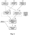
- FIG. 3 is a conceptual diagram for explaining a generation process of a reference image
- FIG. 4 is a diagram for explaining a coordinate system defined through calibration
- FIG. 5 is a diagram for explaining a reference image, a living body image, and a guidance display.
- FIG. 6 is a flowchart showing an operation of the apparatus shown in FIG. 1 .
- FIG. 1 is a block diagram showing an overall structure of an ultrasound diagnosis apparatus according to a preferred embodiment of the present invention.
- the ultrasound diagnosis apparatus has a function to display a reference image, a function to display a guidance display, etc. for supporting operations of the probe by the user.
- a probe 10 is a transportable device for transmitting and receiving ultrasound.
- the probe 10 has a transducer array including a plurality of transducer elements in the structure exemplified in FIG. 1 .
- the transducer array generates an ultrasound beam B.
- a two-dimensional scanning plane S is generated.
- As a method of electronic scanning it is possible to employ, for example, an electronic sector scanning system or an electronic linear scanning system. It is also possible to provide a 2D (two-dimensional) transducer array in the probe 10 to form a 3D (three-dimensional) data obtaining space.
- An ultrasound diagnosis apparatus comprises, as means for measuring coordinates, a magnetic field generator 14 , a magnetic sensor 12 , and a coordinate calculator unit 16 .
- the magnetic field generator 14 is provided at a predetermined fixed location, such as a position near a bed (not shown) on which a patient is located.
- the magnetic sensor 12 is provided on the probe 10 in the example configuration of FIG. 1 . More specifically, the magnetic sensor 12 is stored and located within a resin case in the probe 10 .
- Various devices may be used as the magnetic field generator 14 and the magnetic sensor 12 , as long as these devices can measure a three-dimensional position and a three-dimensional orientation of the probe 10 .
- the magnetic field generator 14 has, for example, three magnetic field generator coils provided corresponding to three axes which are perpendicular to each other. These three coils are driven in a time divisional manner.
- the magnetic sensor 12 comprises, for example, three magnetic filed detector coils provided corresponding to three axes which are perpendicular to each other.
- the coordinate calculator unit 16 calculates a spatial position (x, y, z) of the probe 10 and a rotational angle ( ⁇ , ⁇ , ⁇ ) of the probe 10 with respect to the axes based on output signals of the coils output from the magnetic sensor 14 .
- the coordinate measurement technique itself is a known technique. The definition of the components of the coordinate system may be other than those described above.
- the probe 10 is connected to a main system of the apparatus through a cable 18 . That is, the probe 10 in the embodiment is transportable and is, in general, used in contact with a surface of the body of the subject. Alternatively, it is also possible to use a probe 10 which is inserted into a body orifice, such the esophagus.
- a transmitter unit 20 functions as a transmission beam former.
- the transmitter unit 20 supplies, to the plurality of transducer elements, a plurality of transmission signals to which a delay process is applied, under the control of a controller unit 38 .
- a receiver unit 22 functions as a reception beam former.
- the receiver 22 applies a phase adjusting and summing process to a plurality of reception signals output from the plurality of transducer elements under a control of the controller unit 38 .
- a signal processor unit 24 applies processes such as detection and logarithmic compression to the phase adjusted and summed reception signal output from the receiver unit 22 . These processes may alternatively be applied downstream of a storage unit 26 which will be described below. In this configuration, an RF signal is stored in the storage unit 26 .
- the storage unit 26 stores reception signal (received data) before coordinates are converted. Alternatively, it is also possible to store, in the storage unit 26 , received data after coordinates are converted.
- the storage unit 26 has a cine-memory 28 and a coordinate data table 30 .
- the cine-memory 28 stores received data of a plurality of frames which are input in time series.
- the cine-memory 28 has a storage structure similar to a ring buffer.
- the cine-memory 28 always stores a sequence of received data from a most recent frame to a frame of a predetermined time before. As is known, when a user applies a freeze operation, transmission and reception of the ultrasound is terminated. At this point, the stored content in the cine-memory 28 is frozen.
- the coordinate data table 30 is a table which stores a plurality of coordinate data correlated to a plurality of received data stored in the cine-memory 28 .
- coordinate data correlated to the received data is stored in the coordinate data table 30 .
- the coordinate data represents a position and an orientation of the probe 10 at the time when the received data is obtained.
- one item of coordinate data is correlated to and stored with one item of received data. Therefore, similar to the cine-memory 28 , the coordinate data table 30 also has a storage structure similar to a ring buffer.
- the management unit of the received data in the cine-memory 28 may be, for example, beams, frames, or volumes.
- the management unit of coordinate data in the coordinate data table 30 may also be a unit such as beams, frames, or volumes, similar to the management unit of the received data.
- the correlation between the received data and the coordinate data is managed with one frame composed of a plurality of beams as the management unit, Alternatively, in this configuration, one coordinate data may be correlated to a plurality of received data. Alternatively, a plurality of coordinate data may be correlated to one received data.
- the coordinate data is formed as a set of parameter values of x, y, z, ⁇ , ⁇ , and ⁇ , as already described above.
- the present embodiment has an advantage that the body mark and the probe mark can be automatically generated and displayed using the coordinate data. Control to write data and control to read data to and from the storage unit 26 are executed by the controller unit 38 which will be described later. It is also possible to store an electrocardiographic signal in the cine-memory 28 along with the received data.
- coordinate data of past diagnoses is separately stored as recorded coordinate data, and probe operation support information, described later, is generated using the recorded coordinate data.
- the image generator unit 32 is means for generating an ultrasound image as a living body image based on the received data and has, for example, a digital scan converter (DSC).
- DSC digital scan converter
- a two-dimensional ultrasound image image of tissue and image of blood stream, etc.
- a three-dimensional image may be generated or an M mode image or a Doppler waveform image may be generated.
- a display processor unit 34 synthesizes image data as living body image output from the image generator unit 32 and graphical data output from a graphics generator unit 42 which will be described below and outputs data which represents a synthesized image.
- the image data output from the display processor unit 34 is sent to a display unit 36 .
- a synthesized image including the living body image and the graphical image is displayed on a screen of a display unit 36 .
- the graphical image contains a reference image.
- the reference image contains a body mark and one or a plurality of probe marks.
- the recorded probe mark is a graphical object generated based on the recorded coordinate data (graphical object re-creating a past position and a past orientation of the probe during past examination).
- the current probe mark is a graphical object generated based on the current coordinate data (graphical object representing a current position and a current orientation of the probe).
- the probe operation support information By simultaneously displaying the recorded probe mark and the current probe mark, it is possible to quickly and easily match the current position and the current orientation of the probe to the position and the orientation of the probe during the past examination.
- a past ultrasound image and a current ultrasound image are to be display side by side using a two-screen display function, such a reference image is used as the probe operation support information.
- a guidance display which will be described later is also used as the probe operation support information.
- the display unit 36 may alternatively be formed with two display devices (main display device and auxiliary display device).
- the living body image may be displayed on one of the two display devices and the graphical image may be displayed on the other of the two display devices.
- the synthesized image can be recorded on a recording medium such as a VTR and CD-ROM, printed on paper, or captured as a photograph. Because the synthesized image contains the reference image, it is possible to record the reference image along with the living body image.
- the controller unit 38 has a CPU for executing software instructions.
- the controller unit 38 controls operations of the structures shown in FIG. 1 and, in particular, supplies a graphics generation condition to the graphics generator unit 42 which is substantially formed by a software.
- the controller unit 38 has a calibration function, here embodied within a calibration execution unit 40 .
- a calibration process is executed before measurement in order to correlate (conform) a scale or a size in the body mark to a real scale or a real size in the subject by identifying a coordinate system in the subject.
- a center position of a transmission/reception surface of the probe 10 is contacted to a plurality of specific positions for calibration defined on the subject and coordinate data of the probe is obtained at each of the specific positions.
- a coordinate system in the subject is then identified based on the plurality of coordinate data corresponding to the plurality of specific positions. According to this identification, it is possible to conform the coordinate system with respect to the body mark to the coordinate system with respect to the subject.
- the conforming of coordinate systems includes matching of origins, matching of the scales or sizes, etc.
- a result of the calibration is supplied from the controller unit 38 to the coordinate calculator unit 16 .
- the coordinate calculator unit 16 calculates the probe coordinates based on an output signal of the magnetic sensor 12 and according to a coordinate system based on the subject defined through the calibration.
- the coordinate calculator unit 16 outputs the coordinate data which is the result of the calculation, to the coordinate data table 30 of the storage unit 26 and also to the controller unit 38 .
- the controller unit 38 receives the coordinate data output from the coordinate calculator unit 16 when the ultrasound image is to be displayed in real time.
- the controller unit 38 receives coordinate data read from the coordinate data table 30 .
- the controller unit 38 controls generation of the body mark and generation of the probe mark based on the received coordinate data, as will be described below.
- the three-dimensional body mark and the three-dimensional probe mark can be automatically displayed both in a configuration in which the ultrasound image is to be displayed in real time (real time display mode) and in a configuration in which the ultrasound image is to be replayed and displayed using received data which is stored in the cine-memory functioning as a storage device (replay display mode).
- the controller unit 38 comprises an evaluator unit 41 .
- the evaluator unit 41 evaluates proximity, proximity direction, and match, by comparing the recorded coordinate data and the current coordinate data.
- the controller unit 38 reads coordinate data output from the coordinate calculator unit 16 at a timing in which an explicit instruction is given by the user or at a timing when a predetermined condition is satisfied and stores the read coordinate data to an external storage device 50 as recorded coordinate data 50 A.
- the controller unit 38 stores, during the period when an ultrasound image is replayed and a specific ultrasound image is selected and stored for examination report, coordinate data corresponding to the specific ultrasound image to the external storage device 50 as the recorded coordinate data 50 A. With this configuration, coordinate data read from the coordinate data table 30 is utilized.
- the recorded coordinate data 50 A represents a position and an orientation of the probe during the past examination.
- the evaluator unit 41 compares the stored recorded coordinate data and the current coordinate data which is currently obtained in real time and outputs a result of comparison to a guidance display generator unit 47 provided in the graphics generator unit 42 .
- the evaluator unit 41 uses a speaker 49 to notify, with a predetermined sound, the user of information such as proximity and matching, based on the result of comparison. This configuration is one form of provision of the probe operation support information.
- the graphics generator unit 42 comprises a body mark generator unit 44 , a probe mark generator unit 46 , and a guidance display generator unit 47 .
- These generator units 44 and 46 are substantially realized by software in the present embodiment.
- a mark corresponding to the condition output by the controller unit 38 is selected from among a plurality of marks which are provided in advance or a mark is generated based on the condition output by the controller unit 38 when the controller unit 38 outputs the condition.
- the body mark generator unit 44 generates a monochrome or color three-dimensional body mark and the probe mark generator unit 46 generates a monochrome or color three-dimensional probe mark (recorded probe mark and current probe mark).
- the body mark and the probe mark may alternatively be digital images captured by a digital camera.
- the guidance display generator unit 47 generates a guidance display reflecting a result of evaluation in the evaluator unit 41 .
- the guidance display contains a plurality of indicators corresponding to a plurality of coordinate components forming the coordinate data. More specifically, the plurality of indicators correspond to all or a portion of coordinate components of x, y, z, ⁇ , ⁇ , and ⁇ .
- each indicator executes a display operation for identifying three forms of proximity in a positive direction, matching, and proximity in a negative direction. This display operation will be described later referring to FIG. 5 , etc. Alternatively, it is also possible to employ a configuration in which each indicator only displays matching.
- the graphics generator unit 42 functions both in the real time display mode and replay display mode. In other words, in both display modes, the body mark and the probe mark can be automatically generated according to a display condition output from the controller unit 38 . Graphical data containing these marks is supplied to the display processor unit 34 .
- the display processor unit 34 executes a process to synthesize the living body image data and the graphical data and supplies the data of the synthesized image generated in this process to the display unit 36 .
- the body mark generator unit 44 can generate a plurality of types of body marks. More specifically, the body mark generator unit 44 can generate a three-dimensional body mark having a suitable form corresponding to the diagnosis item, diagnosis part, type of patient, and size of patient. Information indicating the type of body mark is stored in the coordinate data table 30 as will be described below.
- the probe mark generator unit 46 can generate a plurality of types of probe marks. More specifically, the probe mark generator unit 46 can generate a three-dimensional probe mark having a shape corresponding to the type of probe. Information indicating the type of the probe mark is stored in the coordinate data table 30 as will be described later. It is also possible to allow the direction for displaying the body mark (direction of view line) to be variable.
- the position and orientation of the probe mark is adaptively set based on the actual position and orientation of the probe.
- the probe mark is displayed overlapping the body mark. In this manner, the actual usage state of the probe is simulated and re-created on the display screen.
- a known three-dimensional image constructing method such as, for example, volume rendering and surfacing method.
- An external storage device 50 is connected to the controller unit 38 and stores various data necessary for control of operations by the controller unit 38 .
- an operation panel 48 is connected to the controller unit 38 . A user can set and input various parameters using the operation panel 48 .
- the external storage device 50 stores one or a plurality of sets of recorded coordinate data.
- the plurality of sets of recorded coordinate data are managed, for example, for each subject and for each diagnosis part and one set of recorded coordinate data is selected by specifying a subject and a diagnosis part. It is also possible to employ a configuration in which one of the coordinate data stored in the coordinate data table 30 is used as the recorded coordinate data.
- the user can input a recording instruction of coordinate data using the operation panel 48 .
- the user can input an instruction for storing one of the ultrasound images (or received data for generating the ultrasound image) as an ultrasound image for examination report.
- the coordinate data correlated to the ultrasound image to be stored is automatically stored as the recorded coordinate data.
- the recorded coordinate data correlated to the ultrasound image is identified and user operation support information is generated based on the recorded coordinate data. For this purpose, a correlation relationship between the ultrasound image to be stored and the recorded coordinate data is managed.
- the ultrasound image can be stored in the storage unit 26 , the external storage device 50 , or any other storage medium.
- FIG. 2 shows a specific example structure of the coordinate data table 30 shown in FIG. 1 .
- the received data is managed in units of frames.
- Specific coordinate data 30 A is correlated to the frame number.
- the coordinate data is made of data x, y, and z representing the spatial position of the probe and data ⁇ , ⁇ , and ⁇ presenting the orientation of the probe.
- This configuration is only exemplary, and coordinate data of various forms may be used as long as the coordinate data allows appropriate display of the marks.
- the coordinate data table 30 stores body mark type information 30 B and probe mark type information 30 C in addition to the coordinate data.
- the type of the body mark is automatically selected based on medical information and patient information or is selected by the user.
- the type of the probe mark is automatically identified or is registered by the user. Because the information 30 B and 30 C are stored in the coordinate data table, the types of marks can be automatically selected using the information 30 B and 30 C both in the real time display mode and in the replay display mode.
- FIG. 3 is a conceptual diagram showing a process for generating a reference image.
- This example process shows a procedure for generating a reference image for matching a position and an orientation of a probe in current examination (that is, current diagnosis part) to a position and an orientation of a probe in a past examination (that is, past diagnosis part).
- a reference image is generated basically through the process shown in FIG. 3 .
- Step S 10 indicates a calibration step in the past examination and in the current examination. Either prior to or following the calibration, in step S 12 , a body mark type is designated and, in step S 14 , a probe mark type is designated. The mark types are designated automatically or by the user. In this configuration, it is preferable that a control is applied such that the body mark type and the probe mark type designated in the past examination are automatically selected in the current examination. In step S 16 , a body mark is generated and, in step S 18 , a recorded probe mark and a current probe mark are generated. In this process, the recorded probe mark is generated based on the recorded coordinate data as described above.
- the recorded probe mark is generated such that the recorded probe mark is synthesized on the body mark at a position indicated by the recorded coordinate data and with an orientation indicated by the recorded coordinate data.
- the current probe mark is generated in real time based on the coordinate data currently obtained in real time. More specifically, the current probe mark is generated such that the current probe mark is synthesized on the same body mark at a position indicated by the current coordinate data and with an orientation indicated by the current coordinate data.
- the recorded probe mark maybe a simulation of the actual form of the probe, or, alternatively, may be represented by a mark or a symbol such as an arrow indicating the position of contact and direction of contact of the probe.
- the recorded probe mark and current probe mark are generated according to a probe mark type designated in step S 14 .
- results of execution of the calibration in the past examination and in the current examination are considered.
- the body mark is generated based on the body mark type designated in step S 12 .
- results of execution of the calibration in the past examination and in the current examination are considered and the recorded coordinate data and the current coordinate data are considered as necessary.
- a specific body mark is selected from among a plurality of body marks belonging to the designated body mark type, according to the current coordinate data.
- a graphical image is generated by synthesizing the body mark (graphical data) and the recorded probe mark and the current probe mark (graphical data). More specifically, the reference image is generated according to the display condition. For example, a color coding process of skin color may be applied to the body mark and a color coding process reflecting the actual colors of the probe may be applied to the recorded probe mark and the current probe mark.
- a graphical image (that is, a reference image) is displayed on the screen along with the living body image according to the display condition which is set by the controller unit.
- the above-described processes are executed for each frame. For example, when the received data from the cine-memory is to be displayed as an animation image, the movement of the probe when the received data is obtained is re-created as the movement of the probe mark.
- FIG. 4 shows a coordinate system 60 defined regarding the body mark (or the subject).
- the coordinate system 60 is defined in the calibration process described above.
- FIG. 4 shows a typical body mark 62 .
- the coordinate system 60 has three perpendicular axes X, Y, and Z which pass though a coordinate origin O.
- the position and orientation of the probe in such coordinate system 60 is measured in real time by the above-described coordinate measuring means. It is also possible to three-dimensionally display, on the screen, the coordinate system as shown in FIG. 4 to achieve a representation to allow comparison between the position and orientation of the probe (or diagnosis part) during past examination and the current position and the current orientation of the probe (or diagnosis part).
- FIG. 5 shows an example of a display screen 64 .
- a living body image 66 and a reference image 68 are shown on the display screen 64 .
- the reference image 68 includes a body mark 70 , a recorded probe mark 73 , and a current probe mark 72 . These marks are three-dimensional images having a perceived depth.
- the recorded probe mark 73 re-creates the position and the orientation of the probe in the past diagnosis and is displayed on the body mark 70 at a position based on the recorded coordinate data and with an orientation based on the recorded coordinate data.
- the recorded probe mark 73 is represented as a halftone image such that the recorded probe mark 73 is visually distinguishable from the current probe mark which is displayed with a normal brightness.
- the current probe mark 72 represents the current position and the current orientation of the probe and is displayed on the body mark 70 at a position based on the current coordinate data and with an orientation based on the current coordinate data.
- the position or the orientation of the current probe mark is changed corresponding to the movement of he probe.
- the user can change the contact position and contact orientation of the probe to match the current probe mark 72 to the recorded probe mark 73 to easily approximate or match the diagnosis part in the current diagnosis to the diagnosis part in the past diagnosis.
- the past ultrasound image (still image) and the current ultrasound image (real time image) are simultaneously displayed using a two-screen display function also, it is desirable to display the reference image 68 .
- a display position of the reference image 68 on the display screen 64 can be arbitrarily set by the user. It is desirable to allow the user to arbitrarily set the size of the reference image. Alternatively, it is also possible to prepare a plurality of body marks representing the same part and having different directions and to automatically select the body mark to be displayed according to the position of the probe. It is also possible to allow generation of a plurality of body marks which can represents the state of a patient lying on a bed.
- the reference image as described above is one form of probe operation support information.
- other probe operation support information may be provided.
- a guidance display 74 shown on FIG. 5 has an indicator array having three indicators 76 corresponding to three coordinate components.
- the indicator array has three indicators 76 corresponding to the three coordinate components of X, Y, and Z.
- Each indicator 76 has a pair of triangular elements 80 and 82 which oppose each other in orientations opposite to each other and a circular element 78 provided between the triangular elements 80 and 82 .
- the triangular element corresponding to the closing direction is displayed with a higher brightness. With this configuration, it is possible to recognize that the probe is close in the X direction and the closing or proximate direction.
- the indicator array shown in FIG. 5 is for evaluating the current probe position.
- An additional indicator array may be provided for evaluating the current probe orientation.
- the user can be notified of the direction and an amount of movement the probe should be moved in real time. With either configuration, it is possible to quickly and easily match the current diagnosis part to the past diagnosis part and there is an advantage that the matched state can be visually and easily confirmed.
- the illustrated guidance display of FIG. 5 is only exemplary and other display forms may be employed. In the present embodiment, when matching is achieved for all coordinate components, a predetermined sound is output and recording, etc. of the ultrasound image is performed manually or automatically when the sound is output.
- FIG. 6 shows a flowchart of an operation to provide probe operation support information.
- steps S 30 and S 32 a recorded probe mark and a current probe mark are displayed. These steps are normally executed simultaneously, but are shown in FIG. 6 as separate steps for purposes of explaining the operation.
- step S 34 recorded coordinate data and current coordinate data are compared and a difference value is calculated for each coordinate component.
- step S 36 a guidance display is generated based on these difference values or the content of the guidance display which is already displayed is updated. When an exact match is determined between the past diagnosis part and the current diagnosis part in step S 38 , a predetermined sound is output in step S 40 .
- step S 42 When, on the other hand, an exact is not determined, the process jumps from step S 42 back to step S 32 and the steps described above are repeated. That is, the display position and display orientation of the current probe mark are changed in real time according to coordinate data measured in real time (step S 32 ) and the display content (form of display of the indicator for each coordinate component) of the guidance display is updated according to a result of difference calculation which is calculated in real time.
- the user can easily match the current probe position and orientation to the recorded probe position and orientation by observing the reference image and the guidance display.
- a sound is output in step S 40 when an exact match is achieved, and the image recording process is automatically or manually executed at that point.
- the sequence of steps from the step S 30 is executed in a manner similar to that described above.
- the probe operation support information generated based on the recorded coordinate data and the current coordinate data is not limited to that described above. It is also possible, for example, to configure to allow a plurality of types of probe operation support information to be generated and allow the user to select one or a plurality of information from among these information.
- probe operations by a user are supported and a load of the user can be reduced.
- An appropriate evaluation and an appropriate diagnosis can be provided based on a comparative observation of the past ultrasound image and the current ultrasound image.
Abstract
Description
Claims (10)
Applications Claiming Priority (2)
| Application Number | Priority Date | Filing Date | Title |
|---|---|---|---|
| JP2003361932A JP4263579B2 (en) | 2003-10-22 | 2003-10-22 | Ultrasonic diagnostic equipment |
| JP2003-361932 | 2003-10-22 |
Publications (2)
| Publication Number | Publication Date |
|---|---|
| US20050119569A1 US20050119569A1 (en) | 2005-06-02 |
| US7806824B2 true US7806824B2 (en) | 2010-10-05 |
Family
ID=34386503
Family Applications (1)
| Application Number | Title | Priority Date | Filing Date |
|---|---|---|---|
| US10/964,422 Expired - Fee Related US7806824B2 (en) | 2003-10-22 | 2004-10-13 | Ultrasound diagnosis apparatus |
Country Status (5)
| Country | Link |
|---|---|
| US (1) | US7806824B2 (en) |
| EP (1) | EP1525850B1 (en) |
| JP (1) | JP4263579B2 (en) |
| CN (1) | CN100475149C (en) |
| DE (1) | DE602004024630D1 (en) |
Cited By (15)
| Publication number | Priority date | Publication date | Assignee | Title |
|---|---|---|---|---|
| US20100010348A1 (en) * | 2008-07-11 | 2010-01-14 | Menachem Halmann | Systems and methods for visualization of an ultrasound probe relative to an object |
| US20100222680A1 (en) * | 2009-02-27 | 2010-09-02 | Kabushiki Kaisha Toshiba | Ultrasound imaging apparatus, image processing apparatus, image processing method, and computer program product |
| US20110196235A1 (en) * | 2008-04-22 | 2011-08-11 | Allan Dunbar | Ultrasound imaging system and method for providing assistance in an ultrasound imaging system |
| US20130172746A1 (en) * | 2011-12-28 | 2013-07-04 | Samsung Medison Co., Ltd. | Method for providing body marker and ultrasound diagnostic apparatus therefor |
| US20140243671A1 (en) * | 2013-02-28 | 2014-08-28 | General Electric Company | Ultrasound imaging system and method for drift compensation |
| US8891881B2 (en) | 2012-01-25 | 2014-11-18 | General Electric Company | System and method for identifying an optimal image frame for ultrasound imaging |
| US20150141824A1 (en) * | 2013-11-21 | 2015-05-21 | Samsung Medison Co., Ltd. | Method and apparatus for displaying ultrasound image |
| US20160000411A1 (en) * | 2013-03-05 | 2016-01-07 | Koninklijke Philips N.V. | Consistent sequential ultrasound acquisitions for intra-cranial monitoring |
| US20160227133A1 (en) * | 2014-06-03 | 2016-08-04 | Freddy Jones | In-time registration of temporally separated image acquisition |
| US20170079549A1 (en) * | 2011-09-06 | 2017-03-23 | Ezono Ag | Imaging probe and method of obtaining position and/or orientation information |
| US20170112472A1 (en) * | 2015-10-26 | 2017-04-27 | Samsung Medison Co., Ltd. | Ultrasound imaging apparatus and method of controlling the same |
| US10434278B2 (en) | 2013-03-05 | 2019-10-08 | Ezono Ag | System for image guided procedure |
| US10660607B2 (en) | 2014-08-28 | 2020-05-26 | Samsung Electronics Co., Ltd. | Ultrasound diagnosis apparatus for self-diagnosis and remote-diagnosis, and method of operating the ultrasound diagnosis apparatus |
| US11123041B2 (en) | 2014-08-28 | 2021-09-21 | Samsung Electronics Co., Ltd. | Ultrasound diagnosis apparatus for self-diagnosis and remote-diagnosis, and method of operating the ultrasound diagnosis apparatus |
| US20220354603A1 (en) * | 2005-06-06 | 2022-11-10 | Intuitive Surgical Operations, Inc. | Laparoscopic ultrasound robotic surgical system |
Families Citing this family (83)
| Publication number | Priority date | Publication date | Assignee | Title |
|---|---|---|---|---|
| DE602005014490D1 (en) * | 2004-08-31 | 2009-06-25 | Toshiba Kk | Apparatus for diagnosing an ultrasound probe, ultrasound diagnostic apparatus, and method for diagnosing an ultrasound probe |
| US11627944B2 (en) | 2004-11-30 | 2023-04-18 | The Regents Of The University Of California | Ultrasound case builder system and method |
| US10026338B2 (en) | 2004-11-30 | 2018-07-17 | The Regents Of The University Of California | Embedded motion sensing technology for integration within commercial ultrasound probes |
| US10726741B2 (en) | 2004-11-30 | 2020-07-28 | The Regents Of The University Of California | System and method for converting handheld diagnostic ultrasound systems into ultrasound training systems |
| US9241684B2 (en) * | 2004-12-13 | 2016-01-26 | Hitachi Medical Corporation | Ultrasonic diagnosis arrangements for comparing same time phase images of a periodically moving target |
| WO2007051261A1 (en) * | 2005-11-07 | 2007-05-10 | Signostics Pty Ltd | Ultrasound measurement system and method |
| JP2008142151A (en) * | 2006-12-07 | 2008-06-26 | Matsushita Electric Ind Co Ltd | Ultrasonic diagnostic apparatus and ultrasonic diagnostic system |
| JP5127371B2 (en) * | 2007-08-31 | 2013-01-23 | キヤノン株式会社 | Ultrasound image diagnostic system and control method thereof |
| EP2207483B1 (en) * | 2007-10-19 | 2016-06-01 | Metritrack, Inc. | Three dimensional mapping display system for diagnostic ultrasound machines and method |
| DE102008023218A1 (en) * | 2008-05-10 | 2009-11-12 | Aesculap Ag | Method and device for examining a body with an ultrasound head |
| JP5508401B2 (en) * | 2008-06-05 | 2014-05-28 | コーニンクレッカ フィリップス エヌ ヴェ | Ultrasound imaging of extended field of view by guided EFOV scanning |
| CN101601593B (en) * | 2008-06-10 | 2013-01-16 | 株式会社东芝 | Ultrasonic diagnostic apparatus |
| CN101721252B (en) * | 2008-10-14 | 2012-10-10 | 株式会社东芝 | Image diagnosis apparatus, image processing apparatus, and computer-readable recording medium |
| JP5322600B2 (en) * | 2008-11-19 | 2013-10-23 | 株式会社東芝 | Ultrasonic diagnostic equipment |
| JP5430911B2 (en) * | 2008-11-20 | 2014-03-05 | 株式会社東芝 | Ultrasound diagnostic imaging equipment |
| JP2010201049A (en) * | 2009-03-05 | 2010-09-16 | Aloka Co Ltd | Ultrasonic diagnostic apparatus |
| GB0904435D0 (en) * | 2009-03-13 | 2009-04-29 | King David H | Haemodynamic data estimation |
| US11678808B2 (en) | 2009-03-13 | 2023-06-20 | Bluedop Medical, Ltd. | Haemodynamic data estimation apparatus and method of use |
| JP5400466B2 (en) | 2009-05-01 | 2014-01-29 | キヤノン株式会社 | Diagnostic imaging apparatus and diagnostic imaging method |
| JP2011067344A (en) * | 2009-09-25 | 2011-04-07 | Panasonic Electric Works Co Ltd | Body composition measuring device |
| JP5557088B2 (en) * | 2009-11-04 | 2014-07-23 | ジーイー・メディカル・システムズ・グローバル・テクノロジー・カンパニー・エルエルシー | Ultrasonic diagnostic equipment |
| JP5462598B2 (en) * | 2009-11-18 | 2014-04-02 | 日立アロカメディカル株式会社 | Ultrasound diagnostic system |
| FR2957514B1 (en) * | 2010-03-17 | 2013-03-22 | Gen Electric | MEDICAL IMAGING DEVICE COMPRISING RADIOGRAPHIC ACQUISITION MEANS AND GUIDING MEANS FOR AN ULTRASONIC PROBE |
| US20120065510A1 (en) * | 2010-09-09 | 2012-03-15 | General Electric Company | Ultrasound system and method for calculating quality-of-fit |
| US20120065508A1 (en) * | 2010-09-09 | 2012-03-15 | General Electric Company | Ultrasound imaging system and method for displaying a target image |
| US20120108960A1 (en) * | 2010-11-03 | 2012-05-03 | Halmann Menachem Nahi | Method and system for organizing stored ultrasound data |
| EP2638859A4 (en) * | 2010-11-12 | 2015-08-26 | Konica Minolta Inc | Ultrasound diagnostic apparatus and ultrasound diagnostic system |
| EP2491865A1 (en) * | 2011-02-24 | 2012-08-29 | Samsung Medison Co., Ltd. | Ultrasound system for providing image indicator |
| KR101398468B1 (en) * | 2011-02-24 | 2014-05-27 | 삼성메디슨 주식회사 | Ultrasound system for providing image indicator |
| CN102905623B (en) * | 2011-05-26 | 2015-05-06 | 株式会社东芝 | Ultrasound diagnostic apparatus |
| JP6071282B2 (en) * | 2011-08-31 | 2017-02-01 | キヤノン株式会社 | Information processing apparatus, ultrasonic imaging apparatus, and information processing method |
| US20130155305A1 (en) * | 2011-12-19 | 2013-06-20 | Sony Corporation | Orientation of illustration in electronic display device according to image of actual object being illustrated |
| KR20130110033A (en) * | 2012-03-27 | 2013-10-08 | 삼성메디슨 주식회사 | Ulrtasound diagnosis apparatus and operating method thereof |
| JP6160487B2 (en) * | 2012-04-23 | 2017-07-12 | コニカミノルタ株式会社 | Ultrasonic diagnostic apparatus and control method thereof |
| US11631342B1 (en) | 2012-05-25 | 2023-04-18 | The Regents Of University Of California | Embedded motion sensing technology for integration within commercial ultrasound probes |
| US20140005547A1 (en) * | 2012-06-28 | 2014-01-02 | General Electric Company | Remotely controlled ultrasound apparatus and ultrasound treatment system |
| JP6054094B2 (en) * | 2012-08-17 | 2016-12-27 | 東芝メディカルシステムズ株式会社 | Ultrasonic diagnostic equipment |
| US20140121489A1 (en) * | 2012-10-31 | 2014-05-01 | General Electric Company | Medical imaging system and a portable medical imaging device for performing imaging |
| JP5677399B2 (en) * | 2012-10-31 | 2015-02-25 | キヤノン株式会社 | Information processing apparatus, information processing system, information processing method, and program |
| WO2014076931A1 (en) * | 2012-11-15 | 2014-05-22 | コニカミノルタ株式会社 | Image-processing apparatus, image-processing method, and program |
| JP6342164B2 (en) * | 2013-01-23 | 2018-06-13 | キヤノンメディカルシステムズ株式会社 | Ultrasonic diagnostic equipment |
| JP6457054B2 (en) * | 2013-01-23 | 2019-01-23 | キヤノンメディカルシステムズ株式会社 | Ultrasonic diagnostic equipment |
| JP5487339B2 (en) * | 2013-02-18 | 2014-05-07 | 株式会社東芝 | Medical image processing device |
| JP6129577B2 (en) * | 2013-02-20 | 2017-05-17 | 東芝メディカルシステムズ株式会社 | Ultrasonic diagnostic apparatus and medical image diagnostic apparatus |
| US20140275944A1 (en) | 2013-03-15 | 2014-09-18 | Emtensor Gmbh | Handheld electromagnetic field-based bio-sensing and bio-imaging system |
| JP6202841B2 (en) | 2013-03-18 | 2017-09-27 | 東芝メディカルシステムズ株式会社 | Ultrasonic diagnostic equipment |
| JP6081299B2 (en) * | 2013-06-13 | 2017-02-15 | 東芝メディカルシステムズ株式会社 | Ultrasonic diagnostic equipment |
| JP6179290B2 (en) * | 2013-09-11 | 2017-08-16 | セイコーエプソン株式会社 | ULTRASONIC MEASURING DEVICE, ULTRASONIC IMAGING DEVICE, AND ULTRASONIC MEASURING DEVICE CONTROL METHOD |
| CN105611877A (en) * | 2013-09-18 | 2016-05-25 | 深圳迈瑞生物医疗电子股份有限公司 | Method and system for guided ultrasound image acquisition |
| US10380919B2 (en) | 2013-11-21 | 2019-08-13 | SonoSim, Inc. | System and method for extended spectrum ultrasound training using animate and inanimate training objects |
| US20150094585A1 (en) * | 2013-09-30 | 2015-04-02 | Konica Minolta Laboratory U.S.A., Inc. | Ultrasound transducer with position memory for medical imaging |
| JP5701362B2 (en) * | 2013-10-24 | 2015-04-15 | キヤノン株式会社 | Diagnostic imaging apparatus and diagnostic imaging method |
| EP3078330A4 (en) * | 2013-12-05 | 2017-10-18 | Olympus Corporation | Ultrasonic observation device, ultrasonic observation device operation method, and ultrasonic observation device operation program |
| CN105813573B (en) * | 2013-12-09 | 2019-06-04 | 皇家飞利浦有限公司 | It is manipulated using the imaging view of the segmentation based on model |
| JP2015156907A (en) * | 2014-02-21 | 2015-09-03 | 株式会社東芝 | Ultrasonic diagnostic equipment and ultrasonic probe |
| JP6263447B2 (en) * | 2014-06-30 | 2018-01-17 | ジーイー・メディカル・システムズ・グローバル・テクノロジー・カンパニー・エルエルシー | Ultrasonic diagnostic apparatus and program |
| CN105326527B (en) * | 2014-08-13 | 2020-10-30 | 通用电气公司 | Method and device for controlling display of reference image in fused ultrasonic image |
| JP6338510B2 (en) * | 2014-10-29 | 2018-06-06 | キヤノン株式会社 | Information processing apparatus, information processing method, information processing system, and program |
| US11600201B1 (en) | 2015-06-30 | 2023-03-07 | The Regents Of The University Of California | System and method for converting handheld diagnostic ultrasound systems into ultrasound training systems |
| ES2825898T3 (en) | 2015-10-16 | 2021-05-17 | Emtensor Gmbh | Electromagnetic interference pattern recognition tomography |
| US11660063B2 (en) | 2015-11-18 | 2023-05-30 | Bluedop Medical, Ltd. | System for determining peripheral artery disease and method of use |
| EP3426158A1 (en) | 2016-03-09 | 2019-01-16 | Echonous, Inc. | Ultrasound image recognition systems and methods utilizing an artificial intelligence network |
| EP4338679A2 (en) * | 2016-12-06 | 2024-03-20 | FUJIFILM Corporation | Ultrasonic diagnosis apparatus and method for controlling ultrasonic diagnosis apparatus |
| US10896628B2 (en) | 2017-01-26 | 2021-01-19 | SonoSim, Inc. | System and method for multisensory psychomotor skill training |
| JP6845047B2 (en) * | 2017-03-09 | 2021-03-17 | 富士フイルム株式会社 | Medical imaging controls, methods and programs |
| JP6751682B2 (en) * | 2017-03-09 | 2020-09-09 | 富士フイルム株式会社 | Medical imaging controls, methods and programs |
| CN106923862B (en) * | 2017-03-17 | 2020-11-27 | 苏州佳世达电通有限公司 | Ultrasonic scanning guide device and ultrasonic scanning guide method |
| JP6355788B2 (en) * | 2017-03-27 | 2018-07-11 | キヤノン株式会社 | Information processing apparatus, information processing method, information processing system, and program |
| JP2021515604A (en) | 2018-01-02 | 2021-06-24 | ブルードップ メディカル リミテッドBluedop Medical, Ltd. | System and usage for determining peripheral arterial disease |
| EP4218596A1 (en) | 2018-05-15 | 2023-08-02 | New York University | System and method for orientating capture of ultrasound images |
| JP6463539B2 (en) * | 2018-06-11 | 2019-02-06 | キヤノン株式会社 | Information processing apparatus, ultrasonic diagnostic imaging system, information processing method, and program |
| WO2020103103A1 (en) * | 2018-11-22 | 2020-05-28 | 深圳迈瑞生物医疗电子股份有限公司 | Ultrasonic data processing method, ultrasonic device and storage medium |
| JP6580243B2 (en) * | 2018-12-27 | 2019-09-25 | キヤノン株式会社 | Information processing apparatus, ultrasonic diagnostic imaging system, information processing method, and program |
| WO2020137162A1 (en) * | 2018-12-28 | 2020-07-02 | 富士フイルム株式会社 | Ultrasonic diagnosis device and control method for ultrasonic device |
| CN109646047B (en) * | 2019-01-23 | 2023-12-26 | 上海浅葱网络技术有限公司 | Display method for operation guidance of ultrasonic equipment |
| US11810473B2 (en) | 2019-01-29 | 2023-11-07 | The Regents Of The University Of California | Optical surface tracking for medical simulation |
| US11495142B2 (en) | 2019-01-30 | 2022-11-08 | The Regents Of The University Of California | Ultrasound trainer with internal optical tracking |
| EP3777695A1 (en) | 2019-08-13 | 2021-02-17 | Koninklijke Philips N.V. | Systems and methods for guiding the acquisition of ultrasound data |
| CN111649668B (en) * | 2020-06-01 | 2022-02-15 | 中国工程物理研究院激光聚变研究中心 | Diagnostic equipment position matching method and device, laser tracker and diagnostic equipment calibration system |
| WO2022080228A1 (en) * | 2020-10-16 | 2022-04-21 | 富士フイルム株式会社 | Ultrasound diagnostic apparatus and display method for ultrasound diagnostic apparatus |
| CN112617903A (en) * | 2020-12-31 | 2021-04-09 | 无锡祥生医疗科技股份有限公司 | Automatic carotid scanning method, device and storage medium |
| CN113576528A (en) * | 2021-08-31 | 2021-11-02 | 深圳迈瑞动物医疗科技有限公司 | Operation method of posture map information for ultrasound and ultrasound imaging system |
| WO2023171272A1 (en) * | 2022-03-09 | 2023-09-14 | 富士フイルム株式会社 | Ultrasonic diagnostic device, control method for ultrasonic diagnostic device, and distance measurement device |
Citations (33)
| Publication number | Priority date | Publication date | Assignee | Title |
|---|---|---|---|---|
| US4390025A (en) * | 1980-04-24 | 1983-06-28 | Tokyo Shibaura Denki Kabushiki Kaisha | Ultrasonic display apparatus having means for detecting the position of an ultrasonic probe |
| JPS6268442A (en) | 1985-09-24 | 1987-03-28 | 株式会社東芝 | Ultrasonic diagnostic apparatus |
| US5211167A (en) | 1991-02-28 | 1993-05-18 | Olympus Optical Co., Ltd. | Ultrasonic diagnosing apparatus |
| JPH05300907A (en) | 1992-04-24 | 1993-11-16 | Hitachi Medical Corp | Ultrasonic diagnostic system |
| US5443489A (en) * | 1993-07-20 | 1995-08-22 | Biosense, Inc. | Apparatus and method for ablation |
| JPH08616A (en) | 1994-06-24 | 1996-01-09 | Hitachi Medical Corp | Ultrasonic diagnostic device |
| US5558091A (en) | 1993-10-06 | 1996-09-24 | Biosense, Inc. | Magnetic determination of position and orientation |
| US5713357A (en) * | 1994-06-30 | 1998-02-03 | U.S. Philips Corporation | Imaging system comprising magnetic resonance and X-ray imaging devices |
| JPH10137242A (en) | 1996-11-13 | 1998-05-26 | Hitachi Medical Corp | Ultrasonic diagnostic system |
| JPH1147133A (en) | 1997-08-07 | 1999-02-23 | Nippon Telegr & Teleph Corp <Ntt> | Ultrasonograph |
| JPH11123187A (en) | 1997-10-23 | 1999-05-11 | Olympus Optical Co Ltd | Ultrasonic image diagnostic system |
| US6047218A (en) * | 1996-10-28 | 2000-04-04 | Ep Technologies, Inc. | Systems and methods for visualizing interior tissue regions |
| JP2000107185A (en) | 1998-10-05 | 2000-04-18 | Toshiba Corp | Ultrasonograph |
| JP2000201926A (en) | 1999-01-18 | 2000-07-25 | Toshiba Corp | Ultrasonograph system |
| WO2000064367A1 (en) | 1999-04-22 | 2000-11-02 | Medtronic Surgical Navigation Technologies | Apparatus and method for image guided surgery |
| JP2001017433A (en) | 1999-07-06 | 2001-01-23 | Toshiba Corp | Ultrasonograph and ultrasonic image display device |
| WO2002009611A2 (en) | 2000-08-01 | 2002-02-07 | Stryker Leibinger Gmbh & Co., Kg. | Method for navigating in the interior of the body using three-dimensionally visualised structures |
| WO2002024049A2 (en) | 2000-09-21 | 2002-03-28 | Super Dimension Ltd. | Method and system for archiving medical images |
| US6370411B1 (en) * | 1998-02-10 | 2002-04-09 | Biosense, Inc. | Catheter calibration |
| US6500118B1 (en) | 1998-10-23 | 2002-12-31 | Kabushiki Kaisha Toshiba | Three-dimensional ultrasonic diagnostic apparatus |
| US6522913B2 (en) * | 1996-10-28 | 2003-02-18 | Ep Technologies, Inc. | Systems and methods for visualizing tissue during diagnostic or therapeutic procedures |
| US6537221B2 (en) | 2000-12-07 | 2003-03-25 | Koninklijke Philips Electronics, N.V. | Strain rate analysis in ultrasonic diagnostic images |
| US6547735B1 (en) * | 2001-12-05 | 2003-04-15 | Koninklijke Philips Electronics N.V. | Partial rayline volumetric scanning ultrasonic diagnostic imaging system |
| JP2003126091A (en) | 2001-10-23 | 2003-05-07 | Shimadzu Corp | Ultrasonic diagnostic apparatus |
| US20030093067A1 (en) * | 2001-11-09 | 2003-05-15 | Scimed Life Systems, Inc. | Systems and methods for guiding catheters using registered images |
| US6572547B2 (en) * | 2001-07-31 | 2003-06-03 | Koninklijke Philips Electronics N.V. | Transesophageal and transnasal, transesophageal ultrasound imaging systems |
| US6592520B1 (en) * | 2001-07-31 | 2003-07-15 | Koninklijke Philips Electronics N.V. | Intravascular ultrasound imaging apparatus and method |
| US6607488B1 (en) | 2000-03-02 | 2003-08-19 | Acuson Corporation | Medical diagnostic ultrasound system and method for scanning plane orientation |
| US6673018B2 (en) | 2001-08-31 | 2004-01-06 | Ge Medical Systems Global Technology Company Llc | Ultrasonic monitoring system and method |
| US20040019270A1 (en) | 2002-06-12 | 2004-01-29 | Takashi Takeuchi | Ultrasonic diagnostic apparatus, ultrasonic probe and navigation method for acquisition of ultrasonic image |
| US20040122310A1 (en) | 2002-12-18 | 2004-06-24 | Lim Richard Y. | Three-dimensional pictograms for use with medical images |
| US20050203417A1 (en) | 2002-09-24 | 2005-09-15 | Olympus Corporation | Ultrasonic diagnosis apparatus |
| US20070010743A1 (en) | 2003-05-08 | 2007-01-11 | Osamu Arai | Reference image display method for ultrasonography and ultrasonograph |
Family Cites Families (2)
| Publication number | Priority date | Publication date | Assignee | Title |
|---|---|---|---|---|
| US19270A (en) * | 1858-02-02 | Improvement in manufacturing angular paper boxes | ||
| JPS57160444A (en) * | 1981-03-26 | 1982-10-02 | Aloka Co Ltd | Scanner of ultrasonic probe |
-
2003
- 2003-10-22 JP JP2003361932A patent/JP4263579B2/en not_active Expired - Fee Related
-
2004
- 2004-10-12 DE DE602004024630T patent/DE602004024630D1/en active Active
- 2004-10-12 EP EP04024290A patent/EP1525850B1/en not_active Expired - Fee Related
- 2004-10-13 US US10/964,422 patent/US7806824B2/en not_active Expired - Fee Related
- 2004-10-22 CN CNB2004100860080A patent/CN100475149C/en not_active Expired - Fee Related
Patent Citations (34)
| Publication number | Priority date | Publication date | Assignee | Title |
|---|---|---|---|---|
| US4390025A (en) * | 1980-04-24 | 1983-06-28 | Tokyo Shibaura Denki Kabushiki Kaisha | Ultrasonic display apparatus having means for detecting the position of an ultrasonic probe |
| JPS6268442A (en) | 1985-09-24 | 1987-03-28 | 株式会社東芝 | Ultrasonic diagnostic apparatus |
| US5211167A (en) | 1991-02-28 | 1993-05-18 | Olympus Optical Co., Ltd. | Ultrasonic diagnosing apparatus |
| JPH05300907A (en) | 1992-04-24 | 1993-11-16 | Hitachi Medical Corp | Ultrasonic diagnostic system |
| US5443489A (en) * | 1993-07-20 | 1995-08-22 | Biosense, Inc. | Apparatus and method for ablation |
| US5558091A (en) | 1993-10-06 | 1996-09-24 | Biosense, Inc. | Magnetic determination of position and orientation |
| JPH08616A (en) | 1994-06-24 | 1996-01-09 | Hitachi Medical Corp | Ultrasonic diagnostic device |
| US5713357A (en) * | 1994-06-30 | 1998-02-03 | U.S. Philips Corporation | Imaging system comprising magnetic resonance and X-ray imaging devices |
| US6522913B2 (en) * | 1996-10-28 | 2003-02-18 | Ep Technologies, Inc. | Systems and methods for visualizing tissue during diagnostic or therapeutic procedures |
| US6047218A (en) * | 1996-10-28 | 2000-04-04 | Ep Technologies, Inc. | Systems and methods for visualizing interior tissue regions |
| JPH10137242A (en) | 1996-11-13 | 1998-05-26 | Hitachi Medical Corp | Ultrasonic diagnostic system |
| JPH1147133A (en) | 1997-08-07 | 1999-02-23 | Nippon Telegr & Teleph Corp <Ntt> | Ultrasonograph |
| JPH11123187A (en) | 1997-10-23 | 1999-05-11 | Olympus Optical Co Ltd | Ultrasonic image diagnostic system |
| US6370411B1 (en) * | 1998-02-10 | 2002-04-09 | Biosense, Inc. | Catheter calibration |
| JP2000107185A (en) | 1998-10-05 | 2000-04-18 | Toshiba Corp | Ultrasonograph |
| US6500118B1 (en) | 1998-10-23 | 2002-12-31 | Kabushiki Kaisha Toshiba | Three-dimensional ultrasonic diagnostic apparatus |
| JP2000201926A (en) | 1999-01-18 | 2000-07-25 | Toshiba Corp | Ultrasonograph system |
| WO2000064367A1 (en) | 1999-04-22 | 2000-11-02 | Medtronic Surgical Navigation Technologies | Apparatus and method for image guided surgery |
| JP2001017433A (en) | 1999-07-06 | 2001-01-23 | Toshiba Corp | Ultrasonograph and ultrasonic image display device |
| US6607488B1 (en) | 2000-03-02 | 2003-08-19 | Acuson Corporation | Medical diagnostic ultrasound system and method for scanning plane orientation |
| WO2002009611A2 (en) | 2000-08-01 | 2002-02-07 | Stryker Leibinger Gmbh & Co., Kg. | Method for navigating in the interior of the body using three-dimensionally visualised structures |
| WO2002024049A2 (en) | 2000-09-21 | 2002-03-28 | Super Dimension Ltd. | Method and system for archiving medical images |
| US6537221B2 (en) | 2000-12-07 | 2003-03-25 | Koninklijke Philips Electronics, N.V. | Strain rate analysis in ultrasonic diagnostic images |
| US6572547B2 (en) * | 2001-07-31 | 2003-06-03 | Koninklijke Philips Electronics N.V. | Transesophageal and transnasal, transesophageal ultrasound imaging systems |
| US6592520B1 (en) * | 2001-07-31 | 2003-07-15 | Koninklijke Philips Electronics N.V. | Intravascular ultrasound imaging apparatus and method |
| US6673018B2 (en) | 2001-08-31 | 2004-01-06 | Ge Medical Systems Global Technology Company Llc | Ultrasonic monitoring system and method |
| JP2003126091A (en) | 2001-10-23 | 2003-05-07 | Shimadzu Corp | Ultrasonic diagnostic apparatus |
| US20030093067A1 (en) * | 2001-11-09 | 2003-05-15 | Scimed Life Systems, Inc. | Systems and methods for guiding catheters using registered images |
| US6547735B1 (en) * | 2001-12-05 | 2003-04-15 | Koninklijke Philips Electronics N.V. | Partial rayline volumetric scanning ultrasonic diagnostic imaging system |
| US20040019270A1 (en) | 2002-06-12 | 2004-01-29 | Takashi Takeuchi | Ultrasonic diagnostic apparatus, ultrasonic probe and navigation method for acquisition of ultrasonic image |
| US7074185B2 (en) * | 2002-06-12 | 2006-07-11 | Kabushiki Kaisha Toshiba | Ultrasonic diagnostic apparatus, ultrasonic probe and navigation method for acquisition of ultrasonic image |
| US20050203417A1 (en) | 2002-09-24 | 2005-09-15 | Olympus Corporation | Ultrasonic diagnosis apparatus |
| US20040122310A1 (en) | 2002-12-18 | 2004-06-24 | Lim Richard Y. | Three-dimensional pictograms for use with medical images |
| US20070010743A1 (en) | 2003-05-08 | 2007-01-11 | Osamu Arai | Reference image display method for ultrasonography and ultrasonograph |
Cited By (29)
| Publication number | Priority date | Publication date | Assignee | Title |
|---|---|---|---|---|
| US11717365B2 (en) * | 2005-06-06 | 2023-08-08 | Intuitive Surgical Operations, Inc. | Laparoscopic ultrasound robotic surgical system |
| US20220354603A1 (en) * | 2005-06-06 | 2022-11-10 | Intuitive Surgical Operations, Inc. | Laparoscopic ultrasound robotic surgical system |
| US20110196235A1 (en) * | 2008-04-22 | 2011-08-11 | Allan Dunbar | Ultrasound imaging system and method for providing assistance in an ultrasound imaging system |
| US11311269B2 (en) * | 2008-04-22 | 2022-04-26 | Ezono Ag | Ultrasound imaging system and method for providing assistance in an ultrasound imaging system |
| US8172753B2 (en) * | 2008-07-11 | 2012-05-08 | General Electric Company | Systems and methods for visualization of an ultrasound probe relative to an object |
| US20100010348A1 (en) * | 2008-07-11 | 2010-01-14 | Menachem Halmann | Systems and methods for visualization of an ultrasound probe relative to an object |
| US20100222680A1 (en) * | 2009-02-27 | 2010-09-02 | Kabushiki Kaisha Toshiba | Ultrasound imaging apparatus, image processing apparatus, image processing method, and computer program product |
| US20170079549A1 (en) * | 2011-09-06 | 2017-03-23 | Ezono Ag | Imaging probe and method of obtaining position and/or orientation information |
| US10674935B2 (en) | 2011-09-06 | 2020-06-09 | Ezono Ag | Imaging probe and method of obtaining position and/or orientation information |
| US10758155B2 (en) | 2011-09-06 | 2020-09-01 | Ezono Ag | Imaging probe and method of obtaining position and/or orientation information |
| US10765343B2 (en) * | 2011-09-06 | 2020-09-08 | Ezono Ag | Imaging probe and method of obtaining position and/or orientation information |
| US20130172746A1 (en) * | 2011-12-28 | 2013-07-04 | Samsung Medison Co., Ltd. | Method for providing body marker and ultrasound diagnostic apparatus therefor |
| US8891881B2 (en) | 2012-01-25 | 2014-11-18 | General Electric Company | System and method for identifying an optimal image frame for ultrasound imaging |
| US9504445B2 (en) * | 2013-02-28 | 2016-11-29 | General Electric Company | Ultrasound imaging system and method for drift compensation |
| US20140243671A1 (en) * | 2013-02-28 | 2014-08-28 | General Electric Company | Ultrasound imaging system and method for drift compensation |
| US20160000411A1 (en) * | 2013-03-05 | 2016-01-07 | Koninklijke Philips N.V. | Consistent sequential ultrasound acquisitions for intra-cranial monitoring |
| US10034658B2 (en) * | 2013-03-05 | 2018-07-31 | Koninklijke Philips N.V. | Consistent sequential ultrasound acquisitions for intra-cranial monitoring |
| US10434278B2 (en) | 2013-03-05 | 2019-10-08 | Ezono Ag | System for image guided procedure |
| US20150141824A1 (en) * | 2013-11-21 | 2015-05-21 | Samsung Medison Co., Ltd. | Method and apparatus for displaying ultrasound image |
| US10004478B2 (en) * | 2013-11-21 | 2018-06-26 | Samsung Medison Co., Ltd. | Method and apparatus for displaying ultrasound image |
| US10542225B2 (en) | 2014-06-03 | 2020-01-21 | Epitomyze Inc. | In-time registration of temporally separated images acquired with image acquisition system having three dimensional sensor |
| US10375323B2 (en) | 2014-06-03 | 2019-08-06 | Epitomyze Inc. | In-time registration of temporally separated images acquired with image acquisition system having three dimensional sensor |
| US10897584B2 (en) | 2014-06-03 | 2021-01-19 | Epitomyze Inc. | In-time registration of temporally separated images acquired with image acquisition system having three dimensional sensor |
| US9866767B2 (en) * | 2014-06-03 | 2018-01-09 | Epitomyze Inc. | In-time registration of temporally separated image acquisition using an imaging apparatus with three-dimensionally guided overlay |
| US20160227133A1 (en) * | 2014-06-03 | 2016-08-04 | Freddy Jones | In-time registration of temporally separated image acquisition |
| US10660607B2 (en) | 2014-08-28 | 2020-05-26 | Samsung Electronics Co., Ltd. | Ultrasound diagnosis apparatus for self-diagnosis and remote-diagnosis, and method of operating the ultrasound diagnosis apparatus |
| US11123041B2 (en) | 2014-08-28 | 2021-09-21 | Samsung Electronics Co., Ltd. | Ultrasound diagnosis apparatus for self-diagnosis and remote-diagnosis, and method of operating the ultrasound diagnosis apparatus |
| US10299763B2 (en) * | 2015-10-26 | 2019-05-28 | Samsung Medison Co., Ltd. | Ultrasound imaging apparatus and method of controlling the same |
| US20170112472A1 (en) * | 2015-10-26 | 2017-04-27 | Samsung Medison Co., Ltd. | Ultrasound imaging apparatus and method of controlling the same |
Also Published As
| Publication number | Publication date |
|---|---|
| US20050119569A1 (en) | 2005-06-02 |
| CN100475149C (en) | 2009-04-08 |
| EP1525850A1 (en) | 2005-04-27 |
| EP1525850B1 (en) | 2009-12-16 |
| JP2005124712A (en) | 2005-05-19 |
| CN1608592A (en) | 2005-04-27 |
| DE602004024630D1 (en) | 2010-01-28 |
| JP4263579B2 (en) | 2009-05-13 |
Similar Documents
| Publication | Publication Date | Title |
|---|---|---|
| US7806824B2 (en) | Ultrasound diagnosis apparatus | |
| EP1523940B1 (en) | Ultrasound diagnosis apparatus | |
| EP0946886B1 (en) | Apparatus and method for visualizing ultrasonic images | |
| US20090130642A1 (en) | Educational Simulator for Transthoracic Echocardiography | |
| JP5225401B2 (en) | Ultrasonic diagnostic equipment | |
| US6290648B1 (en) | Ultrasonic diagnostic apparatus | |
| CN100556360C (en) | Ultrasonic probe track display device and method and diagnostic ultrasound equipment and method | |
| JP5797429B2 (en) | Synchronization destruction method and recording medium | |
| JP5015580B2 (en) | Ultrasonic diagnostic apparatus and report image creation method | |
| JPH10151131A (en) | Ultrasonograph | |
| JP2010201049A (en) | Ultrasonic diagnostic apparatus | |
| JP3793126B2 (en) | Ultrasonic diagnostic equipment | |
| JP4350214B2 (en) | Ultrasonic diagnostic equipment | |
| JP2015112410A (en) | Ultrasonic diagnostic device and program | |
| JP2006296464A (en) | Ultrasonic diagnostic apparatus | |
| JP5421349B2 (en) | Ultrasonic diagnostic apparatus and report image creation method | |
| JP2007167291A (en) | Ultrasonograph and ultrasonic measuring method | |
| EP3843637B1 (en) | Ultrasound system and methods for smart shear wave elastography | |
| JP2006020801A (en) | Ultrasonic diagnostic device | |
| JP2004261245A (en) | Ultrasonograph | |
| JPH0738855B2 (en) | Ultrasonic 3D image display | |
| JP2002263101A (en) | Ultrasonic diagnostic device |
Legal Events
| Date | Code | Title | Description |
|---|---|---|---|
| AS | Assignment |
Owner name: ALOKA CO., LTD., JAPAN Free format text: ASSIGNMENT OF ASSIGNORS INTEREST;ASSIGNOR:OHTAKE, AKIFUMI;REEL/FRAME:015893/0141 Effective date: 20041006 |
|
| STCF | Information on status: patent grant |
Free format text: PATENTED CASE |
|
| AS | Assignment |
Owner name: HITACHI ALOKA MEDICAL, LTD., JAPAN Free format text: CHANGE OF NAME;ASSIGNOR:ALOKA CO., LTD.;REEL/FRAME:027595/0575 Effective date: 20110401 |
|
| FEPP | Fee payment procedure |
Free format text: PAYOR NUMBER ASSIGNED (ORIGINAL EVENT CODE: ASPN); ENTITY STATUS OF PATENT OWNER: LARGE ENTITY |
|
| FPAY | Fee payment |
Year of fee payment: 4 |
|
| AS | Assignment |
Owner name: HITACHI, LTD., JAPAN Free format text: ASSIGNMENT OF ASSIGNORS INTEREST;ASSIGNOR:HITACHI ALOKA MEDICAL, LTD.;REEL/FRAME:041891/0325 Effective date: 20160401 |
|
| MAFP | Maintenance fee payment |
Free format text: PAYMENT OF MAINTENANCE FEE, 8TH YEAR, LARGE ENTITY (ORIGINAL EVENT CODE: M1552) Year of fee payment: 8 |
|
| FEPP | Fee payment procedure |
Free format text: MAINTENANCE FEE REMINDER MAILED (ORIGINAL EVENT CODE: REM.); ENTITY STATUS OF PATENT OWNER: LARGE ENTITY |
|
| LAPS | Lapse for failure to pay maintenance fees |
Free format text: PATENT EXPIRED FOR FAILURE TO PAY MAINTENANCE FEES (ORIGINAL EVENT CODE: EXP.); ENTITY STATUS OF PATENT OWNER: LARGE ENTITY |
|
| STCH | Information on status: patent discontinuation |
Free format text: PATENT EXPIRED DUE TO NONPAYMENT OF MAINTENANCE FEES UNDER 37 CFR 1.362 |
|
| FP | Lapsed due to failure to pay maintenance fee |
Effective date: 20221005 |