US7806830B2 - Apparatus and method for determination of stroke volume using the brachial artery - Google Patents
Apparatus and method for determination of stroke volume using the brachial artery Download PDFInfo
- Publication number
- US7806830B2 US7806830B2 US11/158,521 US15852105A US7806830B2 US 7806830 B2 US7806830 B2 US 7806830B2 US 15852105 A US15852105 A US 15852105A US 7806830 B2 US7806830 B2 US 7806830B2
- Authority
- US
- United States
- Prior art keywords
- patient
- time
- alternating current
- electrodes
- current flow
- Prior art date
- Legal status (The legal status is an assumption and is not a legal conclusion. Google has not performed a legal analysis and makes no representation as to the accuracy of the status listed.)
- Active - Reinstated, expires
Links
Images


Classifications
-
- A—HUMAN NECESSITIES
- A61—MEDICAL OR VETERINARY SCIENCE; HYGIENE
- A61B—DIAGNOSIS; SURGERY; IDENTIFICATION
- A61B5/00—Measuring for diagnostic purposes; Identification of persons
- A61B5/02—Detecting, measuring or recording pulse, heart rate, blood pressure or blood flow; Combined pulse/heart-rate/blood pressure determination; Evaluating a cardiovascular condition not otherwise provided for, e.g. using combinations of techniques provided for in this group with electrocardiography or electroauscultation; Heart catheters for measuring blood pressure
- A61B5/026—Measuring blood flow
- A61B5/029—Measuring or recording blood output from the heart, e.g. minute volume
-
- A—HUMAN NECESSITIES
- A61—MEDICAL OR VETERINARY SCIENCE; HYGIENE
- A61B—DIAGNOSIS; SURGERY; IDENTIFICATION
- A61B5/00—Measuring for diagnostic purposes; Identification of persons
- A61B5/02—Detecting, measuring or recording pulse, heart rate, blood pressure or blood flow; Combined pulse/heart-rate/blood pressure determination; Evaluating a cardiovascular condition not otherwise provided for, e.g. using combinations of techniques provided for in this group with electrocardiography or electroauscultation; Heart catheters for measuring blood pressure
- A61B5/02028—Determining haemodynamic parameters not otherwise provided for, e.g. cardiac contractility or left ventricular ejection fraction
-
- A—HUMAN NECESSITIES
- A61—MEDICAL OR VETERINARY SCIENCE; HYGIENE
- A61B—DIAGNOSIS; SURGERY; IDENTIFICATION
- A61B5/00—Measuring for diagnostic purposes; Identification of persons
- A61B5/02—Detecting, measuring or recording pulse, heart rate, blood pressure or blood flow; Combined pulse/heart-rate/blood pressure determination; Evaluating a cardiovascular condition not otherwise provided for, e.g. using combinations of techniques provided for in this group with electrocardiography or electroauscultation; Heart catheters for measuring blood pressure
- A61B5/026—Measuring blood flow
- A61B5/0295—Measuring blood flow using plethysmography, i.e. measuring the variations in the volume of a body part as modified by the circulation of blood therethrough, e.g. impedance plethysmography
-
- A—HUMAN NECESSITIES
- A61—MEDICAL OR VETERINARY SCIENCE; HYGIENE
- A61B—DIAGNOSIS; SURGERY; IDENTIFICATION
- A61B5/00—Measuring for diagnostic purposes; Identification of persons
- A61B5/05—Detecting, measuring or recording for diagnosis by means of electric currents or magnetic fields; Measuring using microwaves or radio waves
- A61B5/053—Measuring electrical impedance or conductance of a portion of the body
- A61B5/0535—Impedance plethysmography
-
- A—HUMAN NECESSITIES
- A61—MEDICAL OR VETERINARY SCIENCE; HYGIENE
- A61B—DIAGNOSIS; SURGERY; IDENTIFICATION
- A61B5/00—Measuring for diagnostic purposes; Identification of persons
- A61B5/24—Detecting, measuring or recording bioelectric or biomagnetic signals of the body or parts thereof
- A61B5/316—Modalities, i.e. specific diagnostic methods
- A61B5/318—Heart-related electrical modalities, e.g. electrocardiography [ECG]
- A61B5/346—Analysis of electrocardiograms
- A61B5/349—Detecting specific parameters of the electrocardiograph cycle
-
- A—HUMAN NECESSITIES
- A61—MEDICAL OR VETERINARY SCIENCE; HYGIENE
- A61B—DIAGNOSIS; SURGERY; IDENTIFICATION
- A61B5/00—Measuring for diagnostic purposes; Identification of persons
- A61B5/72—Signal processing specially adapted for physiological signals or for diagnostic purposes
- A61B5/7235—Details of waveform analysis
- A61B5/7239—Details of waveform analysis using differentiation including higher order derivatives
-
- A—HUMAN NECESSITIES
- A61—MEDICAL OR VETERINARY SCIENCE; HYGIENE
- A61B—DIAGNOSIS; SURGERY; IDENTIFICATION
- A61B5/00—Measuring for diagnostic purposes; Identification of persons
- A61B5/145—Measuring characteristics of blood in vivo, e.g. gas concentration, pH value; Measuring characteristics of body fluids or tissues, e.g. interstitial fluid, cerebral tissue
- A61B5/1455—Measuring characteristics of blood in vivo, e.g. gas concentration, pH value; Measuring characteristics of body fluids or tissues, e.g. interstitial fluid, cerebral tissue using optical sensors, e.g. spectral photometrical oximeters
-
- A—HUMAN NECESSITIES
- A61—MEDICAL OR VETERINARY SCIENCE; HYGIENE
- A61B—DIAGNOSIS; SURGERY; IDENTIFICATION
- A61B5/00—Measuring for diagnostic purposes; Identification of persons
- A61B5/24—Detecting, measuring or recording bioelectric or biomagnetic signals of the body or parts thereof
- A61B5/316—Modalities, i.e. specific diagnostic methods
- A61B5/318—Heart-related electrical modalities, e.g. electrocardiography [ECG]
- A61B5/346—Analysis of electrocardiograms
- A61B5/349—Detecting specific parameters of the electrocardiograph cycle
- A61B5/352—Detecting R peaks, e.g. for synchronising diagnostic apparatus; Estimating R-R interval
Definitions
- This present invention relates to the determination of the volumetric output of the left ventricle of a person's heart per beat, known as stroke volume (SV) (mL), and, the volumetric output of a person's heart per minute, otherwise known as the cardiac output (CO) (L/Min). More particularly, this invention relates to the determination of SV and CO by transbrachial electrical bioimpedance.
- SV stroke volume
- CO cardiac output
- transthoracic method also known as transthoracic or thoracic electrical bioimpedance plethysmography (or cardiography), or by total body (whole body) electrical bioimpedance plethysmography, also known as whole body electrical bioimpedance cardiography (Moshkovitz Y, et al. Curr Opin Cardiol 2004; 19:229-237).
- transthoracic method also known as transthoracic or thoracic electrical bioimpedance plethysmography (or cardiography)
- total body electrical bioimpedance plethysmography also known as whole body electrical bioimpedance cardiography
- the present invention is an apparatus for determining stroke volume by bioimpedance from a patient, including two or more spaced apart alternating current flow electrodes positionable on a patient, two or more spaced apart voltage sensing electrodes positionable on the patient and between the alternating current flow electrodes, an alternating current source electrically connected to the alternating current flow electrodes, a voltmeter electrically connected to the voltage sensing electrodes, and a processing unit in communication with the voltage sensing electrodes.
- the processing unit is capable of using a voltage sensed by the voltage sensing electrodes to calculate a mean value of a second time-derivative of a cardiogenically induced impedance variation of the patient and to determine therefrom a stroke volume of the patient.
- a method of determining stroke volume by bioimpedance from a patient includes positioning two or more spaced apart alternating current flow electrodes on a patient, positioning two or more spaced apart voltage sensing electrodes on the patient and between the alternating current flow electrodes, providing an alternating current flow (I(t)) through the electrically conductive electrodes creating a current field, measuring a voltage (U(t)) between the voltage sensing electrodes within the current field, calculating a mean value of a second time-derivative of a cardiogenically induced impedance variation of the patient using the measured voltage (U(t)), and calculating the stroke volume (SV) of the patient using the calculated second time-derivative mean value.
- FIG. 1 shows placement of electrodes on a patient.
- A.C.(I) is injected through a segment of the upper arm, otherwise known as the brachium, the boundaries of which are the deltoid muscles of the shoulder and axilla proximally, and the elbow and antecubital fossa distally.
- the upper arm, including the connective tissue, bone, nervous tissue, veins, and the brachial artery comprise an aggregate impedance (Z) to current flow.
- A.C across the brachium generates a quasi-static voltage, (U 0 ), and, concordant with every pressure pulse of the brachial artery, a time-dependent drop in voltage, ( ⁇ U(t)), this pressure pulse following every onset of left ventricular ejection with a short time delay.
- FIGS. 3 a and 3 b show the relationship between the dZ/dt curve and the dP/dt or d(SpO 2 )/dt curve.
- FIG. 3 a further shows an example where points B and X are apparent on the dZ/dt curve and
- FIG. 3 b shows an example where point B is not detectable, but point X is detectable on the dZ/dt curve.
- FIG. 4 shows the primary waveforms of ⁇ SpO 2 (t) and/or ⁇ P(t), aligned in time with the dZ/dt waveform.
- FIG. 5 shows an example where points B and X are distinguishable and that point B corresponds with aortic valve opening (AVO) on the first time-derivatives of either the ⁇ SpO 2 (t)or ⁇ P(t) waveforms and point X corresponds with aortic valve closing (AVC) of either derivative.
- AVO aortic valve opening
- AVC aortic valve closing
- FIG. 6 shows a dZ/dt waveform where points B and X are not distinguishable, and where point C (dZ/dt max ) is aligned in time with dP/dt max(radial) .
- FIG. 7 shows placement of the electrodes on a patient implementing the transthoracic approach, which, as described herein, is required for calibration of the transbrachial approach if auto-calibration is not employed.
- A.C. (I) is injected through a segment of the thorax (chest) between the base of the neck (laterally) 210 and lower thorax (laterally) 212 at the level of the xiphoid process (inferior portion of the sternum, or breast bone) in the mid-axillary line.
- an A.C. field is applied to the thoracic volume between points 214 and 216 , forcing an A.C.
- the A.C. causes, in the direction of the electrical field, and between the current injecting electrodes, a measured voltage, U(t).
- U(t) is further comprised of a static D.C. component, U 0 , and a dynamic A.C. component, ⁇ U(t).
- the voltage, U 0 , and voltage drop, ⁇ U(t) are sensed by electrodes proximate the current injecting electrodes, and within the current field.
- An A.C. generator 218 and voltmeter 220 are shown.
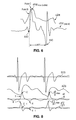
- FIG. 8 shows waveform examples of the following: ECG, ⁇ Z(t), dZ/dt, and d 2 Z/dt 2 ( ⁇ /s 3 ) from the transthoracic approach.
- Fiducial landmarks noted on the dZ/dt waveform are point B, denoting aortic valve opening, point C, denoting dZ/dt max , and point X, denoting aortic valve closure.
- Fiducial landmarks noted on the d 2 Z/dt 2 waveform are point B-1 indicating d 2 Z/dt 2 max and corresponding proximate in time to aortic valve opening; point C-1 corresponding to the first zero crossing and thus dZ/dt max ; and point X-1, corresponding to the second zero crossing and aortic valve closure (point X on the dZ/dt waveform).
- the magnitude, d 2 Z/dt 2 max is noted.
- the terms “comprises,” “comprising,” “includes,” “including,” “has,” “having” or any other variation thereof, are intended to cover a non-exclusive inclusion.
- a process, method, article, or apparatus that comprises a list of elements is not necessarily limited to only those elements but may include other elements not expressly listed or inherent to such process, method, article, or apparatus.
- “or” refers to an inclusive or and not to an exclusive or. For example, a condition A or B is satisfied by any one of the following: A is true (or present) and B is false (or not present), A is false (or not present) and B is true (or present), and both A and B are true (or present).
- the present invention discloses a method and apparatus for the determination of stroke volume (SV) and cardiac output (CO) by transbrachial electrical bioimpedance, wherein the signal source is the brachial artery.
- SV and CO while not sensitive indices of the overall intrinsic force generation capacity, or contractility of the heart muscle, are the best indicators of the overall performance of the heart considered as a muscular pump.
- the apparatus and method disclosed involve the application of a constant magnitude alternating current of high frequency and small amplitude across a segment of a person's upper extremity, and more specifically, the upper arm, otherwise known as the brachium.
- the present invention may also provide for calibrating the transbrachial method and apparatus by determining SV/CO from the transthoracic approach.
- the present invention relates to the acquisition and signal processing of the cardiogenically-induced, pulsatile transbrachial bioimpedance signal for the purpose of SV/CO determination.
- the present invention relates to the measurement of stroke volume (SV) and cardiac output (CO) from the transbrachial method, using the brachial artery as the cardiogenically-induced signal source.
- the transbrachial method is similar to the transthoracic technique for determining SV.
- signal acquisition is effected over a segment of thorax by placement of voltage sensing electrodes 214 at the base of the neck, bilaterally, and voltage sensing electrodes 216 at the lower thorax at the xiphoid level, bilaterally (see FIG. 7 ).
- the transbrachial technique uses a segment of brachium between voltage sensing electrodes 112 / 114 positioned proximate the axilla (arm pit) and junction of the upper and lower arm at the level of the olecranon process of the elbow. (see FIG. 1 ).
- FIG. 1 schematically shows one apparatus embodiment according to the present invention, and its electrical interface with a subject 100 .
- Signal acquisition from the upper arm 102 (brachium) requires application of a constant magnitude alternating current (A.C.) 104 of high frequency and small amplitude to electrodes 106 , 108 that are spaced apart, with one or more electrodes affixed to the skin of the axilla, as well as one or more electrodes placed medially at the level of the antecubital fossa creating a current field.
- the electrodes are applied to the subject's left arm. In other embodiments, the electrodes may be positioned on the right arm.
- the potential difference between the current injecting electrodes or alternating current flow electrodes 106 , 108 is measured by a voltmeter 110 connected to the voltage sensing electrodes 112 , 114 placed within the current field (see FIG. 1 ).
- a baseline impedance between the voltage sensing electrodes 112 , 114 , as well as a change in impedance, ⁇ Z(t) can be measured transbrachially.
- dZ/dt (brachium) results, its peak systolic magnitude being dZ/dt max(brachium) .
- d 2 Z/dt 2 and d 2 Z/dt 2 max are equivalent to the rate of change and peak negative rate of change of dZ/dt and dZ/dt min , respectively.
- dZ/dt max being equivalent to dZ/dt min
- Many different methods of applying the electrodes or electrode arrays to the arm are envisioned, such as spot electrodes, arm band(s) both circumferential and non-circumferential, adhesive strips or other attachment means known in the art.
- an 8 spot-electrode array can be implemented.
- a 4 spot-electrode array placed on the inner, or medial aspect of the upper arm, proximate the brachial artery, can be implemented.
- the voltages measured by the Voltmeter 110 not only contains a signal caused by the AC applied, but may also contain a signal component from which an electrocardiogram (ECG) can be derived.
- ECG electrocardiogram
- the application of filters separates the AC related and ECG related signal components.
- EKG 116 may also be measured by placing EKG electrodes 118 on the patient 100 .
- a 3-lead EKG is shown and EKG is measured by known means.
- the magnitude of the alternating current (A.C.) 104 and voltmeter 110 may be components of an apparatus 120 .
- the apparatus 120 may also include an input device and a processor.
- the input device may be any suitable device that provides information to the apparatus, such as a keyboard.
- the input device may also receive information from external sources, such as the EKG 116 .
- the processor is in communication with the data input device, the alternating current source 104 and electrodes 106 , 108 , and the voltmeter 110 and electrodes 112 , 114 .
- the processor is capable of receiving the information and calculating the stroke volume and cardiac output of the patient 100 .
- the stroke volume and cardiac output of the patient may be displayed on a screen or be sent to other devices via a data output device of the apparatus.
- dZ/dt waveform to the right shows dZ/dt max remaining constant throughout the ejection interval, T LVE .
- Rationale for use of the brachium as an appropriate anatomic site for SV measurement by the bioimpedance technique is as follows.
- A.C. (I) is injected through a segment of upper arm, otherwise known as the brachium, the boundaries of which are the deltoid muscles of the shoulder and axilla, proximally, and the elbow and antecubital fossa, distally, a quasi-static voltage, U 0 , and voltage change, ⁇ U(t), can be measured between the current injecting electrodes.
- the brachial artery is a large artery, continuous with both the subclavian and axillary arteries, and, whereas the left subclavian artery is a major branch of the arch of the thoracic aorta, the right subclavian artery is a branch of the brachiocephalic artery.
- the contents of the upper arm, including connective tissue, bone, nervous tissue, veins, and the brachial artery, comprise an impedance (Z) to current flow.
- Z impedance
- dZ/dt max(brachial) represents the ohmic analog of peak blood acceleration in the brachial artery.
- brachial artery blood velocity is affected by downstream peripheral vasoactivity (vasodilation, vasoconstriction)
- the magnitude of brachial artery blood acceleration is modulated only by beta ( ⁇ ) adrenergic stimulation or depression of the cardiac adrenoceptors (Chemla D, et al. Am J Cardiol 1990; 65:494-500).
- dZ/dt max /Z 0 (1/s 2 ) undergoes square root transformation
- ohmic mean velocity results, ⁇ Z v (t) max /Z 0 (1/s).
- dZ/dt max represents ohmic mean acceleration
- dZ/dt max /Z 0 is herein referred to as the acceleration index (ACI).
- ACI acceleration index
- SV TB V C ⁇ [ ( d 2 ⁇ Z / d t mean 2 Z 0 ) ⁇ 10 - 2 ] 3 ⁇ T LVE equation ⁇ ⁇ 1
- SV TB transbrachial SV (mL); V c(brachium) equals the volume conductor (mL); Z 0 equals the quasi-static transbrachial base impedance (Ohm, ⁇ ); T lve equals left ventricular ejection time (s), and d 2 Z/dt 2 mean equals the mean value of the second time-derivative of the cardiogenically induced transbrachial impedance variation ( ⁇ /s 3 ).
- dZ(t)/dt max the present technique assumes dZ(t)/dt max to represent the ohmic equivalent of the peak acceleration of red blood cells.
- dv/dt max the peak red blood cell acceleration
- dV/dt max the peak rate of change of volume
- the mean value of the second time-derivative of ⁇ Z(t) has certain advantages over processing the first time-derivative (e.g. time to peak values calculated more accurately because of using cube root calculations over square root calculations), which are provided in another preferred embodiment using the transthoracic approach.
- the cube root transformation is thus implemented in the preferred embodiment.
- the signal processing technique comprising part of the invention, implies that the proper designation for the transbrachial approach is correctly stated as Transbrachial Electrical Bioimpedance Cardiovelocimetry or, simply, Transbrachial bioimpedance velocimetry.
- FIGS. 3 a and 3 b show the relationship between the dZ/dt curve and either the dP/dt or d(SpO 2 )/dt curves.
- FIG. 3 a further shows an example where points B and X are apparent on the dZ/dt curve and
- FIG. 3 b shows an example where point B is not detectable, but point X is detectable on the dZ/dt curve.
- the said alternative/obligatory means for determining T lve are those obtained from means such as from the waveform corresponding to the photoplethysmographic pulse oximetry waveform, ⁇ SpO 2 (t), or its first time-derivative, d(SpO 2 )/dt, and/or by the waveform obtained from a non-invasive applanated radial arterial pressure pulse waveform, ⁇ P(t) (radial) , or its first time-derivative, dP/dt (radial) . (see FIG. 4 )
- the said means for determining point B on the transbrachial dZ/dt curve are those methods used for determining T lve when point X on the transbrachial dZ/dt curve, or its first time derivative (d 2 Z/dt 2 ), are identifiable by those skilled in the art of bioimpedance curve analysis.
- point X is not identifiable on the transbrachial dZ/dt curve, or its first time-derivative, d 2 Z/dt 2 , then alternative means for point B detection are necessary.
- said means for point B detection include use of the first time-derivative of the applanated radial pressure waveform tracing, dP/dt (radial) . It will be clear to those skilled in the art of curve analysis, why the aforementioned said means are superior to those disclosed by others, and most recently by Baura et al. (U.S. Pat. No. 6,561,986 B2).
- dZ/dt waveforms such as those shown in FIG. 3 a
- point B and point X are readily distinguishable by one skilled in the art of curve analysis.
- these fiducial landmarks are frequently distorted by motion and ventilation artifacts (especially using the transthoracic approach), as well as by certain disease processes.
- LVET may be more accurately measured by curve analysis of the pulse oximetry and applanation tonometry waveforms ( FIG. 3 b ), or their first time-derivatives. In one embodiment of the invention, either or both methods may be implemented. Of these techniques, applanation tonometry is most likely to demonstrate a dicrotic notch, and, therefore, is considered the preferred technique.
- the points coinciding with the beginning and end of ejection can be readily identified from the first time-derivative curves of both the oximetry and applanation tonometry waveforms; namely, d(SpO 2 )/dt and dP/dt (radial) .
- the best method constitutes computer analysis of the first time-derivatives.
- regression equations for heart rate versus LVET may be implemented.
- Point B on the transbrachial dZ/dt waveform is known to coincide with aortic valve opening, albeit with a time delay.
- Exemplary dZ/dt waveforms demonstrate a distinct change in slope at, or not uncommonly above the zero baseline impedance, followed by a steep, positive linear segment ending at point C, or dZ/dt max .
- dZ/dt max When a distinct change in slope leading to point C is detected at or above the baseline, one skilled in the art of curve analysis can readily identify point B.
- Debski TT et al. Biol Psychol 1993; 36:63-74
- using the transthoracic method despite using fiducial landmarks on the time-derivatives of dZ/dt (i.e.
- the method disclosed herein provides a new and innovative solution for point B detection.
- the new method employs one, or a combination of methods disclosed under determination of LVET; namely, ⁇ SpO 2 (t) and/or ⁇ P(t) (radial) (as shown in FIG. 4 ), or, respectively, their time derivatives, d(SpO 2 )/dt and/or dP/dt (radial) (as shown in FIG.
- the technique of point B detection involves computerized curve fitting and alignment in time of temporal landmark X on the transbrachial dZ/dt curve with the dicrotic notch equivalent of one or both of the measured aforementioned oximetry and pressure curves, and/or preferably with one or both of their first time-derivatives.
- one or both of the first time-derivative curves can be aligned in time with the transbrachial dZ/dt curve, such that the temporal point of the termination of flow, or aortic valve closure (AVC) equivalent on the first derivative oximetry or pressure curves, can be aligned in time with point X of the transbrachial dZ/dt curve.
- AVC aortic valve closure
- Point B coinciding with aortic valve opening (AVO), and the beginning of flow, albeit with a time delay, is identified by determining the temporal point on the transbrachial dZ/dt curve, intersecting, and coinciding in time with the point of onset of flow/pressure on the ⁇ SpO 2 (t)/AP(t) curves, and/or on their first time-derivatives.
- This temporal point is identified as a discreet point at the baseline occurring before the first positive maximum upslope measured from foot of the respective baselines of the ⁇ SpO 2 (t) and/or ⁇ P(t) (radial) curves, and/or from their first time-derivatives ( FIGS. 3 a , 3 b , 4 , 5 , 6 ).
- said means requires alignment in time of the earliest maximum positive peak of dP/dt (dP/dt max ) with point C of the transbrachial dZ/dt curve.
- point B can be identified by applying a perpendicular through, and coinciding in time with the onset at baseline of the first positive deflection of dP/dt, where said perpendicular line must intersect the dZ/dt curve at or above baseline impedance.
- the point of intersection of the perpendicular with the transbrachial dZ/dt curve is designated point B.
- transbrachial d 2 Z/dt 2 max is the measured peak positive deflection of the d 2 Z/dt 2 (d 2 Z/dt 2 max ) curve usually occurring temporally proximate point B on the transbrachial dZ/dt curve.
- ⁇ ⁇ V c ⁇ ( thorax ) C 1 ⁇ ( thorax ) ⁇ [ W ⁇ ( kg ) ⁇ C 2 ] equation ⁇ ⁇ 4
- 0.10 ⁇ C 1(thorax) ⁇ 0.75, wherein C 1 0.25 in the preferred embodiment,
- the SV of the left ventricle can be determined using the transthoracic approach and the mean value of the second time-derivative of the cardiogenically induced transthoracic impedance variation ( ⁇ /s 3 ).
- a tetrapolar spot electrode array can be applied to a person's body. The description of signal acquisition and processing is precisely that described above with respect to FIG. 2 .
- Stroke volume determination by means of the transthoracic (TT) application is implemented by means of the following equation (where, in the general embodiment, the stroke volume (SV) equation is given as):
- Ohmic ⁇ ⁇ mean ⁇ ⁇ velocity ⁇ ⁇ ( 1 ⁇ / ⁇ sec ) [ ( d 2 ⁇ Z / d t mean 2 Z 0 ) TT ⁇ 10 - 2 ] 3 equation ⁇ ⁇ 11
- d 2 Z/dt 2 mean is determined identically as described above with regard to equations 1 and 1a-1g.
- V C ⁇ ( TT ) ⁇ ⁇ ( mL ) [ ( C 1 - C 1 ⁇ Z 0 Z c + Z 0 2 Z c 2 ) ⁇ ( C 2 ⁇ W ⁇ C 3 ) ] equation ⁇ ⁇ 14
- n 4 1 n 1
Abstract
Description
-
- 1. A volume conductor, Vc, which underestimates the intrathoracic blood volume (ITBV) by approximately 15-20%
- 2. The implementation of a square root function for heart rate (H.R.) frequency (i.e. √f0=1/(TRR)0.5=(H.R./60)0.5) which is superfluous and unnecessary.
- 3. A best method in the preferred embodiment for determining left ventricular ejection time, Tlve, is not disclosed.
- 4. A best method in the preferred embodiment for determining point B is not disclosed
- 5. A best method in the preferred embodiment for determining dZ/dtmax, based on the accurate determination of point B, is not disclosed
-
- 1. Stroke volume (SV) and cardiac output (CO) values are not affected by excess, extra-vascular, intrathoracic liquids; namely, pulmonary edema fluid.
- 2. Baseline transbrachial quasi-static impedance, Z0, is not affected by pulmonary (lung) ventilation, thereby obviating the necessity for sophisticated stabilizing adaptive filtering techniques to obtain a steady baseline for measurement of the cardiac-induced transbrachial impedance change, ΔZ(t), and the magnitudes and fiducial landmarks on its first time-derivative, transbrachial dZ/dt and on its second time-derivative, d2Z/dt2.
- 3. The cumbersome and user-unfriendly transthoracic band, or tetrapolar spot-electrode array, is replaced by a circumferential or non-circumferential arm band or bands, an adhesive strip or other appropriate means for positioning the electrodes near the brachial artery containing a bipolar, or alternatively, a tetrapolar spot (or band) electrode array positioned on the medial aspect of the brachium between the axilla (arm pit) and a point distal on the brachium at the level of the olecranon process (elbow).
- 4. With the arm at rest, motion artifacts are minimized as compared to the transthoracic approach, and thus, adaptive filtering techniques are less critical.
- 5. Long-term monitoring of SV/CO in the surgical operating room, or intensive care unit, is facilitated by application of the apparatus to the arm, containing the bipolar, or, alternatively, the tetrapolar montage.
- 6. The bioimpedance signal obtained from the brachium is unaffected by the presence of chest thoracostomy tubes, external pacemaker wires, surgical bandages or appliances, and percutaneously placed central venous access catheters located in the neck or upper chest.
- 7. Without the perturbing influence of pulmonary ventilation, and pulmonary artery and other intrathoracic large vessel venous pulsations, the signal to noise ratio (S/N) relating to those portions the transbrachial dZ/dt and d2Z/dt2 signals pertaining only to left ventricular ejection are substantially higher than that of the transthoracic approach.
where SVTB=transbrachial SV (mL); Vc(brachium) equals the volume conductor (mL); Z0 equals the quasi-static transbrachial base impedance (Ohm, Ω); Tlve equals left ventricular ejection time (s), and d2Z/dt2 mean equals the mean value of the second time-derivative of the cardiogenically induced transbrachial impedance variation (Ω/s3). In a first embodiment:
d 2 Z/dt 2 mean=(dZ/dt max)/TTP m, equation 1a
where TTPm=measured time to peak dZ/dt, defined as the temporal interval from point B to point C (seconds, s) in
d 2 Z/dt 2 mean=(dZ/dt max)/TTP b, equation 1b
where 0.01 s≦TTPb≦0.1 s, such as TTPb=0.06 s. In a third embodiment:
d 2 Z/dt 2 mean=(dZ/dt max)/TTP c, equation 1c
where TTPc=corrected rise time, or time to peak dZ/dt, which is the corrected temporal interval from point B to point C (s). Here, TTPc=(10−a)×[1/(ACI)b]=s; where [1/(ACI)b]=ACI−b; “a” is a negative exponent such as 0>a≧5 or even a=−2; ACI=acceleration index=dZ/dtmax/Z0=1/s2; “b” is an exponent such as 0.1≦−b≦1.0 or even b=0.5; where −b (minus b) is a negative exponent such as 0>−b≧10 or even −b (minus b)=−0.5; and 0.01 s≦TTPc≦0.1 s. For example, in a preferred embodiment, TTPc=(10−2)×[1/(ACI)0.5]=s. In a fourth embodiment:
d 2 Z/dt 2 mean =dZ/dt max /TTP d, equation 1d
where TTPd(s)=(TTPc+TTPm)/A; and 0<A≦5 such as A=2; and 0.01 s≦TTPd≦0.1 s. In a fifth embodiment:
d 2 Z/dt 2 mean =dZ/dt max /TTP e, equation 1e
where TTPc(s)=(TTPc+TTPb)/A; and 0<A≦5 such as A=2; and 0.01 s≦TTPc≦0.1 s. In a sixth embodiment:
d 2 Z/dt 2 mean =dZ/dt max /TTP f, equation 1f
where TTPf=(TTPm+TTPb)/A; and 0<A≦5 such as A=2; and 0.01 s≦TTPf≦0.1 s. In a seventh embodiment:
d 2 Z/dt 2 mean =d 2 Z/dt 2 max /B; equation 1g
where d2Z/dt2 max (Ω/s3)=the maximal systolic upslope extrapolation of dZ/dt, peak first time-derivative of dZ/dt, or systolic peak rate of change of dZ/dt; and 0<B≦10 such as B=2.
-
- Vc(brachium)=C1·[W·C2];
- C1=0<C1≦50,000,
- W=weight in kilograms (kg)
- C2=C3/(BMIn)y
- BMIn=BMIp/C4
- a. 35≦C3≦100 (mL/kg), wherein C3 in the preferred embodiment=70 mL/kg;
- b. BMIn=normalized body mass index (dimensionless), wherein 0.5≦BMIn≦1.0, wherein the preferred embodiment, BMIn=1
- c. BMIp=a person's body mass index=Weight (kg)/Height (meters)2 (kg/m2) where W=a person's weight (kg), and H=a person's height (m).
- d. 15≦C4≦40 kg/m2, wherein C4=ideal body mass index=24 kg/m2 in the preferred embodiment.
- e. 0.25≦y≦1.0, wherein y=0.5 in the preferred embodiment.
- f. 35≦C2≦100, wherein the preferred embodiment, C2=70 mL/kg
-
- 1. dZ/dt waveform analysis: Tlve (LVET) measured across the brachium is defined as the temporal interval from point B, which corresponds to aortic valve opening (AVO), albeit with a time delay, to point X, which coincides in time, albeit with a short time delay, to aortic valve closure (AVC), these time delays dictated by pulse wave velocity.
- 2. d2Z/dt2 waveform analysis: TLVE (LVET) measured from the peak second time-derivative of the transbrachial or transthoracic impedance pulse variation is defined as the temporal interval proximate the peak of the earliest positive systolic deflection of d2Z/dt2 (i.e. d2Z/dt2 max), corresponding proximate in time with point B on the dZ/dt curve and the nadir of the rising foot of ΔZ(t), to, in the usual case, the second zero baseline impedance crossing of d2Z/dt2. To the ejection interval just described, 20 ms (i.e. 0.02 seconds) should be added. The second Zero crossing, following the first zero crossing corresponding to point C (dZ/dtmax), corresponds temporally with point X on the dZ/dt curve. These relationships are better appreciated by inspection of
FIG. 8 . - 3. Pulse Oximetry waveform (ΔSpO2(t)): LVET is defined as the temporal interval (seconds) from the onset of the oximetric pulse at zero baseline, signifying the onset of ejection, albeit with a time delay, to the oximetry wave equivalent of the dicrotic notch, which signifies aortic valve closure, albeit with a time delay, and the end of ejection. The oximetry waveform can be obtained from any appropriate site on, or within the human body, but, in the preferred embodiment, the distal digit of the human finger is deemed most appropriate.
- 4. Applanation Tonometry Pressure Pulse waveform (ΔP(t)(radial)): LVET is defined as the temporal interval (seconds) from the onset of the pressure pulse at zero baseline, signifying the onset of ejection, albeit with a time delay, to the dicrotic notch equivalent, which signifies aortic valve closure, albeit with a time delay, and the end of ejection. In the preferred embodiment, the pressure pulse waveform is obtained from the radial artery at the wrist, but may be obtained from any site on the arm, specifically from either brachial artery.
- 5. Regression Equations for Tlve versus Heart Rate (HR): LVET is determined by Weissler's regression equations: Male: Tlve=−0.0017·HR+0.413; Female: Tlve=−0.0016·HR+0.418.
It should be noted that any of the above methods of LVET determinations can be used solely, or in combination with each other (e.g. average multiple LVET determinations, use one or more determinations that appear to produce better results, etc.).
-
- 1. Methods for determining point B when point X is readily identifiable by one skilled in the art of curve analysis (see
FIG. 3 a).
- 1. Methods for determining point B when point X is readily identifiable by one skilled in the art of curve analysis (see
-
- 2. Method for determining point B when point X is not readily identifiable by one skilled in the art of curve analysis (see
FIG. 6 ):
- 2. Method for determining point B when point X is not readily identifiable by one skilled in the art of curve analysis (see
-
- 1. External calibration of Vc(brachium) by means of the transthoracic method: Determination of Vc(cal).
Where 0.10≦C1(thorax)≦0.75, wherein C1=0.25 in the preferred embodiment,
-
- 2. Determination of SV from the transbrachial approach by means of auto-calibration: A priori determination of C1(brachium) as a mean value for a population, n.
V c(cal) =C 1(brachium) ·[W(kg)·C 2] equation 6
Where, C1 is thus,
C 1(brachium) =V c(cal) /[W(kg)·C 2] equation 7
where, 0≦C1≦50,000, wherein the preferred embodiment C1 is proprietary.
C 1(brachium)(mean)=[(C 1-1 +C 1-2 +C 1-4 + . . . C 1-n)/n] equation 8
Where C1(mean) ideally=C1-1 through C1-n. Thus, SV determination by the transbrachial approach by auto-calibration is given as,
Where:
-
- SV(TT)=stroke volume by the transthoracic approach (mL).
- VC(TT)=Volume conductor (mL), otherwise known as the volume of electrically participating thoracic tissue (VEPT).
-
- TLVE=left ventricular ejection time (seconds, sec, s).
-
- 1.0≦C1≦8.0, wherein the preferred embodiment C1=4.
- Z0 (Ohm, Ω)=the transthoracic base impedance, or static D.C. component of the total transthoracic impedance, Z(t).
- Zc (Ω)=the critical level of base impedance; wherein, 15Ω≦Zc≦25Ω, and wherein the preferred embodiment, Zc=20Ω. For all values of Z0<20Ω, ζ>1.0, and for all values of Z0<20Ω, ζ=1.0.
- 0.10≦C2≦0.75, wherein the preferred embodiment, C2=0.25
- W=weight in kilograms (kg)
-
- 35≦C4≦100 =mL/kg, wherein the preferred embodiment, C4=70 mL/kg.
- BMIN=normalized body mass index (dimensionless), where 0.5≦BMIN≦5.0, wherein the preferred embodiment BMIN=1.0.
- BMIN=BMIp/C5
-
- C5=a person's ideal body mass index (kg/m2), where 10≦C5≦100, wherein the preferred embodiment, C5=24 kg/m2.
- y is an exponent, 0.25≦y≦1.0, wherein the preferred embodiment, y=0.5, where 1/y=equivalent root function, where, 1/y√{square root over (BMIN)}=(BMIN)y.
- 35≦C3≦100, wherein the preferred embodiment, C3=70 mL/kg.
Where:
-
- 1.0≦n1≦10, wherein the preferred embodiment, n1=3.
- 1.0≦n2≦10, wherein the preferred embodiment, n2=2.
- 0<n3≦5, wherein the preferred embodiment, n3=2.
- 0.1≦n4≦1.0, wherein the preferred embodiment, n4=0.333.
-
- TLVE=left ventricular ejection time (seconds, sec).
Wherein as operationally implemented in the preferred embodiment, the stroke volume equation for the transthoracic application is given as,
Claims (26)
Priority Applications (3)
| Application Number | Priority Date | Filing Date | Title |
|---|---|---|---|
| US11/158,521 US7806830B2 (en) | 2004-06-16 | 2005-06-21 | Apparatus and method for determination of stroke volume using the brachial artery |
| PCT/US2005/044671 WO2006063255A2 (en) | 2004-12-08 | 2005-12-08 | Determining of stroke volume using the brachial artery |
| US12/489,335 US7740590B2 (en) | 2004-06-16 | 2009-06-22 | Apparatus and method for determination of stroke volume using the brachial artery |
Applications Claiming Priority (3)
| Application Number | Priority Date | Filing Date | Title |
|---|---|---|---|
| US10/870,281 US7261697B2 (en) | 2004-06-16 | 2004-06-16 | Apparatus for determination of stroke volume using the brachial artery |
| US63461604P | 2004-12-08 | 2004-12-08 | |
| US11/158,521 US7806830B2 (en) | 2004-06-16 | 2005-06-21 | Apparatus and method for determination of stroke volume using the brachial artery |
Related Parent Applications (1)
| Application Number | Title | Priority Date | Filing Date |
|---|---|---|---|
| US10/870,281 Continuation-In-Part US7261697B2 (en) | 2004-06-16 | 2004-06-16 | Apparatus for determination of stroke volume using the brachial artery |
Related Child Applications (1)
| Application Number | Title | Priority Date | Filing Date |
|---|---|---|---|
| US12/489,335 Division US7740590B2 (en) | 2004-06-16 | 2009-06-22 | Apparatus and method for determination of stroke volume using the brachial artery |
Publications (2)
| Publication Number | Publication Date |
|---|---|
| US20060009710A1 US20060009710A1 (en) | 2006-01-12 |
| US7806830B2 true US7806830B2 (en) | 2010-10-05 |
Family
ID=36578625
Family Applications (2)
| Application Number | Title | Priority Date | Filing Date |
|---|---|---|---|
| US11/158,521 Active - Reinstated 2028-06-19 US7806830B2 (en) | 2004-06-16 | 2005-06-21 | Apparatus and method for determination of stroke volume using the brachial artery |
| US12/489,335 Active US7740590B2 (en) | 2004-06-16 | 2009-06-22 | Apparatus and method for determination of stroke volume using the brachial artery |
Family Applications After (1)
| Application Number | Title | Priority Date | Filing Date |
|---|---|---|---|
| US12/489,335 Active US7740590B2 (en) | 2004-06-16 | 2009-06-22 | Apparatus and method for determination of stroke volume using the brachial artery |
Country Status (2)
| Country | Link |
|---|---|
| US (2) | US7806830B2 (en) |
| WO (1) | WO2006063255A2 (en) |
Cited By (24)
| Publication number | Priority date | Publication date | Assignee | Title |
|---|---|---|---|---|
| US8731649B2 (en) | 2012-08-30 | 2014-05-20 | Covidien Lp | Systems and methods for analyzing changes in cardiac output |
| US8977348B2 (en) | 2012-12-21 | 2015-03-10 | Covidien Lp | Systems and methods for determining cardiac output |
| US9060745B2 (en) | 2012-08-22 | 2015-06-23 | Covidien Lp | System and method for detecting fluid responsiveness of a patient |
| US9241646B2 (en) | 2012-09-11 | 2016-01-26 | Covidien Lp | System and method for determining stroke volume of a patient |
| US9357937B2 (en) | 2012-09-06 | 2016-06-07 | Covidien Lp | System and method for determining stroke volume of an individual |
| US9451888B1 (en) | 2015-03-27 | 2016-09-27 | Cordeus, Inc. | Method and apparatus for determination of left ventricular stroke volume and cardiac output using the arteries of the forearm |
| USD788312S1 (en) | 2012-02-09 | 2017-05-30 | Masimo Corporation | Wireless patient monitoring device |
| US9788735B2 (en) | 2002-03-25 | 2017-10-17 | Masimo Corporation | Body worn mobile medical patient monitor |
| US9847002B2 (en) | 2009-12-21 | 2017-12-19 | Masimo Corporation | Modular patient monitor |
| US9913617B2 (en) | 2011-10-13 | 2018-03-13 | Masimo Corporation | Medical monitoring hub |
| US9943269B2 (en) | 2011-10-13 | 2018-04-17 | Masimo Corporation | System for displaying medical monitoring data |
| US10226187B2 (en) | 2015-08-31 | 2019-03-12 | Masimo Corporation | Patient-worn wireless physiological sensor |
| US10524668B2 (en) | 2018-02-05 | 2020-01-07 | Aerobex, Inc. | Method and apparatus for determination of left ventricular stroke volume and cardiac output using the arteries of the forearm by means of integration technique |
| US10617302B2 (en) | 2016-07-07 | 2020-04-14 | Masimo Corporation | Wearable pulse oximeter and respiration monitor |
| US10825568B2 (en) | 2013-10-11 | 2020-11-03 | Masimo Corporation | Alarm notification system |
| US10833983B2 (en) | 2012-09-20 | 2020-11-10 | Masimo Corporation | Intelligent medical escalation process |
| US10912524B2 (en) | 2006-09-22 | 2021-02-09 | Masimo Corporation | Modular patient monitor |
| US11058303B2 (en) | 2012-09-14 | 2021-07-13 | Covidien Lp | System and method for determining stability of cardiac output |
| US11076777B2 (en) | 2016-10-13 | 2021-08-03 | Masimo Corporation | Systems and methods for monitoring orientation to reduce pressure ulcer formation |
| US11109818B2 (en) | 2018-04-19 | 2021-09-07 | Masimo Corporation | Mobile patient alarm display |
| USD974193S1 (en) | 2020-07-27 | 2023-01-03 | Masimo Corporation | Wearable temperature measurement device |
| USD980091S1 (en) | 2020-07-27 | 2023-03-07 | Masimo Corporation | Wearable temperature measurement device |
| USD1000975S1 (en) | 2021-09-22 | 2023-10-10 | Masimo Corporation | Wearable temperature measurement device |
| USD1022729S1 (en) | 2022-12-20 | 2024-04-16 | Masimo Corporation | Wearable temperature measurement device |
Families Citing this family (16)
| Publication number | Priority date | Publication date | Assignee | Title |
|---|---|---|---|---|
| US8938292B2 (en) | 2008-07-31 | 2015-01-20 | Medtronic, Inc. | Estimating cardiovascular pressure and volume using impedance measurements |
| US8406865B2 (en) * | 2008-09-30 | 2013-03-26 | Covidien Lp | Bioimpedance system and sensor and technique for using the same |
| DE102010016172A1 (en) | 2010-03-26 | 2011-09-29 | Medis Medizinische Messtechnik Gmbh | Arrangement and method for non-invasive detection of haemodynamic parameters |
| US10856752B2 (en) * | 2010-12-28 | 2020-12-08 | Sotera Wireless, Inc. | Body-worn system for continuous, noninvasive measurement of cardiac output, stroke volume, cardiac power, and blood pressure |
| ES2398439B1 (en) * | 2011-07-29 | 2014-03-05 | Universitat Politècnica De Catalunya | Method and apparatus for obtaining cardiovascular information by measuring between two extremities |
| US9084585B1 (en) * | 2011-10-06 | 2015-07-21 | Cerner Innovation, Inc. | System and method to classify left ventricular and mitral valve function |
| WO2013081586A1 (en) * | 2011-11-29 | 2013-06-06 | King Saud University | Systems and methods to measure fluid in a body segment |
| US9895069B2 (en) | 2011-11-29 | 2018-02-20 | King Saud University | Systems and methods to measure fluid in a body segment |
| AT514017B1 (en) | 2013-02-22 | 2020-11-15 | Dr Skrabal Falko | Hemodynamic EKG |
| US9498140B2 (en) * | 2014-05-09 | 2016-11-22 | Siemens Medical Solutions Usa, Inc. | Image-based waveform parameter estimation |
| AT516499B1 (en) | 2015-04-22 | 2016-06-15 | Skrabal Falko Dr | Body impedance meter |
| US20190046069A1 (en) * | 2015-07-10 | 2019-02-14 | Bodyport Inc. | Cardiovascular signal acquisition, fusion, and noise mitigation |
| US11696715B2 (en) | 2015-07-10 | 2023-07-11 | Bodyport Inc. | Cardiovascular signal acquisition, fusion, and noise mitigation |
| CN105207635A (en) * | 2015-10-31 | 2015-12-30 | 惠州华阳通用电子有限公司 | Method and device for automatic volume control |
| US20230165474A1 (en) * | 2021-02-26 | 2023-06-01 | Massachusetts Institute Of Technology | Methods to Simulate Metrics of Vascular Function From Clinical Data |
| CN117281494B (en) * | 2023-11-27 | 2024-03-12 | 安徽通灵仿生科技有限公司 | Method and device for identifying signal characteristic points of arterial blood pressure signals |
Citations (29)
| Publication number | Priority date | Publication date | Assignee | Title |
|---|---|---|---|---|
| US3340867A (en) | 1964-08-19 | 1967-09-12 | Univ Minnesota | Impedance plethysmograph |
| US4450527A (en) | 1982-06-29 | 1984-05-22 | Bomed Medical Mfg. Ltd. | Noninvasive continuous cardiac output monitor |
| US4548211A (en) * | 1984-01-12 | 1985-10-22 | Marks Lloyd A | Computer assisted admittance plethysmograph |
| US4562843A (en) | 1980-09-29 | 1986-01-07 | Ljubomir Djordjevich | System for determining characteristics of blood flow |
| US4676253A (en) | 1985-07-18 | 1987-06-30 | Doll Medical Research, Inc. | Method and apparatus for noninvasive determination of cardiac output |
| US4807638A (en) | 1987-10-21 | 1989-02-28 | Bomed Medical Manufacturing, Ltd. | Noninvasive continuous mean arterial blood prssure monitor |
| US4836214A (en) | 1986-12-01 | 1989-06-06 | Bomed Medical Manufacturing, Ltd. | Esophageal electrode array for electrical bioimpedance measurement |
| US4953556A (en) | 1984-12-13 | 1990-09-04 | Evans John M | Method and apparatus for the measurement of thoracic field potentiometry |
| US5103828A (en) | 1988-07-14 | 1992-04-14 | Bomed Medical Manufacturing, Ltd. | System for therapeutic management of hemodynamic state of patient |
| US5178154A (en) | 1990-09-18 | 1993-01-12 | Sorba Medical Systems, Inc. | Impedance cardiograph and method of operation utilizing peak aligned ensemble averaging |
| US5309917A (en) | 1991-09-12 | 1994-05-10 | Drexel University | System and method of impedance cardiography and heartbeat determination |
| US5316004A (en) | 1990-12-28 | 1994-05-31 | Regents Of The University Of Minnesota | Method for vascular impedance measurement |
| US5423326A (en) | 1991-09-12 | 1995-06-13 | Drexel University | Apparatus and method for measuring cardiac output |
| US5469859A (en) | 1992-06-24 | 1995-11-28 | N.I. Medical Ltd. | Non-invasive method and device for collecting measurements representing body activity and determining cardiorespiratory parameters of the human body based upon the measurements collected |
| US5503157A (en) | 1995-03-17 | 1996-04-02 | Sramek; Bohumir | System for detection of electrical bioimpedance signals |
| US5505209A (en) | 1994-07-07 | 1996-04-09 | Reining International, Ltd. | Impedance cardiograph apparatus and method |
| US5685316A (en) | 1996-04-08 | 1997-11-11 | Rheo-Graphic Pte Ltd. | Non-invasive monitoring of hemodynamic parameters using impedance cardiography |
| US5782774A (en) | 1996-04-17 | 1998-07-21 | Imagyn Medical Technologies California, Inc. | Apparatus and method of bioelectrical impedance analysis of blood flow |
| US5791349A (en) | 1996-04-17 | 1998-08-11 | Urohealth, Inc. | Apparatus and method of bioelectrical impedance analysis of blood flow |
| US6016445A (en) | 1996-04-16 | 2000-01-18 | Cardiotronics | Method and apparatus for electrode and transthoracic impedance estimation |
| US6058325A (en) | 1996-04-16 | 2000-05-02 | Cardiotronics | Method and apparatus for high current electrode, transthoracic and transmyocardial impedance estimation |
| US6102869A (en) | 1995-09-12 | 2000-08-15 | Heinemann & Gregori Gmbh | Process and device for determining the cardiac output |
| US6186955B1 (en) | 1998-11-16 | 2001-02-13 | Gail D. Baura | Noninvasive continuous cardiac output monitor |
| US20020193689A1 (en) | 2001-04-03 | 2002-12-19 | Osypka Medical Gmbh | Apparatus and method for determining an approximation of the stroke volume and the cardiac output of the heart |
| EP1304074A2 (en) | 2001-10-11 | 2003-04-23 | Osypka Medical, Inc. | Method and apparatus for determining the left-ventricular ejection time tlev of a heart of a subject |
| US6561986B2 (en) | 2001-01-17 | 2003-05-13 | Cardiodynamics International Corporation | Method and apparatus for hemodynamic assessment including fiducial point detection |
| US6602201B1 (en) | 2000-07-10 | 2003-08-05 | Cardiodynamics International Corporation | Apparatus and method for determining cardiac output in a living subject |
| US6636754B1 (en) | 2000-07-10 | 2003-10-21 | Cardiodynamics International Corporation | Apparatus and method for determining cardiac output in a living subject |
| US6829501B2 (en) | 2001-12-20 | 2004-12-07 | Ge Medical Systems Information Technologies, Inc. | Patient monitor and method with non-invasive cardiac output monitoring |
Family Cites Families (3)
| Publication number | Priority date | Publication date | Assignee | Title |
|---|---|---|---|---|
| US579349A (en) * | 1897-03-23 | Automatic movable dam ob sluiceway gate | ||
| US6322518B1 (en) * | 1993-12-06 | 2001-11-27 | Heska Corporation | Method and apparatus for measuring cardiac output |
| EP1057893B1 (en) * | 1999-06-03 | 2007-05-16 | Ajinomoto Co., Inc. | Method for producing L-arginine |
-
2005
- 2005-06-21 US US11/158,521 patent/US7806830B2/en active Active - Reinstated
- 2005-12-08 WO PCT/US2005/044671 patent/WO2006063255A2/en active Application Filing
-
2009
- 2009-06-22 US US12/489,335 patent/US7740590B2/en active Active
Patent Citations (34)
| Publication number | Priority date | Publication date | Assignee | Title |
|---|---|---|---|---|
| US3340867A (en) | 1964-08-19 | 1967-09-12 | Univ Minnesota | Impedance plethysmograph |
| US4562843A (en) | 1980-09-29 | 1986-01-07 | Ljubomir Djordjevich | System for determining characteristics of blood flow |
| US4450527A (en) | 1982-06-29 | 1984-05-22 | Bomed Medical Mfg. Ltd. | Noninvasive continuous cardiac output monitor |
| US4548211A (en) * | 1984-01-12 | 1985-10-22 | Marks Lloyd A | Computer assisted admittance plethysmograph |
| US4953556A (en) | 1984-12-13 | 1990-09-04 | Evans John M | Method and apparatus for the measurement of thoracic field potentiometry |
| US4676253A (en) | 1985-07-18 | 1987-06-30 | Doll Medical Research, Inc. | Method and apparatus for noninvasive determination of cardiac output |
| US4836214A (en) | 1986-12-01 | 1989-06-06 | Bomed Medical Manufacturing, Ltd. | Esophageal electrode array for electrical bioimpedance measurement |
| US4807638A (en) | 1987-10-21 | 1989-02-28 | Bomed Medical Manufacturing, Ltd. | Noninvasive continuous mean arterial blood prssure monitor |
| US5103828A (en) | 1988-07-14 | 1992-04-14 | Bomed Medical Manufacturing, Ltd. | System for therapeutic management of hemodynamic state of patient |
| US5178154A (en) | 1990-09-18 | 1993-01-12 | Sorba Medical Systems, Inc. | Impedance cardiograph and method of operation utilizing peak aligned ensemble averaging |
| US5316004A (en) | 1990-12-28 | 1994-05-31 | Regents Of The University Of Minnesota | Method for vascular impedance measurement |
| US5309917A (en) | 1991-09-12 | 1994-05-10 | Drexel University | System and method of impedance cardiography and heartbeat determination |
| US5423326A (en) | 1991-09-12 | 1995-06-13 | Drexel University | Apparatus and method for measuring cardiac output |
| US5469859A (en) | 1992-06-24 | 1995-11-28 | N.I. Medical Ltd. | Non-invasive method and device for collecting measurements representing body activity and determining cardiorespiratory parameters of the human body based upon the measurements collected |
| US5505209A (en) | 1994-07-07 | 1996-04-09 | Reining International, Ltd. | Impedance cardiograph apparatus and method |
| US5529072A (en) | 1995-03-17 | 1996-06-25 | Sramek; Bohumir | System for detection of electrical bioimpedance signals |
| US5503157A (en) | 1995-03-17 | 1996-04-02 | Sramek; Bohumir | System for detection of electrical bioimpedance signals |
| US6102869A (en) | 1995-09-12 | 2000-08-15 | Heinemann & Gregori Gmbh | Process and device for determining the cardiac output |
| US5685316A (en) | 1996-04-08 | 1997-11-11 | Rheo-Graphic Pte Ltd. | Non-invasive monitoring of hemodynamic parameters using impedance cardiography |
| US6161038A (en) | 1996-04-08 | 2000-12-12 | Rheo-Graphic Pte Ltd. | Non-invasive monitoring of hemodynamic parameters using impedance cardiography |
| US6016445A (en) | 1996-04-16 | 2000-01-18 | Cardiotronics | Method and apparatus for electrode and transthoracic impedance estimation |
| US6058325A (en) | 1996-04-16 | 2000-05-02 | Cardiotronics | Method and apparatus for high current electrode, transthoracic and transmyocardial impedance estimation |
| US6095987A (en) | 1996-04-17 | 2000-08-01 | Imagyn Medical Techonologies California, Inc. | Apparatus and methods of bioelectrical impedance analysis of blood flow |
| US5791349A (en) | 1996-04-17 | 1998-08-11 | Urohealth, Inc. | Apparatus and method of bioelectrical impedance analysis of blood flow |
| US5782774A (en) | 1996-04-17 | 1998-07-21 | Imagyn Medical Technologies California, Inc. | Apparatus and method of bioelectrical impedance analysis of blood flow |
| US6186955B1 (en) | 1998-11-16 | 2001-02-13 | Gail D. Baura | Noninvasive continuous cardiac output monitor |
| US6602201B1 (en) | 2000-07-10 | 2003-08-05 | Cardiodynamics International Corporation | Apparatus and method for determining cardiac output in a living subject |
| US6636754B1 (en) | 2000-07-10 | 2003-10-21 | Cardiodynamics International Corporation | Apparatus and method for determining cardiac output in a living subject |
| US6561986B2 (en) | 2001-01-17 | 2003-05-13 | Cardiodynamics International Corporation | Method and apparatus for hemodynamic assessment including fiducial point detection |
| US6511438B2 (en) | 2001-04-03 | 2003-01-28 | Osypka Medical Gmbh | Apparatus and method for determining an approximation of the stroke volume and the cardiac output of the heart |
| US20020193689A1 (en) | 2001-04-03 | 2002-12-19 | Osypka Medical Gmbh | Apparatus and method for determining an approximation of the stroke volume and the cardiac output of the heart |
| EP1304074A2 (en) | 2001-10-11 | 2003-04-23 | Osypka Medical, Inc. | Method and apparatus for determining the left-ventricular ejection time tlev of a heart of a subject |
| US20030163058A1 (en) | 2001-10-11 | 2003-08-28 | Osypka Markus J. | Method and apparatus for determining the left-ventricular ejection time TLVE of a heart of a subject |
| US6829501B2 (en) | 2001-12-20 | 2004-12-07 | Ge Medical Systems Information Technologies, Inc. | Patient monitor and method with non-invasive cardiac output monitoring |
Non-Patent Citations (3)
| Title |
|---|
| International Search Report and Written Opinion for International Application No. PCT/US05/20420 mailed Sep. 25, 2006. |
| Moshkovitz Y., et al., Recent Developments in Cardiac Output Determination by Bioimpedance: Comparison with Invasive Cardiac Output and Potential Cardiovascular Applications, Current Opinion in Cardiology, 2004, 19:229-237. |
| Wallace, Arthur W., et al., "Endotracheal Cardiac Output Monitor," Anesthesiology, vol. 92, pp. 178-189, Jan. 2000. |
Cited By (58)
| Publication number | Priority date | Publication date | Assignee | Title |
|---|---|---|---|---|
| US9795300B2 (en) | 2002-03-25 | 2017-10-24 | Masimo Corporation | Wearable portable patient monitor |
| US10219706B2 (en) | 2002-03-25 | 2019-03-05 | Masimo Corporation | Physiological measurement device |
| US11484205B2 (en) | 2002-03-25 | 2022-11-01 | Masimo Corporation | Physiological measurement device |
| US10213108B2 (en) | 2002-03-25 | 2019-02-26 | Masimo Corporation | Arm mountable portable patient monitor |
| US10869602B2 (en) | 2002-03-25 | 2020-12-22 | Masimo Corporation | Physiological measurement communications adapter |
| US9872623B2 (en) | 2002-03-25 | 2018-01-23 | Masimo Corporation | Arm mountable portable patient monitor |
| US10335033B2 (en) | 2002-03-25 | 2019-07-02 | Masimo Corporation | Physiological measurement device |
| US9788735B2 (en) | 2002-03-25 | 2017-10-17 | Masimo Corporation | Body worn mobile medical patient monitor |
| US10912524B2 (en) | 2006-09-22 | 2021-02-09 | Masimo Corporation | Modular patient monitor |
| US10943450B2 (en) | 2009-12-21 | 2021-03-09 | Masimo Corporation | Modular patient monitor |
| US9847002B2 (en) | 2009-12-21 | 2017-12-19 | Masimo Corporation | Modular patient monitor |
| US10354504B2 (en) | 2009-12-21 | 2019-07-16 | Masimo Corporation | Modular patient monitor |
| US11900775B2 (en) | 2009-12-21 | 2024-02-13 | Masimo Corporation | Modular patient monitor |
| US11241199B2 (en) | 2011-10-13 | 2022-02-08 | Masimo Corporation | System for displaying medical monitoring data |
| US11179114B2 (en) | 2011-10-13 | 2021-11-23 | Masimo Corporation | Medical monitoring hub |
| US9943269B2 (en) | 2011-10-13 | 2018-04-17 | Masimo Corporation | System for displaying medical monitoring data |
| US9913617B2 (en) | 2011-10-13 | 2018-03-13 | Masimo Corporation | Medical monitoring hub |
| US11786183B2 (en) | 2011-10-13 | 2023-10-17 | Masimo Corporation | Medical monitoring hub |
| US10925550B2 (en) | 2011-10-13 | 2021-02-23 | Masimo Corporation | Medical monitoring hub |
| US9993207B2 (en) | 2011-10-13 | 2018-06-12 | Masimo Corporation | Medical monitoring hub |
| US10512436B2 (en) | 2011-10-13 | 2019-12-24 | Masimo Corporation | System for displaying medical monitoring data |
| US10149616B2 (en) | 2012-02-09 | 2018-12-11 | Masimo Corporation | Wireless patient monitoring device |
| US10188296B2 (en) | 2012-02-09 | 2019-01-29 | Masimo Corporation | Wireless patient monitoring device |
| US11918353B2 (en) | 2012-02-09 | 2024-03-05 | Masimo Corporation | Wireless patient monitoring device |
| USD788312S1 (en) | 2012-02-09 | 2017-05-30 | Masimo Corporation | Wireless patient monitoring device |
| US11083397B2 (en) | 2012-02-09 | 2021-08-10 | Masimo Corporation | Wireless patient monitoring device |
| US9060745B2 (en) | 2012-08-22 | 2015-06-23 | Covidien Lp | System and method for detecting fluid responsiveness of a patient |
| US9402573B2 (en) | 2012-08-22 | 2016-08-02 | Covidien Lp | System and method for detecting fluid responsiveness of a patient |
| US8731649B2 (en) | 2012-08-30 | 2014-05-20 | Covidien Lp | Systems and methods for analyzing changes in cardiac output |
| US9357937B2 (en) | 2012-09-06 | 2016-06-07 | Covidien Lp | System and method for determining stroke volume of an individual |
| US11445930B2 (en) | 2012-09-11 | 2022-09-20 | Covidien Lp | System and method for determining stroke volume of a patient |
| US10448851B2 (en) | 2012-09-11 | 2019-10-22 | Covidien Lp | System and method for determining stroke volume of a patient |
| US9241646B2 (en) | 2012-09-11 | 2016-01-26 | Covidien Lp | System and method for determining stroke volume of a patient |
| US11058303B2 (en) | 2012-09-14 | 2021-07-13 | Covidien Lp | System and method for determining stability of cardiac output |
| US10833983B2 (en) | 2012-09-20 | 2020-11-10 | Masimo Corporation | Intelligent medical escalation process |
| US11887728B2 (en) | 2012-09-20 | 2024-01-30 | Masimo Corporation | Intelligent medical escalation process |
| US8977348B2 (en) | 2012-12-21 | 2015-03-10 | Covidien Lp | Systems and methods for determining cardiac output |
| US11488711B2 (en) | 2013-10-11 | 2022-11-01 | Masimo Corporation | Alarm notification system |
| US10825568B2 (en) | 2013-10-11 | 2020-11-03 | Masimo Corporation | Alarm notification system |
| US10832818B2 (en) | 2013-10-11 | 2020-11-10 | Masimo Corporation | Alarm notification system |
| US11699526B2 (en) | 2013-10-11 | 2023-07-11 | Masimo Corporation | Alarm notification system |
| US9451888B1 (en) | 2015-03-27 | 2016-09-27 | Cordeus, Inc. | Method and apparatus for determination of left ventricular stroke volume and cardiac output using the arteries of the forearm |
| US11576582B2 (en) | 2015-08-31 | 2023-02-14 | Masimo Corporation | Patient-worn wireless physiological sensor |
| US10226187B2 (en) | 2015-08-31 | 2019-03-12 | Masimo Corporation | Patient-worn wireless physiological sensor |
| US10448844B2 (en) | 2015-08-31 | 2019-10-22 | Masimo Corporation | Systems and methods for patient fall detection |
| US10383527B2 (en) | 2015-08-31 | 2019-08-20 | Masimo Corporation | Wireless patient monitoring systems and methods |
| US10736518B2 (en) | 2015-08-31 | 2020-08-11 | Masimo Corporation | Systems and methods to monitor repositioning of a patient |
| US11089963B2 (en) | 2015-08-31 | 2021-08-17 | Masimo Corporation | Systems and methods for patient fall detection |
| US10617302B2 (en) | 2016-07-07 | 2020-04-14 | Masimo Corporation | Wearable pulse oximeter and respiration monitor |
| US11202571B2 (en) | 2016-07-07 | 2021-12-21 | Masimo Corporation | Wearable pulse oximeter and respiration monitor |
| US11076777B2 (en) | 2016-10-13 | 2021-08-03 | Masimo Corporation | Systems and methods for monitoring orientation to reduce pressure ulcer formation |
| US10524668B2 (en) | 2018-02-05 | 2020-01-07 | Aerobex, Inc. | Method and apparatus for determination of left ventricular stroke volume and cardiac output using the arteries of the forearm by means of integration technique |
| US11109818B2 (en) | 2018-04-19 | 2021-09-07 | Masimo Corporation | Mobile patient alarm display |
| US11844634B2 (en) | 2018-04-19 | 2023-12-19 | Masimo Corporation | Mobile patient alarm display |
| USD980091S1 (en) | 2020-07-27 | 2023-03-07 | Masimo Corporation | Wearable temperature measurement device |
| USD974193S1 (en) | 2020-07-27 | 2023-01-03 | Masimo Corporation | Wearable temperature measurement device |
| USD1000975S1 (en) | 2021-09-22 | 2023-10-10 | Masimo Corporation | Wearable temperature measurement device |
| USD1022729S1 (en) | 2022-12-20 | 2024-04-16 | Masimo Corporation | Wearable temperature measurement device |
Also Published As
| Publication number | Publication date |
|---|---|
| WO2006063255A3 (en) | 2007-04-05 |
| WO2006063255A2 (en) | 2006-06-15 |
| US20090259132A1 (en) | 2009-10-15 |
| US20060009710A1 (en) | 2006-01-12 |
| US7740590B2 (en) | 2010-06-22 |
Similar Documents
| Publication | Publication Date | Title |
|---|---|---|
| US7806830B2 (en) | Apparatus and method for determination of stroke volume using the brachial artery | |
| US7261697B2 (en) | Apparatus for determination of stroke volume using the brachial artery | |
| US6511438B2 (en) | Apparatus and method for determining an approximation of the stroke volume and the cardiac output of the heart | |
| Bernstein et al. | Stroke volume equation for impedance cardiography | |
| US9808168B2 (en) | Method and system for non-invasive measurement of cardiac parameters | |
| US10617322B2 (en) | System, method and apparatus for measuring blood flow and blood volume | |
| US8414498B2 (en) | System, method and apparatus for measuring blood flow and blood volume | |
| CN105832317B (en) | System for measuring cardiac output, stroke volume, heart force and blood pressure | |
| US6228033B1 (en) | Apparatuses and methods for a noninvasive measurement of physiological parameters | |
| Hurwitz et al. | Coherent ensemble averaging techniques for impedance cardiography | |
| Shimazu et al. | Noninvasive measurement of beat-to-beat vascular viscoelastic properties in human fingers and forearms | |
| US9451888B1 (en) | Method and apparatus for determination of left ventricular stroke volume and cardiac output using the arteries of the forearm | |
| Langer et al. | Respiratory-induced hemodynamic changes measured by whole-body multichannel impedance plethysmography. | |
| US20170188962A1 (en) | Physiological monitoring system featuring floormat and handheld sensor | |
| US10524668B2 (en) | Method and apparatus for determination of left ventricular stroke volume and cardiac output using the arteries of the forearm by means of integration technique | |
| US20170188890A1 (en) | Physiological monitoring system featuring floormat and handheld sensor | |
| US20170188944A1 (en) | Physiological monitoring system featuring floormat and handheld sensor | |
| Steiner | Hidden information in three-axial ECG data of normal subjects: Fractal dimensions of corresponding points from successive QRS loops as a potential sport and age dependent marker | |
| Buell | Impedance cardiography and plethysmography | |
| Solà et al. | Wearable PWV technologies to measure Blood Pressure: getting rid of brachial cuffs | |
| Karpov et al. | Preeclampsia Amplitude-time Characteristics for ΔZ/Δt Curve | |
| SENGTHIPPHANY | HEART RATE VARIABILITY ANALYSIS FROM PHOTOPLETHYSMOGRAPHY DURING RESTING AND EXERCISE |
Legal Events
| Date | Code | Title | Description |
|---|---|---|---|
| AS | Assignment |
Owner name: CORDEUS, INC., CALIFORNIA Free format text: ASSIGNMENT OF ASSIGNORS INTEREST;ASSIGNOR:BERNSTEIN, DONALD P.;REEL/FRAME:016648/0162 Effective date: 20050904 |
|
| FEPP | Fee payment procedure |
Free format text: PETITION RELATED TO MAINTENANCE FEES GRANTED (ORIGINAL EVENT CODE: PMFG); ENTITY STATUS OF PATENT OWNER: SMALL ENTITY Free format text: PETITION RELATED TO MAINTENANCE FEES FILED (ORIGINAL EVENT CODE: PMFP); ENTITY STATUS OF PATENT OWNER: SMALL ENTITY |
|
| REMI | Maintenance fee reminder mailed | ||
| LAPS | Lapse for failure to pay maintenance fees | ||
| REIN | Reinstatement after maintenance fee payment confirmed | ||
| PRDP | Patent reinstated due to the acceptance of a late maintenance fee |
Effective date: 20141125 |
|
| FP | Lapsed due to failure to pay maintenance fee |
Effective date: 20141005 |
|
| FPAY | Fee payment |
Year of fee payment: 4 |
|
| STCF | Information on status: patent grant |
Free format text: PATENTED CASE |
|
| FEPP | Fee payment procedure |
Free format text: 7.5 YR SURCHARGE - LATE PMT W/IN 6 MO, SMALL ENTITY (ORIGINAL EVENT CODE: M2555) |
|
| MAFP | Maintenance fee payment |
Free format text: PAYMENT OF MAINTENANCE FEE, 8TH YR, SMALL ENTITY (ORIGINAL EVENT CODE: M2552) Year of fee payment: 8 |
|
| MAFP | Maintenance fee payment |
Free format text: PAYMENT OF MAINTENANCE FEE, 12TH YR, SMALL ENTITY (ORIGINAL EVENT CODE: M2553); ENTITY STATUS OF PATENT OWNER: SMALL ENTITY Year of fee payment: 12 |