US7809183B2 - Gaze manipulation - Google Patents
Gaze manipulation Download PDFInfo
- Publication number
- US7809183B2 US7809183B2 US10/681,007 US68100703A US7809183B2 US 7809183 B2 US7809183 B2 US 7809183B2 US 68100703 A US68100703 A US 68100703A US 7809183 B2 US7809183 B2 US 7809183B2
- Authority
- US
- United States
- Prior art keywords
- occluded
- scan line
- pixel
- pair
- computing
- Prior art date
- Legal status (The legal status is an assumption and is not a legal conclusion. Google has not performed a legal analysis and makes no representation as to the accuracy of the status listed.)
- Expired - Fee Related, expires
Links
Images


Classifications
-
- H—ELECTRICITY
- H04—ELECTRIC COMMUNICATION TECHNIQUE
- H04N—PICTORIAL COMMUNICATION, e.g. TELEVISION
- H04N7/00—Television systems
- H04N7/14—Systems for two-way working
- H04N7/141—Systems for two-way working between two video terminals, e.g. videophone
- H04N7/142—Constructional details of the terminal equipment, e.g. arrangements of the camera and the display
- H04N7/144—Constructional details of the terminal equipment, e.g. arrangements of the camera and the display camera and display on the same optical axis, e.g. optically multiplexing the camera and display for eye to eye contact
-
- G—PHYSICS
- G06—COMPUTING; CALCULATING OR COUNTING
- G06T—IMAGE DATA PROCESSING OR GENERATION, IN GENERAL
- G06T7/00—Image analysis
- G06T7/30—Determination of transform parameters for the alignment of images, i.e. image registration
-
- G—PHYSICS
- G06—COMPUTING; CALCULATING OR COUNTING
- G06T—IMAGE DATA PROCESSING OR GENERATION, IN GENERAL
- G06T7/00—Image analysis
- G06T7/50—Depth or shape recovery
- G06T7/55—Depth or shape recovery from multiple images
- G06T7/593—Depth or shape recovery from multiple images from stereo images
-
- G—PHYSICS
- G06—COMPUTING; CALCULATING OR COUNTING
- G06T—IMAGE DATA PROCESSING OR GENERATION, IN GENERAL
- G06T7/00—Image analysis
- G06T7/97—Determining parameters from multiple pictures
Definitions
- the invention relates generally to image processing, and more particularly to gaze manipulation using image processing.
- Digital video cameras are useful in both consumer and professional contexts. Generally, digital video cameras capture sequences of digital images, which may then be transferred to a computer system for display or processing or to storage device for storage.
- One specific practice employs a digital video camera in a video conferencing application.
- an image sequence depicting a conference participant is transmitted to one or more other participants.
- image sequences depicting the other participants are transmitted to the first participant's display device. In this manner, each participant can view an interactive video of the other participants during the conference.
- a single video camera is focused on a conference participant, who views the other participants in a video window in his or her display device.
- the video camera is commonly mounted on or near the display of a computer or television system in an attempt to minimize the angle between the camera and the video window. Minimizing this angle can enhance the illusion that the participant is looking into the camera instead of at the video window in the display device.
- the angle is never really eliminated and in fact can remain significant, particularly when the camera is close to the participant.
- the other participants receive a display of the top or side of the first participant's head, instead of a straight-on view of the first participant's face.
- these problems may be resolved by a physical camera positioned in the center of the display window, such that the participant's gaze and the camera's axis are aligned—envision a video display with a hole drilled in the middle of it in which to mount the camera.
- a physical camera positioned in the center of the display window, such that the participant's gaze and the camera's axis are aligned—envision a video display with a hole drilled in the middle of it in which to mount the camera.
- a subject sitting in view of two horizontally positioned stereo cameras may be able to view a doorknob behind and slightly to the side of the subject's head, while the second camera cannot view the doorknob because the subject's head occludes the doorknob from the second camera's view.
- the difficulty of reconstructing such occluded regions in the cyclopean image often results in a “halo” effect around the subject's head as well as other artifacts in the image.
- Implementations described and claimed herein address these problems with a multi-layer graph for dense stereo dynamic programming to improve processing of occluded regions.
- Use of a multi-layer graph for dense stereo dynamic programming allows an algorithm to distinguish between stereo disparities caused by occlusion and disparities caused by non-fronto-parallel surfaces. This distinction can be leveraged to reduce the occlusion effects, such as “halos”.
- anisotropic smoothing may be used to improve scan line matching.
- temporal background layer maintenance may be used to reduce temporal artifacts.
- articles of manufacture are provided as computer program products.
- One implementation of a computer program product provides a computer program storage medium readable by a computer system and encoding a computer program.
- Another implementation of a computer program product may be provided in a computer data signal embodied in a carrier wave by a computing system and encoding the computer program.
- the computer program product encodes a computer program for executing on a computer system a computer process that computes a minimum cost path in a stereo disparity model between a scan line of a first image and a corresponding scan line of a second image of a stereo image pair.
- the stereo disparity model distinguishes between non-fronto-parallel matched pixels in each scan line and occluded pixels in each scan line.
- a method computes a minimum cost path in a stereo disparity model between a scan line of a first image and a corresponding scan line of a second image of a stereo image pair.
- the stereo disparity model distinguishes between non-fronto-parallel matched pixels in each scan line and occluded pixels in each scan line.
- a system provides a dynamic programming module computing a minimum cost path in a stereo disparity model between a scan line of a first image and a corresponding scan line of a second image of a stereo image pair.
- the stereo disparity model distinguishes between non-fronto-parallel matched pixels in each, scan line and occluded pixels in each scan line.
- FIG. 1 illustrates an exemplary system for generating a cyclopean virtual image with gaze manipulation.
- FIG. 2 illustrates an exemplary video conferencing system configuration 200 for generating a cyclopean virtual image with gaze manipulation.
- FIG. 3 illustrates stereo disparity as a function of left and right epipolar lines L and R, which are defined in terms of pixel coordinates m and n, respectively.
- FIG. 4 illustrates disparity and cyclopean axes overlaid on the L and R axes.
- FIG. 5 illustrates an exemplary five-move disparity process model.
- FIGS. 6 , 7 , and 8 combine to represent an exemplary three-plane representation of the five-move disparity model.
- FIG. 9 illustrates an exemplary stereo disparity graph for matched points.
- FIG. 10 illustrates an exemplary stereo disparity graph for occluded points.
- FIG. 11 illustrates exemplary operations for performing gaze manipulation.
- FIG. 12 illustrates an exemplary four-move disparity process model.
- FIGS. 13 , 14 , and 15 combine to represent a four-plane representation of the four-move disparity model.
- FIG. 16 illustrates an exemplary system useful for implementing an embodiment of the present invention.
- a multi-layer graph for dense stereo dynamic programming can improve synthesis of cyclopean virtual images by distinguishing between stereo disparities causes by occlusion and disparities caused by non-fronto-parallel surfaces. This distinction can be leveraged to reduce the occlusion effects, such as “halos”.
- occlusion refers to an image region that is captured by one camera but is not captured by a second camera because of an obstruction in the second camera's view (e.g., a video conference participant's head occluding a region of the background from the second camera's view).
- a fronto-parallel surface refers to a surface that is substantially parallel to an axis connecting the left and right cameras. The axis may be referred to as the “baseline”.
- a non-fronto-parallel surface slants away from one camera or the other. Distinguishing at least between these two types of disparities allows improved matching of left and right pixel data, which increases the amount of correct pixel information used in constructing the cyclopean virtual image and minimizes occlusion artifacts.
- FIG. 1 illustrates an exemplary system 100 for generating a cyclopean virtual image with gaze manipulation.
- a left image 102 is captured by a camera mounted on the right side of the video display, as seen by the user.
- a right image 104 is captured by a camera mounted on the left side of the video display, as seen by the user.
- the left and right images 102 and 104 are input to a dynamic programming module 106 , which generates a stereo disparity graph for each corresponding pair of epipolar lines of the images 102 and 104 .
- a three-plane model for the dynamic programming is used, although other graphs may be employed, such as a four-plane model, etc.
- the stereo disparity graph generated by the dynamic programming module is input to a cyclopean virtual image generator 108 , which uses pixel characteristics of corresponding pixels associated with a minimum cost path in the stereo disparity graph to generate the cyclopean virtual image 110 with gaze correction.
- the cyclopean virtual image 110 shows the user as appearing to look directly into the camera.
- FIG. 2 illustrates an exemplary video conferencing system configuration 200 for generating a cyclopean virtual image with gaze manipulation.
- a computer system 202 is coupled to a video display 204 having two cameras 206 and 208 mounted on either side of the video display 204 .
- a video window 210 displays a remote participant on the other end of the video conference session.
- the user In a configuration having only a single camera, the user typically focus his or her eyes on the video window 210 , while the single camera captures images of the user from one side of the other.
- the captured images sent to the remote participant are primarily a side view of the user's head, not a straight-on view of the user's face.
- the illustrated configuration allows generation of a cyclopean virtual image from the captured left and right images of the user.
- the cyclopean virtual image generation synthesizes the cyclopean virtual image from a stereo disparity graph representing the disparity field between corresponding left and right images. Furthermore, the dynamic programming applied to the disparity graph distinguishes between disparities caused by occlusion and disparities caused by non-fronto-parallel surfaces in the view field.
- the cameras may be in alternative orientations, such as at the top and bottom of the video display.
- one configuration may include four cameras, each placed at a corner of the video display.
- each image contains color pixels in three color channels, such that L m ,R n ⁇ 3 .
- L m ,R n ⁇ f there may be other features, such that L m ,R n ⁇ f , where f is an integer.
- groups of pixels may be filtered to obtain improved invariance to illumination variations or non-uniform camera sensitivities.
- the cyclopean virtual image Î is constructed from a set of cyclopean epipolar lines stacked line-by-line to form the resulting cyclopean image.
- FIG. 3 illustrates stereo disparity as a function of left and right epipolar lines L and R, which are defined in terms of pixel coordinates m and n, respectively.
- a diagram 300 shows an axis 302 , representing a sequence of positions along a left epipolar line L, and another axis 304 representing a sequence of positions along a right epipolar line R.
- a minimum cost path 306 indicates matches between pixels in given sequential positions in L with pixels in given sequential positions in R. For example, pixel 1 of L matches pixel 1 of R, as shown by point 308 . In contrast, pixel 3 of L matches pixel 2 of R, as shown by point 310 .
- the disparity associated with a point 310 on the minimum cost path 306 is defined as the orthogonal distance of the point from a virtual scan line 312 (or zero disparity axis or zero parallax axis).
- the disparity of the point 308 is zero, whereas the disparity d of the point 310 is shown by line 314 . (As suggested by the disparity axis of FIG. 4 , the disparity of point 310 is “ ⁇ 1”.)
- the minimum cost path 306 represents a two-dimensional profile of a scan line of the virtual image, where pixels with a greater absolute value of disparity (e.g., point 310 , which has a negative disparity relative to the zero parallax line 312 ) are closer to the virtual cyclopean camera—e.g., the video subject—than pixels with a lower absolute value of disparity (e.g., point 316 , which has a zero disparity relative to the zero parallax line 312 ), which are deemed farther away from the virtual cyclopean camera—e.g., the background.
- Stacking a set of these two-dimensional profiles, which correspond to individual cyclopean epipolar lines, can yield a three-dimensional profile surface of the image subject.
- a matching cost function may be used to determine the minimum cost path in a stereo disparity graph.
- a variety of matching cost functions may be employed to compute the matching two pixels.
- processing individual epipolar line pairs independently can cause visible “streaky” artifacts in the output disparity graph. Therefore, by using neighborhood windows in computing the cost of matching two pixels, the “independence” of the scan lines can be compromised, thereby reducing streaky artifacts.
- a windowed Normalized Sum of Squared Differences (SSD) matching function is used to compute the matching cost M(l,r) for every pair of pixels along corresponding epipolar lines:
- M ssd ⁇ ( l , r ) M ′ ⁇ ( l , r ) 2 ⁇ ⁇ with ( 1 )
- M ′ ⁇ ( l , r ) ⁇ ⁇ ⁇ ⁇ [ ( I p l + ⁇ l - I _ p l l ) - ( I p r + ⁇ r - I _ p r r ) ] 2 ⁇ ⁇ ⁇ ⁇ ⁇ ( I p l + ⁇ l - I _ p l l ) 2 + ⁇ ⁇ ⁇ ⁇ ( I p r + ⁇ r - I _ p r r ) 2 ( 2 )
- ⁇ is an n ⁇ m generic template patch centered at the origin of the coordinate system
- p l and p r are pixel positions (2-vectors) in the left and right images, respectively
- ⁇ is a variable 2D displacement
- NCC Normalized Cross-Correlation
- M ncc ⁇ ( l , r ) 1 - M ′ ⁇ ( l , r ) 2 ⁇ ⁇
- M ′ ⁇ ( l , r ) ⁇ ⁇ ⁇ ⁇ ⁇ ( I p l + ⁇ l - I _ p l l ) ⁇ ( I p r + ⁇ r - I _ p r r ) ⁇ ⁇ ⁇ ⁇ ( I p l + ⁇ l - I _ p l l ) 2 ⁇ ⁇ ⁇ ⁇ ⁇ ( I p r + ⁇ r - I _ p r r ) 2 ( 4 ) is the correlation coefficient.
- Other matching cost functions may also be used, including without limitation shiftable window approaches (e.g., using 3 ⁇ 3 pixel windows or larger) or rectangular window approaches (e.g., using 3 ⁇ 7 windows).
- FIG. 4 illustrates disparity and cyclopean axes overlaid on the L and R axes to show an exemplary stereo disparity graph 400 .
- a disparity vector d in cyclopean coordinates k along the cyclopean axis 404 can be graphed into the pixel coordinates m and n.
- the bold line marks the minimum cost path 406 in the stereo disparity graph 400 .
- a diagonal line on the minimum cost path 406 represents matched pixels.
- horizontal and vertical lines are considered to indicate at least either occluded pixels or matched pixels of non-fronto-parallel surfaces.
- Non-fronto-parallel surfaces cause multiple pixels from one camera image to match with a single pixel in the other camera image, thereby inducing a horizontal or vertical line in the stereo disparity graph.
- FIG. 5 illustrates an exemplary 5-move disparity process model 500 .
- the points 502 , 504 , 506 , and 508 represent possible pixels in the stereo disparity graph, such that the diagonal axis 510 represents a diagonal move 512 between pixels in a stereo disparity graph.
- the horizontal axis 514 represents a horizontal move between pixels in a stereo disparity graph and the vertical axis 516 represents a horizontal move between pixels in a stereo disparity graph.
- FIG. 5 illustrates a 5-move disparity process model, although a 4 move model may also be employed.
- FIGS. 6 , 7 , and 8 combine to represent a 3-plane representation of the 5-move disparity model, but they are split out into separate figures for clarity.
- the 5 move model applies to moves between adjacent pixels in the stereo disparity graph.
- three planes are used: a left-occluded plane L, a matched plane M, and a right-occluded plane R.
- FIG. 6 the moves from an occluded plane to the matched plane are shown (from empty circle to filled circle) in model portion 600 .
- a cost penalty of ⁇ is applied to these moves.
- FIG. 7 the moves 700 and 702 from the matched plane to an occluded plane are shown (from empty circle to filled circle) in model portion 704 .
- a cost penalty of ⁇ is applied to these moves.
- the moves 706 and 708 from one pixel in an occluded plane to another pixel in the same occluded plane are shown (from empty circle to filled circle) in the model portion 704 .
- a cost penalty of ⁇ is applied to these moves.
- ⁇ is set to 0.5 and ⁇ is set to 1.0, although other value combinations are also contemplated.
- FIG. 8 the moves from one pixel in the matched plane to another pixel in the matched plane are shown (from empty circle to filled circle) in the model portion 800 . No cost penalty is applied to these moves.
- the 3-plane model provides a basis for altering the individual costs to distinguish between different types of moves. For example, biasing the penalty costs against inter-plane moves tends to keep runs of occluded or non-occluded pixels together, thus reducing most of the inaccuracies in the reconstruction of occlusions and disparities. Also, logically impossible moves, such as the direct transition between left and right occlusions are prohibited simply by removing certain transitions from the set of allowed transitions in the 3-plane graph.
- C L ⁇ ( l , r ) min ⁇ ⁇ C L ⁇ ( l , r - 1 ) + ⁇ C M ⁇ ( l , r - 1 ) + ⁇ ( 6 )
- C M ⁇ ( l , r ) M ⁇ ( l , r ) + min ⁇ ⁇ C M ⁇ ( l - 1 , r ) C L ⁇ ( l - 1 , r ) + ⁇ C R ⁇ ( l - 1 , r ) + ⁇ C M ⁇ ( l , r - 1 ) C L ⁇ ( l , r - 1 ) + ⁇ C R ⁇ ( l , r - 1 ) + ⁇ C M ⁇ ( l - 1 , r - 1 ) C L ⁇ ( l - 1 ) + ⁇ C R ⁇ ( l , r - 1 ) + ⁇
- the minimum cost path is determined for the scan line pair.
- the matching cost computation and the dynamic programming are repeated for each scan line pair in the stereo images.
- the synthesis of the cyclopean virtual view can be done for each scan line by taking a point p on the minimum cost path, taking the colors of the corresponding pixels p l and p r in the left and right scan lines, averaging them together, and projecting the newly obtained pixel orthogonally to the virtual image plane into the virtual image point p v .
- FIG. 9 illustrates an exemplary stereo disparity graph for matched points.
- a stereo disparity graph 900 shows an axis 902 , representing a sequence of positions along a left scan line L, and another axis 904 representing a sequence of positions along a right scan line R.
- the minimum cost path 906 indicates minimum cost matches between pixels in given sequential positions in L with pixels in given sequential positions in R.
- the disparity associated with a point on the minimum cost path 906 is defined as the orthogonal distance of the point from a virtual scan line 908 .
- a matched point p is projected orthogonally onto its corresponding point p v on the virtual scan line 908 to designate the position of the corresponding cyclopean virtual image pixel on the virtual scan line.
- the pixel value of the virtual pixel p v is the average of the corresponding pixels p l and p r .
- FIG. 10 illustrates an exemplary stereo disparity graph for occluded points.
- a stereo disparity graph 1000 shows an axis 1002 , representing a sequence of positions along a left scan line L, and another axis 1004 representing a sequence of positions along a right scan line R.
- the minimum cost path 1006 indicates minimum cost matches between pixels in given sequential positions in L with pixels in given sequential positions in R.
- the disparity associated with a point on the minimum cost path 1006 is defined as the orthogonal distance of the point from a virtual scan line 1008 .
- An occluded point p on the continuation 1010 of the background (with the same disparity) is projected orthogonally onto its corresponding point p v on the virtual scan line 1008 . Because p represents a pixel within a left occlusion in this illustration, the pixel value of p v is the same as that of the corresponding point p r on the right view only.
- FIG. 11 illustrates exemplary operations for performing gaze manipulation.
- a receipt operation 1100 receives the stereo images from the stereo cameras.
- a computation operation 1102 computes the matching cost for each pixel of the epipolar line pair.
- a filtering operation 1104 filters the matching costs to reduce streaky artifacts caused by scan line independence.
- a dynamic programming operation 1106 alters the initially computed individual costs for each pixel pair to designate different types of moves and therefore different types of disparities (e.g., occlusion disparities versus non-fronto-parallel disparities). Based on the altered costs, a minimum cost path is identified in a path operation 1108 .
- An imaging operation 1110 determines the cyclopean virtual scan line based on the minimum cost path in the stereo disparity graph.
- FIGS. 5-8 address a five-move, three-plane disparity model
- other models may also be employed.
- a four-move, four-plane model can prove as reliable and easier to use.
- every possible path through the cost space has the same length (i.e., the same Manhattan distance between the opposite corners of the cost space), thus making the comparison of path costs more meaningful.
- the removal of the diagonal move makes the model symmetrical and thus more suitable for a possible probabilistic formulation.
- FIG. 12 illustrates an exemplary four-move disparity process model 1200 .
- the points 1202 , 1204 , 1206 , and 1208 represent possible pixels in the stereo disparity graph, such that the diagonal axis 1210 a zero-disparity axis in a stereo disparity graph.
- no diagonal move is modeled.
- the horizontal axis 1214 represents a horizontal move between pixels in a stereo disparity graph and the vertical axis 1216 represents a horizontal move between pixels in a stereo disparity graph.
- FIG. 12 illustrates a four-move disparity process model.
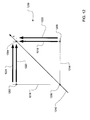
- FIGS. 13 , 14 , and 15 combine to represent a four-plane representation of the four-move disparity model, but they are split out into separate figures for clarity.
- the four-move model applies to moves between adjacent pixels in the stereo disparity graph.
- four planes are used: a left-occluded plane L O , a left matched plane L M , a right matched plane R M , and a right-occluded plane R O .
- a typical “matched” move which in a five-move model would involve a diagonal move, would involve two matched moves, one vertical and one horizontal in a 2D graph or a two-move oscillation between two adjacent matched planes (e.g., from L M to R M and back to L M ).
- FIG. 13 the moves within individual planes are shown (from empty circle to filled circle) in model portion 1300 .
- logically impossible moves such as the direct transition between left and right occlusions are prohibited simply by removing certain transitions from the set of allowed transitions in the four-plane graph.
- a cost penalty of ⁇ is applied to the moves with the occluded planes L O and R O , and a cost penalty of ⁇ +M(l,r) for moves within the matched planes L M and R M .
- FIG. 14 the moves between an occluded plane and an adjacent matched plane are shown (from empty circle to filled circle) in model portion 1400 .
- a cost penalty of ⁇ +M(l,r) is applied to moves from an occluded plane to an adjacent matched plane, a cost penalty of ⁇ is applied to moves from a matched plane to an adjacent occluded plane, and a cost penalty of M(l,r) is applied to moves between matched planes.
- FIG. 15 the moves between an occluded plane and a non-adjacent matched plane are shown (from empty circle to filled circle) in model portion 1500 .
- a cost penalty of ⁇ +M(l,r) is applied to moves from an occluded plane to a non-adjacent matched plane, and a cost penalty of ⁇ is applied to moves from a matched plane to a non-adjacent occluded plane.
- ⁇ is set to 0.5
- ⁇ is set to 1.0
- ⁇ is set to 0.25, although other value combinations are also contemplated.
- C L O ⁇ ( l , r ) min ⁇ ⁇ C L O ⁇ ( l , r - 1 ) + ⁇ C L M ⁇ ( l , r - 1 ) + ⁇ C R M ⁇ ( l , r - 1 ) + ⁇ ( 9 )
- C L M ⁇ ( l , r ) M ⁇ ( l , r ) + min ⁇ ⁇ C L M ⁇ ( l , r - 1 ) + ⁇ C R M ⁇ ( l , r - 1 ) C L O ⁇ ( l , r - 1 ) + ⁇ C R O ⁇ ( l , r - 1 ) + ⁇ ( 10 )
- C R M ⁇ ( l , r ) M ⁇ ( l , r ) + min ⁇ ⁇ C L M ⁇ ( l - 1 , r ) C R M ⁇
- the minimum cost path is determined for the scan line pair.
- the matching cost computation and the dynamic programming are repeated for each scan line pair in the stereo images.
- the synthesis of the cyclopean virtual view can be done for each scan line by taking a point p on the minimum cost path, taking the colors of the corresponding pixels p l and p r in the left and right scan lines, averaging them together, and projecting the newly obtained pixel orthogonally to the virtual image plane into the virtual image point p v .
- the exemplary hardware and operating environment of FIG. 16 for implementing the invention includes a general purpose computing device in the form of a computer 20 , including a processing unit 21 , a system memory 22 , and a system bus 23 that operatively couples various system components include the system memory to the processing unit 21 .
- a processing unit 21 There may be only one or there may be more than one processing unit 21 , such that the processor of computer 20 comprises a single central-processing unit (CPU), or a plurality of processing units, commonly referred to as a parallel processing environment.
- the computer 20 may be a conventional computer, a distributed computer, or any other type of as computer; the invention is not so limited.
- the system bus 23 may be any of several types of bus structures including a memory bus or memory controller, a peripheral bus, and a local bus using any of a variety of bus architectures.
- the system memory may also be referred to as simply the memory, and includes read only memory (ROM) 24 and random access memory (RAM) 25 .
- ROM read only memory
- RAM random access memory
- a basic input/output system (BIOS) 26 containing the basic routines that help to transfer information between elements within the computer 20 , such as during start-up, is stored in ROM 24 .
- a number of program modules may be stored on the hard disk, magnetic disk 29 , optical disk 31 , ROM 24 , or RAM 25 , including an operating system 35 , one or more application programs 36 , other program modules 37 , and program data 38 .
- a user may enter commands and information into the personal computer 20 through input devices such as a keyboard 40 and pointing device 42 .
- Other input devices may include a microphone, joystick, game pad, satellite dish, scanner, or the like.
- These and other input devices are often connected to the processing unit 21 through a serial port interface 46 that is coupled to the system bus, but may be connected by other interfaces, such as a parallel port, game port, or a universal serial bus (USB).
- a monitor 47 or other type of display device is also connected to the system bus 23 via an interface, such as a video adapter 48 .
- computers typically include other peripheral output devices (not shown), such as speakers and printers.
- the computer 20 may operate in a networked environment using logical connections to one or more remote computers, such as remote computer 49 . These logical connections are achieved by a communication device coupled to or a part of the computer 20 ; the invention is not limited to a particular type of communications device.
- the remote computer 49 may be another computer, a server, a router, a network PC, a client, a peer device or other common network node, and typically includes many or all of the elements described above relative to the computer 20 , although only a memory storage device 50 has been illustrated in FIG. 16 .
- the logical connections depicted in FIG. 16 include a local-area network (LAN) 51 and a wide-area network (WAN) 52 .
- LAN local-area network
- WAN wide-area network
- Such networking environments are commonplace in office networks, enterprise-wide computer networks, intranets and the Internal, which are all types of networks.
- the computer 20 When used in a LAN-networking environment, the computer 20 is connected to the local network 51 through a network interface or adapter 53 , which is one type of communications device.
- the computer 20 When used in a WAN-networking environment, the computer 20 typically includes a modem 54 , a type of communications device, or any other type of communications device for establishing communications over the wide area network 52 .
- the modem 54 which may be internal or external, is connected to the system bus 23 via the serial port interface 46 .
- program modules depicted relative to the personal computer 20 may be stored in the remote memory storage device. It is appreciated that the network connections shown are exemplary and other means of and communications devices for establishing a communications link between the computers may be used.
- a dynamic programming module may be incorporated as part of the operating system 35 , application programs 36 , or other program modules 37 .
- the stereo disparity graph data, matching costs, altered costs, and cyclopean virtual image data may be stored as program data 38 .
- the embodiments of the invention described herein are implemented as logical steps in one or more computer systems.
- the logical operations of the present invention are implemented (1) as a sequence of processor-implemented steps executing in one or more computer systems and (2) as interconnected machine modules within one or more computer systems.
- the implementation is a matter of choice, dependent on the performance requirements of the computer system implementing the invention. Accordingly, the logical operations making up the embodiments of the invention described herein are referred to variously as operations, steps, objects, or modules.
Abstract
Description
where Ω is an n×m generic template patch centered at the origin of the coordinate system; pl and pr are pixel positions (2-vectors) in the left and right images, respectively; and δ is a variable 2D displacement vector. The “bar” above a variable (e.g., Ī) represents the mean operator.
is the correlation coefficient. Other matching cost functions may also be used, including without limitation shiftable window approaches (e.g., using 3×3 pixel windows or larger) or rectangular window approaches (e.g., using 3×7 windows).
C R(i,0)=iα (5)
and the forward step of the dynamic programming proceeds as follows:
wherein M(l,r) is the cost of matching the lth pixel in the left scan line with the rth pixel in the right scan line.
C R
and the forward step of the dynamic programming proceeds as follows:
wherein M(l,r) is the cost of matching the lth pixel in the left scan line with the rth pixel in the right scan line.
Claims (45)
Priority Applications (2)
| Application Number | Priority Date | Filing Date | Title |
|---|---|---|---|
| US10/681,007 US7809183B2 (en) | 2003-10-08 | 2003-10-08 | Gaze manipulation |
| US10/763,453 US7570803B2 (en) | 2003-10-08 | 2004-01-23 | Virtual camera translation |
Applications Claiming Priority (1)
| Application Number | Priority Date | Filing Date | Title |
|---|---|---|---|
| US10/681,007 US7809183B2 (en) | 2003-10-08 | 2003-10-08 | Gaze manipulation |
Related Child Applications (1)
| Application Number | Title | Priority Date | Filing Date |
|---|---|---|---|
| US10/763,453 Continuation-In-Part US7570803B2 (en) | 2003-10-08 | 2004-01-23 | Virtual camera translation |
Publications (2)
| Publication Number | Publication Date |
|---|---|
| US20050078865A1 US20050078865A1 (en) | 2005-04-14 |
| US7809183B2 true US7809183B2 (en) | 2010-10-05 |
Family
ID=34422219
Family Applications (1)
| Application Number | Title | Priority Date | Filing Date |
|---|---|---|---|
| US10/681,007 Expired - Fee Related US7809183B2 (en) | 2003-10-08 | 2003-10-08 | Gaze manipulation |
Country Status (1)
| Country | Link |
|---|---|
| US (1) | US7809183B2 (en) |
Cited By (5)
| Publication number | Priority date | Publication date | Assignee | Title |
|---|---|---|---|---|
| US20090168027A1 (en) * | 2007-12-28 | 2009-07-02 | Motorola, Inc. | Projector system employing depth perception to detect speaker position and gestures |
| US20100220921A1 (en) * | 2005-08-02 | 2010-09-02 | Microsoft Corporation | Stereo image segmentation |
| US20100283830A1 (en) * | 2000-11-29 | 2010-11-11 | Hillis W Daniel | Method and apparatus maintaining eye contact in video delivery systems using view morphing |
| WO2014055058A1 (en) | 2012-02-15 | 2014-04-10 | Thomson Licensing | Video conference system and method for maintaining participant eye contact |
| US8823769B2 (en) | 2011-01-05 | 2014-09-02 | Ricoh Company, Ltd. | Three-dimensional video conferencing system with eye contact |
Families Citing this family (8)
| Publication number | Priority date | Publication date | Assignee | Title |
|---|---|---|---|---|
| US9025043B2 (en) * | 2008-09-24 | 2015-05-05 | Nikon Corporation | Image segmentation from focus varied images using graph cuts |
| US8164617B2 (en) | 2009-03-25 | 2012-04-24 | Cisco Technology, Inc. | Combining views of a plurality of cameras for a video conferencing endpoint with a display wall |
| EP2355499A1 (en) * | 2009-12-16 | 2011-08-10 | Alcatel Lucent | Video conferencing method, a related system, a related client device and a related network element |
| JP5743433B2 (en) * | 2010-06-03 | 2015-07-01 | 株式会社マクシス・シントー | 3D shape measuring device |
| KR101888969B1 (en) * | 2012-09-26 | 2018-09-20 | 엘지이노텍 주식회사 | Stereo matching apparatus using image property |
| US9729803B2 (en) * | 2013-03-15 | 2017-08-08 | Infrared Integrated Systems, Ltd. | Apparatus and method for multispectral imaging with parallax correction |
| KR102442594B1 (en) * | 2016-06-23 | 2022-09-13 | 한국전자통신연구원 | cost volume calculation apparatus stereo matching system having a illuminator and method therefor |
| US11343485B1 (en) * | 2020-08-24 | 2022-05-24 | Ambarella International Lp | Virtual horizontal stereo camera |
Citations (10)
| Publication number | Priority date | Publication date | Assignee | Title |
|---|---|---|---|---|
| US4982438A (en) * | 1987-06-02 | 1991-01-01 | Hitachi, Ltd. | Apparatus and method for recognizing three-dimensional shape of object |
| US5359362A (en) | 1993-03-30 | 1994-10-25 | Nec Usa, Inc. | Videoconference system using a virtual camera image |
| US5727078A (en) * | 1993-01-19 | 1998-03-10 | Thomson-Csf | Process for estimating disparity between the monoscopic images making up a sterescopic image |
| US6006181A (en) * | 1997-09-12 | 1999-12-21 | Lucent Technologies Inc. | Method and apparatus for continuous speech recognition using a layered, self-adjusting decoder network |
| US6046763A (en) * | 1997-04-11 | 2000-04-04 | Nec Research Institute, Inc. | Maximum flow method for stereo correspondence |
| US6072496A (en) | 1998-06-08 | 2000-06-06 | Microsoft Corporation | Method and system for capturing and representing 3D geometry, color and shading of facial expressions and other animated objects |
| US6198852B1 (en) * | 1998-06-01 | 2001-03-06 | Yeda Research And Development Co., Ltd. | View synthesis from plural images using a trifocal tensor data structure in a multi-view parallax geometry |
| US6304288B1 (en) | 1997-05-27 | 2001-10-16 | Sanyo Electric Co., Ltd. | Head position detecting device and head tracking stereoscopic display |
| US7015951B1 (en) * | 1998-05-08 | 2006-03-21 | Sony Corporation | Picture generating apparatus and picture generating method |
| US7620247B2 (en) * | 2004-11-22 | 2009-11-17 | Canon Kabushiki Kaisha | Image processing apparatus, image processing method, program, and storage medium |
Family Cites Families (1)
| Publication number | Priority date | Publication date | Assignee | Title |
|---|---|---|---|---|
| US6556704B1 (en) * | 1999-08-25 | 2003-04-29 | Eastman Kodak Company | Method for forming a depth image from digital image data |
-
2003
- 2003-10-08 US US10/681,007 patent/US7809183B2/en not_active Expired - Fee Related
Patent Citations (10)
| Publication number | Priority date | Publication date | Assignee | Title |
|---|---|---|---|---|
| US4982438A (en) * | 1987-06-02 | 1991-01-01 | Hitachi, Ltd. | Apparatus and method for recognizing three-dimensional shape of object |
| US5727078A (en) * | 1993-01-19 | 1998-03-10 | Thomson-Csf | Process for estimating disparity between the monoscopic images making up a sterescopic image |
| US5359362A (en) | 1993-03-30 | 1994-10-25 | Nec Usa, Inc. | Videoconference system using a virtual camera image |
| US6046763A (en) * | 1997-04-11 | 2000-04-04 | Nec Research Institute, Inc. | Maximum flow method for stereo correspondence |
| US6304288B1 (en) | 1997-05-27 | 2001-10-16 | Sanyo Electric Co., Ltd. | Head position detecting device and head tracking stereoscopic display |
| US6006181A (en) * | 1997-09-12 | 1999-12-21 | Lucent Technologies Inc. | Method and apparatus for continuous speech recognition using a layered, self-adjusting decoder network |
| US7015951B1 (en) * | 1998-05-08 | 2006-03-21 | Sony Corporation | Picture generating apparatus and picture generating method |
| US6198852B1 (en) * | 1998-06-01 | 2001-03-06 | Yeda Research And Development Co., Ltd. | View synthesis from plural images using a trifocal tensor data structure in a multi-view parallax geometry |
| US6072496A (en) | 1998-06-08 | 2000-06-06 | Microsoft Corporation | Method and system for capturing and representing 3D geometry, color and shading of facial expressions and other animated objects |
| US7620247B2 (en) * | 2004-11-22 | 2009-11-17 | Canon Kabushiki Kaisha | Image processing apparatus, image processing method, program, and storage medium |
Non-Patent Citations (29)
| Title |
|---|
| Basu, Sumit, Essa, Irfan, Pentland, Alex; "Motion Regularization for Model-Based Head Tracking." In Proceedings of International Conference on Pattern Recognition, Wien, Austria, 1996 IEEE, pp. 611-616. |
| Belhumeur, Peter N.; Mumford, David "A Bayesian Treatment of the Stereo Correspondence Problem Using Half-Occluded Regions" IEEE Conference on Computer Vision and Pattern Recognition, 1992, 8pgs. |
| Black, Michael J., Yacoob, Yaser; "Tracking and Recognizing Rigid and Non-Rigid Facial Motions Using Local Parametric Models of Image Motion"; IEEE Proceedings of International Conference on Computer Vision, Cambridge, MA, 1995, pp. 374-381. |
| Bobick, Aaron F., Intille, Stephen S.; "Large Occlusion Stereo"; HCV 1999, pp. 1-25. |
| Chen, Shenchang Eric, Williams, Lance; "View Interpolation for Image Synthesis"; SIGGRAPH, 1993, pp. 1-7. |
| Choi, Chang Seok, Aizawa, Kiyoharu, Harashima, Hiroshi, Takebe, Tsuyoshi; "Analysis and Synthesis of Facial Image Sequences in Model-Based Image Coding" IEEE Transaction on Circuits and Systems for Video Technology v. 4, n 3 Jun. 1994, pp. 257-275. |
| Cox, Ingemar J., Hingorani, Sunita L., Rao, Satish B., Maggs, Bruce M.; "A Maximum Likelihood Stereo Algorithm" Computer vision and Image Understanding, May 1996, pp. 542-567 (1-47). |
| Darrell, Trevor, Baback, Moghaddam, Pentland, Alex P.; "Active Face Tracking and Pose Estimation in an Interactive Room" IEEE Computer Vision and Pattern Recognition, 1996, pp. 67-72 (1-16). |
| DeCarlo, Douglas, Metaxes, Dimitris; "Optical Flow Constraints on Deformable Models with Applications to Face Tracking" International Journal of computer Vision, 2000, pp. 99-127 (1-42). |
| Gemmell, Jim, Toyama, Kentaro, Zitnick, C. Lawrence, Kang, Thomas, Seitz, Steven; "Gaze Awareness for Video-Conferencing: A Software Approach" Oct.-Dec. 2000, pp. 26-35. |
| Horprasert, Thanarat, Yacoob, Yaser, Davis, Larry S.; "Computing 3-D Head Orientation From a Monocular Image Sequence"; Interantional Conference Automatic Face and Gesture Recognition, 1996, pp. 242-247. |
| Ishikawa, Hiroshi, Geiger, Davi; "Occlusions, Discontinuities, and Epipolar Lines in Stereo" The Fifth European Conference on Computer Vision (ECCV '98) Jun. 1998, Germany pp. 1-14. |
| Kolmogorov, Vladimir, Zabih, Ramin; "Multi-Camera Scene Reconstruction via Graph Cuts"; Proc. Europ. Conf. Computer Vision, Copenhagen, Denmark, May 2002, pp. 1-16. |
| Li, Haibo, Roivainen, Pertti, Forchheimer, Robert; "3-D Motion Estimation in Model-Based Facial Image Coding" IEEE Transactions on Pattern Analysis and Machine Intelligence, v. 15, n 6, Jun. 1993, pp. 545-555. |
| Liu, Zicheng, Zhang, Zhengyou, Jacobs, Chuck, Cohen, Michael; "Rapid Modeling of Animated Faces from Video" Proceedings of the Fourth IEEE International Conference on Automatic Face and Gesture Recognition Feb. 2000, pp. 58-67. |
| Loop, Charles, Zhang, Zhengyou; "Computing Rectifying Homographies for Stereo Vision" Technical Report MSR-TR-99-21, 14 pgs. |
| Lu, Le, Zhang, Zhengyou, Shum, Heung-Yeung, Liu, Zicheng, Chen, Hong; "Model and Exemplar-Based Robust Head Pose Tracking Under Occlusion and Varying Expression" IEEE Computer Soc. Conf. on Computer Vision & Pattern Recog., Dec. 2001, Hawaii, USA, pp. 1-8. |
| Newman, Rhys, Matsumoto, Yoshio, Rougeaux, Sebastien, Zelinsky, Alexander, "Real-Time Stereo Tracking for Head Pose and Gaze Estimation" IEEE 2000 pp. 122-128. |
| Ohta, Yuichi, Kanade, Takeo; "Stereo by Intra-and Inter-Scanline Search Using Dynamic Programming" IEEE 1985, 16 pgs. |
| Roy, Sebastien, Cox, Ingemar J.; "A Maximum-Flow Formulation of the N-Camera Stereo Correspondence Problem" IEEE Proc. of Int. Conference on Computer Vision, Bombai, Jan. 1998, pp. 492-499. |
| Scharstein, Daniel, "Stereo Vision for View Synthesis" IEEE Computer Society Conference on Computer Vision and Pattern Recognition, San Francisco, CA, Jun. 1996 pp. 852-858. |
| Scharstein, Daniel, Szeliski, Richard, Zabih, Ramin; "A Taxonomy and Evaluation of Dense Two-Frame Stereo Correspondence Algorithms"; International Journal of Computer Vision, 2002, 10pgs. |
| Shi, Jianbo, Tomasi, Carlo; "Good Features to Track"; IEEE Conference on Computer Vision and Pattern Recognition, Seattle WA, Jun. 1994, 7pgs. |
| Sun, Jian, Shum, Heung-Yeung, Zheng, Nan-Ning; "Stereo Matching Using Belief Propagation" ECCV 2002, pp. 510-524. |
| Szeliski, Richard; "Prediction Error as a Quality Metric for Motion and Stereo" Vision Technology Group Microsoft Research, Proceeding of the International Conference on Computer Vision, vol. 2, Corfu, Greece, 1999, 8pgs. |
| U.S. Appl. No. 09/528,827, Microsoft Corporation, Mar. 20, 2000, Filing Date. |
| Vetter, Thomas "Synthesis of Novel Views From a Single Face Image" Max-Planck-Institut, Germany, Technical Report No. 26, Feb. 1996, pp. 1-13. |
| Yang, Ruigang, Zhang, Zhengyou; "Eye Gaze Correction with Stereovision for Video-Teleconferencing" Proceedings from the European Conference of Computer Vision, vol. 2, Copenhagen, Denmark May 2002, pp. 479-494. |
| Zhang, Zhengyou, Liu, Zicheng, Adler, Dennis, Cohen, Michael F., Hanson, Erik, Shan, Ying; "Robust and Rapid Generation of Animated Faces from Video Images: A Model-Based Modeling Approach" Technical Report MSR-TR-2001-101 pp. 1-30. |
Cited By (9)
| Publication number | Priority date | Publication date | Assignee | Title |
|---|---|---|---|---|
| US20100283830A1 (en) * | 2000-11-29 | 2010-11-11 | Hillis W Daniel | Method and apparatus maintaining eye contact in video delivery systems using view morphing |
| US8467510B2 (en) * | 2000-11-29 | 2013-06-18 | Applied Minds, Llc | Method and apparatus maintaining eye contact in video delivery systems using view morphing |
| US9215408B2 (en) | 2000-11-29 | 2015-12-15 | Applied Invention, Llc | Method and apparatus maintaining eye contact in video delivery systems using view morphing |
| US20100220921A1 (en) * | 2005-08-02 | 2010-09-02 | Microsoft Corporation | Stereo image segmentation |
| US7991228B2 (en) | 2005-08-02 | 2011-08-02 | Microsoft Corporation | Stereo image segmentation |
| US20090168027A1 (en) * | 2007-12-28 | 2009-07-02 | Motorola, Inc. | Projector system employing depth perception to detect speaker position and gestures |
| US8007110B2 (en) | 2007-12-28 | 2011-08-30 | Motorola Mobility, Inc. | Projector system employing depth perception to detect speaker position and gestures |
| US8823769B2 (en) | 2011-01-05 | 2014-09-02 | Ricoh Company, Ltd. | Three-dimensional video conferencing system with eye contact |
| WO2014055058A1 (en) | 2012-02-15 | 2014-04-10 | Thomson Licensing | Video conference system and method for maintaining participant eye contact |
Also Published As
| Publication number | Publication date |
|---|---|
| US20050078865A1 (en) | 2005-04-14 |
Similar Documents
| Publication | Publication Date | Title |
|---|---|---|
| US7570803B2 (en) | Virtual camera translation | |
| US7292735B2 (en) | Virtual image artifact detection | |
| US7257272B2 (en) | Virtual image generation | |
| Criminisi et al. | Gaze manipulation for one-to-one teleconferencing | |
| Criminisi et al. | Efficient dense stereo with occlusions for new view-synthesis by four-state dynamic programming | |
| US7809183B2 (en) | Gaze manipulation | |
| US9503684B2 (en) | Digitally-generated lighting for video conferencing applications | |
| US6771303B2 (en) | Video-teleconferencing system with eye-gaze correction | |
| Yang et al. | Eye gaze correction with stereovision for video-teleconferencing | |
| US6806898B1 (en) | System and method for automatically adjusting gaze and head orientation for video conferencing | |
| KR101319805B1 (en) | Photographing big things | |
| Sandin et al. | The VarrierTM autostereoscopic virtual reality display | |
| US6219444B1 (en) | Synthesizing virtual two dimensional images of three dimensional space from a collection of real two dimensional images | |
| US9424463B2 (en) | System and method for eye alignment in video | |
| Criminisi et al. | Efficient dense-stereo and novel-view synthesis for gaze manipulation in one-to-one teleconferencing | |
| WO2012153447A1 (en) | Image processing device, image processing method, program, and integrated circuit | |
| EP0871144A2 (en) | Maximum flow method for stereo correspondence | |
| Yang et al. | Eye gaze correction with stereovision for video-teleconferencing | |
| US9380263B2 (en) | Systems and methods for real-time view-synthesis in a multi-camera setup | |
| Slabaugh et al. | Image-based photo hulls | |
| US10453244B2 (en) | Multi-layer UV map based texture rendering for free-running FVV applications | |
| CN112233165A (en) | Baseline extension implementation method based on multi-plane image learning view synthesis | |
| Hsu et al. | Look at me! correcting eye gaze in live video communication | |
| US20230231983A1 (en) | System and method for determining directionality of imagery using head tracking | |
| Yang et al. | Eye gaze correction with stereovision for video-teleconferencing |
Legal Events
| Date | Code | Title | Description |
|---|---|---|---|
| AS | Assignment |
Owner name: MICROSOFT CORPORATION, WASHINGTON Free format text: ASSIGNMENT OF ASSIGNORS INTEREST;ASSIGNORS:CRIMINISI, ANTONIO;BLAKE, ANDREW;TORR, PHILIP H.S.;AND OTHERS;REEL/FRAME:014598/0195 Effective date: 20031007 |
|
| FPAY | Fee payment |
Year of fee payment: 4 |
|
| AS | Assignment |
Owner name: MICROSOFT TECHNOLOGY LICENSING, LLC, WASHINGTON Free format text: ASSIGNMENT OF ASSIGNORS INTEREST;ASSIGNOR:MICROSOFT CORPORATION;REEL/FRAME:034541/0477 Effective date: 20141014 |
|
| FEPP | Fee payment procedure |
Free format text: MAINTENANCE FEE REMINDER MAILED (ORIGINAL EVENT CODE: REM.) |
|
| LAPS | Lapse for failure to pay maintenance fees |
Free format text: PATENT EXPIRED FOR FAILURE TO PAY MAINTENANCE FEES (ORIGINAL EVENT CODE: EXP.); ENTITY STATUS OF PATENT OWNER: LARGE ENTITY |
|
| STCH | Information on status: patent discontinuation |
Free format text: PATENT EXPIRED DUE TO NONPAYMENT OF MAINTENANCE FEES UNDER 37 CFR 1.362 |
|
| FP | Lapsed due to failure to pay maintenance fee |
Effective date: 20181005 |