US7819880B2 - Implant delivery instrument - Google Patents
Implant delivery instrument Download PDFInfo
- Publication number
- US7819880B2 US7819880B2 US10/610,288 US61028803A US7819880B2 US 7819880 B2 US7819880 B2 US 7819880B2 US 61028803 A US61028803 A US 61028803A US 7819880 B2 US7819880 B2 US 7819880B2
- Authority
- US
- United States
- Prior art keywords
- implant
- implant carrier
- carrier
- guide member
- elongate guide
- Prior art date
- Legal status (The legal status is an assumption and is not a legal conclusion. Google has not performed a legal analysis and makes no representation as to the accuracy of the status listed.)
- Active, expires
Links
Images


Classifications
-
- A—HUMAN NECESSITIES
- A61—MEDICAL OR VETERINARY SCIENCE; HYGIENE
- A61F—FILTERS IMPLANTABLE INTO BLOOD VESSELS; PROSTHESES; DEVICES PROVIDING PATENCY TO, OR PREVENTING COLLAPSING OF, TUBULAR STRUCTURES OF THE BODY, e.g. STENTS; ORTHOPAEDIC, NURSING OR CONTRACEPTIVE DEVICES; FOMENTATION; TREATMENT OR PROTECTION OF EYES OR EARS; BANDAGES, DRESSINGS OR ABSORBENT PADS; FIRST-AID KITS
- A61F2/00—Filters implantable into blood vessels; Prostheses, i.e. artificial substitutes or replacements for parts of the body; Appliances for connecting them with the body; Devices providing patency to, or preventing collapsing of, tubular structures of the body, e.g. stents
- A61F2/02—Prostheses implantable into the body
- A61F2/30—Joints
- A61F2/46—Special tools or methods for implanting or extracting artificial joints, accessories, bone grafts or substitutes, or particular adaptations therefor
- A61F2/4603—Special tools or methods for implanting or extracting artificial joints, accessories, bone grafts or substitutes, or particular adaptations therefor for insertion or extraction of endoprosthetic joints or of accessories thereof
- A61F2/4618—Special tools or methods for implanting or extracting artificial joints, accessories, bone grafts or substitutes, or particular adaptations therefor for insertion or extraction of endoprosthetic joints or of accessories thereof of cartilage
-
- A—HUMAN NECESSITIES
- A61—MEDICAL OR VETERINARY SCIENCE; HYGIENE
- A61B—DIAGNOSIS; SURGERY; IDENTIFICATION
- A61B17/00—Surgical instruments, devices or methods, e.g. tourniquets
- A61B17/16—Bone cutting, breaking or removal means other than saws, e.g. Osteoclasts; Drills or chisels for bones; Trepans
- A61B17/1635—Bone cutting, breaking or removal means other than saws, e.g. Osteoclasts; Drills or chisels for bones; Trepans for grafts, harvesting or transplants
-
- A—HUMAN NECESSITIES
- A61—MEDICAL OR VETERINARY SCIENCE; HYGIENE
- A61B—DIAGNOSIS; SURGERY; IDENTIFICATION
- A61B17/00—Surgical instruments, devices or methods, e.g. tourniquets
- A61B17/56—Surgical instruments or methods for treatment of bones or joints; Devices specially adapted therefor
- A61B17/58—Surgical instruments or methods for treatment of bones or joints; Devices specially adapted therefor for osteosynthesis, e.g. bone plates, screws, setting implements or the like
- A61B17/88—Osteosynthesis instruments; Methods or means for implanting or extracting internal or external fixation devices
- A61B17/8872—Instruments for putting said fixation devices against or away from the bone
-
- A—HUMAN NECESSITIES
- A61—MEDICAL OR VETERINARY SCIENCE; HYGIENE
- A61F—FILTERS IMPLANTABLE INTO BLOOD VESSELS; PROSTHESES; DEVICES PROVIDING PATENCY TO, OR PREVENTING COLLAPSING OF, TUBULAR STRUCTURES OF THE BODY, e.g. STENTS; ORTHOPAEDIC, NURSING OR CONTRACEPTIVE DEVICES; FOMENTATION; TREATMENT OR PROTECTION OF EYES OR EARS; BANDAGES, DRESSINGS OR ABSORBENT PADS; FIRST-AID KITS
- A61F2/00—Filters implantable into blood vessels; Prostheses, i.e. artificial substitutes or replacements for parts of the body; Appliances for connecting them with the body; Devices providing patency to, or preventing collapsing of, tubular structures of the body, e.g. stents
- A61F2/02—Prostheses implantable into the body
- A61F2/30—Joints
- A61F2/38—Joints for elbows or knees
- A61F2/3872—Meniscus for implantation between the natural bone surfaces
-
- A—HUMAN NECESSITIES
- A61—MEDICAL OR VETERINARY SCIENCE; HYGIENE
- A61F—FILTERS IMPLANTABLE INTO BLOOD VESSELS; PROSTHESES; DEVICES PROVIDING PATENCY TO, OR PREVENTING COLLAPSING OF, TUBULAR STRUCTURES OF THE BODY, e.g. STENTS; ORTHOPAEDIC, NURSING OR CONTRACEPTIVE DEVICES; FOMENTATION; TREATMENT OR PROTECTION OF EYES OR EARS; BANDAGES, DRESSINGS OR ABSORBENT PADS; FIRST-AID KITS
- A61F2/00—Filters implantable into blood vessels; Prostheses, i.e. artificial substitutes or replacements for parts of the body; Appliances for connecting them with the body; Devices providing patency to, or preventing collapsing of, tubular structures of the body, e.g. stents
- A61F2/02—Prostheses implantable into the body
- A61F2/30—Joints
- A61F2002/30001—Additional features of subject-matter classified in A61F2/28, A61F2/30 and subgroups thereof
- A61F2002/30108—Shapes
- A61F2002/3011—Cross-sections or two-dimensional shapes
- A61F2002/30138—Convex polygonal shapes
- A61F2002/30153—Convex polygonal shapes rectangular
-
- A—HUMAN NECESSITIES
- A61—MEDICAL OR VETERINARY SCIENCE; HYGIENE
- A61F—FILTERS IMPLANTABLE INTO BLOOD VESSELS; PROSTHESES; DEVICES PROVIDING PATENCY TO, OR PREVENTING COLLAPSING OF, TUBULAR STRUCTURES OF THE BODY, e.g. STENTS; ORTHOPAEDIC, NURSING OR CONTRACEPTIVE DEVICES; FOMENTATION; TREATMENT OR PROTECTION OF EYES OR EARS; BANDAGES, DRESSINGS OR ABSORBENT PADS; FIRST-AID KITS
- A61F2/00—Filters implantable into blood vessels; Prostheses, i.e. artificial substitutes or replacements for parts of the body; Appliances for connecting them with the body; Devices providing patency to, or preventing collapsing of, tubular structures of the body, e.g. stents
- A61F2/02—Prostheses implantable into the body
- A61F2/30—Joints
- A61F2002/30001—Additional features of subject-matter classified in A61F2/28, A61F2/30 and subgroups thereof
- A61F2002/30108—Shapes
- A61F2002/30199—Three-dimensional shapes
- A61F2002/30224—Three-dimensional shapes cylindrical
- A61F2002/30235—Three-dimensional shapes cylindrical tubular, e.g. sleeves
-
- A—HUMAN NECESSITIES
- A61—MEDICAL OR VETERINARY SCIENCE; HYGIENE
- A61F—FILTERS IMPLANTABLE INTO BLOOD VESSELS; PROSTHESES; DEVICES PROVIDING PATENCY TO, OR PREVENTING COLLAPSING OF, TUBULAR STRUCTURES OF THE BODY, e.g. STENTS; ORTHOPAEDIC, NURSING OR CONTRACEPTIVE DEVICES; FOMENTATION; TREATMENT OR PROTECTION OF EYES OR EARS; BANDAGES, DRESSINGS OR ABSORBENT PADS; FIRST-AID KITS
- A61F2/00—Filters implantable into blood vessels; Prostheses, i.e. artificial substitutes or replacements for parts of the body; Appliances for connecting them with the body; Devices providing patency to, or preventing collapsing of, tubular structures of the body, e.g. stents
- A61F2/02—Prostheses implantable into the body
- A61F2/30—Joints
- A61F2002/30001—Additional features of subject-matter classified in A61F2/28, A61F2/30 and subgroups thereof
- A61F2002/30316—The prosthesis having different structural features at different locations within the same prosthesis; Connections between prosthetic parts; Special structural features of bone or joint prostheses not otherwise provided for
- A61F2002/30329—Connections or couplings between prosthetic parts, e.g. between modular parts; Connecting elements
- A61F2002/30331—Connections or couplings between prosthetic parts, e.g. between modular parts; Connecting elements made by longitudinally pushing a protrusion into a complementarily-shaped recess, e.g. held by friction fit
- A61F2002/30362—Connections or couplings between prosthetic parts, e.g. between modular parts; Connecting elements made by longitudinally pushing a protrusion into a complementarily-shaped recess, e.g. held by friction fit with possibility of relative movement between the protrusion and the recess
- A61F2002/3037—Translation along the common longitudinal axis, e.g. piston
- A61F2002/30373—Translation along the common longitudinal axis, e.g. piston with additional means for preventing said translation
-
- A—HUMAN NECESSITIES
- A61—MEDICAL OR VETERINARY SCIENCE; HYGIENE
- A61F—FILTERS IMPLANTABLE INTO BLOOD VESSELS; PROSTHESES; DEVICES PROVIDING PATENCY TO, OR PREVENTING COLLAPSING OF, TUBULAR STRUCTURES OF THE BODY, e.g. STENTS; ORTHOPAEDIC, NURSING OR CONTRACEPTIVE DEVICES; FOMENTATION; TREATMENT OR PROTECTION OF EYES OR EARS; BANDAGES, DRESSINGS OR ABSORBENT PADS; FIRST-AID KITS
- A61F2/00—Filters implantable into blood vessels; Prostheses, i.e. artificial substitutes or replacements for parts of the body; Appliances for connecting them with the body; Devices providing patency to, or preventing collapsing of, tubular structures of the body, e.g. stents
- A61F2/02—Prostheses implantable into the body
- A61F2/30—Joints
- A61F2002/30001—Additional features of subject-matter classified in A61F2/28, A61F2/30 and subgroups thereof
- A61F2002/30316—The prosthesis having different structural features at different locations within the same prosthesis; Connections between prosthetic parts; Special structural features of bone or joint prostheses not otherwise provided for
- A61F2002/30535—Special structural features of bone or joint prostheses not otherwise provided for
- A61F2002/30565—Special structural features of bone or joint prostheses not otherwise provided for having spring elements
-
- A—HUMAN NECESSITIES
- A61—MEDICAL OR VETERINARY SCIENCE; HYGIENE
- A61F—FILTERS IMPLANTABLE INTO BLOOD VESSELS; PROSTHESES; DEVICES PROVIDING PATENCY TO, OR PREVENTING COLLAPSING OF, TUBULAR STRUCTURES OF THE BODY, e.g. STENTS; ORTHOPAEDIC, NURSING OR CONTRACEPTIVE DEVICES; FOMENTATION; TREATMENT OR PROTECTION OF EYES OR EARS; BANDAGES, DRESSINGS OR ABSORBENT PADS; FIRST-AID KITS
- A61F2/00—Filters implantable into blood vessels; Prostheses, i.e. artificial substitutes or replacements for parts of the body; Appliances for connecting them with the body; Devices providing patency to, or preventing collapsing of, tubular structures of the body, e.g. stents
- A61F2/02—Prostheses implantable into the body
- A61F2/30—Joints
- A61F2002/30001—Additional features of subject-matter classified in A61F2/28, A61F2/30 and subgroups thereof
- A61F2002/30316—The prosthesis having different structural features at different locations within the same prosthesis; Connections between prosthetic parts; Special structural features of bone or joint prostheses not otherwise provided for
- A61F2002/30535—Special structural features of bone or joint prostheses not otherwise provided for
- A61F2002/30579—Special structural features of bone or joint prostheses not otherwise provided for with mechanically expandable devices, e.g. fixation devices
-
- A—HUMAN NECESSITIES
- A61—MEDICAL OR VETERINARY SCIENCE; HYGIENE
- A61F—FILTERS IMPLANTABLE INTO BLOOD VESSELS; PROSTHESES; DEVICES PROVIDING PATENCY TO, OR PREVENTING COLLAPSING OF, TUBULAR STRUCTURES OF THE BODY, e.g. STENTS; ORTHOPAEDIC, NURSING OR CONTRACEPTIVE DEVICES; FOMENTATION; TREATMENT OR PROTECTION OF EYES OR EARS; BANDAGES, DRESSINGS OR ABSORBENT PADS; FIRST-AID KITS
- A61F2/00—Filters implantable into blood vessels; Prostheses, i.e. artificial substitutes or replacements for parts of the body; Appliances for connecting them with the body; Devices providing patency to, or preventing collapsing of, tubular structures of the body, e.g. stents
- A61F2/02—Prostheses implantable into the body
- A61F2/30—Joints
- A61F2002/30001—Additional features of subject-matter classified in A61F2/28, A61F2/30 and subgroups thereof
- A61F2002/30316—The prosthesis having different structural features at different locations within the same prosthesis; Connections between prosthetic parts; Special structural features of bone or joint prostheses not otherwise provided for
- A61F2002/30535—Special structural features of bone or joint prostheses not otherwise provided for
- A61F2002/30581—Special structural features of bone or joint prostheses not otherwise provided for having a pocket filled with fluid, e.g. liquid
-
- A—HUMAN NECESSITIES
- A61—MEDICAL OR VETERINARY SCIENCE; HYGIENE
- A61F—FILTERS IMPLANTABLE INTO BLOOD VESSELS; PROSTHESES; DEVICES PROVIDING PATENCY TO, OR PREVENTING COLLAPSING OF, TUBULAR STRUCTURES OF THE BODY, e.g. STENTS; ORTHOPAEDIC, NURSING OR CONTRACEPTIVE DEVICES; FOMENTATION; TREATMENT OR PROTECTION OF EYES OR EARS; BANDAGES, DRESSINGS OR ABSORBENT PADS; FIRST-AID KITS
- A61F2/00—Filters implantable into blood vessels; Prostheses, i.e. artificial substitutes or replacements for parts of the body; Appliances for connecting them with the body; Devices providing patency to, or preventing collapsing of, tubular structures of the body, e.g. stents
- A61F2/02—Prostheses implantable into the body
- A61F2/30—Joints
- A61F2002/30001—Additional features of subject-matter classified in A61F2/28, A61F2/30 and subgroups thereof
- A61F2002/30316—The prosthesis having different structural features at different locations within the same prosthesis; Connections between prosthetic parts; Special structural features of bone or joint prostheses not otherwise provided for
- A61F2002/30535—Special structural features of bone or joint prostheses not otherwise provided for
- A61F2002/30601—Special structural features of bone or joint prostheses not otherwise provided for telescopic
-
- A—HUMAN NECESSITIES
- A61—MEDICAL OR VETERINARY SCIENCE; HYGIENE
- A61F—FILTERS IMPLANTABLE INTO BLOOD VESSELS; PROSTHESES; DEVICES PROVIDING PATENCY TO, OR PREVENTING COLLAPSING OF, TUBULAR STRUCTURES OF THE BODY, e.g. STENTS; ORTHOPAEDIC, NURSING OR CONTRACEPTIVE DEVICES; FOMENTATION; TREATMENT OR PROTECTION OF EYES OR EARS; BANDAGES, DRESSINGS OR ABSORBENT PADS; FIRST-AID KITS
- A61F2/00—Filters implantable into blood vessels; Prostheses, i.e. artificial substitutes or replacements for parts of the body; Appliances for connecting them with the body; Devices providing patency to, or preventing collapsing of, tubular structures of the body, e.g. stents
- A61F2/02—Prostheses implantable into the body
- A61F2/30—Joints
- A61F2/46—Special tools or methods for implanting or extracting artificial joints, accessories, bone grafts or substitutes, or particular adaptations therefor
- A61F2/4603—Special tools or methods for implanting or extracting artificial joints, accessories, bone grafts or substitutes, or particular adaptations therefor for insertion or extraction of endoprosthetic joints or of accessories thereof
- A61F2002/4625—Special tools or methods for implanting or extracting artificial joints, accessories, bone grafts or substitutes, or particular adaptations therefor for insertion or extraction of endoprosthetic joints or of accessories thereof with relative movement between parts of the instrument during use
- A61F2002/4627—Special tools or methods for implanting or extracting artificial joints, accessories, bone grafts or substitutes, or particular adaptations therefor for insertion or extraction of endoprosthetic joints or of accessories thereof with relative movement between parts of the instrument during use with linear motion along or rotating motion about the instrument axis or the implantation direction, e.g. telescopic, along a guiding rod, screwing inside the instrument
-
- A—HUMAN NECESSITIES
- A61—MEDICAL OR VETERINARY SCIENCE; HYGIENE
- A61F—FILTERS IMPLANTABLE INTO BLOOD VESSELS; PROSTHESES; DEVICES PROVIDING PATENCY TO, OR PREVENTING COLLAPSING OF, TUBULAR STRUCTURES OF THE BODY, e.g. STENTS; ORTHOPAEDIC, NURSING OR CONTRACEPTIVE DEVICES; FOMENTATION; TREATMENT OR PROTECTION OF EYES OR EARS; BANDAGES, DRESSINGS OR ABSORBENT PADS; FIRST-AID KITS
- A61F2/00—Filters implantable into blood vessels; Prostheses, i.e. artificial substitutes or replacements for parts of the body; Appliances for connecting them with the body; Devices providing patency to, or preventing collapsing of, tubular structures of the body, e.g. stents
- A61F2/02—Prostheses implantable into the body
- A61F2/30—Joints
- A61F2/46—Special tools or methods for implanting or extracting artificial joints, accessories, bone grafts or substitutes, or particular adaptations therefor
- A61F2/4603—Special tools or methods for implanting or extracting artificial joints, accessories, bone grafts or substitutes, or particular adaptations therefor for insertion or extraction of endoprosthetic joints or of accessories thereof
- A61F2002/4625—Special tools or methods for implanting or extracting artificial joints, accessories, bone grafts or substitutes, or particular adaptations therefor for insertion or extraction of endoprosthetic joints or of accessories thereof with relative movement between parts of the instrument during use
- A61F2002/4628—Special tools or methods for implanting or extracting artificial joints, accessories, bone grafts or substitutes, or particular adaptations therefor for insertion or extraction of endoprosthetic joints or of accessories thereof with relative movement between parts of the instrument during use with linear motion along or rotating motion about an axis transverse to the instrument axis or to the implantation direction, e.g. clamping
-
- A—HUMAN NECESSITIES
- A61—MEDICAL OR VETERINARY SCIENCE; HYGIENE
- A61F—FILTERS IMPLANTABLE INTO BLOOD VESSELS; PROSTHESES; DEVICES PROVIDING PATENCY TO, OR PREVENTING COLLAPSING OF, TUBULAR STRUCTURES OF THE BODY, e.g. STENTS; ORTHOPAEDIC, NURSING OR CONTRACEPTIVE DEVICES; FOMENTATION; TREATMENT OR PROTECTION OF EYES OR EARS; BANDAGES, DRESSINGS OR ABSORBENT PADS; FIRST-AID KITS
- A61F2/00—Filters implantable into blood vessels; Prostheses, i.e. artificial substitutes or replacements for parts of the body; Appliances for connecting them with the body; Devices providing patency to, or preventing collapsing of, tubular structures of the body, e.g. stents
- A61F2/02—Prostheses implantable into the body
- A61F2/30—Joints
- A61F2/46—Special tools or methods for implanting or extracting artificial joints, accessories, bone grafts or substitutes, or particular adaptations therefor
- A61F2002/4635—Special tools or methods for implanting or extracting artificial joints, accessories, bone grafts or substitutes, or particular adaptations therefor using minimally invasive surgery
-
- A—HUMAN NECESSITIES
- A61—MEDICAL OR VETERINARY SCIENCE; HYGIENE
- A61F—FILTERS IMPLANTABLE INTO BLOOD VESSELS; PROSTHESES; DEVICES PROVIDING PATENCY TO, OR PREVENTING COLLAPSING OF, TUBULAR STRUCTURES OF THE BODY, e.g. STENTS; ORTHOPAEDIC, NURSING OR CONTRACEPTIVE DEVICES; FOMENTATION; TREATMENT OR PROTECTION OF EYES OR EARS; BANDAGES, DRESSINGS OR ABSORBENT PADS; FIRST-AID KITS
- A61F2220/00—Fixations or connections for prostheses classified in groups A61F2/00 - A61F2/26 or A61F2/82 or A61F9/00 or A61F11/00 or subgroups thereof
- A61F2220/0025—Connections or couplings between prosthetic parts, e.g. between modular parts; Connecting elements
- A61F2220/0033—Connections or couplings between prosthetic parts, e.g. between modular parts; Connecting elements made by longitudinally pushing a protrusion into a complementary-shaped recess, e.g. held by friction fit
-
- A—HUMAN NECESSITIES
- A61—MEDICAL OR VETERINARY SCIENCE; HYGIENE
- A61F—FILTERS IMPLANTABLE INTO BLOOD VESSELS; PROSTHESES; DEVICES PROVIDING PATENCY TO, OR PREVENTING COLLAPSING OF, TUBULAR STRUCTURES OF THE BODY, e.g. STENTS; ORTHOPAEDIC, NURSING OR CONTRACEPTIVE DEVICES; FOMENTATION; TREATMENT OR PROTECTION OF EYES OR EARS; BANDAGES, DRESSINGS OR ABSORBENT PADS; FIRST-AID KITS
- A61F2230/00—Geometry of prostheses classified in groups A61F2/00 - A61F2/26 or A61F2/82 or A61F9/00 or A61F11/00 or subgroups thereof
- A61F2230/0002—Two-dimensional shapes, e.g. cross-sections
- A61F2230/0017—Angular shapes
- A61F2230/0019—Angular shapes rectangular
-
- A—HUMAN NECESSITIES
- A61—MEDICAL OR VETERINARY SCIENCE; HYGIENE
- A61F—FILTERS IMPLANTABLE INTO BLOOD VESSELS; PROSTHESES; DEVICES PROVIDING PATENCY TO, OR PREVENTING COLLAPSING OF, TUBULAR STRUCTURES OF THE BODY, e.g. STENTS; ORTHOPAEDIC, NURSING OR CONTRACEPTIVE DEVICES; FOMENTATION; TREATMENT OR PROTECTION OF EYES OR EARS; BANDAGES, DRESSINGS OR ABSORBENT PADS; FIRST-AID KITS
- A61F2230/00—Geometry of prostheses classified in groups A61F2/00 - A61F2/26 or A61F2/82 or A61F9/00 or A61F11/00 or subgroups thereof
- A61F2230/0063—Three-dimensional shapes
- A61F2230/0069—Three-dimensional shapes cylindrical
-
- Y—GENERAL TAGGING OF NEW TECHNOLOGICAL DEVELOPMENTS; GENERAL TAGGING OF CROSS-SECTIONAL TECHNOLOGIES SPANNING OVER SEVERAL SECTIONS OF THE IPC; TECHNICAL SUBJECTS COVERED BY FORMER USPC CROSS-REFERENCE ART COLLECTIONS [XRACs] AND DIGESTS
- Y10—TECHNICAL SUBJECTS COVERED BY FORMER USPC
- Y10S—TECHNICAL SUBJECTS COVERED BY FORMER USPC CROSS-REFERENCE ART COLLECTIONS [XRACs] AND DIGESTS
- Y10S606/00—Surgery
- Y10S606/914—Toolkit for installing or removing spinal positioner or stabilizer
Definitions
- the present invention relates generally to a surgical instrument for delivering an implant to a damaged tissue site in the human body.
- a joint can include articular hyaline cartilage, intra-articular fibrocartilage, tendons and ligaments.
- Articular hyaline cartilage is found on the surfaces of the bones of the joint.
- Intra-articular cartilage is found between the joint surfaces.
- Tendons connect muscle to the bones of the joint, and ligaments connect articular extremities of the bones of the joint.
- Soft tissue health can be adversely affected by disease, aging, or trauma.
- the adverse effects of disease, aging and trauma can be, for example, in the form of a tear in the soft tissue, or in the form of a breakdown, thinning or delamination of the tissue.
- meniscus of the knee One form of intra-articular cartilage that is frequently damaged or degenerated is the meniscus of the knee.
- the meniscus is frequently damaged in twisting injuries. It is also damaged with repetitive impact over time. Meniscus degeneration can also occur by aging; as a person ages, the meniscus can become soft in places, so that even common motions like squatting can cause meniscal tears.
- a tear repair is most commonly performed when the tear is a clean longitudinal vertical lesion in the vascular red zone of the meniscus.
- the basic strategy is to stabilize the tear by limiting or eliminating radial separation of the faces of the tear when the meniscus is load bearing.
- Menisectomies involve the surgical removal of part of the meniscus. Such procedures have generally been performed in cases of radial tears, horizontal tears, vertical longitudinal tears outside the vascular zone, complex tears, or defibrillation. Although menisectomies provide immediate relief to the patient, in the long term the absence of part of the meniscus can cause cartilage wear on the condylar surface, eventually leading to arthritic conditions in the joint.
- Such surgical procedures are commonly performed arthroscopically.
- small incisions are made at the affected joint to form portals for the insertion of instruments, including a small lens and lighting system (an arthroscope).
- the arthroscope is connected to a viewing device, such as a television monitor to allow the surgeon to see the interior of the joint.
- Other instruments are inserted through other portals to perform a variety of tasks.
- the surgical instrument may include an implement for manipulating native tissue (for example, tissue grasping, tissue cutting, bone abrading).
- Typical surgical instruments used in arthroscopic procedures include rongeurs, such as the Kerrison rongeur, punch forceps, basket forceps, suction punches and cup curet, for example. Examples of arthroscopic instruments are described and illustrated in O'Connor's Textbook of Arthroscopic Surgery, 2 nd ed., 1992, Chapter 19.
- orthopaedic surgery Other common surgical techniques in orthopaedic surgery include open surgery and mini-arthrotomy.
- the surgery may be performed by an open knee arthrotomy, where the incision may typically be 20-30 cm in length, and wherein the patella is everted during surgery.
- Knee surgery may also be performed by a mini-knee arthrotomy, where the incision is typically 10-13 cm in length and patella tension is avoided.
- Intra-articular fibrocartilage is also present, for example, in the temporomandibular joint and between vertebrae. Damage and degeneration can also occur to the intra-articular fibrocartilage in these other joints.
- the rotator cuff comprises the tendons that attach muscles to a bone in the shoulder. Where one of the tendons is thin, delaminated or frayed to the point that surgical repair or reconstruction is necessary, the damaged tendon can be reinforced with graft tissue or with an orthopaedic implant.
- orthopaedic implants are available for treating damaged soft tissue at a joint site.
- One commercially available orthopaedic implant is the RESTORETM orthobiologic implant.
- the RESTORETM orthobiologic implant comprises layers of small intestine submucosa.
- the commercial RESTORETM product is typically sold in the form of a thin circular sheet with a diameter of about 2.5 inches in diameter.
- Other shapes and sizes of RESTORETM orthobiologic implants can be used.
- the surgeon can cut the commercial RESTORETM product intra-operatively to the desired shape and size.
- the RESTORETM implant is used in treating rotator cuff injuries.
- Orthopaedic implants for treatment of damaged menisci are disclosed in the following U.S. Pat. Nos. 6,042,610; 5,735,903; 5,681,353; 5,306,311; 5,108,438; 5,007,934; and 4,880,429.
- implant is intended to mean any device that is intended to be implanted at a damaged tissue site for the approximation, repair or regeneration of tissue at the damaged tissue site.
- Orthopaedic implant is intended to mean any device that is intended to be implanted at a joint site for the approximation, repair or regeneration of soft tissue at the joint site. While “implant” and “orthopaedic implant” are intended to include all of the devices identified in the preceding paragraph and commercial devices such as the RESTORETM orthobiologic implant, “implant” and “orthopaedic implant” should not be limited to these particular devices or to any particular material unless expressly set forth in the claims.
- implant and “orthopaedic implant” as used herein are intended to include devices made from synthetic sources, from purified natural fibers as well as devices made from naturally occurring tissue.
- An implant may comprise a tissue scaffold, patch or graft (including autografts, allografts and hetergrafts), for example.
- implant and “orthopaedic implant” are intended to include such devices either alone or in combination with bioactive agents, biologically-derived agents, cells, a biological lubricant, a biocompatible synthetic or a biocompatible inorganic material, for example.
- the present invention provides a surgical instrument and method that allow for delivery of implants to a damaged tissue site.
- the damaged tissue site can be a damaged joint site, such as in the area of the meniscus in the human knee joint or in the area of the rotator cuff of the shoulder joint, and the biologic implant can be an orthopaedic implant used to approximate, repair or regenerate damaged or diseased soft tissue at the damaged joint site.
- the present invention provides a surgical instrument for delivering an implant to a damaged tissue site in a human body.
- the instrument comprises an elongate guide member and a reciprocable member.
- the elongate guide member has a proximal end and a distal end.
- the elongate guide member provides a path of travel for the implant from the proximal end to the distal end.
- the reciprocable member is used to move the implant from a position along the elongate guide member to a position beyond the distal end of the elongate guide member at the damaged tissue site.
- the instrument also includes an implant carrier for carrying the implant so that the implant can be moved along the path of travel by moving the implant carrier.
- the implant carrier and the reciprocable member are discrete elements connected to define an assembly.
- the implant carrier comprises a base and a plurality of arms extending from the base. Each arm has a free end opposite the base.
- the implant carrier has a retracted position between the proximal end and distal end of the elongate guide member and an extended position beyond the distal end of the elongate guide member.
- the arms of the implant carrier When the implant carrier is in the retracted position, the arms of the implant carrier have a general longitudinal orientation with the free ends of the arms positioned distally away from the base and the reciprocable member when the implant carrier is in the retracted position.
- the arms of the implant carrier When the implant carrier is in the extended position, the arms of the implant carrier have a general radial orientation with the free ends of the arms positioned radially away from the base and the reciprocable member.
- the implant carrier has a transverse dimension perpendicular to the path of travel of the implant.
- the maximum transverse dimension of the implant carrier in the retracted position is less than the maximum transverse dimension of the implant carrier in the extended position.
- the instrument also includes a spring for urging the implant carrier to the retracted position. At least two of the instrument members include complementary structures for temporarily locking the implant carrier in the extended position.
- the present invention provides a tissue repair system comprising a surgical instrument and an implant, the surgical instrument for delivering the implant to a damaged tissue site in a human body.
- the surgical instrument comprises an implant carrier, an elongate guide member and a reciprocable pusher member.
- the elongate guide member has a proximal end and a distal end.
- the elongate guide member provides a path of travel for the implant carrier from the proximal end to the distal end of the elongate guide member.
- the implant carrier has an extended position beyond the distal end of the elongate guide member and a retracted position between the proximal and distal ends of the elongate guide member.
- the reciprocable pusher member is used to move the implant carrier between the retracted and extended positions.
- the implant carrier comprises a base and a plurality of arms extending outwardly from the base. Each arm has a free end opposite the base.
- the arms of the implant carrier have a general longitudinal orientation with the free ends of the arms positioned distally away from the base and the reciprocable member when the implant carrier is in the retracted position.
- the arms of the implant carrier having a general radial orientation with the free ends of the arms positioned radially away from the base and the reciprocable member when the implant carrier is in the extended position.
- the implant carrier has a transverse dimension perpendicular to the path of travel of the implant.
- the maximum transverse dimension of the implant carrier in the retracted position is less than the maximum transverse dimension of the implant carrier in the extended position.
- the implant includes a sheet attached to the free ends of a plurality of the arms of the implant carrier when the implant carrier is in the retracted position and when the implant carrier is in the extended position.
- the implant has a first shape when the implant carrier is in the retracted position and a second shape when the implant carrier is in the extended position.
- the present invention provides a method of delivering an implant to a damaged tissue site in a body.
- a surgical instrument is provided.
- the instrument includes an elongate guide member having a proximal end and a distal end.
- the distal end of the elongate guide member is placed near the damaged joint site in the body.
- the implant is positioned between the proximal and distal end of the elongate guide member.
- the implant is moved along the elongate guide member until the implant is at the damaged tissue site.
- FIG. 1 is a perspective view of a first embodiment of a surgical instrument together with an orthopaedic implant, with part of the distal end of the elongate guide member component of the surgical instrument shown in cross-section, and with an orthopaedic implant and reciprocable member component shown in a retracted position;
- FIG. 2 is a perspective view of the surgical instrument of FIG. 1 , with the reciprocable member component shown in an extended position and the orthopaedic implant outside the distal end of the surgical instrument;
- FIG. 2A is a perspective view of an example of an orthopaedic implant
- FIG. 2B is a perspective view of the orthopaedic implant of FIG. 2A , shown rolled into a more narrow shape to fit within the surgical instrument of FIGS. 1-2 ;
- FIG. 2C is a perspective view of the orthopaedic implant of FIG. 2A , shown folded along its transverse centerline for delivery of a smaller implant to the damaged joint site;
- FIG. 3 is a perspective view of the reciprocable member component of the surgical instrument of FIGS. 1-2 , shown disassembled from the elongate guide member component of the surgical instrument;
- FIG. 4 is a perspective view of the elongate guide member component of the surgical instrument of FIGS. 1-2 , shown disassembled from the reciprocable member component of the surgical instrument;
- FIG. 4A is an end view of the elongate guide member component of FIG. 4 ;
- FIG. 4B is an end view of an alternate elongate guide member component
- FIG. 4C is an end view of another alternate elongate guide member component
- FIG. 4D is an end view of another alternate elongate guide member component
- FIG. 5 is a perspective view of a second embodiment of a surgical instrument together with an orthopaedic implant, with part of the distal end of the elongate guide member component of the surgical instrument shown in cross-section, shown with the orthopaedic implant and implant carrier in a retracted position;
- FIG. 6 is a perspective view of the surgical instrument and orthopaedic implant of FIG. 5 , shown with the orthopaedic implant and implant carrier in an extended position;
- FIG. 7 is a perspective view of the implant carrier component of the surgical instrument of FIGS. 5-6 , shown disassembled from the elongate guide member component and without any orthopaedic implant;
- FIG. 8 is a perspective view of the elongate guide member component of the surgical instrument of FIGS. 5-6 , shown disassembled from the implant carrier of the surgical instrument;
- FIG. 9 is a distal end view of the surgical instrument and orthopaedic implant of FIG. 5 ;
- FIG. 10 is a perspective view of a third embodiment of a surgical instrument together with an orthopaedic implant, with part of the distal end of the elongate guide member component shown in cross-section and with the orthopaedic implant and implant carrier shown in a retracted position;
- FIG. 11 is a perspective view of the surgical instrument of FIG. 10 , shown with the implant carrier component and orthopaedic implant in an extended position;
- FIG. 12 is a perspective view of a fourth embodiment of a surgical instrument, with part of the distal end of the elongate guide member component shown in cross-section and with the implant carrier and reciprocable member shown in a retracted position;
- FIG. 13 is a perspective view of the surgical instrument of FIG. 12 shown with the implant carrier and reciprocable member in an extended position;
- FIG. 14 is a perspective view of a fifth embodiment of a surgical instrument together with an orthopaedic implant, shown with the implant carrier and orthopaedic implant in a retracted position;
- FIG. 16 is a side elevation of a sixth embodiment of a surgical instrument, shown with the implant carrier in a retracted position;
- FIG. 17 is a side elevation of the surgical instrument of FIG. 16 , shown with the implant carrier in an extended position;
- FIG. 18 is a view similar to FIG. 16 , but with the elongate guide member component, shaft and actuator handle shown in longitudinal cross-section;
- FIG. 19 is a view similar to FIG. 17 , but with the elongate guide member component, shaft and actuator handle shown in longitudinal cross-section;
- FIG. 20 is an enlarged cross-section of the distal end of the sixth embodiment of the surgical instrument with the implant carrier in the retracted position as shown in FIGS. 16 and 18 ;
- FIG. 21 is an enlarged cross-section of the distal end of the sixth embodiment of the surgical instrument with the implant carrier in the extended position as shown in FIGS. 17 and 19 ;
- FIG. 22 is an enlarged cross-section similar to that shown in FIG. 20 , with an orthopaedic implant temporarily secured to the implant carrier;
- FIG. 24 is an enlarged cross-section of the distal end of a surgical instrument similar to that shown in FIG. 22 , shown with an alternative design for an implant carrier;
- FIG. 27 is an enlarged view of the distal end portion of the surgical instrument of FIG. 26 ;
- FIG. 28 is a view similar to that of FIG. 26 , shown with the implant carrier component in an extended position;
- FIG. 29 is a perspective view of the surgical instrument of FIGS. 26-28 , with the implant carrier shown in an extended position, the perspective being from the distal end of the surgical instrument;
- FIG. 30 is an enlarged view of the distal end portion of the surgical instrument of FIG. 29 ;
- FIG. 31 is a diagrammatic representation of a human knee joint, showing the distal end of the surgical instrument of FIGS. 5-9 inserted through an arthroscopic surgery portal into the intra-articular space of the knee, with the implant carrier and orthopaedic implant in a retracted position;
- FIG. 33 is a diagrammatic representation of a human shoulder, showing the distal end of the surgical instrument of FIGS. 16-23 inserted through an arthroscopic surgery portal into the damaged area of the shoulder joint, with the implant carrier and orthopaedic implant in a retracted position;
- FIG. 34 is a diagrammatic representation of a human shoulder similar to FIG. 33 , but with the implant carrier and orthopaedic implant in the extended position.
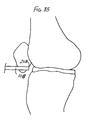
- FIG. 35 is a diagrammatic representation of a human knee joint similar to FIG. 31 , from the side.
- the instrument of the present invention is useful in delivering an orthopaedic implant, as defined above, to a damaged joint site in the body.
- the joint site may for example be the knee, where the instrument can be used to deliver an orthopaedic implant for use in approximating, repairing or regenerating a diseased or damaged meniscus.
- FIGS. 31-32 illustrates the use of one embodiment of the present invention in delivering an orthopaedic implant to an intra-articular site in the knee.
- the intra-articular site may be in other locations in the body, such as the temporomandibular joint, between vertebrae, or any site where there is fibrocartilage in need of approximation, repair or regeneration.
- the instrument of the present invention may also find utility in delivering an implant to damaged tissue sites other than the joints.
- “Damaged tissue site”, unless expressly limited in the claims, is intended to mean a tissue site that requires surgical repair, whether due to injury, degeneration or disease.
- the first embodiment of the instrument is designated 10 A
- the second embodiment is designated 10 B
- the third embodiment is designated 10 C
- the fourth embodiment 10 D is designated
- the fifth embodiment 10 E is designated
- the sixth embodiment 10 F the seventh embodiment 10 G and the eighth embodiment 10 H.
- All of these embodiments 10 A, 10 B, 10 C, 10 D, 10 E, 10 F, 10 G, 10 H share common components: they all include an elongate guide member 12 and an elongate reciprocable member 14 .
- the reciprocable member 14 is received in a telescoping manner within the elongate guide member.
- the elongate reciprocable member 14 A- 14 H in each of the embodiments 10 A- 10 H functions to move an orthopaedic implant, shown at 16 in FIGS. 1-2 , 5 - 6 , 9 - 11 , 14 - 15 , 22 - 25 and 32 - 34 , from a retracted position to an extended position.
- the distal end of the reciprocable member 14 A- 14 H and the orthopaedic implant 16 are between the proximal end 18 and distal end 20 of the elongate guide member 12 A- 12 H.
- the orthopaedic implant 16 can be of varying shapes and sizes.
- the orthopaedic implant 16 can comprise a generally rectangular sheet as shown in FIG. 2A , with a length shown at d 1 , a width shown at d 2 , a thickness shown at d 3 , and a diagonal dimension shown at d 4 .
- the orthopaedic implant 16 can have a pillow or pouch of additional material, such as shown at 17 in FIGS. 1-2B .
- This additional material can comprise, for example: extracellular matrix material; bioactive agents, biologically-derived agents, cells, a biological lubricant, a biocompatible synthetic or a biocompatible inorganic material, for example.
- Many such orthopaedic implants are flexible, particularly when hydrated.
- the implant 16 When the orthopaedic implant 16 has been delivered to the damaged joint site, the implant can be unrolled or unfolded to its full size, returning the implant to the original shape, such as the shape shown in FIG. 2A .
- the illustrated shapes of orthopaedic implants are provided as examples only; the present invention is not limited to any particular shape of orthopaedic implant unless expressly called for in the claims.
- orthopaedic implant will depend somewhat on its intended end use; for example, a typical orthopaedic implant for use in rotator cuff repair could have a larger surface area than an orthopaedic implant for use in meniscal repair, although the meniscal repair implant could in some instances have a greater thickness.
- the implant can fit within the interior of the hollow elongate guide member 12 A- 12 H.
- the elongate guide member 12 A of the first surgical instrument 10 A comprises a hollow tube open at both the proximal end 18 A and distal end 20 A.
- the interior surface 13 A of the elongate guide member 12 A has an inner transverse dimension shown at d 7 in FIGS. 4-4D .
- the length d 1 and width d 2 of the orthopaedic implant 16 can be greater than the maximum inner transverse dimension d 7 if the orthopaedic implant is in its natural shape ( FIG. 2A ), the implant can be deformed until the dimension d 5 or d 6 is less than the inner transverse dimension d 7 of the elongate guide member 12 A so that the implant can be received in the elongate guide member.
- the elongate guide member 12 A illustrated in FIGS. 1-2 and 4 - 4 D generally comprises a tube or cannula open at both proximal and distal ends 18 A, 20 A, with the outer surface and inner surface 13 A being circular in shape when viewed from either the proximal end 18 A or distal end 20 A.
- this shape is provided as an example only; variations in the shape of the elongate guide member are possible, and the invention should not be considered to be limited to a particular shape unless expressly set forth in the claims.
- the elongate guide member 12 A could have a slot 32 as shown in FIG. 4B .
- the elongate guide member 12 A could have an elliptical shape when viewed from the proximal end or distal end, as shown in FIGS. 4C and 4D , and could also have a slot 32 as shown in FIG. 4D .
- Other shapes can also be used, such as the shape illustrated in FIGS. 14-15 .
- the elongate guide member 12 A could also have other features, such as an actuator handle as described below with respect to the surgical instruments 10 F and 10 H.
- the illustrated elongate guide members 12 A- 12 H generally comprise integral structures, it should be understood that assemblies could be used as well.
- the elongate reciprocable member 14 B- 14 H includes an implant carrier portion 24 B and a pusher portion 26 B.
- the implant carrier portion 24 B, 24 C, 24 E and pusher portion 26 B, 26 C, 26 E can be integral, as in the surgical instruments 10 B, 10 C and 10 E of FIGS. 5-11 and 14 - 15 .
- the implant carrier portion 24 D, 24 F, 24 G, 24 H and pusher portion 26 D, 26 F, 26 G, 26 H can also be discrete elements as in the surgical instruments 10 D, 10 F, 10 G and 10 H, as shown in FIGS. 12-13 and 16 - 30 .
- the discrete implant carrier 24 F, 24 G, 24 H and pusher 26 F, 26 G, 26 H can be connected to form an assembly, as in the surgical instruments 10 F, 10 G and 10 H, as shown in FIGS. 16-30 , or could be separate components of the surgical instrument, as in the surgical instrument 10 D of FIGS. 12-13 .
- the reciprocable member of the surgical instrument need not include an implant carrier; in the first illustrated surgical instrument 10 A of FIGS. 1-4 , the reciprocable member 14 A is defined by a pusher 26 A element alone; there is no implant carrier in the first illustrated surgical instrument 10 A.
- the pusher 26 A of the reciprocable member 14 A comprises a shaft 28 A and an enlarged diameter head 30 A at the distal end of the shaft.
- the shaft 28 A has a length of about 6 inches and a diameter of about 12 mm; the length of the shaft 28 A is generally long enough so that the surgeon can grasp at least the distal end of the shaft both when the reciprocable member 14 A is in the retracted position ( FIG. 1 ) and the extended position ( FIG. 2 ); thus the shaft 28 A is longer than the elongate guide member 12 A.
- the head 30 A of the reciprocable member 14 A has an outer diameter shown at d 8 in FIG. 3 .
- the wall of the illustrated elongate guide member 12 A has a total thickness of about 1.5 mm.
- Typical arthroscopic portals have a length of about 8-12 mm.
- the surgical instrument 10 A can also be used in a minimally invasive procedure, such as a mini-arthrotomy, as well as in an open arthrotomy or other orthopaedic surgical procedure.
- the instruments could have larger sizes for use in these other procedures.
- the present invention is not limited to any particular dimension unless expressly called for in the claims.
- the surgeon would first place the distal end 20 A of the elongate guide member 12 A at the damaged joint site. This step may be performed arthroscopically if desired. The surgeon would then fold or roll the orthopaedic implant 16 so that the implant can be inserted into the proximal end 18 A of the elongate guide member 12 A. With the reciprocable member 14 A disassembled from the elongate guide member 12 A, the surgeon would then insert the orthopaedic implant 16 into the proximal end 18 A of the elongate guide member 12 A and then insert the head 30 of the reciprocable member 14 A into the proximal end 18 A of the elongate guide member 12 A.
- the reciprocable member 14 A and orthopaedic implant would then be in a retracted position, such as that shown in FIG. 1 .
- the surgeon would then push the reciprocable member 14 A through the elongate guide member 12 A toward the distal end 20 A, so that the head 30 A pushes the orthopaedic implant 16 in a distal direction until the orthopaedic implant 16 is pushed out the distal end 20 A of the elongate guide member 12 A and thereby delivered to the damaged joint site.
- the surgical instrument 10 A and orthopaedic implant 16 would be in the extended position illustrated in FIG. 2 .
- the surgeon can then pull the reciprocable member 14 A in a proximal direction and remove it from the elongate guide member 12 A, leaving the elongate guide member in place for use with other instruments if desired; alternatively, the surgeon can pull both the reciprocable member and the elongate guide member in a proximal direction to remove both components of the instrument from the surgical site.
- the inner surface 13 A of the elongate guide member 10 A is preferably smooth to enable the orthopaedic element to be slid along the inner surface 13 A easily and without damage.
- the elongate guide member 12 A and the reciprocable member 14 A can both be made of a surgical grade plastic, such as medical grade ABS, for example.
- the present invention is not limited to any particular material for any of the components of the surgical instrument.
- the orthopaedic implant 16 is delivered to the damaged joint site while protected from damage by the elongate guide member 12 A.
- the surgeon may unfold or unroll the implant to restore it to its original shape.
- the surgeon can then secure the implant in place at the damaged joint site.
- the surgeon may use the device disclosed in U.S. patent application Ser. No. 10/609,768 (now U.S. Pat. No. 7,473,259 issued Dec. 17, 2008), entitled “Implant Stabilizing Instrument, Kit and Method,” filed concurrently herewith by Andrew M. Jacobs, Carolyn K. Day, Rhonda B. Clarke, Herbert E. Schwartz, John W. Kemppainen, Prasanna Malaviya and Anthony D. Zannis, which is incorporated by reference herein in its entirety.
- the instrument, kit and method disclosed in that patent application may be used to move and stabilize the implant while securing the implant to the native tissue.
- the elongate guide member 12 B may be of the same construction and size as that of the first surgical instrument 10 A, and may be shaped as illustrated in FIGS. 4-4D .
- the second surgical instrument 10 B differs from the first surgical instrument 10 A primarily in the features and operation of the reciprocable member 14 B.
- the reciprocable member 14 B comprises a hollow tube and includes an implant carrier 24 B at its distal end and a pusher 26 B extending proximally from the implant carrier to the proximal end of the reciprocable member 14 B.
- the reciprocable member 14 B is an integral component: the implant carrier 24 B and pusher 26 B are integral parts of the elongate reciprocable member 14 B.
- the implant carrier portion 24 B of the elongate reciprocable member 14 B of the second instrument 10 B has a pair of spaced longitudinal slots 34 , 36 at its distal end, defining an integral arm 38 between the slots 34 , 36 .
- the orthopaedic implant 16 can be temporarily fixed to the distal end of the reciprocable member 14 B by wrapping the orthopaedic implant around the outer circumference of the elongate reciprocal member at the implant carrier 24 B. Part of the implant is inserted in each of the slots 34 , 36 so that part of the implant is in the interior of the reciprocable member beneath the arm 38 , thereby temporarily securing the implant to the implant carrier portion 24 B of the reciprocable member 14 B.
- the elongate reciprocable member 14 B may be made of any standard surgical grade material, such as a surgical grade plastic.
- An example of a suitable material is medical grade ABS.
- the elongate reciprocable member 14 B may have a wall thickness of about 1-2 mm, an inner diameter of 8 mm and an outer diameter of 10 mm.
- the slots 34 , 36 may have a length of about 25 mm and a width of about 2 mm, and the arm 38 may have a length of about 2 mm and a width of about 4 mm. It should be understood that this material and these dimensions are provided as examples only; the present invention is not limited to this material or dimension unless expressly set forth in the claims.
- the implant carrier 24 B provides a structure to which the orthopaedic implant 16 can be temporarily secured and moved from a point outside of the body to a joint site, and more particularly to a damaged joint site.
- Providing such an implant carrier is advantageous in protecting the implant as it is moved to the damaged joint site, particularly where the damaged joint site is in an intra-articular space.
- any force necessary to move the implant can be exerted on the implant carrier 24 B rather than on the orthopaedic implant itself.
- the implant carrier is in a retracted position within the elongate guide member as the distal end of the elongate guide member is moved to the damaged joint site, the orthopaedic implant is protected from damage as it is moved into the damaged joint site.
- Providing such an implant carrier also gives the surgeon some flexibility: the orthopaedic implant can be delivered to the damaged joint site in either a wet or dry condition.
- the surgeon would wrap the orthopaedic implant around the outer surface of the implant carrier portion 24 B of the reciprocable member 14 B and tuck a portion of the implant through the slots 34 , 36 and under the arm 38 .
- the remainder of the surgical procedure would be similar to that described above for the first illustrated instrument 10 A.
- FIG. 31 illustrates the second instrument 10 B with the distal end 20 B of the elongate guide member 12 B in position at the damaged joint site.
- the damaged joint site is the intra-articular space of the knee, shown generally at 39 .
- FIG. 32 illustrates the second instrument 10 B with the implant carrier 24 B in the extended position at the damaged joint site 39 .
- the surgeon may use standard surgical instruments, such as forceps, to remove the orthopaedic implant 16 from the implant carrier 24 B and place the implant at the desired position at the damaged joint site, such as along the site of a menisectomy.
- the second illustrated instrument can be used to deliver orthopaedic implants to other damaged joint sites as well.
- the present invention is not limited to any particular site unless expressly set forth in the claims.
- the implant carrier 24 B is movable along the elongate guide member 12 B in both a proximal-distal direction and a distal-proximal direction.
- the elongate guide member 12 B defines the path of travel of the implant carrier 24 B.
- the elongate guide member 12 B and the implant carrier 24 B are shaped to protect the orthopaedic implant from damage from tissue or other internal obstacles, which could otherwise tear, or damage the implant.
- the third illustrated surgical instrument 10 C shares features of both the first and second illustrated instruments 10 A, 10 B.
- the elongate guide member 12 C can be substantially the same as those described above for the first and second instruments 10 A, 10 B.
- the elongate reciprocable member 14 C of the third illustrated surgical instrument 10 C comprises an elongate rod pusher portion 26 C and an implant carrier portion 24 C.
- the implant carrier portion 24 C of the third illustrated instrument 10 C comprises a flexible enlarged portion of the distal end of the elongate reciprocable member 14 C.
- the flexibility of the implant carrier portion 24 C allows it to elastically deform to conform to the shape of the curved interior surface of the elongate guide member 12 C when in the retracted position as shown in FIG. 10 .
- the implant carrier portion 24 C has a maximum transverse dimension less than or equal to the inner diameter d 7 of the elongate guide member 12 C.
- the implant carrier portion 24 C springs back to its enlarged shape, as shown in FIG. 11 , where its maximum transverse dimension is that shown at d 9 in FIG. 11 .
- the orthopaedic implant also springs back to its original shape as shown in FIG. 11 , where its maximum transverse dimension is greater than the maximum transverse dimension d 7 of the inner surface of the elongate guide member 12 C.
- the third surgical instrument 10 C allows for delivery of an orthopaedic implant larger than the maximum transverse dimension of the elongate guide member 12 C to the damaged joint site.
- the implant carrier portion 24 C has a plurality of spaced, small through-holes, shown at 42 in FIG. 10 .
- the orthopaedic implant 16 can be temporarily secured to the implant carrier portion 24 C by suturing the implant to the implant carrier. Such sutures are shown at 44 in FIGS. 10-11 .
- any surgical grade material with elastic properties can be used for the implant carrier portion 24 C of the third surgical instrument 10 C.
- An example of a suitable material is shape-memory plastic.
- a commercially available flexible shape memory material such as the Nitinol alloy of nickel and titanium can also be used. However, it should be understood that this material is provided as an example only; the invention is not limited to use of any particular material unless expressly set forth in the claims.
- the implant carrier portion 24 C of the reciprocable member 14 C is integral with the pusher portion 26 C.
- these two portions could comprise discrete elements assembled to form the reciprocable member 14 C.
- the pusher portion 26 C of the reciprocable member 14 C comprises a solid elongate rod, similar to the pusher portion 26 A of the first illustrated instrument 10 A.
- the pusher portion 26 C of either embodiment could be a hollow tube as well.
- the third illustrated surgical instrument 10 C is similar to that described above for the first two illustrated surgical instruments 10 A, 10 B.
- the surgeon would suture the orthopaedic implant 16 to the implant carrier portion 24 C of the reciprocable member 12 C and then deliver the implant to the damaged joint site by pushing the pusher portion 26 C of the reciprocable member 12 C and implant through the elongate guide member 12 C.
- the implant carrier 24 B would spring into its expanded shape shown in FIG. 11 .
- the surgeon can use standard surgical instruments to cut the sutures 44 and move the orthopaedic implant from the implant carrier 24 C to the desired site at the joint.
- the fourth illustrated surgical instrument 10 D shares many features with those of the first three illustrated surgical instruments 10 A, 10 B, 10 C.
- the pusher portion 26 D of the reciprocable member 14 D is essentially the same as that described above for the first surgical instrument 10 A.
- the distal end 20 D of the elongate guide member 12 D of the fourth illustrated surgical instrument 10 D includes an annular shoulder 45 ; the remainder of the elongate guide member 12 D is essentially the same as those described above for the first three illustrated instruments 10 A, 10 B, 10 C.
- the surgical instrument 10 D includes a discrete implant carrier 24 D that is not connected to the pusher 26 D.
- the illustrated discrete implant carrier 24 D includes a cylindrical proximal portion 46 and integral opposing clip arms 48 , 50 extending axially from the cylindrical portion.
- the cylindrical portion 46 has an outer diameter slightly less than the inner diameter of the elongate guide member, and an axial length great enough to provide stability to the implant carrier 24 D within the elongate guide member 12 D.
- the annular shoulder 45 of the elongate guide member 12 D and the cylindrical portion 46 of the implant carrier 24 D cooperate to prevent the implant carrier 24 D from fully exiting from the distal end 20 D of the elongate guide member 12 D. In the fully extended position, only the opposing clip arms 48 , 50 of the implant carrier 24 D extend beyond the distal end 20 D of the elongate guide member 12 D.
- the discrete implant carrier 24 D of the fourth illustrated instrument 10 D may be made of any standard surgical grade material. It may be desirable for the clip arms 48 , 50 to be made of a flexible material such as spring stainless steel for example. However, the present invention is not limited to any particular material or property of material unless expressly set forth in the claims.
- the surgeon would place part of the orthopaedic implant between the two opposing clip arms 48 , 50 of the implant carrier 24 D and then place the combination of the implant carrier 24 D and orthopaedic implant 16 into the proximal end 18 D of the elongate guide member 12 D, with the implant and clip arms facing the distal end 20 D of the elongate guide member 12 D.
- the pusher 26 D is inserted into the proximal end 18 D of the elongate guide member 12 D so that the head 30 D of the pusher 26 D is nearest the cylindrical portion 46 of the implant carrier 24 D.
- the distal end 20 D of the elongate guide member 12 D is inserted at the damaged joint site, and the pusher 26 D is pushed in a distal direction to thereby push the insert carrier 24 D distally until the clip arms 48 , 50 and orthopaedic implant are in the extended position shown in FIG. 13 .
- the surgeon can then use standard surgical instruments such as forceps at the damaged joint site to remove the orthopaedic implant from between the clip arms 48 , 50 and place the implant at the desired site for permanent attachment to the native soft tissue.
- use of the fourth illustrated surgical instrument 10 D allows for delivery of an orthopaedic implant larger than the maximum transverse dimension of the elongate guide member 12 D to the damaged joint site. And as with the other illustrated surgical instruments 10 A- 10 C and 10 E- 10 H, the fourth illustrated surgical instrument 10 D protects the orthopaedic implant from damage from tissue or other internal obstacles as the implant is delivered from outside the body to the damaged joint site.
- the elongate guide member 12 E comprises a slide, open at the top.
- the slide has guide channels 52 , 54 along its side edges.
- the maximum transverse inner dimension d 7 of the slide is the transverse distance between these channels 52 , 54 .
- the reciprocable member 14 E of the fifth illustrated instrument 10 E comprises an integral implant carrier portion 24 E and pusher portion 26 E.
- the implant carrier portion 24 E comprises a covered box open on the distal side.
- the implant carrier portion 24 E has side edges 56 , 58 received and slidable within the guide channels 52 , 54 of the elongate guide member 12 E when the implant carrier is in the retracted position shown in FIG. 14 .
- the pusher portion 26 E comprises a thin flexible sheet with side edges received within the guide channels 52 , 54 of the elongate guide member 12 E.
- the elongate guide member 12 E of the fifth illustrated instrument 10 E can have other shapes.
- the shapes of the pusher portion 26 E and the implant carrier portion 24 E of the fifth illustrated instrument may be varied from those illustrated in FIGS. 14-15 to complement the shape of the elongate guide member 12 E.
- the orthopaedic implant can be folded or rolled and then placed in the implant carrier portion 24 E for delivery from outside of the body to the damaged joint site.
- the side edges 56 , 58 of the implant carrier portion 24 E can be inserted within the channels 52 , 54 at the proximal end 18 E of the elongate guide member outside the body.
- the surgeon can then push the implant carrier portion 24 E and implant along the length of the elongate guide member 12 E until the implant carrier portion 24 E is at the damaged joint site.
- the surgeon can then use standard surgical instruments to remove the implant from the implant carrier portion 24 E and secure the implant at the damaged joint site.
- use of the fifth illustrated surgical instrument 10 E allows for delivery of an orthopaedic implant larger than the maximum transverse dimension of the elongate guide member 12 E to the damaged joint site. And as with the other illustrated surgical instruments 10 A- 10 D and 10 F- 10 H, the fifth illustrated surgical instrument 10 E protects the orthopaedic implant from damage from tissue or other internal obstacles as the implant is delivered from outside the body to the damaged joint site.
- FIGS. 16-23 A sixth embodiment of the surgical instrument of the present invention is illustrated in FIGS. 16-23 .
- the elongate guide member 12 F includes a hollow tube portion 60 F and a handle portion 62 F at the proximal end 18 F of the elongate guide member 12 F.
- the handle portion 62 F has an enlarged diameter for the surgeon to hold, while the hollow tube portion 60 F has an outer diameter that allows for use in arthroscopic surgical procedures, mini-arthrotomies or open arthrotomies.
- the hollow tube portion 60 F has a J-shaped slot 64 F extending from the exterior to the interior surface.
- the J-shaped slot 64 F has two axially-oriented segments 66 F, 68 F joined at their distal ends by a transverse segment 70 F.
- the J-shaped slot 64 F receives a pin 72 F fixed to the reciprocable member 14 F of the sixth illustrated instrument 10 F.
- the reciprocable member 14 F of the sixth illustrated instrument 10 F comprises an assembly of four components. As best seen in FIGS. 18-19 , these four components include an elongate cylindrical shaft 74 F, an enlarged actuator 76 F connected to the proximal end of the elongate cylindrical shaft 74 F, a connector member 78 F connected to the elongate cylindrical shaft 74 F, and an implant carrier 24 F connected to the connector member 78 F.
- the elongate cylindrical shaft 74 F has an outside diameter that is slightly less than the inside diameter of the hollow tube portion 60 F of the elongate guide member 14 F to allow the elongate shaft 74 F to be easily moved in the proximal and distal directions 22 , 23 within the hollow tube portion 60 F.
- the illustrated shaft 74 F is cylindrical, it should be understood that the invention is not limited to complementary cylindrical shapes for the shaft 74 F and inner surface of the tube 60 F.
- the elongate shaft 74 F has a first radial bore 80 F about midway between the proximal and distal ends of the shaft 74 F; this radial bore 80 F receives the pin 72 F in an interference fit.
- the first radial bore 80 F extends from the outer surface of the shaft inward.
- the length of the pin 72 F is greater than the depth of the bore 80 F so that an end of the pin is exposed beyond the outer surface of the shaft 74 F.
- the length of the pin 72 F is great enough to extend into the J-slot 64 F of the tube portion 60 F of the elongate guide member 14 F.
- the pin 72 F travels along the long axial segment 66 F of the J-slot until the pin reaches the transverse segment 70 F.
- the shaft 74 F of the pusher 26 F By rotating the shaft 74 F of the pusher 26 F relative to the tube portion 60 F of the elongate guide member 12 F, the pin 72 F can be moved along the short transverse segment 70 F of the J-shaped slot 64 F until the pin 72 F reaches the short axial segment 68 F of the slot 64 F.
- the shaft 74 F can then be moved slightly in the proximal direction 22 relative to the tube 60 F to move the pin 72 F to the proximal end of the short axial segment 68 F of the slot 64 F.
- the sixth surgical instrument 10 F also includes a spring 82 F positioned between the enlarged actuator 76 F and the handle portion 62 F of the elongate guide member 14 F, urging these two components apart. As shown in FIGS. 18-19 , the proximal end of the spring 82 F is received in a complementary recess in the interior of the actuator 76 F and the distal end of the spring 82 F is received in a complementary recess in the interior of the handle portion 62 F of the elongate guide member 12 F.
- the spring surrounds a portion of the elongate shaft 74 F near the proximal end of the shaft. The proximal end of the shaft 74 F is fixed to the actuator 76 F.
- the spring 82 F urges the shaft 74 F and the pin 72 F in a proximal direction, until the pin 72 F is at the proximal end of the long axial segment 66 F of the slot 64 F as shown in FIGS. 16 and 18 , defining a retracted position of the reciprocable member 14 F.
- the pin 72 F is at the proximal end of the short axial segment 68 F of the J-shaped slot 64 F, the reciprocable member 14 F is in its extended position. Provision of the slot 64 F and pin 72 F allows the surgeon to lock the instrument in the extended position.
- the shaft portion 74 F of the reciprocable member 14 F includes a transverse bore 84 F near the distal end of the shaft and an axial bore 86 F extending in a proximal direction from the distal end face of the shaft 74 F.
- the transverse bore is threaded and extends diametrically through the shaft 74 F and intersects the longitudinal bore 86 F.
- the longitudinal bore 86 F of the shaft 74 F receives an axial proximal rod 88 F portion of the connector member 78 F.
- a set screw (not shown) may be inserted through a bore 90 F (see FIGS.
- the set screw is threaded into the bore 84 F until it contacts the axial proximal rod portion 88 F of the connector member 78 F.
- the set screw is short enough so that no part of the screw extends past the outer surface of the elongate shaft 74 F of the reciprocable member 14 F; thus, the set screw does not interfere with movement of the reciprocable member 14 F in the proximal and distal directions 22 , 23 .
- the connector member 78 F also includes a cylindrical body portion 92 F and a distal axial rod portion 94 F.
- the cylindrical body portion 92 F has an outer diameter that is slightly smaller than the inner diameter of the tube portion 60 F of the elongate guide member 14 F to allow the cylindrical body portion 92 F to move freely in the proximal and distal directions while providing stability to the distal end of the reciprocable member 14 F.
- the cylindrical body portion remains within the tube portion 60 F throughout the range of motion of the illustrated surgical instrument 10 F.
- the distal axial rod portion 94 F moves out the distal end of the tube portion 60 F when the reciprocable member 14 F is in the extended position shown in FIGS. 17 , 19 , 21 and 23 .
- the connector member 78 F has a reduced diameter and a spherical end portion 96 F.
- the spherical end portion 96 F of the distal axial rod portion 94 F of the connector member 78 F is connected to the implant carrier portion 24 F of the sixth illustrated surgical instrument 10 F.
- the implant carrier portion 24 F of the sixth instrument 10 F comprises a base 98 F and a plurality of arms 100 F.
- the base 98 F and arms 100 F are integral.
- the base 98 F has a spherical shape with an interior surface shaped to complement the spherical end portion 96 F of the connector member 78 F for mounting the implant carrier 24 F to the connector member 78 F.
- the arms 100 F of the implant carrier portion 24 F extend outwardly from the base 98 F. In the illustrated embodiment, there are four arms 100 F spaced evenly about the base 98 F, although fewer or more arms could be used. The arms 100 F have different shapes depending on the position of the arms relative to the tube portion 60 F of the elongate guide member 12 F. As shown in FIGS. 18 , 20 and 22 , the implant carrier portion 24 F has a retracted position between the proximal end 18 F and distal end 20 F of the elongate guide member 12 F. When in the retracted position, the arms 100 F extend in a generally longitudinal direction; the free ends 102 F of the arms 100 F are directed toward the distal end 20 F of the elongate guide member 12 F. When in the extended position, the arms 100 F extend outward from the base 98 F in a radial direction, as shown in FIGS. 17 , 19 , 21 and 23 .
- the base 98 F and arms 100 F are made of a flexible material with elastic properties, such as a commercially available shape memory metal alloy like Nitinol (nickel-titanium alloy) or a suitable surgical grade polymer with such properties, such as shape-memory plastic.
- the natural shape of the base 98 F and arms 100 F is that shown in FIGS. 17 , 19 , 21 and 23 , with the arms 100 F extending radially outward from the base 98 F.
- the arms 100 F extend in a generally longitudinal direction.
- the elastic properties of the implant carrier portion 24 F urge the arms 100 F radially outward to the radially-expanded shape shown in FIGS. 17 , 19 , 21 and 23 .
- the maximum transverse dimension of the implant carrier portion 24 F is less than the inner transverse dimension d 7 of the tube portion 60 F of the elongate guide member 12 F.
- the expanded transverse dimension d 9 of the implant carrier portion is substantially greater than the inner transverse dimension d 7 of the tube portion 60 F of the elongate guide member 12 F.
- the expanded transverse dimension d 9 of the implant carrier portion 24 F may be 20 mm; it should be understood that this dimension is provided as an example only, and the present invention is not limited to any particular value for the expanded transverse dimension d 9 unless expressly called for in the claims. It should also be understood that dimensions may be varied depending on the intended end use of the surgical instrument.
- an instrument with a larger expanded transverse dimension for instruments intended for use in the shoulder than in the knee, or for instruments intended for use in a mini-arthrotomy instead of in an arthroscopic procedure.
- the implant carrier portion 24 F of the sixth illustrated instrument 10 F is a discrete component, it may be desirable to provide different sizes of implant carriers in a surgical kit to accommodate different sizes of orthopaedic implants.
- the free ends 102 F of the implant carrier portion 24 F of the sixth illustrated surgical instrument 10 F include cut-outs or notches 104 F. These notches 104 F function in securing the orthopaedic implant to the arms 100 F of the implant carrier portion 24 F.
- the orthopaedic implant has barbs 105 at its periphery for securing the implant to soft tissue at the damaged joint site in the body, the barbs 105 can be received in the notches 104 F in a friction fit to temporarily secure the implant to the implant carrier portion.
- the notches 104 F could also serve to receive sutures.
- notches 104 F are provided as an example of a structure that could be used to temporarily secure the orthopaedic implant to the implant carrier.
- the arms 100 F could also or alternatively include, for example, holes to receive suture for temporarily securing the implant to the implant carrier.
- connection between the implant carrier portion 24 F and the connector member 78 F of the reciprocable member 14 F can be varied from that illustrated.
- the spherical end portion 96 F could be part of the implant carrier 24 F and the complementary hollow portion could be part of the connector member 78 F.
- the connector member 78 F can be made of a material that should withstand the stresses exerted on the connector member by the deformation of the implant carrier 24 F as it is moved between the retracted and extended positions.
- the connector member 78 F can be made of a surgical grade metal such as surgical grade stainless steel.
- the shaft 74 F can be made of the same or a different material since the shaft 74 F will be subjected to less stress in use.
- the shaft 74 F can be made of a surgical grade polymer such as medical grade acetal.
- the shaft 74 F and connector member 78 F can also comprise an integral structure if desired.
- the surgeon would push the enlarged actuator 76 F in a distal direction and rotate the actuator 76 F to move the pin 72 F along the J-shaped slot 64 F until the pin 72 F is at the proximal end of the short axial segment 68 F of the slot, thereby temporarily locking the implant carrier portion 24 F in the extended position shown in FIGS. 17 , 19 , 21 and 23 .
- the surgeon can then secure part of the orthopaedic implant to the arms 100 F of the implant carrier portion 24 F, such as by wrapping suture around the implant and arm or, if the implant includes structures such as barbs, by placing one barb 105 in each notch 104 F.
- the surgeon can push slightly on the actuator 76 F and twist the actuator 76 F to release the pin 72 F and allow the spring 82 F to urge the actuator 76 F away from the elongate guide member 12 F to thereby move the shaft 74 F in a proximal direction 22 .
- the implant carrier 24 F is pulled into the interior of the tube portion 60 F of the elongate guide member 12 F.
- the inner surface of the tube portion 60 F of the elongate guide member deforms the arms 100 F of the implant carrier, pushing the arms 100 F closer together so that the entire implant carrier 24 F can fit within the tube portion 60 F of the elongate guide member 12 F.
- the orthopaedic implant folds into a more compact shape to fit within the tube portion 60 F of the elongate guide member 12 F, as shown in FIG. 22 .
- the distal end 20 F of the elongate guide member 12 F is inserted at the damaged joint site, as shown for example in FIG. 33 .
- the surgeon can push on the actuator 76 F to move the shaft 74 F in a distal direction 23 until the implant carrier portion 24 F is outside of the confines of the tube portion 60 F of the elongate guide member 12 F.
- the elasticity or shape memory of the arms 100 F urges the arms 100 F to the extended position as shown in FIG. 34 , thereby expanding the orthopaedic implant at the damaged joint site.
- the surgeon can then use standard surgical instruments such as forceps at the damaged joint site to remove the orthopaedic implant from the arms 100 F of the implant carrier 24 F and place the implant at the desired site for permanent attachment to the native soft tissue.
- use of the sixth illustrated surgical instrument 10 F allows for delivery of an orthopaedic implant larger than the maximum transverse dimension of the elongate guide member 12 F to the damaged joint site. And as with the other illustrated surgical instruments 10 A- 10 E and 10 G- 10 H, the sixth illustrated surgical instrument 10 F protects the orthopaedic implant from damage from tissue or other internal obstacles as the implant is delivered from outside the body to the damaged joint site.
- each arm 100 G has a free proximal end 106 G, a flexion portion 108 G, a planar portion 110 G and a clip 112 G at the free distal end 102 G.
- the arms 100 G are shaped so that the free proximal end 106 G is on the outside of the base 98 G, the flexion portion 108 G of each arm 100 G fits through a slot 114 G in the base 98 G, and the planar portion 110 G and distal end portion 102 G are distal to the base 98 G.
- the arms 100 G may be made of a flexible, elastic material such as a shape memory alloy like Nitinol or a polymer material.
- the base 98 G can be made of another material that does not deform as readily, such as standard surgical grade stainless steel or a polymer for example.
- the base 98 G can be connected to the distal rod portion of the connector member 78 G through any standard connection mechanism, such as a snap fit or through a mechanical connector like a screw or nut and bolt.
- the arms 100 G of the implant carrier 24 G of the seventh illustrated surgical instrument 10 G may be made so that their natural shape is that shown in FIG. 25 , with the planar portions 110 G and free distal ends 102 G extending radially outward and with the free proximal ends 106 G extending in a generally longitudinal direction.
- the position and natural shape illustrated in FIG. 25 define the extended position and shape of the implant carrier 24 G.
- FIG. 24 illustrates the retracted position and deformed shape of the implant carrier 24 G. In the deformed, retracted position, the arms 100 G extend in a generally distal direction and fit within the inner diameter of the tube portion 60 G of the elongate guide member 12 G.
- the end clip portions 112 G of the arms 100 G of the implant carrier 24 G of the seventh illustrated surgical instrument 10 G are provided for temporary mounting of the orthopaedic implant 16 to the implant carrier 24 G.
- the end clip portions 112 G may be integral or discrete spring action clips that bear against portions of the implant to secure a part of the implant to each arm as illustrated in FIGS. 24-25 . Portions of the implant can be received between the end clip portion 112 G and the underlying planar portion 110 G of the arms 100 G.
- the remainder of the seventh illustrated surgical instrument may be the same as that described above for the sixth illustrated surgical instrument 10 F. It should however be understood that some of the features of the sixth illustrated surgical instrument 10 F are optional ones; for example, the spring 82 F need not be used.
- the seventh illustrated surgical instrument 10 G would be substantially the same as that described above for the sixth illustrated surgical instrument 10 F.
- the main distinction in use of the seventh illustrated surgical instrument would be in the manner of temporarily securing the orthopaedic implant to the implant carrier 24 G. With the seventh illustrated surgical instrument 10 G, part of the implant would be tucked beneath each clip portion 112 G of the implant carrier 24 G.
- FIGS. 26-30 at 10 H An eighth embodiment of a surgical instrument in accordance with the present invention is illustrated in FIGS. 26-30 at 10 H.
- the eighth illustrated surgical instrument shares many common features with the sixth and seventh illustrated instruments 10 F, 10 G as described above.
- the implant carrier 24 H of the eighth illustrated instrument 10 H has arms 100 H with end clips 112 H like those of the seventh instrument 10 G.
- the implant carrier portion 24 H and the distal rod 94 H of the connector member 78 H of the eighth illustrated surgical instrument 10 H are somewhat different from those of the sixth and seventh illustrated surgical instruments 10 F, 10 G.
- the distal end of the distal rod 94 H has flat parallel surfaces 120 H.
- the base 98 H of the implant carrier 24 H is integral with the arms 100 H, and comprises a pair of spaced parallel tabs 122 H (see FIGS. 27 and 30 ) that are placed against the flat parallel surfaces 120 H (see FIGS. 27 and 30 ) of the distal rod 94 H.
- the spaced parallel tabs 122 H are connected to the distal rod 94 H through screws, bolts, pins or the like extending through aligned holes in the tabs 122 H and flat surfaces 120 H.
- Use of the eighth illustrated surgical instrument 10 H is like that described above for use of the sixth and seventh illustrated surgical instruments 10 F, 10 G.
- the instrument of the present invention can also be used to deliver other types of implants to other damaged tissue sites in the body.
- the present invention could be used to deliver any type of tissue scaffold, patch or graft to any type of tissue site, and the illustrated embodiments may be modified if desired to allow for such use.
- the claims should not be construed as being limited to the delivery of orthopaedic implants to damaged joint sites.
Abstract
Description
Claims (31)
Priority Applications (1)
| Application Number | Priority Date | Filing Date | Title |
|---|---|---|---|
| US10/610,288 US7819880B2 (en) | 2003-06-30 | 2003-06-30 | Implant delivery instrument |
Applications Claiming Priority (1)
| Application Number | Priority Date | Filing Date | Title |
|---|---|---|---|
| US10/610,288 US7819880B2 (en) | 2003-06-30 | 2003-06-30 | Implant delivery instrument |
Publications (2)
| Publication Number | Publication Date |
|---|---|
| US20040267277A1 US20040267277A1 (en) | 2004-12-30 |
| US7819880B2 true US7819880B2 (en) | 2010-10-26 |
Family
ID=33541104
Family Applications (1)
| Application Number | Title | Priority Date | Filing Date |
|---|---|---|---|
| US10/610,288 Active 2026-04-06 US7819880B2 (en) | 2003-06-30 | 2003-06-30 | Implant delivery instrument |
Country Status (1)
| Country | Link |
|---|---|
| US (1) | US7819880B2 (en) |
Cited By (30)
| Publication number | Priority date | Publication date | Assignee | Title |
|---|---|---|---|---|
| US20110224702A1 (en) * | 2010-03-11 | 2011-09-15 | Craig Van Kampen | Tendon repair implant and method of arthroscopic implantation |
| US20130245707A1 (en) * | 2011-02-15 | 2013-09-19 | Charles L. Euteneuer | Anatomical location markers and methods of use in positioning sheet-like materials during surgery |
| US20130312761A1 (en) * | 2012-05-23 | 2013-11-28 | Nandhika Wijay | Acute and Permanent Occlusion Device, Delivery Catheter and Method |
| US8668718B2 (en) | 2009-06-04 | 2014-03-11 | Rotation Medical, Inc. | Methods and apparatus for fixing sheet-like materials to a target tissue |
| US8864780B2 (en) | 2011-02-15 | 2014-10-21 | Rotation Medical, Inc. | Methods and apparatus for delivering and positioning sheet-like materials |
| US9033201B2 (en) | 2011-02-15 | 2015-05-19 | Rotation Medical, Inc. | Methods and apparatus for fixing sheet-like materials to a target tissue |
| US9101460B2 (en) | 2009-01-08 | 2015-08-11 | Rotation Medical, Inc. | Implantable tendon protection systems and related kits and methods |
| US9107661B2 (en) | 2011-12-19 | 2015-08-18 | Rotation Medical, Inc. | Fasteners and fastener delivery devices for affixing sheet-like materials to bone or tissue |
| US9113977B2 (en) | 2011-02-15 | 2015-08-25 | Rotation Medical, Inc. | Guidewire having a distal fixation member for delivering and positioning sheet-like materials in surgery |
| US9125650B2 (en) | 2011-12-19 | 2015-09-08 | Rotation Medical, Inc. | Apparatus and method for forming pilot holes in bone and delivering fasteners therein for retaining an implant |
| US9179961B2 (en) | 2009-06-04 | 2015-11-10 | Rotation Medical, Inc. | Methods and apparatus for deploying sheet-like materials |
| US9179910B2 (en) | 2009-03-20 | 2015-11-10 | Rotation Medical, Inc. | Medical device delivery system and method |
| US9198751B2 (en) | 2011-02-15 | 2015-12-01 | Rotation Medical, Inc. | Methods and apparatus for delivering and positioning sheet-like materials in surgery |
| US9271726B2 (en) | 2011-12-19 | 2016-03-01 | Rotation Medical, Inc. | Fasteners and fastener delivery devices for affixing sheet-like materials to bone or tissue |
| US9314345B2 (en) | 2012-07-12 | 2016-04-19 | Vincent Traynelis | Spinal implant system and method |
| US9370356B2 (en) | 2011-12-19 | 2016-06-21 | Rotation Medical, Inc. | Fasteners and fastener delivery devices for affixing sheet-like materials to bone or tissue |
| US20170035474A1 (en) * | 2014-02-12 | 2017-02-09 | Wright Medical Technology, Inc. | Intramedullary implant, system, and method for inserting an implant into a bone |
| US20180092759A1 (en) * | 2009-03-27 | 2018-04-05 | Depuy Mitek, Llc | Methods and Devices for Delivering and Affixing Tissue Scaffolds |
| US10123796B2 (en) | 2014-11-04 | 2018-11-13 | Rotation Medical, Inc. | Medical implant delivery system and related methods |
| US10258459B2 (en) | 2014-05-09 | 2019-04-16 | Rotation Medical, Inc. | Medical implant delivery system and related methods |
| US10265156B2 (en) | 2015-06-15 | 2019-04-23 | Rotation Medical, Inc | Tendon repair implant and method of implantation |
| US10314689B2 (en) | 2015-12-31 | 2019-06-11 | Rotation Medical, Inc. | Medical implant delivery system and related methods |
| US20200107926A1 (en) * | 2018-10-05 | 2020-04-09 | Arthrex, Inc. | Method of biologic acromial resurfacing |
| US10758228B2 (en) | 2015-11-03 | 2020-09-01 | Rotation Medical, Inc. | Fastener delivery system and related methods |
| US10835368B2 (en) | 2017-12-07 | 2020-11-17 | Rotation Medical, Inc. | Medical implant delivery system and related methods |
| US10898228B2 (en) | 2015-05-06 | 2021-01-26 | Rotation Medical, Inc. | Medical implant delivery system and related methods |
| US11076851B2 (en) | 2014-11-04 | 2021-08-03 | Rotation Medical, Inc. | Medical implant delivery system and related methods |
| US11331499B2 (en) | 2016-07-28 | 2022-05-17 | University Of Utah Research Foundation | Medical device implant carrier for fragile medical implants |
| US11457916B2 (en) | 2014-11-04 | 2022-10-04 | Rotation Medical, Inc. | Medical implant delivery system and related methods |
| US11779371B1 (en) | 2022-10-28 | 2023-10-10 | Expand Medical Ltd. | Implant delivery device |
Families Citing this family (128)
| Publication number | Priority date | Publication date | Assignee | Title |
|---|---|---|---|---|
| DE602004025030D1 (en) * | 2003-06-27 | 2010-02-25 | Abs Corp | FUSSGELARTARTHROPLASTIE SYSTEM |
| US7819880B2 (en) | 2003-06-30 | 2010-10-26 | Depuy Products, Inc. | Implant delivery instrument |
| US7563266B2 (en) * | 2003-06-30 | 2009-07-21 | Depuy Products, Inc. | Slide and kit for delivering implants |
| US20050070919A1 (en) * | 2003-09-26 | 2005-03-31 | Lieberman Daniel M. | Device for guiding insertion of a medical device into the spinal epidural space and method therefor |
| US8673021B2 (en) * | 2003-11-26 | 2014-03-18 | Depuy Mitek, Llc | Arthroscopic tissue scaffold delivery device |
| CN1889892A (en) * | 2003-12-08 | 2007-01-03 | 辛迪思有限公司 | Surgical mallet |
| US7666188B2 (en) | 2003-12-16 | 2010-02-23 | Depuy Spine, Inc. | Methods and devices for spinal fixation element placement |
| US20050131407A1 (en) * | 2003-12-16 | 2005-06-16 | Sicvol Christopher W. | Flexible spinal fixation elements |
| US7527638B2 (en) | 2003-12-16 | 2009-05-05 | Depuy Spine, Inc. | Methods and devices for minimally invasive spinal fixation element placement |
| US7608092B1 (en) | 2004-02-20 | 2009-10-27 | Biomet Sports Medicince, LLC | Method and apparatus for performing meniscus repair |
| US7547318B2 (en) | 2004-03-19 | 2009-06-16 | Depuy Spine, Inc. | Spinal fixation element and methods |
| US8900236B2 (en) * | 2004-04-20 | 2014-12-02 | James Chappuis | Internal pedicle insulator implants assemblies and methods of use |
| US7338500B2 (en) * | 2004-04-20 | 2008-03-04 | Chappuis James L | Internal pedicle insulator apparatus and method of use |
| US8728132B2 (en) * | 2004-04-20 | 2014-05-20 | James L. Chappuis | Internal pedicle insulator apparatus and method of use |
| AU2005227409B2 (en) * | 2004-10-29 | 2012-01-19 | Depuy Products, Inc. | Implant system with sizing templates |
| AU2005227405B2 (en) * | 2004-10-29 | 2012-02-02 | Depuy Products, Inc. | Instruments, kit and method for suture management |
| US8303604B2 (en) | 2004-11-05 | 2012-11-06 | Biomet Sports Medicine, Llc | Soft tissue repair device and method |
| US8137382B2 (en) | 2004-11-05 | 2012-03-20 | Biomet Sports Medicine, Llc | Method and apparatus for coupling anatomical features |
| US7857830B2 (en) | 2006-02-03 | 2010-12-28 | Biomet Sports Medicine, Llc | Soft tissue repair and conduit device |
| US20060189993A1 (en) | 2004-11-09 | 2006-08-24 | Arthrotek, Inc. | Soft tissue conduit device |
| US7909851B2 (en) | 2006-02-03 | 2011-03-22 | Biomet Sports Medicine, Llc | Soft tissue repair device and associated methods |
| US7905904B2 (en) | 2006-02-03 | 2011-03-15 | Biomet Sports Medicine, Llc | Soft tissue repair device and associated methods |
| US7905903B2 (en) | 2006-02-03 | 2011-03-15 | Biomet Sports Medicine, Llc | Method for tissue fixation |
| US7749250B2 (en) | 2006-02-03 | 2010-07-06 | Biomet Sports Medicine, Llc | Soft tissue repair assembly and associated method |
| US9801708B2 (en) | 2004-11-05 | 2017-10-31 | Biomet Sports Medicine, Llc | Method and apparatus for coupling soft tissue to a bone |
| US8128658B2 (en) | 2004-11-05 | 2012-03-06 | Biomet Sports Medicine, Llc | Method and apparatus for coupling soft tissue to bone |
| US8298262B2 (en) | 2006-02-03 | 2012-10-30 | Biomet Sports Medicine, Llc | Method for tissue fixation |
| US8361113B2 (en) | 2006-02-03 | 2013-01-29 | Biomet Sports Medicine, Llc | Method and apparatus for coupling soft tissue to a bone |
| US7658751B2 (en) | 2006-09-29 | 2010-02-09 | Biomet Sports Medicine, Llc | Method for implanting soft tissue |
| US9017381B2 (en) | 2007-04-10 | 2015-04-28 | Biomet Sports Medicine, Llc | Adjustable knotless loops |
| US8118836B2 (en) | 2004-11-05 | 2012-02-21 | Biomet Sports Medicine, Llc | Method and apparatus for coupling soft tissue to a bone |
| US8088130B2 (en) | 2006-02-03 | 2012-01-03 | Biomet Sports Medicine, Llc | Method and apparatus for coupling soft tissue to a bone |
| US8840645B2 (en) | 2004-11-05 | 2014-09-23 | Biomet Sports Medicine, Llc | Method and apparatus for coupling soft tissue to a bone |
| US8998949B2 (en) | 2004-11-09 | 2015-04-07 | Biomet Sports Medicine, Llc | Soft tissue conduit device |
| US7914539B2 (en) | 2004-11-09 | 2011-03-29 | Biomet Sports Medicine, Llc | Tissue fixation device |
| US8034090B2 (en) | 2004-11-09 | 2011-10-11 | Biomet Sports Medicine, Llc | Tissue fixation device |
| US20070010816A1 (en) * | 2005-06-29 | 2007-01-11 | Wilkinson Trent R | Tool driver, coupler and associated method |
| US20070021838A1 (en) * | 2005-07-22 | 2007-01-25 | Dugas Jeffrey R | Site specific minimally invasive joint implants |
| US20080249533A1 (en) * | 2005-09-09 | 2008-10-09 | Biomedix, S.A. | Medical Device and Method For Controlling Obesity |
| US8921109B2 (en) | 2005-09-19 | 2014-12-30 | Histogenics Corporation | Cell-support matrix having narrowly defined uniformly vertically and non-randomly organized porosity and pore density and a method for preparation thereof |
| US8574235B2 (en) | 2006-02-03 | 2013-11-05 | Biomet Sports Medicine, Llc | Method for trochanteric reattachment |
| US11259792B2 (en) | 2006-02-03 | 2022-03-01 | Biomet Sports Medicine, Llc | Method and apparatus for coupling anatomical features |
| US8936621B2 (en) | 2006-02-03 | 2015-01-20 | Biomet Sports Medicine, Llc | Method and apparatus for forming a self-locking adjustable loop |
| US9271713B2 (en) | 2006-02-03 | 2016-03-01 | Biomet Sports Medicine, Llc | Method and apparatus for tensioning a suture |
| US8597327B2 (en) | 2006-02-03 | 2013-12-03 | Biomet Manufacturing, Llc | Method and apparatus for sternal closure |
| US8562645B2 (en) | 2006-09-29 | 2013-10-22 | Biomet Sports Medicine, Llc | Method and apparatus for forming a self-locking adjustable loop |
| US8652172B2 (en) | 2006-02-03 | 2014-02-18 | Biomet Sports Medicine, Llc | Flexible anchors for tissue fixation |
| US10517587B2 (en) | 2006-02-03 | 2019-12-31 | Biomet Sports Medicine, Llc | Method and apparatus for forming a self-locking adjustable loop |
| US9149267B2 (en) | 2006-02-03 | 2015-10-06 | Biomet Sports Medicine, Llc | Method and apparatus for coupling soft tissue to a bone |
| US8562647B2 (en) | 2006-09-29 | 2013-10-22 | Biomet Sports Medicine, Llc | Method and apparatus for securing soft tissue to bone |
| US8652171B2 (en) | 2006-02-03 | 2014-02-18 | Biomet Sports Medicine, Llc | Method and apparatus for soft tissue fixation |
| US8968364B2 (en) | 2006-02-03 | 2015-03-03 | Biomet Sports Medicine, Llc | Method and apparatus for fixation of an ACL graft |
| US8251998B2 (en) | 2006-08-16 | 2012-08-28 | Biomet Sports Medicine, Llc | Chondral defect repair |
| US7959650B2 (en) | 2006-09-29 | 2011-06-14 | Biomet Sports Medicine, Llc | Adjustable knotless loops |
| US8771352B2 (en) | 2011-05-17 | 2014-07-08 | Biomet Sports Medicine, Llc | Method and apparatus for tibial fixation of an ACL graft |
| US11311287B2 (en) | 2006-02-03 | 2022-04-26 | Biomet Sports Medicine, Llc | Method for tissue fixation |
| US9078644B2 (en) | 2006-09-29 | 2015-07-14 | Biomet Sports Medicine, Llc | Fracture fixation device |
| US8506597B2 (en) | 2011-10-25 | 2013-08-13 | Biomet Sports Medicine, Llc | Method and apparatus for interosseous membrane reconstruction |
| US8801783B2 (en) | 2006-09-29 | 2014-08-12 | Biomet Sports Medicine, Llc | Prosthetic ligament system for knee joint |
| US9538998B2 (en) | 2006-02-03 | 2017-01-10 | Biomet Sports Medicine, Llc | Method and apparatus for fracture fixation |
| US8888800B2 (en) | 2006-03-13 | 2014-11-18 | Pneumrx, Inc. | Lung volume reduction devices, methods, and systems |
| US9402633B2 (en) | 2006-03-13 | 2016-08-02 | Pneumrx, Inc. | Torque alleviating intra-airway lung volume reduction compressive implant structures |
| US8157837B2 (en) | 2006-03-13 | 2012-04-17 | Pneumrx, Inc. | Minimally invasive lung volume reduction device and method |
| US8303601B2 (en) | 2006-06-07 | 2012-11-06 | Stryker Spine | Collet-activated distraction wedge inserter |
| US8062303B2 (en) | 2006-08-16 | 2011-11-22 | K2M, Inc. | Apparatus and methods for inserting an implant |
| US7918857B2 (en) | 2006-09-26 | 2011-04-05 | Depuy Spine, Inc. | Minimally invasive bone anchor extensions |
| US8500818B2 (en) | 2006-09-29 | 2013-08-06 | Biomet Manufacturing, Llc | Knee prosthesis assembly with ligament link |
| US9918826B2 (en) | 2006-09-29 | 2018-03-20 | Biomet Sports Medicine, Llc | Scaffold for spring ligament repair |
| US11259794B2 (en) | 2006-09-29 | 2022-03-01 | Biomet Sports Medicine, Llc | Method for implanting soft tissue |
| US8672969B2 (en) | 2006-09-29 | 2014-03-18 | Biomet Sports Medicine, Llc | Fracture fixation device |
| US8118814B2 (en) * | 2007-02-14 | 2012-02-21 | Depuy Mitek Inc. | Implement for orientating a tool, particularly useful in surgical tools for harvesting and implanting bone plugs to repair damaged bone tissue |
| US20090012612A1 (en) * | 2007-04-10 | 2009-01-08 | David White | Devices and methods for push-delivery of implants |
| US20080255664A1 (en) * | 2007-04-10 | 2008-10-16 | Mdesign International | Percutaneously deliverable orthopedic joint device |
| US20080255501A1 (en) * | 2007-04-10 | 2008-10-16 | Michael Hogendijk | Percutaneous delivery and retrieval systems for shape-changing orthopedic joint devices |
| CA2695240C (en) * | 2007-08-13 | 2017-03-28 | Arch Day Design, Llc | Tissue positioning device |
| US8435241B2 (en) * | 2007-12-20 | 2013-05-07 | Depuy Products, Inc. | Keel punch impactor with connection device |
| US8449554B2 (en) | 2008-03-07 | 2013-05-28 | K2M, Inc. | Intervertebral implant and instrument with removable section |
| US7976578B2 (en) * | 2008-06-04 | 2011-07-12 | James Marvel | Buffer for a human joint and method of arthroscopically inserting |
| US8632605B2 (en) * | 2008-09-12 | 2014-01-21 | Pneumrx, Inc. | Elongated lung volume reduction devices, methods, and systems |
| US8382767B2 (en) * | 2008-10-31 | 2013-02-26 | K2M, Inc. | Implant insertion tool |
| US9277999B2 (en) * | 2009-02-27 | 2016-03-08 | University of Pittsburgh—of the Commonwealth System of Higher Education | Joint bioscaffolds |
| US8308814B2 (en) | 2009-03-27 | 2012-11-13 | Depuy Mitek, Inc. | Methods and devices for preparing and implanting tissue scaffolds |
| US8109935B2 (en) | 2009-05-15 | 2012-02-07 | Musculoskeletal Transplant Foundation | Implant inserter device |
| JP5809621B2 (en) | 2009-05-18 | 2015-11-11 | ヌームアールエックス・インコーポレーテッド | Implants for treating a patient's lungs |
| US20100305710A1 (en) | 2009-05-28 | 2010-12-02 | Biomet Manufacturing Corp. | Knee Prosthesis |
| US8911474B2 (en) | 2009-07-16 | 2014-12-16 | Howmedica Osteonics Corp. | Suture anchor implantation instrumentation system |
| US20110028794A1 (en) * | 2009-07-30 | 2011-02-03 | Ethicon Endo-Surgery, Inc. | Methods and devices for providing access into a body cavity |
| CA2713309C (en) | 2009-08-20 | 2013-07-02 | Howmedica Osteonics Corp. | Flexible acl instrumentation, kit and method |
| JP2013504389A (en) | 2009-09-11 | 2013-02-07 | アーティキュリンクス, インコーポレイテッド | Disc-shaped orthopedic device |
| EP2615974A4 (en) * | 2010-09-17 | 2017-10-04 | Histogenics Corporation | Method and apparatus for restoring articular cartilage |
| US9358122B2 (en) | 2011-01-07 | 2016-06-07 | K2M, Inc. | Interbody spacer |
| US8540721B2 (en) | 2011-04-04 | 2013-09-24 | Amicus Design Group, Llc | Adjustable apparatus and methods for inserting an implant |
| US9795398B2 (en) | 2011-04-13 | 2017-10-24 | Howmedica Osteonics Corp. | Flexible ACL instrumentation, kit and method |
| US9357991B2 (en) | 2011-11-03 | 2016-06-07 | Biomet Sports Medicine, Llc | Method and apparatus for stitching tendons |
| US9357992B2 (en) | 2011-11-10 | 2016-06-07 | Biomet Sports Medicine, Llc | Method for coupling soft tissue to a bone |
| US9370350B2 (en) | 2011-11-10 | 2016-06-21 | Biomet Sports Medicine, Llc | Apparatus for coupling soft tissue to a bone |
| US9381013B2 (en) | 2011-11-10 | 2016-07-05 | Biomet Sports Medicine, Llc | Method for coupling soft tissue to a bone |
| US9445803B2 (en) | 2011-11-23 | 2016-09-20 | Howmedica Osteonics Corp. | Filamentary suture anchor |
| US9259217B2 (en) | 2012-01-03 | 2016-02-16 | Biomet Manufacturing, Llc | Suture Button |
| US8821494B2 (en) | 2012-08-03 | 2014-09-02 | Howmedica Osteonics Corp. | Surgical instruments and methods of use |
| US9078740B2 (en) | 2013-01-21 | 2015-07-14 | Howmedica Osteonics Corp. | Instrumentation and method for positioning and securing a graft |
| US9402620B2 (en) | 2013-03-04 | 2016-08-02 | Howmedica Osteonics Corp. | Knotless filamentary fixation devices, assemblies and systems and methods of assembly and use |
| US9757119B2 (en) | 2013-03-08 | 2017-09-12 | Biomet Sports Medicine, Llc | Visual aid for identifying suture limbs arthroscopically |
| US9788826B2 (en) | 2013-03-11 | 2017-10-17 | Howmedica Osteonics Corp. | Filamentary fixation device and assembly and method of assembly, manufacture and use |
| US9463013B2 (en) | 2013-03-13 | 2016-10-11 | Stryker Corporation | Adjustable continuous filament structure and method of manufacture and use |
| US9918827B2 (en) | 2013-03-14 | 2018-03-20 | Biomet Sports Medicine, Llc | Scaffold for spring ligament repair |
| WO2014176270A1 (en) | 2013-04-22 | 2014-10-30 | Pivot Medical, Inc. | Method and apparatus for attaching tissue to bone |
| US9408721B2 (en) | 2013-07-03 | 2016-08-09 | Spine Innovation, Llc | Methods and apparatus for an insertion guide device |
| WO2015061790A2 (en) | 2013-10-25 | 2015-04-30 | Pneumrx, Inc. | Genetically-associated chronic obstructive pulmonary disease treatment |
| US10610211B2 (en) | 2013-12-12 | 2020-04-07 | Howmedica Osteonics Corp. | Filament engagement system and methods of use |
| US10136886B2 (en) | 2013-12-20 | 2018-11-27 | Biomet Sports Medicine, Llc | Knotless soft tissue devices and techniques |
| US9993268B2 (en) | 2014-05-28 | 2018-06-12 | James L. Chappuis | Internal pedicle insulator |
| US20150342610A1 (en) * | 2014-05-29 | 2015-12-03 | Pulmonx Corporation | Medical devices and methods for lung volume reduction |
| US9615822B2 (en) | 2014-05-30 | 2017-04-11 | Biomet Sports Medicine, Llc | Insertion tools and method for soft anchor |
| US9700291B2 (en) | 2014-06-03 | 2017-07-11 | Biomet Sports Medicine, Llc | Capsule retractor |
| CN105310773B (en) * | 2014-07-08 | 2017-09-22 | 苏州点合医疗科技有限公司 | A kind of Non-intermittent guided based on flank is automatically brought into operation formula vertebral column minimally invasive mechanical hand |
| US10390838B1 (en) | 2014-08-20 | 2019-08-27 | Pneumrx, Inc. | Tuned strength chronic obstructive pulmonary disease treatment |
| US10039543B2 (en) | 2014-08-22 | 2018-08-07 | Biomet Sports Medicine, Llc | Non-sliding soft anchor |
| US10702395B2 (en) * | 2014-10-01 | 2020-07-07 | Arthrosurface, Inc. | Microfracture apparatuses and methods |
| US9986992B2 (en) | 2014-10-28 | 2018-06-05 | Stryker Corporation | Suture anchor and associated methods of use |
| US10077420B2 (en) | 2014-12-02 | 2018-09-18 | Histogenics Corporation | Cell and tissue culture container |
| US10568616B2 (en) | 2014-12-17 | 2020-02-25 | Howmedica Osteonics Corp. | Instruments and methods of soft tissue fixation |
| US9955980B2 (en) | 2015-02-24 | 2018-05-01 | Biomet Sports Medicine, Llc | Anatomic soft tissue repair |
| US9974534B2 (en) | 2015-03-31 | 2018-05-22 | Biomet Sports Medicine, Llc | Suture anchor with soft anchor of electrospun fibers |
| US10722384B2 (en) * | 2017-03-01 | 2020-07-28 | Nordson Corporation | Medical material mixer and transfer apparatus and method for using the same |
| USD902405S1 (en) | 2018-02-22 | 2020-11-17 | Stryker Corporation | Self-punching bone anchor inserter |
| US11540920B2 (en) | 2019-10-17 | 2023-01-03 | Chap-Med, Inc. | Internal pedicle insulator |
| US20220211909A1 (en) * | 2021-01-04 | 2022-07-07 | Vivex Biologics Group, Inc. | Meniscus tear repair sling device |
Citations (66)
| Publication number | Priority date | Publication date | Assignee | Title |
|---|---|---|---|---|
| US2008380A (en) * | 1934-12-20 | 1935-07-16 | Bachmann Robert Alexander | Gynecological instrument |
| US3921632A (en) * | 1974-08-16 | 1975-11-25 | Frank M Bardani | Implant device |
| US4122556A (en) | 1977-03-23 | 1978-10-31 | Stanley Poler | Intra-ocular lens |
| US4349027A (en) | 1980-06-23 | 1982-09-14 | Difrancesco John G | Needle guide for implanting intra-ocular lens |
| US4681102A (en) * | 1985-09-11 | 1987-07-21 | Bartell Michael T | Apparatus and method for insertion of an intra-ocular lens |
| US4741330A (en) * | 1983-05-19 | 1988-05-03 | Hayhurst John O | Method and apparatus for anchoring and manipulating cartilage |
| US4750498A (en) | 1986-02-21 | 1988-06-14 | Coopervision, Inc. | Method and tool for inserting an intraocular lens |
| US4836202A (en) | 1986-11-03 | 1989-06-06 | Coopervision, Inc. | Instrument for manipulating compressible intraocular lenses |
| US4873976A (en) | 1984-02-28 | 1989-10-17 | Schreiber Saul N | Surgical fasteners and method |
| US4880429A (en) | 1987-07-20 | 1989-11-14 | Stone Kevin R | Prosthetic meniscus |
| US4981841A (en) | 1986-04-04 | 1991-01-01 | Allergan, Inc. | Methods and materials for use in corneal wound healing |
| US5007934A (en) | 1987-07-20 | 1991-04-16 | Regen Corporation | Prosthetic meniscus |
| US5036733A (en) | 1988-04-12 | 1991-08-06 | Tiholiz Ivan C | Co-aptive instruments with non-slip surfaces and method for their manufacture |
| US5108421A (en) | 1990-10-01 | 1992-04-28 | Quinton Instrument Company | Insertion assembly and method of inserting a vessel plug into the body of a patient |
| US5108438A (en) | 1989-03-02 | 1992-04-28 | Regen Corporation | Prosthetic intervertebral disc |
| US5129882A (en) | 1990-12-27 | 1992-07-14 | Novoste Corporation | Wound clotting device and method of using same |
| US5141507A (en) | 1991-12-06 | 1992-08-25 | Iolab Corporation | Soft intraocular lens |
| US5190552A (en) | 1992-02-04 | 1993-03-02 | Kelman Charles D | Slotted tube injector for an intraocular lens |
| US5290310A (en) | 1991-10-30 | 1994-03-01 | Howmedica, Inc. | Hemostatic implant introducer |
| US5306311A (en) | 1987-07-20 | 1994-04-26 | Regen Corporation | Prosthetic articular cartilage |
| US5320633A (en) | 1992-12-10 | 1994-06-14 | William C. Allen | Method and system for repairing a tear in the meniscus |
| US5320639A (en) | 1993-03-12 | 1994-06-14 | Meadox Medicals, Inc. | Vascular plug delivery system |
| US5374268A (en) | 1991-05-13 | 1994-12-20 | United States Surgical Corporation | Device and method for repairing torn tissue |
| US5569252A (en) | 1994-09-27 | 1996-10-29 | Justin; Daniel F. | Device for repairing a meniscal tear in a knee and method |
| US5571109A (en) | 1993-08-26 | 1996-11-05 | Man Ceramics Gmbh | System for the immobilization of vertebrae |
| US5653715A (en) | 1993-03-09 | 1997-08-05 | Chiron Vision Corporation | Apparatus for preparing an intraocular lens for insertion |
| US5681353A (en) | 1987-07-20 | 1997-10-28 | Regen Biologics, Inc. | Meniscal augmentation device |
| US5702418A (en) | 1995-09-12 | 1997-12-30 | Boston Scientific Corporation | Stent delivery system |
| US5702462A (en) | 1996-01-24 | 1997-12-30 | Oberlander; Michael | Method of meniscal repair |
| US5782830A (en) * | 1995-10-16 | 1998-07-21 | Sdgi Holdings, Inc. | Implant insertion device |
| US5873906A (en) | 1994-09-08 | 1999-02-23 | Gore Enterprise Holdings, Inc. | Procedures for introducing stents and stent-grafts |
| US5951587A (en) | 1997-10-09 | 1999-09-14 | Ethicon-Endo-Surgery, Inc. | Needle holder with suture filament grasping abilities |
| US5968052A (en) | 1996-11-27 | 1999-10-19 | Scimed Life Systems Inc. | Pull back stent delivery system with pistol grip retraction handle |
| US5971987A (en) | 1998-09-18 | 1999-10-26 | Ethicon, Inc. | Biocompatible absorbable polymer fastener and driver for use in surgical procedures |
| US5980524A (en) | 1997-06-02 | 1999-11-09 | Innovasive Devices, Inc. | Device for repairing a meniscal tear in a knee and method |
| US5984926A (en) | 1998-02-24 | 1999-11-16 | Jones; A. Alexander M. | Bone screw shimming and bone graft containment system and method |
| US5993475A (en) | 1998-04-22 | 1999-11-30 | Bristol-Myers Squibb Co. | Tissue repair device |
| US6042582A (en) | 1997-05-20 | 2000-03-28 | Ray; Charles D. | Instrumentation and method for facilitating insertion of spinal implant |
| US6056778A (en) | 1997-10-29 | 2000-05-02 | Arthrex, Inc. | Meniscal repair device |
| US6146385A (en) | 1997-02-11 | 2000-11-14 | Smith & Nephew, Inc. | Repairing cartilage |
| US6152935A (en) | 1996-12-11 | 2000-11-28 | Ethicon, Inc. | Meniscal repair device having integral spring member |
| US6176880B1 (en) | 1996-04-05 | 2001-01-23 | Depuy Orthopaedics, Inc. | Tissue graft construct for replacement of cartilaginous structures |
| US6273893B1 (en) | 1999-11-10 | 2001-08-14 | Ethicon, Inc. | Absorbable rivet/pin applier for use in surgical procedures |
| US6280449B1 (en) | 1997-10-24 | 2001-08-28 | Tekia, Inc. | Ophthalmologic insertor apparatus and methods of use |
| US20010023352A1 (en) | 1992-09-04 | 2001-09-20 | Gordon Norman S. | Suturing instruments and methods of use |
| US6293961B2 (en) | 1998-12-30 | 2001-09-25 | Ethicon, Inc. | Suture locking device |
| US6306156B1 (en) | 1997-11-20 | 2001-10-23 | Ron Clark | Meniscus repair anchor system |
| US6306159B1 (en) | 1998-12-23 | 2001-10-23 | Depuy Orthopaedics, Inc. | Meniscal repair device |
| US6319258B1 (en) | 1999-09-29 | 2001-11-20 | Ethicon, Inc. | Absorbable rivet/pin applier for use in surgical procedures |
| US6350274B1 (en) | 1992-05-11 | 2002-02-26 | Regen Biologics, Inc. | Soft tissue closure systems |
| US6491697B1 (en) | 1996-09-26 | 2002-12-10 | Bausch & Lomb | Method and apparatus for inserting a flexible membrane into an eye |
| US6572626B1 (en) * | 2000-10-19 | 2003-06-03 | Ethicon Endo-Surgery, Inc. | Surgical instrument having a fastener delivery mechanism |
| US6605093B1 (en) | 1997-10-24 | 2003-08-12 | Tekia, Inc. | Device and method for use with an ophthalmologic insertor apparatus |
| US6652561B1 (en) * | 2000-10-13 | 2003-11-25 | Opus Medical, Inc | Method and apparatus for attaching connective tissues to bone using a perforated suture anchoring device |
| US6770078B2 (en) | 2000-01-14 | 2004-08-03 | Peter M. Bonutti | Movable knee implant and methods therefor |
| US20040260305A1 (en) * | 2003-06-20 | 2004-12-23 | Bogomir Gorensek | Device for delivering an implant through an annular defect in an intervertebral disc |
| US20040267277A1 (en) | 2003-06-30 | 2004-12-30 | Zannis Anthony D. | Implant delivery instrument |
| US6929606B2 (en) | 2001-01-29 | 2005-08-16 | Depuy Spine, Inc. | Retractor and method for spinal pedicle screw placement |
| US20060095053A1 (en) | 2004-10-29 | 2006-05-04 | Zannis Anthony D | Method of delivering therapeutic implant |
| US20060095049A1 (en) | 2004-10-29 | 2006-05-04 | Zannis Anthony D | Implant system with sizing templates |
| US20060211953A1 (en) | 2004-10-29 | 2006-09-21 | Zannis Anthony D | Coordinate instrument set |
| US7160326B2 (en) | 2002-06-27 | 2007-01-09 | Depuy Products, Inc. | Method and apparatus for implantation of soft tissue implant |
| US7468041B2 (en) | 2003-06-26 | 2008-12-23 | Depuy Products, Inc. | Modular surgical instrument with reciprocable implement |
| US7473259B2 (en) | 2003-06-30 | 2009-01-06 | Depuy Products, Inc. | Implant stabilizing instrument, kit and method |
| US7559941B2 (en) | 2003-06-30 | 2009-07-14 | Depuy Products, Inc. | Instrument for delivery of implant |
| US7563266B2 (en) | 2003-06-30 | 2009-07-21 | Depuy Products, Inc. | Slide and kit for delivering implants |
Family Cites Families (1)
| Publication number | Priority date | Publication date | Assignee | Title |
|---|---|---|---|---|
| US6650274B1 (en) * | 2002-06-03 | 2003-11-18 | Raytheon Company | Radar imaging system and method |
-
2003
- 2003-06-30 US US10/610,288 patent/US7819880B2/en active Active
Patent Citations (77)
| Publication number | Priority date | Publication date | Assignee | Title |
|---|---|---|---|---|
| US2008380A (en) * | 1934-12-20 | 1935-07-16 | Bachmann Robert Alexander | Gynecological instrument |
| US3921632A (en) * | 1974-08-16 | 1975-11-25 | Frank M Bardani | Implant device |
| US4122556A (en) | 1977-03-23 | 1978-10-31 | Stanley Poler | Intra-ocular lens |
| US4349027A (en) | 1980-06-23 | 1982-09-14 | Difrancesco John G | Needle guide for implanting intra-ocular lens |
| US4741330A (en) * | 1983-05-19 | 1988-05-03 | Hayhurst John O | Method and apparatus for anchoring and manipulating cartilage |
| US4873976A (en) | 1984-02-28 | 1989-10-17 | Schreiber Saul N | Surgical fasteners and method |
| US4681102A (en) * | 1985-09-11 | 1987-07-21 | Bartell Michael T | Apparatus and method for insertion of an intra-ocular lens |
| US4750498A (en) | 1986-02-21 | 1988-06-14 | Coopervision, Inc. | Method and tool for inserting an intraocular lens |
| US4981841A (en) | 1986-04-04 | 1991-01-01 | Allergan, Inc. | Methods and materials for use in corneal wound healing |
| US4836202A (en) | 1986-11-03 | 1989-06-06 | Coopervision, Inc. | Instrument for manipulating compressible intraocular lenses |
| US4880429A (en) | 1987-07-20 | 1989-11-14 | Stone Kevin R | Prosthetic meniscus |
| US5007934A (en) | 1987-07-20 | 1991-04-16 | Regen Corporation | Prosthetic meniscus |
| US6042610A (en) | 1987-07-20 | 2000-03-28 | Regen Biologics, Inc. | Meniscal augmentation device |
| US5735903A (en) | 1987-07-20 | 1998-04-07 | Li; Shu-Tung | Meniscal augmentation device |
| US5306311A (en) | 1987-07-20 | 1994-04-26 | Regen Corporation | Prosthetic articular cartilage |
| US5681353A (en) | 1987-07-20 | 1997-10-28 | Regen Biologics, Inc. | Meniscal augmentation device |
| US5036733A (en) | 1988-04-12 | 1991-08-06 | Tiholiz Ivan C | Co-aptive instruments with non-slip surfaces and method for their manufacture |
| US5108438A (en) | 1989-03-02 | 1992-04-28 | Regen Corporation | Prosthetic intervertebral disc |
| US5108421A (en) | 1990-10-01 | 1992-04-28 | Quinton Instrument Company | Insertion assembly and method of inserting a vessel plug into the body of a patient |
| US5129882A (en) | 1990-12-27 | 1992-07-14 | Novoste Corporation | Wound clotting device and method of using same |
| US5374268A (en) | 1991-05-13 | 1994-12-20 | United States Surgical Corporation | Device and method for repairing torn tissue |
| US5290310A (en) | 1991-10-30 | 1994-03-01 | Howmedica, Inc. | Hemostatic implant introducer |
| US5141507A (en) | 1991-12-06 | 1992-08-25 | Iolab Corporation | Soft intraocular lens |
| US5190552A (en) | 1992-02-04 | 1993-03-02 | Kelman Charles D | Slotted tube injector for an intraocular lens |
| US6350274B1 (en) | 1992-05-11 | 2002-02-26 | Regen Biologics, Inc. | Soft tissue closure systems |
| US20010023352A1 (en) | 1992-09-04 | 2001-09-20 | Gordon Norman S. | Suturing instruments and methods of use |
| US5320633A (en) | 1992-12-10 | 1994-06-14 | William C. Allen | Method and system for repairing a tear in the meniscus |
| US5653715A (en) | 1993-03-09 | 1997-08-05 | Chiron Vision Corporation | Apparatus for preparing an intraocular lens for insertion |
| US5320639A (en) | 1993-03-12 | 1994-06-14 | Meadox Medicals, Inc. | Vascular plug delivery system |
| US5571109A (en) | 1993-08-26 | 1996-11-05 | Man Ceramics Gmbh | System for the immobilization of vertebrae |
| US6015429A (en) | 1994-09-08 | 2000-01-18 | Gore Enterprise Holdings, Inc. | Procedures for introducing stents and stent-grafts |
| US5873906A (en) | 1994-09-08 | 1999-02-23 | Gore Enterprise Holdings, Inc. | Procedures for introducing stents and stent-grafts |
| US5919225A (en) | 1994-09-08 | 1999-07-06 | Gore Enterprise Holdings, Inc. | Procedures for introducing stents and stent-grafts |
| US5569252A (en) | 1994-09-27 | 1996-10-29 | Justin; Daniel F. | Device for repairing a meniscal tear in a knee and method |
| US5702418A (en) | 1995-09-12 | 1997-12-30 | Boston Scientific Corporation | Stent delivery system |
| US5782830A (en) * | 1995-10-16 | 1998-07-21 | Sdgi Holdings, Inc. | Implant insertion device |
| US5702462A (en) | 1996-01-24 | 1997-12-30 | Oberlander; Michael | Method of meniscal repair |
| US6176880B1 (en) | 1996-04-05 | 2001-01-23 | Depuy Orthopaedics, Inc. | Tissue graft construct for replacement of cartilaginous structures |
| US6491697B1 (en) | 1996-09-26 | 2002-12-10 | Bausch & Lomb | Method and apparatus for inserting a flexible membrane into an eye |
| US6391051B2 (en) | 1996-11-27 | 2002-05-21 | Scimed Life Systems, Inc. | Pull back stent delivery system with pistol grip retraction handle |
| US5968052A (en) | 1996-11-27 | 1999-10-19 | Scimed Life Systems Inc. | Pull back stent delivery system with pistol grip retraction handle |
| US6238402B1 (en) | 1996-11-27 | 2001-05-29 | Boston Scientific Corporation | Pull back stent delivery system with pistol grip retraction handle |
| US6152935A (en) | 1996-12-11 | 2000-11-28 | Ethicon, Inc. | Meniscal repair device having integral spring member |
| US6156044A (en) | 1996-12-11 | 2000-12-05 | Ethicon, Inc. | Meniscal repair device |
| US6146385A (en) | 1997-02-11 | 2000-11-14 | Smith & Nephew, Inc. | Repairing cartilage |
| US6042582A (en) | 1997-05-20 | 2000-03-28 | Ray; Charles D. | Instrumentation and method for facilitating insertion of spinal implant |
| US5980524A (en) | 1997-06-02 | 1999-11-09 | Innovasive Devices, Inc. | Device for repairing a meniscal tear in a knee and method |
| US5951587A (en) | 1997-10-09 | 1999-09-14 | Ethicon-Endo-Surgery, Inc. | Needle holder with suture filament grasping abilities |
| US6605093B1 (en) | 1997-10-24 | 2003-08-12 | Tekia, Inc. | Device and method for use with an ophthalmologic insertor apparatus |
| US6280449B1 (en) | 1997-10-24 | 2001-08-28 | Tekia, Inc. | Ophthalmologic insertor apparatus and methods of use |
| US6056778A (en) | 1997-10-29 | 2000-05-02 | Arthrex, Inc. | Meniscal repair device |
| US6306156B1 (en) | 1997-11-20 | 2001-10-23 | Ron Clark | Meniscus repair anchor system |
| US5984926A (en) | 1998-02-24 | 1999-11-16 | Jones; A. Alexander M. | Bone screw shimming and bone graft containment system and method |
| US5993475A (en) | 1998-04-22 | 1999-11-30 | Bristol-Myers Squibb Co. | Tissue repair device |
| US5971987A (en) | 1998-09-18 | 1999-10-26 | Ethicon, Inc. | Biocompatible absorbable polymer fastener and driver for use in surgical procedures |
| US6306159B1 (en) | 1998-12-23 | 2001-10-23 | Depuy Orthopaedics, Inc. | Meniscal repair device |
| US6432123B2 (en) | 1998-12-30 | 2002-08-13 | Ethicon, Inc. | Suture locking device |
| US6319271B1 (en) | 1998-12-30 | 2001-11-20 | Depuy Orthopaedics, Inc. | Suture locking device |
| US6293961B2 (en) | 1998-12-30 | 2001-09-25 | Ethicon, Inc. | Suture locking device |
| US6319258B1 (en) | 1999-09-29 | 2001-11-20 | Ethicon, Inc. | Absorbable rivet/pin applier for use in surgical procedures |
| US6273893B1 (en) | 1999-11-10 | 2001-08-14 | Ethicon, Inc. | Absorbable rivet/pin applier for use in surgical procedures |
| US6770078B2 (en) | 2000-01-14 | 2004-08-03 | Peter M. Bonutti | Movable knee implant and methods therefor |
| US6652561B1 (en) * | 2000-10-13 | 2003-11-25 | Opus Medical, Inc | Method and apparatus for attaching connective tissues to bone using a perforated suture anchoring device |
| US6572626B1 (en) * | 2000-10-19 | 2003-06-03 | Ethicon Endo-Surgery, Inc. | Surgical instrument having a fastener delivery mechanism |
| US6929606B2 (en) | 2001-01-29 | 2005-08-16 | Depuy Spine, Inc. | Retractor and method for spinal pedicle screw placement |
| US7160326B2 (en) | 2002-06-27 | 2007-01-09 | Depuy Products, Inc. | Method and apparatus for implantation of soft tissue implant |
| US20040260305A1 (en) * | 2003-06-20 | 2004-12-23 | Bogomir Gorensek | Device for delivering an implant through an annular defect in an intervertebral disc |
| US7468041B2 (en) | 2003-06-26 | 2008-12-23 | Depuy Products, Inc. | Modular surgical instrument with reciprocable implement |
| US20040267277A1 (en) | 2003-06-30 | 2004-12-30 | Zannis Anthony D. | Implant delivery instrument |
| US7473259B2 (en) | 2003-06-30 | 2009-01-06 | Depuy Products, Inc. | Implant stabilizing instrument, kit and method |
| US7559941B2 (en) | 2003-06-30 | 2009-07-14 | Depuy Products, Inc. | Instrument for delivery of implant |
| US7563266B2 (en) | 2003-06-30 | 2009-07-21 | Depuy Products, Inc. | Slide and kit for delivering implants |
| US20060095053A1 (en) | 2004-10-29 | 2006-05-04 | Zannis Anthony D | Method of delivering therapeutic implant |
| US20060095049A1 (en) | 2004-10-29 | 2006-05-04 | Zannis Anthony D | Implant system with sizing templates |
| US20060095054A1 (en) | 2004-10-29 | 2006-05-04 | Zannis Anthony D | Instruments, kit and method for suture management |
| US20060095048A1 (en) | 2004-10-29 | 2006-05-04 | Zannis Anthony D | Method of repairing soft tissue using sizing templates |
| US20060211953A1 (en) | 2004-10-29 | 2006-09-21 | Zannis Anthony D | Coordinate instrument set |
Non-Patent Citations (2)
| Title |
|---|
| O'Connor's Textbook of Arthroscopic Surgery, 2nd ed., 1992, Chapter 19. |
| Rodeo, "Arthroscopic Meniscal Repair With Use of Outside-In Technique", Instr. Course Lect., 2000, 49, pp. 195-206. |
Cited By (89)
| Publication number | Priority date | Publication date | Assignee | Title |
|---|---|---|---|---|
| US9101460B2 (en) | 2009-01-08 | 2015-08-11 | Rotation Medical, Inc. | Implantable tendon protection systems and related kits and methods |
| US11116623B2 (en) | 2009-01-08 | 2021-09-14 | Rotation Medical, Inc. | Implantable tendon protection systems and related kits and methods |
| US10413397B2 (en) | 2009-01-08 | 2019-09-17 | Rotation Medical, Inc. | Implantable tendon protection systems and related kits and methods |
| US11413133B2 (en) | 2009-01-08 | 2022-08-16 | Rotation Medical, Inc. | Implantable tendon protection systems and related kits and methods |
| US10226325B2 (en) | 2009-03-20 | 2019-03-12 | Rotation Medical, Inc. | Medical device delivery system and method |
| US10806565B2 (en) | 2009-03-20 | 2020-10-20 | Rotation Medical, Inc. | Medical device delivery system and method |
| US9179910B2 (en) | 2009-03-20 | 2015-11-10 | Rotation Medical, Inc. | Medical device delivery system and method |
| US20180092759A1 (en) * | 2009-03-27 | 2018-04-05 | Depuy Mitek, Llc | Methods and Devices for Delivering and Affixing Tissue Scaffolds |
| US10821005B2 (en) * | 2009-03-27 | 2020-11-03 | DePuy Synthes Products, Inc. | Methods and devices for delivering and affixing tissue scaffolds |
| US11413082B2 (en) | 2009-06-04 | 2022-08-16 | Rotation Medical, Inc. | Methods and apparatus for deploying sheet-like materials |
| US10881441B2 (en) | 2009-06-04 | 2021-01-05 | Rotation Medical, Inc. | Methods and apparatus for deploying sheet-like materials |
| US10426464B2 (en) | 2009-06-04 | 2019-10-01 | Rotation Medical, Inc. | Methods and apparatus for fixing sheet-like materials to a target tissue |
| US9095337B2 (en) | 2009-06-04 | 2015-08-04 | Rotation Medical, Inc. | Methods and apparatus for delivering staples to a target issue |
| US10085785B2 (en) | 2009-06-04 | 2018-10-02 | Rotation Medical, Inc. | Methods and apparatus for deploying sheet-like materials |
| US11723706B2 (en) | 2009-06-04 | 2023-08-15 | Rotation Medical, Inc. | Methods and apparatus for deploying sheet-like materials |
| US10568622B2 (en) | 2009-06-04 | 2020-02-25 | Rotation Medical, Inc. | Methods and apparatus for delivering staples to a target tissue |
| US11793510B2 (en) | 2009-06-04 | 2023-10-24 | Rotation Medical, Inc. | Methods and apparatus for delivering staples to a target tissue |
| US9179961B2 (en) | 2009-06-04 | 2015-11-10 | Rotation Medical, Inc. | Methods and apparatus for deploying sheet-like materials |
| US9931119B2 (en) | 2009-06-04 | 2018-04-03 | Rotation Medical, Inc. | Methods and apparatus having bowstring-like staple delivery to a target tissue |
| US10653415B2 (en) | 2009-06-04 | 2020-05-19 | Rotation Medical, Inc. | Methods and apparatus having bowstring-like staple delivery to a target tissue |
| US9027819B2 (en) | 2009-06-04 | 2015-05-12 | Rotation Medical, Inc. | Methods and apparatus having bowstring-like staple delivery to a target tissue |
| US9675346B2 (en) | 2009-06-04 | 2017-06-13 | Rotation Medical, Inc. | Methods and apparatus for fixing sheet-like materials to a target tissue |
| US8840642B2 (en) | 2009-06-04 | 2014-09-23 | Rotation Medical, Inc. | Methods and apparatus for fixing sheet-like materials to a target tissue |
| US8821537B2 (en) | 2009-06-04 | 2014-09-02 | Rotation Medical, Inc. | Methods and apparatus for fixing sheet-like materials to a target tissue |
| US8668718B2 (en) | 2009-06-04 | 2014-03-11 | Rotation Medical, Inc. | Methods and apparatus for fixing sheet-like materials to a target tissue |
| US8821536B2 (en) | 2009-06-04 | 2014-09-02 | Rotation Medical, Inc. | Methods and apparatus for delivering staples to a target tissue |
| US8763878B2 (en) | 2009-06-04 | 2014-07-01 | Rotation Medical, Inc. | Methods and apparatus having bowstring-like staple delivery to a target tissue |
| US11051808B2 (en) | 2009-06-04 | 2021-07-06 | Rotation Medical, Inc. | Methods and apparatus for fixing sheet-like materials to a target tissue |
| US9198750B2 (en) * | 2010-03-11 | 2015-12-01 | Rotation Medical, Inc. | Tendon repair implant and method of arthroscopic implantation |
| US11717393B2 (en) | 2010-03-11 | 2023-08-08 | Rotation Medical, Inc. | Tendon repair implant and method of arthroscopic implantation |
| US9393104B2 (en) | 2010-03-11 | 2016-07-19 | Rotation Medical, Inc. | Tendon repair implant and method of arthroscopic implantation |
| US10864072B2 (en) | 2010-03-11 | 2020-12-15 | Rotation Medical, Inc. | Tendon repair implant and method of arthroscopic implantation |
| US10123866B2 (en) | 2010-03-11 | 2018-11-13 | Rotation Medical, Inc. | Tendon repair implant and method of arthroscopic implantation |
| US20110224702A1 (en) * | 2010-03-11 | 2011-09-15 | Craig Van Kampen | Tendon repair implant and method of arthroscopic implantation |
| US9393103B2 (en) | 2010-03-11 | 2016-07-19 | Rotation Medical, Inc. | Tendon repair implant and method of arthroscopic implantation |
| US10105210B2 (en) | 2010-03-11 | 2018-10-23 | Rotation Medical, Inc. | Tendon repair implant and method of arthroscopic implantation |
| US9204940B2 (en) * | 2011-02-15 | 2015-12-08 | Rotation Medical, Inc. | Anatomical location markers and methods of use in positioning sheet-like materials during surgery |
| US9743970B2 (en) | 2011-02-15 | 2017-08-29 | Rotation Medical, Inc. | Anatomical location markers and methods of use in positioning sheet-like materials during surgery |
| US9198751B2 (en) | 2011-02-15 | 2015-12-01 | Rotation Medical, Inc. | Methods and apparatus for delivering and positioning sheet-like materials in surgery |
| US9113977B2 (en) | 2011-02-15 | 2015-08-25 | Rotation Medical, Inc. | Guidewire having a distal fixation member for delivering and positioning sheet-like materials in surgery |
| US9993247B2 (en) | 2011-02-15 | 2018-06-12 | Rotation Medical, Inc. | Apparatus for fixing sheet-like materials to a target tissue |
| US10449031B2 (en) | 2011-02-15 | 2019-10-22 | Rotation Medical, Inc. | Methods and apparatus for delivering and positioning sheet-like materials |
| US9005224B2 (en) | 2011-02-15 | 2015-04-14 | Rotation Medical, Inc. | Methods and apparatus for delivering and positioning sheet-like materials |
| US8864780B2 (en) | 2011-02-15 | 2014-10-21 | Rotation Medical, Inc. | Methods and apparatus for delivering and positioning sheet-like materials |
| US9314331B2 (en) | 2011-02-15 | 2016-04-19 | Rotation Medical, Inc. | Methods and apparatus for delivering and positioning sheet-like materials in surgery |
| US9033201B2 (en) | 2011-02-15 | 2015-05-19 | Rotation Medical, Inc. | Methods and apparatus for fixing sheet-like materials to a target tissue |
| US9314314B2 (en) | 2011-02-15 | 2016-04-19 | Rotation Medical, Inc. | Anatomical location markers and methods of use in positioning sheet-like materials during surgery |
| US10195016B2 (en) | 2011-02-15 | 2019-02-05 | Rotation Medical, Inc. | Methods and apparatus for delivering and positioning sheet-like materials in surgery |
| US20130245707A1 (en) * | 2011-02-15 | 2013-09-19 | Charles L. Euteneuer | Anatomical location markers and methods of use in positioning sheet-like materials during surgery |
| US10245138B2 (en) | 2011-02-15 | 2019-04-02 | Rotation Medical, Inc. | Methods and apparatus for delivering and positioning sheet-like materials in surgery |
| US10105211B2 (en) | 2011-12-19 | 2018-10-23 | Rotation Medical, Inc. | Apparatus and method for forming pilot holes in bone and delivering fasteners therein for retaining an implant |
| US9125650B2 (en) | 2011-12-19 | 2015-09-08 | Rotation Medical, Inc. | Apparatus and method for forming pilot holes in bone and delivering fasteners therein for retaining an implant |
| US9247978B2 (en) | 2011-12-19 | 2016-02-02 | Rotation Medical, Inc. | Apparatus and method for forming pilot holes in bone and delivering fasteners therein for retaining an implant |
| US9271726B2 (en) | 2011-12-19 | 2016-03-01 | Rotation Medical, Inc. | Fasteners and fastener delivery devices for affixing sheet-like materials to bone or tissue |
| US9370356B2 (en) | 2011-12-19 | 2016-06-21 | Rotation Medical, Inc. | Fasteners and fastener delivery devices for affixing sheet-like materials to bone or tissue |
| US10058414B2 (en) | 2011-12-19 | 2018-08-28 | Rotation Medical, Inc. | Apparatus and method for forming pilot holes in bone and delivering fasteners therein for retaining an implant |
| US9955968B2 (en) | 2011-12-19 | 2018-05-01 | Rotation Medical, Inc. | Fasteners and fastener delivery devices for affixing sheet-like materials to bone or tissue |
| US11020111B2 (en) | 2011-12-19 | 2021-06-01 | Rotation Medical, Inc. | Fasteners and fastener delivery devices for affixing sheet-like materials to bone or tissue |
| US9855037B2 (en) | 2011-12-19 | 2018-01-02 | Rotation Medical, Inc. | Fasteners and fastener delivery devices for affixing sheet-like materials to bone or tissue |
| US10912640B2 (en) | 2011-12-19 | 2021-02-09 | Rotation Medical, Inc. | Apparatus and method for forming pilot holes in bone and delivering fasteners therein for retaining an implant |
| US9414841B2 (en) | 2011-12-19 | 2016-08-16 | Rotation Medical, Inc. | Fasteners and fastener delivery devices for affixing sheet-like materials to bone or tissue |
| US9107661B2 (en) | 2011-12-19 | 2015-08-18 | Rotation Medical, Inc. | Fasteners and fastener delivery devices for affixing sheet-like materials to bone or tissue |
| US9566063B2 (en) | 2011-12-19 | 2017-02-14 | Rotation Medical, Inc. | Fasteners and fastener delivery devices for affixing sheet-like materials to bone or tissue |
| US11051932B2 (en) | 2011-12-29 | 2021-07-06 | Rotation Medical, Inc. | Methods and apparatus for delivering and positioning sheet-like materials in surgery |
| US10952783B2 (en) | 2011-12-29 | 2021-03-23 | Rotation Medical, Inc. | Guidewire having a distal fixation member for delivering and positioning sheet-like materials in surgery |
| US9592148B2 (en) * | 2012-05-23 | 2017-03-14 | Nandhika Wijay | Acute and permanent occlusion device, delivery catheter and method |
| US20130312761A1 (en) * | 2012-05-23 | 2013-11-28 | Nandhika Wijay | Acute and Permanent Occlusion Device, Delivery Catheter and Method |
| US9314345B2 (en) | 2012-07-12 | 2016-04-19 | Vincent Traynelis | Spinal implant system and method |
| US20170035474A1 (en) * | 2014-02-12 | 2017-02-09 | Wright Medical Technology, Inc. | Intramedullary implant, system, and method for inserting an implant into a bone |
| US10258459B2 (en) | 2014-05-09 | 2019-04-16 | Rotation Medical, Inc. | Medical implant delivery system and related methods |
| US11331180B2 (en) | 2014-05-09 | 2022-05-17 | Rotation Medical, Inc. | Medical implant delivery system and related methods |
| US11806010B2 (en) | 2014-11-04 | 2023-11-07 | Rotation Medical, Inc. | Medical implant delivery system and related methods |
| US10675019B2 (en) | 2014-11-04 | 2020-06-09 | Rotation Medical, Inc. | Medical implant delivery system and related methods |
| US10123796B2 (en) | 2014-11-04 | 2018-11-13 | Rotation Medical, Inc. | Medical implant delivery system and related methods |
| US11076851B2 (en) | 2014-11-04 | 2021-08-03 | Rotation Medical, Inc. | Medical implant delivery system and related methods |
| US11457916B2 (en) | 2014-11-04 | 2022-10-04 | Rotation Medical, Inc. | Medical implant delivery system and related methods |
| US10898228B2 (en) | 2015-05-06 | 2021-01-26 | Rotation Medical, Inc. | Medical implant delivery system and related methods |
| US11510702B2 (en) | 2015-05-06 | 2022-11-29 | Rotation Medical, Inc. | Medical implant delivery system and related methods |
| US10888415B2 (en) | 2015-06-15 | 2021-01-12 | Rotation Medical, Inc. | Tendon repair implant and method of implantation |
| US11607305B2 (en) | 2015-06-15 | 2023-03-21 | Rotation Medical, Inc. | Tendon repair implant and method of implantation |
| US10265156B2 (en) | 2015-06-15 | 2019-04-23 | Rotation Medical, Inc | Tendon repair implant and method of implantation |
| US10758228B2 (en) | 2015-11-03 | 2020-09-01 | Rotation Medical, Inc. | Fastener delivery system and related methods |
| US10874503B2 (en) | 2015-12-31 | 2020-12-29 | Rotation Medical, Inc. | Medical implant delivery system and related methods |
| US10314689B2 (en) | 2015-12-31 | 2019-06-11 | Rotation Medical, Inc. | Medical implant delivery system and related methods |
| US11331499B2 (en) | 2016-07-28 | 2022-05-17 | University Of Utah Research Foundation | Medical device implant carrier for fragile medical implants |
| US10987210B2 (en) | 2017-12-07 | 2021-04-27 | Rotation Medical, Inc. | Medical implant delivery system and related methods |
| US10835368B2 (en) | 2017-12-07 | 2020-11-17 | Rotation Medical, Inc. | Medical implant delivery system and related methods |
| US20200107926A1 (en) * | 2018-10-05 | 2020-04-09 | Arthrex, Inc. | Method of biologic acromial resurfacing |
| US11779371B1 (en) | 2022-10-28 | 2023-10-10 | Expand Medical Ltd. | Implant delivery device |
Also Published As
| Publication number | Publication date |
|---|---|
| US20040267277A1 (en) | 2004-12-30 |
Similar Documents
| Publication | Publication Date | Title |
|---|---|---|
| US7819880B2 (en) | Implant delivery instrument | |
| US7473259B2 (en) | Implant stabilizing instrument, kit and method | |
| US8597352B2 (en) | Articular cartilage fixation device and method | |
| US7563266B2 (en) | Slide and kit for delivering implants | |
| US7559941B2 (en) | Instrument for delivery of implant | |
| US9486307B2 (en) | Flexible tibial sheath | |
| US6482210B1 (en) | Soft tissue/ligament to bone fixation device with inserter | |
| EP1378202B1 (en) | Suture anchor | |
| US7785332B2 (en) | Method of delivering therapeutic implant | |
| US20070162127A1 (en) | Instruments and techniques for delivering non-rigid implant members in surgical procedures | |
| US20040230194A1 (en) | Device and method for attaching soft tissue to bone | |
| US20200345348A1 (en) | Fastener delivery system and related methods | |
| JP6265444B2 (en) | Medical device used for transplantation to the patient's hip joint | |
| US20210361409A1 (en) | Device, system, and method for delivery of a tissue fixation device | |
| JP2020037025A (en) | Medical device for use in implantation of hip joint of patient | |
| US20240023953A1 (en) | Prosthesis supported tissue repair system and method |
Legal Events
| Date | Code | Title | Description |
|---|---|---|---|
| AS | Assignment |
Owner name: DEPUY PRODUCTS, INC., INDIANA Free format text: ASSIGNMENT OF ASSIGNORS INTEREST;ASSIGNORS:ZANNIS, ANTHONY D.;CAMINO, THOMAS S.;KEMPPAINEN, JOHN W.;AND OTHERS;REEL/FRAME:014586/0990;SIGNING DATES FROM 20031002 TO 20031013 Owner name: DEPUY PRODUCTS, INC., INDIANA Free format text: ASSIGNMENT OF ASSIGNORS INTEREST;ASSIGNORS:ZANNIS, ANTHONY D.;CAMINO, THOMAS S.;KEMPPAINEN, JOHN W.;AND OTHERS;SIGNING DATES FROM 20031002 TO 20031013;REEL/FRAME:014586/0990 |
|
| STCF | Information on status: patent grant |
Free format text: PATENTED CASE |
|
| FPAY | Fee payment |
Year of fee payment: 4 |
|
| AS | Assignment |
Owner name: DEPUY SYNTHES PRODUCTS, LLC, MASSACHUSETTS Free format text: CHANGE OF NAME;ASSIGNOR:HAND INNOVATIONS LLC;REEL/FRAME:032998/0644 Effective date: 20121231 Owner name: HAND INNOVATIONS LLC, FLORIDA Free format text: ASSIGNMENT OF ASSIGNORS INTEREST;ASSIGNOR:DEPUY SPINE, LLC;REEL/FRAME:032949/0887 Effective date: 20121230 Owner name: DEPUY SPINE, LLC, MASSACHUSETTS Free format text: ASSIGNMENT OF ASSIGNORS INTEREST;ASSIGNOR:DEPUY PRODUCTS, INC.;REEL/FRAME:032949/0620 Effective date: 20121230 |
|
| MAFP | Maintenance fee payment |
Free format text: PAYMENT OF MAINTENANCE FEE, 8TH YEAR, LARGE ENTITY (ORIGINAL EVENT CODE: M1552) Year of fee payment: 8 |
|
| MAFP | Maintenance fee payment |
Free format text: PAYMENT OF MAINTENANCE FEE, 12TH YEAR, LARGE ENTITY (ORIGINAL EVENT CODE: M1553); ENTITY STATUS OF PATENT OWNER: LARGE ENTITY Year of fee payment: 12 |