US7833181B2 - Adjustable ergonomic brace - Google Patents
Adjustable ergonomic brace Download PDFInfo
- Publication number
- US7833181B2 US7833181B2 US12/465,083 US46508309A US7833181B2 US 7833181 B2 US7833181 B2 US 7833181B2 US 46508309 A US46508309 A US 46508309A US 7833181 B2 US7833181 B2 US 7833181B2
- Authority
- US
- United States
- Prior art keywords
- stop
- hinge
- center axis
- strut
- locking member
- Prior art date
- Legal status (The legal status is an assumption and is not a legal conclusion. Google has not performed a legal analysis and makes no representation as to the accuracy of the status listed.)
- Expired - Fee Related
Links
Images


Classifications
-
- A—HUMAN NECESSITIES
- A61—MEDICAL OR VETERINARY SCIENCE; HYGIENE
- A61F—FILTERS IMPLANTABLE INTO BLOOD VESSELS; PROSTHESES; DEVICES PROVIDING PATENCY TO, OR PREVENTING COLLAPSING OF, TUBULAR STRUCTURES OF THE BODY, e.g. STENTS; ORTHOPAEDIC, NURSING OR CONTRACEPTIVE DEVICES; FOMENTATION; TREATMENT OR PROTECTION OF EYES OR EARS; BANDAGES, DRESSINGS OR ABSORBENT PADS; FIRST-AID KITS
- A61F5/00—Orthopaedic methods or devices for non-surgical treatment of bones or joints; Nursing devices; Anti-rape devices
- A61F5/01—Orthopaedic devices, e.g. splints, casts or braces
- A61F5/0102—Orthopaedic devices, e.g. splints, casts or braces specially adapted for correcting deformities of the limbs or for supporting them; Ortheses, e.g. with articulations
- A61F5/0123—Orthopaedic devices, e.g. splints, casts or braces specially adapted for correcting deformities of the limbs or for supporting them; Ortheses, e.g. with articulations for the knees
- A61F5/0125—Orthopaedic devices, e.g. splints, casts or braces specially adapted for correcting deformities of the limbs or for supporting them; Ortheses, e.g. with articulations for the knees the device articulating around a single pivot-point
-
- A—HUMAN NECESSITIES
- A61—MEDICAL OR VETERINARY SCIENCE; HYGIENE
- A61F—FILTERS IMPLANTABLE INTO BLOOD VESSELS; PROSTHESES; DEVICES PROVIDING PATENCY TO, OR PREVENTING COLLAPSING OF, TUBULAR STRUCTURES OF THE BODY, e.g. STENTS; ORTHOPAEDIC, NURSING OR CONTRACEPTIVE DEVICES; FOMENTATION; TREATMENT OR PROTECTION OF EYES OR EARS; BANDAGES, DRESSINGS OR ABSORBENT PADS; FIRST-AID KITS
- A61F5/00—Orthopaedic methods or devices for non-surgical treatment of bones or joints; Nursing devices; Anti-rape devices
- A61F5/01—Orthopaedic devices, e.g. splints, casts or braces
- A61F5/0102—Orthopaedic devices, e.g. splints, casts or braces specially adapted for correcting deformities of the limbs or for supporting them; Ortheses, e.g. with articulations
- A61F2005/0132—Additional features of the articulation
- A61F2005/0165—Additional features of the articulation with limits of movement
- A61F2005/0167—Additional features of the articulation with limits of movement adjustable
-
- Y—GENERAL TAGGING OF NEW TECHNOLOGICAL DEVELOPMENTS; GENERAL TAGGING OF CROSS-SECTIONAL TECHNOLOGIES SPANNING OVER SEVERAL SECTIONS OF THE IPC; TECHNICAL SUBJECTS COVERED BY FORMER USPC CROSS-REFERENCE ART COLLECTIONS [XRACs] AND DIGESTS
- Y10—TECHNICAL SUBJECTS COVERED BY FORMER USPC
- Y10T—TECHNICAL SUBJECTS COVERED BY FORMER US CLASSIFICATION
- Y10T24/00—Buckles, buttons, clasps, etc.
- Y10T24/44—Clasp, clip, support-clamp, or required component thereof
- Y10T24/44573—Clasp, clip, support-clamp, or required component thereof including track or way guided and retained gripping member
-
- Y—GENERAL TAGGING OF NEW TECHNOLOGICAL DEVELOPMENTS; GENERAL TAGGING OF CROSS-SECTIONAL TECHNOLOGIES SPANNING OVER SEVERAL SECTIONS OF THE IPC; TECHNICAL SUBJECTS COVERED BY FORMER USPC CROSS-REFERENCE ART COLLECTIONS [XRACs] AND DIGESTS
- Y10—TECHNICAL SUBJECTS COVERED BY FORMER USPC
- Y10T—TECHNICAL SUBJECTS COVERED BY FORMER US CLASSIFICATION
- Y10T24/00—Buckles, buttons, clasps, etc.
- Y10T24/44—Clasp, clip, support-clamp, or required component thereof
- Y10T24/44641—Clasp, clip, support-clamp, or required component thereof having gripping member formed from, biased by, or mounted on resilient member
- Y10T24/44744—Clasp, clip, support-clamp, or required component thereof having gripping member formed from, biased by, or mounted on resilient member with position locking-means for engaging faces
-
- Y—GENERAL TAGGING OF NEW TECHNOLOGICAL DEVELOPMENTS; GENERAL TAGGING OF CROSS-SECTIONAL TECHNOLOGIES SPANNING OVER SEVERAL SECTIONS OF THE IPC; TECHNICAL SUBJECTS COVERED BY FORMER USPC CROSS-REFERENCE ART COLLECTIONS [XRACs] AND DIGESTS
- Y10—TECHNICAL SUBJECTS COVERED BY FORMER USPC
- Y10T—TECHNICAL SUBJECTS COVERED BY FORMER US CLASSIFICATION
- Y10T24/00—Buckles, buttons, clasps, etc.
- Y10T24/46—Pin or separate essential cooperating device therefor
- Y10T24/4604—Pin or separate essential cooperating device therefor having distinct guiding, holding, or protecting means for penetrated portion
- Y10T24/4634—Pin or separate essential cooperating device therefor having distinct guiding, holding, or protecting means for penetrated portion including relatively movable guiding, holding, or protecting components or surfaces
-
- Y—GENERAL TAGGING OF NEW TECHNOLOGICAL DEVELOPMENTS; GENERAL TAGGING OF CROSS-SECTIONAL TECHNOLOGIES SPANNING OVER SEVERAL SECTIONS OF THE IPC; TECHNICAL SUBJECTS COVERED BY FORMER USPC CROSS-REFERENCE ART COLLECTIONS [XRACs] AND DIGESTS
- Y10—TECHNICAL SUBJECTS COVERED BY FORMER USPC
- Y10T—TECHNICAL SUBJECTS COVERED BY FORMER US CLASSIFICATION
- Y10T403/00—Joints and connections
- Y10T403/32—Articulated members
- Y10T403/32254—Lockable at fixed position
- Y10T403/32262—At selected angle
- Y10T403/32319—At selected angle including pivot stud
- Y10T403/32327—At selected angle including pivot stud including radially spaced detent or latch component
-
- Y—GENERAL TAGGING OF NEW TECHNOLOGICAL DEVELOPMENTS; GENERAL TAGGING OF CROSS-SECTIONAL TECHNOLOGIES SPANNING OVER SEVERAL SECTIONS OF THE IPC; TECHNICAL SUBJECTS COVERED BY FORMER USPC CROSS-REFERENCE ART COLLECTIONS [XRACs] AND DIGESTS
- Y10—TECHNICAL SUBJECTS COVERED BY FORMER USPC
- Y10T—TECHNICAL SUBJECTS COVERED BY FORMER US CLASSIFICATION
- Y10T403/00—Joints and connections
- Y10T403/32—Articulated members
- Y10T403/32254—Lockable at fixed position
- Y10T403/32262—At selected angle
- Y10T403/32319—At selected angle including pivot stud
- Y10T403/32377—Radially spaced arcuate slot engages fastener
-
- Y—GENERAL TAGGING OF NEW TECHNOLOGICAL DEVELOPMENTS; GENERAL TAGGING OF CROSS-SECTIONAL TECHNOLOGIES SPANNING OVER SEVERAL SECTIONS OF THE IPC; TECHNICAL SUBJECTS COVERED BY FORMER USPC CROSS-REFERENCE ART COLLECTIONS [XRACs] AND DIGESTS
- Y10—TECHNICAL SUBJECTS COVERED BY FORMER USPC
- Y10T—TECHNICAL SUBJECTS COVERED BY FORMER US CLASSIFICATION
- Y10T403/00—Joints and connections
- Y10T403/32—Articulated members
- Y10T403/32606—Pivoted
Definitions
- This invention related to ergonomic knee braces.
- the brace include arrangements for limiting the movement of the lower leg relative to the upper leg both as to bending the knee or flexion, and as to extension of the lower leg relative to the upper leg.
- Various knee brace arrangements have been proposed, and these have included upper struts for extending along the thigh, and lower struts for extending along the lower leg or calf. These are normally provided both on the inside or medial side of the leg and also on the outer or lateral side of the leg; and the medial and lateral struts are normally padded, and provided with straps to hold them in place. Pivoting arrangements are provided for coupling the upper and lower struts, and stops are provided for limiting both extension and flexion of the knee.
- objects of the invention include providing a knee brace which is compact, easy to use, which has many points of adjustment and is otherwise ergonomically configured.
- the adjustments should be simple and natural so that there is no need to resort to collateral written instructions.
- the knee brace stop construction operates at the periphery of the pivot arrangements so that the number of stop increments is maximized for the size of the pivot discs.
- the stops may be operated by simple inward pressure on a push button associated with the flexion stop or the extension stop, to release the stop, followed by rotation of the stop to virtually any desired angle, and then followed by release of the push button to permit locking of the stop in the new angular position.
- the stop adjustments may be easily made while the brace is mounted on the leg; and the mode of accomplishing stop adjustments is substantially self evident, with the shifting of the stops resulting in the natural or expected angular change in flexion or extension stops.
- the pivoting assembly interconnecting the upper and lower struts includes, for both extension and flexion, at least one generally circular or arcuate catch plate with stop recesses facing or opening inward toward the center of the assembly, and a movable stop member pivoted at the center of the assembly and having an outwardly biased locking member for selectively engaging one of the stop recesses, and with the locking member attached to a release button which extends radially outward to the periphery of the pivot assembly.
- the pivoting assembly may include an outer cover or closure plate and an inner cover or closure plate; an arcuately configured array of locking steps; a movable stop member pivoted at the center of the assembly and having an outwardly biased locking member for selectively engaging at least one of the locking steps; and with the locking member attached to a release button which is located radially outward at the periphery of the pivot assembly.
- Additional features may include the provision of angular indicia on the outer surface of the outer one of said cover or closure plates and the implementation of the movable stop assembly by an outer, radially extending flat support member adjacent the indicia, preferably with a window through which the angular indicia may be seen. Further, the movable stop assembly may extend over the edge of one of said plates into the space between the two cover plates to cooperate with the locking steps. This construction contributes to the relatively thin overall configuration of the pivoting assembly, which may be only about one-half inch or about 1.3 cm thick. Also, to provide adequate strength and compactness, the brace and it components are preferably made of high strength material such as steel, titanium, zinc alloys, or other high strength metals or high strength plastic.
- each of the stop assemblies includes a pin which seats in corresponding recesses in each of the two catch plates, to provide a balanced locking configuration for resisting forces applied between the struts to limit flexion or extension.
- the inner and outer cover plates may also have complementary recesses to more positively secure the stops at the selected angular position.
- one strut extends from the knee pivot assembly up the upper leg or thigh, and the other strut extends from the pivot assembly down the lower leg.
- the pivot stop assembly is mounted on the end of a first one of these struts, and the second strut has stop surfaces on its end adjacent the stop assembly which engage the flexion and extension stops.
- the catch plates as described above are mounted on opposite sides of this second strut, with the locking member of the movable stop assembly engaging locking steps on both of the two catch plates, so that a balanced positive stopping force is transmitted to the second strut when the stop surfaces on the end of the second strut engage the flexion stop or the extension stop.
- knee brace may include the following:
- FIG. 1 is a perspective view of a knee brace assembly illustrating the principles of the invention
- FIG. 2 is a plan view of one of the two knee braces included in the knee brace assembly of FIG. 1 ;
- FIG. 3 is a side view of the knee brace of FIG. 2 ;
- FIG. 4 is an enlarged plan view of a knee brace pivot and motion limiting assembly, illustrating the principles of the invention
- FIG. 5 is an enlarged perspective view of the pivot assembly
- FIG. 6 is an exploded view of the knee brace assembly illustrating the principles of the invention.
- FIG. 7 is an enlarged view of the central pivot and stop assembly of the knee brace of FIGS. 1-6 , with the front cover removed;
- FIG. 8 is an exploded view of the two movable stops and their associated adjustment buttons, and indication support members
- FIGS. 9-12 show various stop adjustment configurations for the knee brace
- FIG. 13 is an exploded perspective view of an alternative embodiment knee brace assembly
- FIG. 13 a is a cross-sectional view showing the interaction of the detent and the adjustment hole of the strut extension.
- FIG. 14 is an exploded perspective view of the hinge assembly for the knee brace shown in FIG. 13 .
- FIG. 1 shows a leg brace 12 for the knee, including two struts extending up and down the leg from a central pivot assembly 14 .
- strut 16 Extending along the upper leg is a strut 16 , and extending down the lower leg from the pivot assembly 14 is a lower strut 18 .
- These struts are sometimes referenced as femoral struts (as extending along the femur or upper leg bone) and tibial struts (extending along the tibia, or the principal lower leg bone).
- a pivot assembly on the other side of the knee is also provided with struts extending up and down the leg, but these are not visible in FIG. 1 .
- a series of straps 22 on the upper leg, and straps 24 on the lower leg are a series of straps 22 on the upper leg, and straps 24 on the lower leg.
- Suitable padding 26 is provided on the upper leg, and the struts are normally secured to the padding 26 by appropriate VELCRO® or hook and loop type material.
- Similar padding 28 underlies the strut 18 and straps 24 .
- the straps 22 extend through the loops 38 to hold the entire assembly together under active usage conditions.
- the present invention is directed primarily to the pivot stop assemblies which interconnect the struts.
- FIG. 1 The showing of FIG. 1 is of the outside of the left leg. On the inside of the left leg is a similar assembly, to that shown in FIG. 1 , with two struts and a central pivot assembly. The two units are similar and both are held to the leg by the straps 22 and 24 . Most of the parts are common to the inner and outer assemblies, but with the struts and the cover plates being mirror images of one another.
- the two struts 16 and 18 are pivoted relative to one another about center rivet 56 ; and strut 18 has two stop surfaces 32 and 34 .
- Adjustable stops are mounted to the hinge pivot assembly 14 on strut 16 and the adjustable stops engage stop surfaces 32 and 34 to limit pivoting of the knee in both the extension and the flexion directions.
- FIG. 2 of the drawings shows the assembly 12 and the pivot assembly 14 with the straps 22 and 24 , and the padding 26 and 28 removed. Visible in FIG. 2 are the strap coupling members 36 which are secured to the struts, and the strap receiving openings 38 .
- FIG. 3 is a side view of the assembly of FIG. 2 .
- the pivot assembly 14 will be described in greater detail hereinbelow.
- FIGS. 4 and 5 of the drawings are plan and perspective views, respectively of the pivot assembly 14 which interconnects the struts 16 and 18 .
- FIG. 4 it includes the extension stop assembly 42 and the flexion stop assembly 44 .
- Visible on the cover plate 46 are degree indicia which may be read through the openings 48 and 50 on the stop assemblies 42 and 44 , respectively.
- the push buttons 52 and 54 are depressed and the stop assemblies are rotated to the desired angular settings.
- the outermost surfaces of push buttons 52 and 54 are preferably knurled, ribbed or textured for non-slip engagement.
- the stops may be coated with a frictional coating.
- the flexion stop 44 when it is set to 120° the lower leg may be fully bent toward the upper leg. When the flexion stop is set to “lock”, then the lower leg is fully extended, and is blocked from any bending. If both stops 42 and 44 are set to 60° for example, the knee is held at 60° from fully open, and is restrained from movement in either direction.
- the support members for the stops are both pivoted about the center 56 of the pivot assembly 14 , with the reference number 56 representing the head of a rivet extending through the assembly.
- one of the two struts 18 has the two stop surfaces 32 and 34 on its end, and is pivoted, with opening 62 receiving rivet 56 which extends through the entire assembly.
- the flat parts 64 and 66 are spacers and also serve the function of washers in facilitating rotation of the overlying parts. They may be formed of plastic such as nylon.
- the catch plates 68 and 70 have a series of inwardly opening recesses which receive outwardly biased locking pins as described below.
- the inner cover plate 72 and the outer cover plate 74 may also be provided with inwardly directed recesses, matching those in the catch plates 68 and 70 . This provides supplemental restraint for the locking pins shown in detail in later figures of the drawings.
- FIG. 7 is an enlarged view of the central mechanism with one of the cover plates removed.
- the stop assembly 44 has a locking pin 82 which moves inward with the push button 54 to change settings, but is spring biased outward to engage one of the recesses 84 .
- the locking pin 86 associated with push button 52 locks the stop 42 by engagement with a selected one of the catch plate recesses 84 .
- FIG. 8 is an enlarged showing of the physical stop members 92 and 94 which engage the stop surfaces 32 and 34 as shown in FIG. 6 .
- Two small pairs of coil springs 96 and 98 serve to bias the push buttons 52 and 54 , and the associated locking pins 86 and 82 outward, into engagement with the catch plate 68 (see FIG. 7 ) and the other catch plate 70 (see FIG. 6 ).
- the physical stops 92 and 94 may be formed of a high strength zinc alloy referenced as ZA-28, or other high strength material.
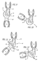
- FIGS. 9 through 12 shows various adjustments of the stops, and the resultant permitted positions of the struts 16 and 18 . More specifically, FIG. 9 shows the extension stop 42 and the flexion stop 44 in their positions for full range of motion, with the extension stop 42 at 0° and the extension stop 44 at 120° (see FIG. 4 ). In FIG. 9 the struts (and the leg) are fully extended; while in FIG. 10 , the struts and the leg are bent to their extreme flexed position, with the two stops in the same positions for both FIG. 9 and FIG. 10 .
- FIG. 11 is a similar pair of drawings with the extension stop at about 45° and the flexion stop at about 75° in both figures.
- the struts are extended as far as possible with this setting of stops 42 and 44 ; and in FIG. 12 the struts (and leg) are bent as far as permitted with this setting of the stops 42 and 44 .
- An alternative embodiment of the stop mechanism may include a physical stop having a radially extending slot for receiving a locking pin associated with a push button; and a wire spring biasing the push button and locking pin radially outward relative to the stop support members.
- push buttons 52 and their associated assemblies are preferably color coded to match colored angle indicia.
- push button 52 may be colored blue, with the associated degree indicia from “0” to “90” degrees being the same blue color; and push button 54 and associated indicia may be colored green.
- the push buttons are provided with holes near the outer ends thereof. This permits the physician or technical assistant to thread wire or plastic ties through the openings to discourage re-setting or tampering with the angular settings, as shown at reference numerals 101 and 103 in FIGS. 11 and 12 of the drawings.
- Other elements for preventing or restricting actuation of the push buttons, including locking ties, may be employed; and these elements may be separate from or integral with and movable with respect to, the knee brace assembly.
- FIG. 13 is an exploded perspective view of an alternative embodiment ergonomic knee brace having extendable struts 100 for convenient length adjustments.
- an upper (femoral) strut assembly 102 is joined to a hinge assembly or pivoting arrangement 104 .
- a lower (tibial) strut assembly 106 is also joined to the hinge assembly 104 .
- Each strut assembly 102 , 106 is preferably riveted at one end to the hinge assembly 104 via one or more rivets 108 and respective washers and/or lock nuts 110 .
- Other mechanical fasteners or linkages may be used to join the components as well as the use of adhesives, welding, brazing, or the like.
- Each strut assembly 102 , 106 preferably includes a strut sleeve 112 , 114 .
- the strut sleeve 112 , 114 is preferably made from a molded plastic having a generally rectangular cross-section with a rectangular channel, slot, or hole 166 extending through the center.
- the rectangular hole 166 of the strut sleeves 112 , 114 is designed to slidably receive respective strut extensions 116 , 118 .
- Each strut extension 116 , 118 is preferably made from a rigid material such as steel and includes a series of spaced apart length-adjustment holes 120 .
- the preferred elongated flat plate shape of the strut extensions 116 , 118 allows the extensions to easily slide in and out of the respective strut sleeves 112 , 114 thereby adjusting the overall lengths of the upper and lower strut assemblies 102 , 106 .
- markings such as numerals, hash marks, and other indicia can be placed on the strut extensions 116 , 118 to guide and assist in repeatably and quickly setting up the desired length of the strut assemblies 102 , 106 .
- a screw-in knob or lock level 122 is turned preferably 180° clockwise manually to lock the strut extension 116 , 118 to the respective sleeve 112 , 114 thus inhibiting further relative sliding.
- the screw-in knob or lock lever 122 includes a post 124 extending underneath having threads thereon that engage threads in the sleeve 112 , 114 and that advance the post 124 into one of the adjustment/receiving holes 120 of the respective strut extension 116 , 118 . This is shown in the cross-sectional view of FIG. 13 a .
- the screw-in lever 122 preferably has a low profile, elongated lever-like shape so that via manual twisting action by the user, sufficient torque is generated to advance the post 124 into the respective strut extension adjustment hole 120 .
- a low profile prevents inadvertent operation of the screw-in lever 122 by accidental brushing against clothing, the wearer's limb, or furniture, for example.
- the upper surface of the lever 122 may be textured.
- the screw-in lever 122 and strut sleeves 112 , 114 are preferably made from glass filled nylon or like polymers.
- the strut sleeves may have an aluminum, steel, or like metal skeleton over which the plastic is molded if more strength is desired.
- the adjustment holes 120 of the strut extensions 116 , 118 are covered by the strut sleeves 112 , 114 when the two parts are assembled, the user or wearer is not able to easily align the post 124 with the desired adjustment hole 120 to interlock the sleeve and extension together.
- the preferred embodiment strut sleeve 112 , 114 has one or more detents 126 formed into the interior surface at the bottom of the rectangular opening 166 . This is shown in the cross-sectional view in FIG. 13 a.
- the detent 126 is a bump, ridge, ramp, or like click-stop that slightly enters and easily slides out of any one of the adjustment holes 120 of the strut extension 116 , 118 .
- the detent 126 is formed from the material used to create the strut sleeve 112 , 114 , and more preferably, the detent 126 is a partial cutout of the sleeve bottom to form a cantilevered spring configuration shown in FIG. 13 a .
- the detent 126 is an inward facing bump positioned at the end of an elongated, rectangular spring board whose shape is defined by three-quarters peripheral cut with a base still attached to the sleeve 112 , 114 .
- This cantilevered spring configuration for the detent 126 creates even greater vertical compliance allowing the bump of the detent 126 to engage and disengage the adjustment hole 120 for improved tactile and audible indications yet does not significantly impede the strut extension sliding action inside the strut sleeve 112 , 114 .
- One or more detents 126 may be used in each sleeve and/or for each hole.
- an optional turn stop 172 positioned on the surface of the sleeve 112 , 114 blocks the outer limit of rotational travel of the screw-in lever 122 .
- FIGS. 13 and 13 a show such a stop 172 .
- the preferred embodiment turn stop 172 has a ramp-like profile with a flat engagement face that is designed to engage the rotating screw-in lever 122 .
- the screw-in lever 122 can be rotated clockwise through about 270° and more preferably about 180° of travel until encountering the rising resistance of moving up the ramp of the turn stop 172 , and the screw-in lever 122 can be rotated about 2700 and more preferably about 180° counterclockwise until it encounters the flat engagement face at the opposite side of the turn stop 172 .
- the pitch of the threads for the post 124 is selected so that about a 270° and more preferably about 180° clockwise turn is sufficient to fully engage the post 124 with the adjustment hole 120 .
- smaller or larger angular turns of the screw-in lever 122 to lock and unlock the components are contemplated.
- the preferred 180° rotational range to lock/unlock the screw-in lever 122 is selected for ergonomics and ease of use of the knee brace wearer.
- the detent engages the strut extension and adjustment holes from the bottom of the sleeve, it is possible to have detents that engage the strut extension and adjustment holes from the top or from the side, assuming the edge of the strut extension has been cut or formed with a series of notches, pits, or indentations to achieve the click-stop action.
- curled cuffs 128 optionally having laterally extending D-rings can be mounted, fastened, molded, or glued to the strut assemblies 102 , 106 .
- a single cuff 128 is fastened to the very distal end of the upper strut extension 116 , and likewise a cuff 128 is attached to the distal end of the lower strut extension 118 .
- the upper strut sleeve 112 includes two cuffs 128 molded integrally with the sleeve while the lower strut sleeve 114 has a cuff 128 molded integrally with the sleeve with a second cuff that can be attached thereto.
- Adjustable straps (not shown) with VELCRO® fasteners, buckles, and the like can then be looped through the D-rings of the cuffs 128 .
- the straps are used to attach the knee brace to the patient's leg.
- the large surface area of the cuffs 128 helps with fitment of the ergonomic knee brace 100 to the patient's leg and minimizes shifting of the leg within the knee brace.
- a gastrocnemius strap 168 with a snap 170 at one end is provided with the knee brace 100 .
- the snap 170 selectively attaches the gastrocnemius strap 168 to an eyelet or blind hole in the strut sleeve 112 , and more precisely to the superior or calf cuff 128 ′.
- the strap 168 When attached to the strut sleeve 112 , the strap 168 is worn around the calf area of the patient's leg and helps suspend the knee brace 100 to the leg.
- the alternative embodiment knee brace shown in FIG. 13 further includes a drop lock feature that can quickly and easily lock down the relative pivoting motions of the upper and lower strut assemblies 102 , 106 .
- a sliding drop lock button 130 is preferably located on the hinge assembly 104 that when slid into its locking position, it interlocks the upper and lower strut assemblies 102 , 106 to inhibit the pivoting action.
- the lower strut sleeve 114 optionally has a sloped face 132 opposite to the location of the drop lock button 130 , essentially on opposite sides of the hinge assembly 104 .
- This arrangement provides a sloped face 132 with flexion angle markings that are visible to the wearer of the knee brace or to a nurse when he or she looks downward on the knee brace 100 when locking down the pivoting action with the drop lock button 130 .
- the hinge assembly 104 includes a flexion stop 134 and an extension stop 136 that sweep about the hinge assembly 104 .
- the upper and lower strut assemblies 102 , 106 are free to pivot within the defined angular limits set by the flexion and extension stops 134 , 136 .
- the pivoting-action-lockout via the drop lock button 130 and the flexion and extension stops 134 , 136 are all centrally congregated at the hinge assembly 104 .
- FIG. 14 is an exploded perspective view of the hinge assembly 104 from the alternative embodiment knee brace shown in FIG. 13 .
- the principle of operation of the flexion and extension stops 134 , 136 are as described in the preceding embodiments.
- the hinge assembly 104 is a collection of preferably two disk-like catch plates 138 , 140 .
- Each catch plate 138 , 140 has a series of recesses or teeth 154 located at the outer periphery of circumferentially extending, arcuate-shaped slots.
- the catch plates 138 , 140 are mounted to the proximal ends of the lower strut assembly 106 and the upper strut assembly 102 .
- the remaining structures of the respective strut assemblies have been omitted from FIG.
- Both proximal ends of the lower strut assembly 106 and the upper strut assembly 102 freely pivot against each other.
- the internal workings of the hinge assembly 104 are enclosed by an outer cover plate 142 and an inner cover plate 144 .
- the flexion stop 134 and the extension stop 136 are mounted to the hinge assembly 104 , and each extension or flexion stop 134 , 136 has a stop release button 146 that is biased by a spring 152 away from a stop base 148 wherein a lock pin 150 extending through the stop base 148 selectively engages to the teeth 154 formed in the catch plates 138 , 140 .
- the lock pin 150 is disengaged from the teeth 154 allowing the extension or flexion stop base 148 to be moved along the circumferential slots formed in the catch plates 138 , 140 . This movement enables adjustment the flexion or extension stop angles.
- the spring bias forces the lock pins 150 radially outward to again engage the teeth 154 in the catch plates 138 , 140 .
- a center rivet 156 acts as a hub for the hinge assembly 104 and holds the entire assembly together.
- FIG. 14 also shows the preferred construction of the drop lock button 130 that is slidably mounted to the surface of the outer cover plate 142 .
- the drop lock button 130 engages a drop lock base 158 which is held in place by a horseshoe shaped spring 160 , which components are then fit into the upper strut assembly 102 as shown.
- One or more ribs 162 extend from the drop lock base 158 .
- the ribs 162 selectively engage one or more stop recesses or teeth 164 formed at the proximal end of the lower strut assembly 106 .
- the drop lock base 158 moves toward or away from the teeth 164 thereby engaging or disengaging the ribs 162 with the teeth 164 .
- the engage between ribs 162 and teeth 164 interlocks the lower strut assembly 106 to the upper strut assembly 102 thereby inhibiting the relative pivoting action of the two components.
- the horseshoe spring 160 pinches on the drop lock base 158 to provide some bias to hold the drop lock base 158 in either the engaged or disengaged positions.
Abstract
Description
-
- (1) catch plates which have separate sets of notches for the flexion and extension stops, and a mechanical coupling between these two sets of notches;
- (2) Color coded flexion and extension actuation buttons, with the degree indicia set forth in matching different colors;
- (3) Apertures or holes in the actuation buttons to permit locking of the buttons against change.
Claims (11)
Priority Applications (1)
| Application Number | Priority Date | Filing Date | Title |
|---|---|---|---|
| US12/465,083 US7833181B2 (en) | 2003-09-29 | 2009-05-13 | Adjustable ergonomic brace |
Applications Claiming Priority (3)
| Application Number | Priority Date | Filing Date | Title |
|---|---|---|---|
| US10/675,324 US7037287B2 (en) | 2003-09-29 | 2003-09-29 | Adjustable ergonomic knee brace |
| US11/384,630 US7534220B2 (en) | 2003-09-29 | 2006-03-20 | Adjustable ergonomic brace |
| US12/465,083 US7833181B2 (en) | 2003-09-29 | 2009-05-13 | Adjustable ergonomic brace |
Related Parent Applications (1)
| Application Number | Title | Priority Date | Filing Date |
|---|---|---|---|
| US11/384,630 Continuation US7534220B2 (en) | 2003-09-29 | 2006-03-20 | Adjustable ergonomic brace |
Publications (2)
| Publication Number | Publication Date |
|---|---|
| US20090227926A1 US20090227926A1 (en) | 2009-09-10 |
| US7833181B2 true US7833181B2 (en) | 2010-11-16 |
Family
ID=38522960
Family Applications (2)
| Application Number | Title | Priority Date | Filing Date |
|---|---|---|---|
| US11/384,630 Active 2024-09-22 US7534220B2 (en) | 2003-09-29 | 2006-03-20 | Adjustable ergonomic brace |
| US12/465,083 Expired - Fee Related US7833181B2 (en) | 2003-09-29 | 2009-05-13 | Adjustable ergonomic brace |
Family Applications Before (1)
| Application Number | Title | Priority Date | Filing Date |
|---|---|---|---|
| US11/384,630 Active 2024-09-22 US7534220B2 (en) | 2003-09-29 | 2006-03-20 | Adjustable ergonomic brace |
Country Status (4)
| Country | Link |
|---|---|
| US (2) | US7534220B2 (en) |
| EP (1) | EP1996133B1 (en) |
| CN (1) | CN101404961B (en) |
| WO (1) | WO2007109112A2 (en) |
Cited By (36)
| Publication number | Priority date | Publication date | Assignee | Title |
|---|---|---|---|---|
| US20110009786A1 (en) * | 2009-07-13 | 2011-01-13 | Shu-Chen Chan | Limiting connector for knee brace |
| US20120000402A1 (en) * | 2008-12-12 | 2012-01-05 | Sellex, S.A. | Table frame |
| US8287477B1 (en) | 2003-09-25 | 2012-10-16 | Massachusetts Institute Of Technology | Active ankle foot orthosis |
| US8419804B2 (en) | 2008-09-04 | 2013-04-16 | Iwalk, Inc. | Hybrid terrain-adaptive lower-extremity systems |
| US8500823B2 (en) | 2005-03-31 | 2013-08-06 | Massachusetts Institute Of Technology | Powered artificial knee with agonist-antagonist actuation |
| US8512415B2 (en) | 2005-03-31 | 2013-08-20 | Massachusetts Institute Of Technology | Powered ankle-foot prothesis |
| US8551184B1 (en) | 2002-07-15 | 2013-10-08 | Iwalk, Inc. | Variable mechanical-impedance artificial legs |
| US8734528B2 (en) | 2005-03-31 | 2014-05-27 | Massachusetts Institute Of Technology | Artificial ankle-foot system with spring, variable-damping, and series-elastic actuator components |
| US8864846B2 (en) | 2005-03-31 | 2014-10-21 | Massachusetts Institute Of Technology | Model-based neuromechanical controller for a robotic leg |
| US8870967B2 (en) | 2005-03-31 | 2014-10-28 | Massachusetts Institute Of Technology | Artificial joints using agonist-antagonist actuators |
| US9032635B2 (en) | 2011-12-15 | 2015-05-19 | Massachusetts Institute Of Technology | Physiological measurement device or wearable device interface simulator and method of use |
| US20150141888A1 (en) * | 2013-11-19 | 2015-05-21 | Plus Meditech Co., Ltd. | Hinge for an orthopedic brace |
| US9060883B2 (en) | 2011-03-11 | 2015-06-23 | Iwalk, Inc. | Biomimetic joint actuators |
| US9221177B2 (en) | 2012-04-18 | 2015-12-29 | Massachusetts Institute Of Technology | Neuromuscular model-based sensing and control paradigm for a robotic leg |
| US9333097B2 (en) | 2005-03-31 | 2016-05-10 | Massachusetts Institute Of Technology | Artificial human limbs and joints employing actuators, springs, and variable-damper elements |
| WO2017059518A1 (en) * | 2015-10-05 | 2017-04-13 | Spring Loaded Technology Incorporated | Stabilizing system for a knee brace |
| US9687377B2 (en) | 2011-01-21 | 2017-06-27 | Bionx Medical Technologies, Inc. | Terrain adaptive powered joint orthosis |
| US9693883B2 (en) | 2010-04-05 | 2017-07-04 | Bionx Medical Technologies, Inc. | Controlling power in a prosthesis or orthosis based on predicted walking speed or surrogate for same |
| US9737419B2 (en) | 2011-11-02 | 2017-08-22 | Bionx Medical Technologies, Inc. | Biomimetic transfemoral prosthesis |
| US9839552B2 (en) | 2011-01-10 | 2017-12-12 | Bionx Medical Technologies, Inc. | Powered joint orthosis |
| USD813089S1 (en) | 2016-11-08 | 2018-03-20 | Ossur Iceland Ehf | D-ring |
| US9925082B2 (en) | 2012-03-20 | 2018-03-27 | Ossur Hf | Orthopedic device |
| US9993362B2 (en) | 2015-06-30 | 2018-06-12 | Deroyal Global Healthcare Solutions Limited | Adjustable knee brace |
| US10080672B2 (en) | 2005-03-31 | 2018-09-25 | Bionx Medical Technologies, Inc. | Hybrid terrain-adaptive lower-extremity systems |
| US10117769B2 (en) | 2016-08-31 | 2018-11-06 | Jay C. Humphrey | Orthopedic knee brace |
| USD835289S1 (en) | 2016-11-08 | 2018-12-04 | Ossur Iceland Ehf | Orthopedic device |
| US10285828B2 (en) | 2008-09-04 | 2019-05-14 | Bionx Medical Technologies, Inc. | Implementing a stand-up sequence using a lower-extremity prosthesis or orthosis |
| US10307272B2 (en) | 2005-03-31 | 2019-06-04 | Massachusetts Institute Of Technology | Method for using a model-based controller for a robotic leg |
| US10427023B2 (en) * | 2016-04-15 | 2019-10-01 | Bsn Sports, Llc | Shoulder pads and method of manufacturing the same |
| US10485681B2 (en) | 2005-03-31 | 2019-11-26 | Massachusetts Institute Of Technology | Exoskeletons for running and walking |
| US10524948B2 (en) | 2013-01-22 | 2020-01-07 | Orthocare Medical Equipment, Llc | Micro-adjustable telescoping arms for orthopedic braces |
| US10531965B2 (en) | 2012-06-12 | 2020-01-14 | Bionx Medical Technologies, Inc. | Prosthetic, orthotic or exoskeleton device |
| US10537449B2 (en) | 2011-01-12 | 2020-01-21 | Bionx Medical Technologies, Inc. | Controlling powered human augmentation devices |
| US10617549B2 (en) | 2016-04-04 | 2020-04-14 | Ossur Iceland Ehf | Orthopedic device |
| US10842653B2 (en) | 2007-09-19 | 2020-11-24 | Ability Dynamics, Llc | Vacuum system for a prosthetic foot |
| US11278433B2 (en) | 2005-03-31 | 2022-03-22 | Massachusetts Institute Of Technology | Powered ankle-foot prosthesis |
Families Citing this family (27)
| Publication number | Priority date | Publication date | Assignee | Title |
|---|---|---|---|---|
| US8979780B2 (en) * | 2007-09-14 | 2015-03-17 | Gene C. CHENG | Adjustable immobilizing joint brace |
| US8308671B2 (en) * | 2008-08-28 | 2012-11-13 | Nace Richard A | Knee orthosis |
| US7988653B2 (en) * | 2009-01-08 | 2011-08-02 | Breg, Inc. | Orthopedic elbow brace having a length-adjustable support assembly |
| US8753301B2 (en) | 2010-06-11 | 2014-06-17 | Phong Tran | Adjustable resistance joint brace |
| US8657767B2 (en) * | 2010-06-22 | 2014-02-25 | Shu-Chen Chan | Adjustable orthopedic boot |
| US9180038B2 (en) | 2010-08-05 | 2015-11-10 | Ossur Hf | Walker having height adjustment and method for doing the same |
| GB201018749D0 (en) * | 2010-11-08 | 2010-12-22 | C Pro Direct Ltd | Ankle foot orthopaedic devices |
| DE102010053176A1 (en) | 2010-12-03 | 2012-06-06 | Otto Bock Healthcare Gmbh | adjustment |
| ITGO20110003A1 (en) | 2011-03-30 | 2012-10-01 | Jacqueline Pellis | KNEE ASSESSMENT DEVICE AND ITS RESPECTOR |
| WO2013040354A1 (en) | 2011-09-16 | 2013-03-21 | Townsend Design | Knee brace with tool less length adjuster |
| MX363744B (en) * | 2011-12-20 | 2019-04-02 | Iwalkfree Inc | Hands-free crutch. |
| US9271860B2 (en) | 2012-03-20 | 2016-03-01 | Ossur Hf | Orthopedic device |
| ITRM20130100A1 (en) * | 2013-02-21 | 2014-08-22 | Tecnoway S A S | TUTOR FOR JOINT. |
| US10034789B2 (en) | 2013-03-15 | 2018-07-31 | Townsend Industries, Inc. | Dynamic force hinge joint for knee brace and knee brace equipped therewith |
| TWM470659U (en) * | 2013-10-03 | 2014-01-21 | ming-jie Lv | Angle-adjustable rehabilitation device |
| US20150100006A1 (en) * | 2013-10-03 | 2015-04-09 | Ming-Chieh Lu | Angle-adjustable rehabilitation device |
| EP3166547A1 (en) | 2014-07-10 | 2017-05-17 | Ossur Iceland EHF | Versatile orthopedic device |
| EP3283020B1 (en) * | 2015-04-17 | 2020-06-03 | Vision Quest Industries Incorporated Dba VQ Orthocare | Orthotic device with snap fit cuff and latch mechanism |
| CN105459145B (en) * | 2015-12-14 | 2017-11-10 | 天津理工大学 | External flexible knee joint |
| CN106073966B (en) * | 2016-08-26 | 2019-12-17 | 上海高博医疗器械有限公司 | Orthopedic ware of bone joint |
| US20180110643A1 (en) * | 2016-10-24 | 2018-04-26 | Curtis Bryan Carlson | Hinged Wrist and Hand Support |
| US10702410B2 (en) * | 2017-04-14 | 2020-07-07 | Meng-Chun Wang | Joint angle adjustment mechanism |
| CN109998754A (en) * | 2018-05-02 | 2019-07-12 | 领创健康科技(上海)有限公司 | A kind of orthopaedic device for knee |
| DE102018207727A1 (en) * | 2018-05-17 | 2019-11-21 | Bauerfeind Ag | Stabilizing bar for an orthopedic aid |
| CN109259921B (en) * | 2018-11-29 | 2021-07-20 | 厦门杰斯医疗器械有限公司 | Adjustable joint protection brace with self-locking function |
| CN111700776B (en) * | 2020-06-22 | 2022-01-04 | 苏州市职业大学 | Auxiliary walking device based on worm gear and worm reduction motor and energy storage spring hybrid drive |
| CN114176863B (en) * | 2021-12-31 | 2023-08-18 | 中南大学湘雅医院 | Tibia correction device for treating knee osteoarthritis varus and valgus deformity |
Citations (31)
| Publication number | Priority date | Publication date | Assignee | Title |
|---|---|---|---|---|
| US2470344A (en) | 1945-07-21 | 1949-05-17 | Dzus William | Fastener |
| US2632440A (en) | 1947-12-17 | 1953-03-24 | John M Hauser | Leg brace joint and lock |
| US3811455A (en) | 1971-10-21 | 1974-05-21 | Telesco Brophey Ltd | Telescopic umbrella stick |
| US4239139A (en) | 1979-02-05 | 1980-12-16 | Bott John Anthony | Sliding tie down vehicle luggage carrier |
| US4520804A (en) | 1981-08-04 | 1985-06-04 | Digeorge Michael A | Double-locking ratchet for orthopedic brace |
| US4576151A (en) | 1984-03-19 | 1986-03-18 | Carmichael Hoagy C | Orthopedic leg appliance |
| US4620532A (en) | 1983-09-26 | 1986-11-04 | Lenox Hill Brace Shop, Inc. | Adjustment device for an articulated joint brace |
| US4817588A (en) | 1987-07-01 | 1989-04-04 | Medical Technology, Inc. | Motion restraining knee brace |
| US4886054A (en) | 1987-06-29 | 1989-12-12 | Innovation Sports, Inc. | Knee brace with cammed stop lever |
| US4982732A (en) | 1990-02-06 | 1991-01-08 | Orthopedic Technology, Inc. | Orthopedic rehabilitation knee brace |
| US5000169A (en) | 1990-01-16 | 1991-03-19 | Clinitex Corporation | Adjustable flexion-extension hinge for hinged limb immobilizer |
| US5135469A (en) | 1991-05-02 | 1992-08-04 | Innovation Sports, Inc. | Post-surgical knee brace with incremental adjustment |
| US5409449A (en) | 1993-07-09 | 1995-04-25 | Smith & Nephew Donjoy Inc. | Detent mechanism for a hinged orthopedic brace |
| US5421810A (en) | 1994-04-14 | 1995-06-06 | Orthomerica Products, Inc. | Orthopedic hinge assembly for an orthopedic brace |
| US5437619A (en) | 1993-06-30 | 1995-08-01 | Empi, Inc. | Range-of-motion splint with eccentric spring |
| US5460599A (en) | 1994-05-26 | 1995-10-24 | Orthomerica Products, Inc. | Orthopedic hinge assembly for a leg brace |
| US5571078A (en) | 1993-06-30 | 1996-11-05 | Empi, Inc. | Range-of-motion ankle splint |
| US5611773A (en) | 1994-11-09 | 1997-03-18 | Orthopedic Technology Incorporated | Range of motion cap for range of motion orthotic |
| US5740054A (en) | 1992-11-13 | 1998-04-14 | Heidelberger Druckmaschinen Ag | Cutting-register feedback-control device on cross-cutters of rotary printing presses |
| US5814000A (en) | 1996-07-12 | 1998-09-29 | Professional Products, Inc. | Adjustable joint brace |
| US5827208A (en) | 1995-11-28 | 1998-10-27 | Breg, Inc, | Hinge for an orthopedic brace having a selectively positionable stop to limit rotation |
| US5873847A (en) | 1996-11-14 | 1999-02-23 | Lenjoy Engineering, Inc. | Articulated splints and goniometric hinge for the same |
| US5921946A (en) | 1997-10-22 | 1999-07-13 | Smith & Nephew, Inc. | Joint brace hinges |
| US5997493A (en) | 1996-09-25 | 1999-12-07 | Johnson & Johnsonprofessional, Inc. | "Hinge with movement limitation" |
| US6045524A (en) | 1997-12-19 | 2000-04-04 | Kabushiki Kaisha Tatematsu Seisakusho | Joint of orthotic apparatus |
| EP1086672A2 (en) | 1999-09-25 | 2001-03-28 | Depuy Orthopaedics, Inc. | Orthopaedic brace having a range of motion hinge with radially actuated stops |
| WO2002002035A1 (en) | 2000-06-30 | 2002-01-10 | Dj Orthopedics, Llc | Orthopaedic brace having a range of motion hinge with radially actuated stops |
| US6383156B1 (en) | 1999-09-27 | 2002-05-07 | Dj Orthopedics, Llc | Orthopaedic brace having a range of motion hinge with an adjustable-length strut |
| US6656144B1 (en) | 1999-11-22 | 2003-12-02 | Hipbolt Orthopedic Systems | Articulating joint for an orthopedic brace |
| EP1475060A1 (en) | 2003-05-09 | 2004-11-10 | F.G.P. Srl | Articulated joint for postoperative brace |
| US20050070831A1 (en) | 2003-09-29 | 2005-03-31 | Royce Medical Company | Adjustable ergonomic knee brace |
Family Cites Families (14)
| Publication number | Priority date | Publication date | Assignee | Title |
|---|---|---|---|---|
| US401933A (en) | 1889-04-23 | Fracture apparatus | ||
| US1366800A (en) * | 1919-07-23 | 1921-01-25 | Zerah G Hayden | Combination-rule and adjustable compass |
| US4481941A (en) | 1983-03-07 | 1984-11-13 | Rolfes Thomas A | Universal hip stabilization device |
| US4953543A (en) | 1988-08-09 | 1990-09-04 | Royce Medical Company | Cruciate ligament leg brace |
| ATE124621T1 (en) * | 1992-04-29 | 1995-07-15 | Bock Orthopaed Ind | KNEE BORTHESIS. |
| US5671152A (en) | 1995-05-19 | 1997-09-23 | International Business Machines Corporation | Efficient generation of negative fill shapes for chips and packages |
| US5672152A (en) | 1995-11-28 | 1997-09-30 | Breg, Inc. | Hinge for an orthopedic brace having an adjustable range of rotation |
| BE1012454A3 (en) * | 1999-01-29 | 2000-11-07 | Roberto Jean Jose Postelmans | Device support or suppleance knee. |
| CA2424407A1 (en) * | 2000-10-04 | 2002-04-11 | Ossur Hf | Prosthetic socket and socket component assembly |
| US6883546B1 (en) * | 2003-03-20 | 2005-04-26 | Thomas E. Kobylinski | Lockable compression plug assembly for hermetically sealing an opening in a part, such as the end of a tubular member |
| CN2659384Y (en) * | 2003-12-09 | 2004-12-01 | 孟宪文 | Corrector for internal/external esctrophy of knee-joint |
| US8277403B2 (en) | 2005-01-12 | 2012-10-02 | Breg, Inc. | Support assembly for an orthopedic brace having a length-adjusting mechanism |
| US8273045B2 (en) | 2005-01-12 | 2012-09-25 | Breg, Inc. | Method for fitting an orthopedic brace to the body |
| US7235059B2 (en) | 2005-01-12 | 2007-06-26 | Breg, Inc. | Releasably locking hinge for an orthopedic brace having adjustable rotation limits |
-
2006
- 2006-03-20 US US11/384,630 patent/US7534220B2/en active Active
-
2007
- 2007-03-16 WO PCT/US2007/006594 patent/WO2007109112A2/en active Application Filing
- 2007-03-16 EP EP07753237.2A patent/EP1996133B1/en not_active Not-in-force
- 2007-03-16 CN CN2007800097594A patent/CN101404961B/en not_active Expired - Fee Related
-
2009
- 2009-05-13 US US12/465,083 patent/US7833181B2/en not_active Expired - Fee Related
Patent Citations (31)
| Publication number | Priority date | Publication date | Assignee | Title |
|---|---|---|---|---|
| US2470344A (en) | 1945-07-21 | 1949-05-17 | Dzus William | Fastener |
| US2632440A (en) | 1947-12-17 | 1953-03-24 | John M Hauser | Leg brace joint and lock |
| US3811455A (en) | 1971-10-21 | 1974-05-21 | Telesco Brophey Ltd | Telescopic umbrella stick |
| US4239139A (en) | 1979-02-05 | 1980-12-16 | Bott John Anthony | Sliding tie down vehicle luggage carrier |
| US4520804A (en) | 1981-08-04 | 1985-06-04 | Digeorge Michael A | Double-locking ratchet for orthopedic brace |
| US4620532A (en) | 1983-09-26 | 1986-11-04 | Lenox Hill Brace Shop, Inc. | Adjustment device for an articulated joint brace |
| US4576151A (en) | 1984-03-19 | 1986-03-18 | Carmichael Hoagy C | Orthopedic leg appliance |
| US4886054A (en) | 1987-06-29 | 1989-12-12 | Innovation Sports, Inc. | Knee brace with cammed stop lever |
| US4817588A (en) | 1987-07-01 | 1989-04-04 | Medical Technology, Inc. | Motion restraining knee brace |
| US5000169A (en) | 1990-01-16 | 1991-03-19 | Clinitex Corporation | Adjustable flexion-extension hinge for hinged limb immobilizer |
| US4982732A (en) | 1990-02-06 | 1991-01-08 | Orthopedic Technology, Inc. | Orthopedic rehabilitation knee brace |
| US5135469A (en) | 1991-05-02 | 1992-08-04 | Innovation Sports, Inc. | Post-surgical knee brace with incremental adjustment |
| US5740054A (en) | 1992-11-13 | 1998-04-14 | Heidelberger Druckmaschinen Ag | Cutting-register feedback-control device on cross-cutters of rotary printing presses |
| US5437619A (en) | 1993-06-30 | 1995-08-01 | Empi, Inc. | Range-of-motion splint with eccentric spring |
| US5571078A (en) | 1993-06-30 | 1996-11-05 | Empi, Inc. | Range-of-motion ankle splint |
| US5409449A (en) | 1993-07-09 | 1995-04-25 | Smith & Nephew Donjoy Inc. | Detent mechanism for a hinged orthopedic brace |
| US5421810A (en) | 1994-04-14 | 1995-06-06 | Orthomerica Products, Inc. | Orthopedic hinge assembly for an orthopedic brace |
| US5460599A (en) | 1994-05-26 | 1995-10-24 | Orthomerica Products, Inc. | Orthopedic hinge assembly for a leg brace |
| US5611773A (en) | 1994-11-09 | 1997-03-18 | Orthopedic Technology Incorporated | Range of motion cap for range of motion orthotic |
| US5827208A (en) | 1995-11-28 | 1998-10-27 | Breg, Inc, | Hinge for an orthopedic brace having a selectively positionable stop to limit rotation |
| US5814000A (en) | 1996-07-12 | 1998-09-29 | Professional Products, Inc. | Adjustable joint brace |
| US5997493A (en) | 1996-09-25 | 1999-12-07 | Johnson & Johnsonprofessional, Inc. | "Hinge with movement limitation" |
| US5873847A (en) | 1996-11-14 | 1999-02-23 | Lenjoy Engineering, Inc. | Articulated splints and goniometric hinge for the same |
| US5921946A (en) | 1997-10-22 | 1999-07-13 | Smith & Nephew, Inc. | Joint brace hinges |
| US6045524A (en) | 1997-12-19 | 2000-04-04 | Kabushiki Kaisha Tatematsu Seisakusho | Joint of orthotic apparatus |
| EP1086672A2 (en) | 1999-09-25 | 2001-03-28 | Depuy Orthopaedics, Inc. | Orthopaedic brace having a range of motion hinge with radially actuated stops |
| US6383156B1 (en) | 1999-09-27 | 2002-05-07 | Dj Orthopedics, Llc | Orthopaedic brace having a range of motion hinge with an adjustable-length strut |
| US6656144B1 (en) | 1999-11-22 | 2003-12-02 | Hipbolt Orthopedic Systems | Articulating joint for an orthopedic brace |
| WO2002002035A1 (en) | 2000-06-30 | 2002-01-10 | Dj Orthopedics, Llc | Orthopaedic brace having a range of motion hinge with radially actuated stops |
| EP1475060A1 (en) | 2003-05-09 | 2004-11-10 | F.G.P. Srl | Articulated joint for postoperative brace |
| US20050070831A1 (en) | 2003-09-29 | 2005-03-31 | Royce Medical Company | Adjustable ergonomic knee brace |
Non-Patent Citations (2)
| Title |
|---|
| Supplementary European Search Report issued in PCT/US2007/006594, Mar. 10, 2010. |
| www.innovationsports.com website, Sentry and Knee M.D. post-op knee brace, 5 pages (1999). |
Cited By (65)
| Publication number | Priority date | Publication date | Assignee | Title |
|---|---|---|---|---|
| US8551184B1 (en) | 2002-07-15 | 2013-10-08 | Iwalk, Inc. | Variable mechanical-impedance artificial legs |
| US9668888B2 (en) | 2003-09-25 | 2017-06-06 | Massachusetts Institute Of Technology | Active ankle foot orthosis |
| US10695256B2 (en) | 2003-09-25 | 2020-06-30 | Massachusetts Institute Of Technology | Motorized limb assistance device |
| US8287477B1 (en) | 2003-09-25 | 2012-10-16 | Massachusetts Institute Of Technology | Active ankle foot orthosis |
| US8376971B1 (en) | 2003-09-25 | 2013-02-19 | Massachusetts Institute Of Technology | Active ankle foot orthosis |
| US8808214B2 (en) | 2003-09-25 | 2014-08-19 | Massachusetts Institute Of Technology | Active ankle foot orthosis |
| US8551029B1 (en) | 2003-09-25 | 2013-10-08 | Massachusetts Institute Of Technology | Active ankle foot orthosis |
| US8734528B2 (en) | 2005-03-31 | 2014-05-27 | Massachusetts Institute Of Technology | Artificial ankle-foot system with spring, variable-damping, and series-elastic actuator components |
| US11491032B2 (en) | 2005-03-31 | 2022-11-08 | Massachusetts Institute Of Technology | Artificial joints using agonist-antagonist actuators |
| US8500823B2 (en) | 2005-03-31 | 2013-08-06 | Massachusetts Institute Of Technology | Powered artificial knee with agonist-antagonist actuation |
| US10137011B2 (en) | 2005-03-31 | 2018-11-27 | Massachusetts Institute Of Technology | Powered ankle-foot prosthesis |
| US10080672B2 (en) | 2005-03-31 | 2018-09-25 | Bionx Medical Technologies, Inc. | Hybrid terrain-adaptive lower-extremity systems |
| US10307272B2 (en) | 2005-03-31 | 2019-06-04 | Massachusetts Institute Of Technology | Method for using a model-based controller for a robotic leg |
| US8864846B2 (en) | 2005-03-31 | 2014-10-21 | Massachusetts Institute Of Technology | Model-based neuromechanical controller for a robotic leg |
| US8870967B2 (en) | 2005-03-31 | 2014-10-28 | Massachusetts Institute Of Technology | Artificial joints using agonist-antagonist actuators |
| US10342681B2 (en) | 2005-03-31 | 2019-07-09 | Massachusetts Institute Of Technology | Artificial ankle-foot system with spring, variable-damping, and series-elastic actuator components |
| US9539117B2 (en) | 2005-03-31 | 2017-01-10 | Massachusetts Institute Of Technology | Method for controlling a robotic limb joint |
| US11278433B2 (en) | 2005-03-31 | 2022-03-22 | Massachusetts Institute Of Technology | Powered ankle-foot prosthesis |
| US11273060B2 (en) | 2005-03-31 | 2022-03-15 | Massachusetts Institute Of Technology | Artificial ankle-foot system with spring, variable-damping, and series-elastic actuator components |
| US9149370B2 (en) | 2005-03-31 | 2015-10-06 | Massachusetts Institute Of Technology | Powered artificial knee with agonist-antagonist actuation |
| US10485681B2 (en) | 2005-03-31 | 2019-11-26 | Massachusetts Institute Of Technology | Exoskeletons for running and walking |
| US10588759B2 (en) | 2005-03-31 | 2020-03-17 | Massachusetts Institute Of Technology | Artificial human limbs and joints employing actuators, springs and variable-damper elements |
| US9333097B2 (en) | 2005-03-31 | 2016-05-10 | Massachusetts Institute Of Technology | Artificial human limbs and joints employing actuators, springs, and variable-damper elements |
| US9339397B2 (en) | 2005-03-31 | 2016-05-17 | Massachusetts Institute Of Technology | Artificial ankle-foot system with spring, variable-damping, and series-elastic actuator components |
| US8512415B2 (en) | 2005-03-31 | 2013-08-20 | Massachusetts Institute Of Technology | Powered ankle-foot prothesis |
| US10842653B2 (en) | 2007-09-19 | 2020-11-24 | Ability Dynamics, Llc | Vacuum system for a prosthetic foot |
| US9345592B2 (en) | 2008-09-04 | 2016-05-24 | Bionx Medical Technologies, Inc. | Hybrid terrain-adaptive lower-extremity systems |
| US10285828B2 (en) | 2008-09-04 | 2019-05-14 | Bionx Medical Technologies, Inc. | Implementing a stand-up sequence using a lower-extremity prosthesis or orthosis |
| US9554922B2 (en) | 2008-09-04 | 2017-01-31 | Bionx Medical Technologies, Inc. | Hybrid terrain-adaptive lower-extremity systems |
| US9351856B2 (en) | 2008-09-04 | 2016-05-31 | Iwalk, Inc. | Hybrid terrain-adaptive lower-extremity systems |
| US10105244B2 (en) | 2008-09-04 | 2018-10-23 | Bionx Medical Technologies, Inc. | Hybrid terrain-adaptive lower-extremity systems |
| US10070974B2 (en) | 2008-09-04 | 2018-09-11 | Bionx Medical Technologies, Inc. | Hybrid terrain-adaptive lower-extremity systems |
| US8419804B2 (en) | 2008-09-04 | 2013-04-16 | Iwalk, Inc. | Hybrid terrain-adaptive lower-extremity systems |
| US8900325B2 (en) | 2008-09-04 | 2014-12-02 | Iwalk, Inc. | Hybrid terrain-adaptive lower-extremity systems |
| US9211201B2 (en) | 2008-09-04 | 2015-12-15 | Iwalk, Inc. | Hybrid terrain-adaptive lower-extremity systems |
| US8789477B2 (en) * | 2008-12-12 | 2014-07-29 | Sellex, S.A. | Table frame |
| US20120000402A1 (en) * | 2008-12-12 | 2012-01-05 | Sellex, S.A. | Table frame |
| US8123710B2 (en) * | 2009-07-13 | 2012-02-28 | Shu-Chen Chan | Limiting connector for knee brace |
| US20110009786A1 (en) * | 2009-07-13 | 2011-01-13 | Shu-Chen Chan | Limiting connector for knee brace |
| US10406002B2 (en) | 2010-04-05 | 2019-09-10 | Bionx Medical Technologies, Inc. | Controlling torque in a prosthesis or orthosis based on a deflection of series elastic element |
| US9693883B2 (en) | 2010-04-05 | 2017-07-04 | Bionx Medical Technologies, Inc. | Controlling power in a prosthesis or orthosis based on predicted walking speed or surrogate for same |
| US9839552B2 (en) | 2011-01-10 | 2017-12-12 | Bionx Medical Technologies, Inc. | Powered joint orthosis |
| US10537449B2 (en) | 2011-01-12 | 2020-01-21 | Bionx Medical Technologies, Inc. | Controlling powered human augmentation devices |
| US9687377B2 (en) | 2011-01-21 | 2017-06-27 | Bionx Medical Technologies, Inc. | Terrain adaptive powered joint orthosis |
| US9872782B2 (en) | 2011-03-11 | 2018-01-23 | Bionx Medical Technologies, Inc. | Biomimetic joint actuators |
| US9060883B2 (en) | 2011-03-11 | 2015-06-23 | Iwalk, Inc. | Biomimetic joint actuators |
| US9737419B2 (en) | 2011-11-02 | 2017-08-22 | Bionx Medical Technologies, Inc. | Biomimetic transfemoral prosthesis |
| US9032635B2 (en) | 2011-12-15 | 2015-05-19 | Massachusetts Institute Of Technology | Physiological measurement device or wearable device interface simulator and method of use |
| US10806620B2 (en) | 2012-03-20 | 2020-10-20 | Ossur Hf | Orthopedic device |
| US9925082B2 (en) | 2012-03-20 | 2018-03-27 | Ossur Hf | Orthopedic device |
| US9221177B2 (en) | 2012-04-18 | 2015-12-29 | Massachusetts Institute Of Technology | Neuromuscular model-based sensing and control paradigm for a robotic leg |
| US9975249B2 (en) | 2012-04-18 | 2018-05-22 | Massachusetts Institute Of Technology | Neuromuscular model-based sensing and control paradigm for a robotic leg |
| US10531965B2 (en) | 2012-06-12 | 2020-01-14 | Bionx Medical Technologies, Inc. | Prosthetic, orthotic or exoskeleton device |
| US10524948B2 (en) | 2013-01-22 | 2020-01-07 | Orthocare Medical Equipment, Llc | Micro-adjustable telescoping arms for orthopedic braces |
| US9398971B2 (en) * | 2013-11-19 | 2016-07-26 | Plus Meditech Co., Ltd. | Hinge for an orthopedic brace |
| US20150141888A1 (en) * | 2013-11-19 | 2015-05-21 | Plus Meditech Co., Ltd. | Hinge for an orthopedic brace |
| US9993362B2 (en) | 2015-06-30 | 2018-06-12 | Deroyal Global Healthcare Solutions Limited | Adjustable knee brace |
| WO2017059518A1 (en) * | 2015-10-05 | 2017-04-13 | Spring Loaded Technology Incorporated | Stabilizing system for a knee brace |
| US10617549B2 (en) | 2016-04-04 | 2020-04-14 | Ossur Iceland Ehf | Orthopedic device |
| US11096816B2 (en) | 2016-04-04 | 2021-08-24 | Ossur Iceland Ehf | Orthopedic device |
| US10427023B2 (en) * | 2016-04-15 | 2019-10-01 | Bsn Sports, Llc | Shoulder pads and method of manufacturing the same |
| US10117769B2 (en) | 2016-08-31 | 2018-11-06 | Jay C. Humphrey | Orthopedic knee brace |
| USD843887S1 (en) | 2016-11-08 | 2019-03-26 | Ossur Iceland Ehf | D-ring |
| USD813089S1 (en) | 2016-11-08 | 2018-03-20 | Ossur Iceland Ehf | D-ring |
| USD835289S1 (en) | 2016-11-08 | 2018-12-04 | Ossur Iceland Ehf | Orthopedic device |
Also Published As
| Publication number | Publication date |
|---|---|
| CN101404961A (en) | 2009-04-08 |
| EP1996133A4 (en) | 2010-04-28 |
| US20090227926A1 (en) | 2009-09-10 |
| EP1996133A2 (en) | 2008-12-03 |
| WO2007109112A3 (en) | 2008-02-28 |
| WO2007109112A2 (en) | 2007-09-27 |
| US20060247565A1 (en) | 2006-11-02 |
| US7534220B2 (en) | 2009-05-19 |
| CN101404961B (en) | 2011-06-15 |
| EP1996133B1 (en) | 2013-04-17 |
Similar Documents
| Publication | Publication Date | Title |
|---|---|---|
| US7833181B2 (en) | Adjustable ergonomic brace | |
| EP1667618B1 (en) | Adjustable ergonomic knee brace | |
| US20060206045A1 (en) | Post operative knee brace with multiple adjustment features | |
| US10806620B2 (en) | Orthopedic device | |
| AU764336B2 (en) | Joint brace hinges | |
| US7722555B2 (en) | Lockable hinge | |
| US6004283A (en) | Hinge with locking means | |
| US9233018B2 (en) | Orthopedic device | |
| EP3897477B1 (en) | Brace limiting range of motion and method of using same | |
| EP1086672A2 (en) | Orthopaedic brace having a range of motion hinge with radially actuated stops | |
| WO2002002035A9 (en) | Orthopaedic brace having a range of motion hinge with radially actuated stops | |
| US6500139B1 (en) | Orthopedic knee brace joint assembly having a trigger locking mechanism | |
| EP1088534A2 (en) | Range of motion orthopaedic joint brace with a linearly actuated stop | |
| EP1832255B1 (en) | Knee brace articulated joint with quick-release restraining means | |
| EP1086670A2 (en) | Adjustable orthopaedic brace | |
| WO2002002037A1 (en) | Orthopaedic brace having an axially settable range of motion hinge | |
| MXPA00003787A (en) | Joint brace hinges | |
| WO2002002036A1 (en) | Range of motion orthopaedic joint brace with a linearly actuated stop |
Legal Events
| Date | Code | Title | Description |
|---|---|---|---|
| AS | Assignment |
Owner name: ROYCE MEDICAL COMPANY, CALIFORNIA Free format text: ASSIGNMENT OF ASSIGNORS INTEREST;ASSIGNORS:CORMIER, DAVID;GRIM, TRACY E.;IGLESIAS, JOSEPH M.;AND OTHERS;REEL/FRAME:022704/0522;SIGNING DATES FROM 20060605 TO 20060620 Owner name: ROYCE MEDICAL COMPANY, CALIFORNIA Free format text: ASSIGNMENT OF ASSIGNORS INTEREST;ASSIGNORS:CORMIER, DAVID;GRIM, TRACY E.;IGLESIAS, JOSEPH M.;AND OTHERS;SIGNING DATES FROM 20060605 TO 20060620;REEL/FRAME:022704/0522 |
|
| AS | Assignment |
Owner name: KAUPTHING BANK HF, NEW YORK Free format text: SECURITY AGREEMENT;ASSIGNOR:OSSUR HF;REEL/FRAME:022736/0042 Effective date: 20080630 |
|
| AS | Assignment |
Owner name: OSSUR AMERICAS, INC., CALIFORNIA Free format text: ASSIGNMENT OF ASSIGNORS INTEREST;ASSIGNOR:ROYCE MEDICAL COMPANY;REEL/FRAME:025122/0959 Effective date: 20101011 |
|
| STCF | Information on status: patent grant |
Free format text: PATENTED CASE |
|
| AS | Assignment |
Owner name: OSSUR HF, ICELAND Free format text: RELEASE BY SECURED PARTY;ASSIGNOR:ARION BANK HF;REEL/FRAME:026140/0846 Effective date: 20110311 |
|
| FPAY | Fee payment |
Year of fee payment: 4 |
|
| MAFP | Maintenance fee payment |
Free format text: PAYMENT OF MAINTENANCE FEE, 8TH YEAR, LARGE ENTITY (ORIGINAL EVENT CODE: M1552) Year of fee payment: 8 |
|
| FEPP | Fee payment procedure |
Free format text: MAINTENANCE FEE REMINDER MAILED (ORIGINAL EVENT CODE: REM.); ENTITY STATUS OF PATENT OWNER: LARGE ENTITY |
|
| LAPS | Lapse for failure to pay maintenance fees |
Free format text: PATENT EXPIRED FOR FAILURE TO PAY MAINTENANCE FEES (ORIGINAL EVENT CODE: EXP.); ENTITY STATUS OF PATENT OWNER: LARGE ENTITY |
|
| STCH | Information on status: patent discontinuation |
Free format text: PATENT EXPIRED DUE TO NONPAYMENT OF MAINTENANCE FEES UNDER 37 CFR 1.362 |
|
| FP | Lapsed due to failure to pay maintenance fee |
Effective date: 20221116 |