US7982371B1 - Polymer metal composite membranes - Google Patents
Polymer metal composite membranes Download PDFInfo
- Publication number
- US7982371B1 US7982371B1 US12/718,159 US71815910A US7982371B1 US 7982371 B1 US7982371 B1 US 7982371B1 US 71815910 A US71815910 A US 71815910A US 7982371 B1 US7982371 B1 US 7982371B1
- Authority
- US
- United States
- Prior art keywords
- ipmc
- energy harvesting
- thin film
- harvesting device
- energy
- Prior art date
- Legal status (The legal status is an assumption and is not a legal conclusion. Google has not performed a legal analysis and makes no representation as to the accuracy of the status listed.)
- Expired - Fee Related
Links
- 229920000642 polymer Polymers 0.000 title claims abstract description 51
- 239000002905 metal composite material Substances 0.000 title claims abstract description 11
- 239000012528 membrane Substances 0.000 title abstract description 36
- 238000003306 harvesting Methods 0.000 claims abstract description 69
- BQCADISMDOOEFD-UHFFFAOYSA-N Silver Chemical compound [Ag] BQCADISMDOOEFD-UHFFFAOYSA-N 0.000 claims abstract description 39
- 229910052709 silver Inorganic materials 0.000 claims abstract description 38
- 239000004332 silver Substances 0.000 claims abstract description 38
- 239000010409 thin film Substances 0.000 claims abstract description 36
- 229910052751 metal Inorganic materials 0.000 claims abstract description 21
- 239000002184 metal Substances 0.000 claims abstract description 21
- 239000002105 nanoparticle Substances 0.000 claims abstract description 17
- 229920005601 base polymer Polymers 0.000 claims abstract description 7
- 238000000576 coating method Methods 0.000 claims description 47
- 239000011248 coating agent Substances 0.000 claims description 38
- FAPWRFPIFSIZLT-UHFFFAOYSA-M Sodium chloride Chemical compound [Na+].[Cl-] FAPWRFPIFSIZLT-UHFFFAOYSA-M 0.000 claims description 36
- 229920000557 Nafion® Polymers 0.000 claims description 24
- 238000005452 bending Methods 0.000 claims description 23
- 230000033001 locomotion Effects 0.000 claims description 21
- 239000011780 sodium chloride Substances 0.000 claims description 18
- 150000001768 cations Chemical class 0.000 claims description 10
- 239000004793 Polystyrene Substances 0.000 claims description 6
- 229920002223 polystyrene Polymers 0.000 claims description 6
- 150000001450 anions Chemical class 0.000 claims description 5
- 229920005597 polymer membrane Polymers 0.000 claims description 4
- FOIXSVOLVBLSDH-UHFFFAOYSA-N Silver ion Chemical compound [Ag+] FOIXSVOLVBLSDH-UHFFFAOYSA-N 0.000 claims description 3
- 239000008151 electrolyte solution Substances 0.000 claims description 3
- 238000000034 method Methods 0.000 abstract description 13
- 239000000463 material Substances 0.000 abstract description 11
- 229920000831 ionic polymer Polymers 0.000 abstract description 6
- 241001124569 Lycaenidae Species 0.000 abstract description 4
- 239000011149 active material Substances 0.000 abstract description 3
- 229920005570 flexible polymer Polymers 0.000 abstract description 3
- 238000004377 microelectronic Methods 0.000 abstract description 2
- XLYOFNOQVPJJNP-UHFFFAOYSA-N water Substances O XLYOFNOQVPJJNP-UHFFFAOYSA-N 0.000 description 19
- 239000003792 electrolyte Substances 0.000 description 15
- 239000008367 deionised water Substances 0.000 description 12
- 239000012530 fluid Substances 0.000 description 12
- 229910021641 deionized water Inorganic materials 0.000 description 10
- 150000002500 ions Chemical class 0.000 description 10
- BASFCYQUMIYNBI-UHFFFAOYSA-N platinum Chemical compound [Pt] BASFCYQUMIYNBI-UHFFFAOYSA-N 0.000 description 10
- 239000000243 solution Substances 0.000 description 8
- 230000032258 transport Effects 0.000 description 8
- 238000006073 displacement reaction Methods 0.000 description 7
- 150000003839 salts Chemical class 0.000 description 7
- 230000004907 flux Effects 0.000 description 6
- 230000036571 hydration Effects 0.000 description 6
- 238000006703 hydration reaction Methods 0.000 description 6
- 230000000670 limiting effect Effects 0.000 description 6
- 238000006243 chemical reaction Methods 0.000 description 5
- 238000000151 deposition Methods 0.000 description 5
- 238000009826 distribution Methods 0.000 description 5
- 229910001415 sodium ion Inorganic materials 0.000 description 5
- RYGMFSIKBFXOCR-UHFFFAOYSA-N Copper Chemical compound [Cu] RYGMFSIKBFXOCR-UHFFFAOYSA-N 0.000 description 4
- 229910052802 copper Inorganic materials 0.000 description 4
- 239000010949 copper Substances 0.000 description 4
- 230000008021 deposition Effects 0.000 description 4
- 238000002474 experimental method Methods 0.000 description 4
- 239000001257 hydrogen Substances 0.000 description 4
- 229910052739 hydrogen Inorganic materials 0.000 description 4
- 239000007943 implant Substances 0.000 description 4
- 125000003010 ionic group Chemical group 0.000 description 4
- 229910052697 platinum Inorganic materials 0.000 description 4
- 238000001878 scanning electron micrograph Methods 0.000 description 4
- OKTJSMMVPCPJKN-UHFFFAOYSA-N Carbon Chemical compound [C] OKTJSMMVPCPJKN-UHFFFAOYSA-N 0.000 description 3
- 229910052799 carbon Inorganic materials 0.000 description 3
- 239000006185 dispersion Substances 0.000 description 3
- 230000005684 electric field Effects 0.000 description 3
- 230000007613 environmental effect Effects 0.000 description 3
- 239000010408 film Substances 0.000 description 3
- 239000000446 fuel Substances 0.000 description 3
- -1 hydrogen ions Chemical class 0.000 description 3
- 230000003993 interaction Effects 0.000 description 3
- 230000007246 mechanism Effects 0.000 description 3
- 230000007935 neutral effect Effects 0.000 description 3
- 229910000510 noble metal Inorganic materials 0.000 description 3
- 230000010355 oscillation Effects 0.000 description 3
- 230000003647 oxidation Effects 0.000 description 3
- 238000007254 oxidation reaction Methods 0.000 description 3
- 230000009467 reduction Effects 0.000 description 3
- 239000011734 sodium Substances 0.000 description 3
- 101100129500 Caenorhabditis elegans max-2 gene Proteins 0.000 description 2
- 101100042630 Caenorhabditis elegans sin-3 gene Proteins 0.000 description 2
- 229920003935 Flemion® Polymers 0.000 description 2
- VEXZGXHMUGYJMC-UHFFFAOYSA-N Hydrochloric acid Chemical compound Cl VEXZGXHMUGYJMC-UHFFFAOYSA-N 0.000 description 2
- PPBRXRYQALVLMV-UHFFFAOYSA-N Styrene Chemical compound C=CC1=CC=CC=C1 PPBRXRYQALVLMV-UHFFFAOYSA-N 0.000 description 2
- 230000001133 acceleration Effects 0.000 description 2
- 150000001336 alkenes Chemical class 0.000 description 2
- 230000017531 blood circulation Effects 0.000 description 2
- 239000003990 capacitor Substances 0.000 description 2
- 230000015556 catabolic process Effects 0.000 description 2
- 239000002800 charge carrier Substances 0.000 description 2
- 238000004891 communication Methods 0.000 description 2
- 238000010276 construction Methods 0.000 description 2
- 125000004122 cyclic group Chemical group 0.000 description 2
- 230000007423 decrease Effects 0.000 description 2
- 238000006731 degradation reaction Methods 0.000 description 2
- 238000009792 diffusion process Methods 0.000 description 2
- 230000000694 effects Effects 0.000 description 2
- 230000009881 electrostatic interaction Effects 0.000 description 2
- 230000007062 hydrolysis Effects 0.000 description 2
- 238000006460 hydrolysis reaction Methods 0.000 description 2
- 230000010354 integration Effects 0.000 description 2
- 239000002082 metal nanoparticle Substances 0.000 description 2
- 230000005012 migration Effects 0.000 description 2
- 238000013508 migration Methods 0.000 description 2
- 239000000203 mixture Substances 0.000 description 2
- 238000012986 modification Methods 0.000 description 2
- 230000004048 modification Effects 0.000 description 2
- 238000000879 optical micrograph Methods 0.000 description 2
- 230000003534 oscillatory effect Effects 0.000 description 2
- 238000010248 power generation Methods 0.000 description 2
- 230000008569 process Effects 0.000 description 2
- 239000013535 sea water Substances 0.000 description 2
- 238000003980 solgel method Methods 0.000 description 2
- 238000004544 sputter deposition Methods 0.000 description 2
- 230000003068 static effect Effects 0.000 description 2
- CHRJZRDFSQHIFI-UHFFFAOYSA-N 1,2-bis(ethenyl)benzene;styrene Chemical compound C=CC1=CC=CC=C1.C=CC1=CC=CC=C1C=C CHRJZRDFSQHIFI-UHFFFAOYSA-N 0.000 description 1
- 101100445834 Drosophila melanogaster E(z) gene Proteins 0.000 description 1
- UFHFLCQGNIYNRP-UHFFFAOYSA-N Hydrogen Chemical compound [H][H] UFHFLCQGNIYNRP-UHFFFAOYSA-N 0.000 description 1
- DGAQECJNVWCQMB-PUAWFVPOSA-M Ilexoside XXIX Chemical compound C[C@@H]1CC[C@@]2(CC[C@@]3(C(=CC[C@H]4[C@]3(CC[C@@H]5[C@@]4(CC[C@@H](C5(C)C)OS(=O)(=O)[O-])C)C)[C@@H]2[C@]1(C)O)C)C(=O)O[C@H]6[C@@H]([C@H]([C@@H]([C@H](O6)CO)O)O)O.[Na+] DGAQECJNVWCQMB-PUAWFVPOSA-M 0.000 description 1
- 239000004743 Polypropylene Substances 0.000 description 1
- 101100460147 Sarcophaga bullata NEMS gene Proteins 0.000 description 1
- 230000002378 acidificating effect Effects 0.000 description 1
- 230000004913 activation Effects 0.000 description 1
- 239000003570 air Substances 0.000 description 1
- 229910052782 aluminium Inorganic materials 0.000 description 1
- XAGFODPZIPBFFR-UHFFFAOYSA-N aluminium Chemical compound [Al] XAGFODPZIPBFFR-UHFFFAOYSA-N 0.000 description 1
- 210000001367 artery Anatomy 0.000 description 1
- QVGXLLKOCUKJST-UHFFFAOYSA-N atomic oxygen Chemical compound [O] QVGXLLKOCUKJST-UHFFFAOYSA-N 0.000 description 1
- 230000008859 change Effects 0.000 description 1
- 238000003486 chemical etching Methods 0.000 description 1
- 239000003153 chemical reaction reagent Substances 0.000 description 1
- 239000003245 coal Substances 0.000 description 1
- 238000002485 combustion reaction Methods 0.000 description 1
- 239000002131 composite material Substances 0.000 description 1
- 150000001875 compounds Chemical class 0.000 description 1
- 238000012937 correction Methods 0.000 description 1
- 230000008878 coupling Effects 0.000 description 1
- 238000010168 coupling process Methods 0.000 description 1
- 238000005859 coupling reaction Methods 0.000 description 1
- 238000005336 cracking Methods 0.000 description 1
- 230000003247 decreasing effect Effects 0.000 description 1
- 230000001419 dependent effect Effects 0.000 description 1
- 238000011161 development Methods 0.000 description 1
- 238000003618 dip coating Methods 0.000 description 1
- 230000000755 effect on ion Effects 0.000 description 1
- 230000005489 elastic deformation Effects 0.000 description 1
- 229920001746 electroactive polymer Polymers 0.000 description 1
- 238000004070 electrodeposition Methods 0.000 description 1
- 229910001651 emery Inorganic materials 0.000 description 1
- 230000004992 fission Effects 0.000 description 1
- UQSQSQZYBQSBJZ-UHFFFAOYSA-N fluorosulfonic acid Chemical compound OS(F)(=O)=O UQSQSQZYBQSBJZ-UHFFFAOYSA-N 0.000 description 1
- 239000002803 fossil fuel Substances 0.000 description 1
- 230000006870 function Effects 0.000 description 1
- 239000007789 gas Substances 0.000 description 1
- PCHJSUWPFVWCPO-UHFFFAOYSA-N gold Chemical compound [Au] PCHJSUWPFVWCPO-UHFFFAOYSA-N 0.000 description 1
- 229910052737 gold Inorganic materials 0.000 description 1
- 239000010931 gold Substances 0.000 description 1
- 230000005484 gravity Effects 0.000 description 1
- 230000036541 health Effects 0.000 description 1
- 230000000004 hemodynamic effect Effects 0.000 description 1
- 230000000887 hydrating effect Effects 0.000 description 1
- GPRLSGONYQIRFK-UHFFFAOYSA-N hydron Chemical compound [H+] GPRLSGONYQIRFK-UHFFFAOYSA-N 0.000 description 1
- 238000007641 inkjet printing Methods 0.000 description 1
- 239000007788 liquid Substances 0.000 description 1
- 239000011244 liquid electrolyte Substances 0.000 description 1
- 230000004807 localization Effects 0.000 description 1
- 230000005923 long-lasting effect Effects 0.000 description 1
- 238000013017 mechanical damping Methods 0.000 description 1
- 239000003607 modifier Substances 0.000 description 1
- 238000012544 monitoring process Methods 0.000 description 1
- 210000000056 organ Anatomy 0.000 description 1
- 239000001301 oxygen Substances 0.000 description 1
- 229910052760 oxygen Inorganic materials 0.000 description 1
- 238000006213 oxygenation reaction Methods 0.000 description 1
- 125000001997 phenyl group Chemical group [H]C1=C([H])C([H])=C(*)C([H])=C1[H] 0.000 description 1
- 229920000867 polyelectrolyte Polymers 0.000 description 1
- 239000004848 polyfunctional curative Substances 0.000 description 1
- 239000005518 polymer electrolyte Substances 0.000 description 1
- 229920005990 polystyrene resin Polymers 0.000 description 1
- 230000002829 reductive effect Effects 0.000 description 1
- 238000007788 roughening Methods 0.000 description 1
- 239000004576 sand Substances 0.000 description 1
- 230000002000 scavenging effect Effects 0.000 description 1
- 239000010865 sewage Substances 0.000 description 1
- 229910052708 sodium Inorganic materials 0.000 description 1
- 239000002904 solvent Substances 0.000 description 1
- 238000004528 spin coating Methods 0.000 description 1
- 230000000638 stimulation Effects 0.000 description 1
- 239000004753 textile Substances 0.000 description 1
- 230000005919 time-dependent effect Effects 0.000 description 1
- 238000012546 transfer Methods 0.000 description 1
- 230000007723 transport mechanism Effects 0.000 description 1
- 230000001960 triggered effect Effects 0.000 description 1
- 238000002525 ultrasonication Methods 0.000 description 1
- 229910052720 vanadium Inorganic materials 0.000 description 1
- 238000005406 washing Methods 0.000 description 1
Images


Classifications
-
- F—MECHANICAL ENGINEERING; LIGHTING; HEATING; WEAPONS; BLASTING
- F03—MACHINES OR ENGINES FOR LIQUIDS; WIND, SPRING, OR WEIGHT MOTORS; PRODUCING MECHANICAL POWER OR A REACTIVE PROPULSIVE THRUST, NOT OTHERWISE PROVIDED FOR
- F03G—SPRING, WEIGHT, INERTIA OR LIKE MOTORS; MECHANICAL-POWER PRODUCING DEVICES OR MECHANISMS, NOT OTHERWISE PROVIDED FOR OR USING ENERGY SOURCES NOT OTHERWISE PROVIDED FOR
- F03G7/00—Mechanical-power-producing mechanisms, not otherwise provided for or using energy sources not otherwise provided for
- F03G7/005—Electro-chemical actuators; Actuators having a material for absorbing or desorbing gas, e.g. a metal hydride; Actuators using the difference in osmotic pressure between fluids; Actuators with elements stretchable when contacted with liquid rich in ions, with UV light, with a salt solution
-
- Y—GENERAL TAGGING OF NEW TECHNOLOGICAL DEVELOPMENTS; GENERAL TAGGING OF CROSS-SECTIONAL TECHNOLOGIES SPANNING OVER SEVERAL SECTIONS OF THE IPC; TECHNICAL SUBJECTS COVERED BY FORMER USPC CROSS-REFERENCE ART COLLECTIONS [XRACs] AND DIGESTS
- Y10—TECHNICAL SUBJECTS COVERED BY FORMER USPC
- Y10S—TECHNICAL SUBJECTS COVERED BY FORMER USPC CROSS-REFERENCE ART COLLECTIONS [XRACs] AND DIGESTS
- Y10S310/00—Electrical generator or motor structure
- Y10S310/80—Piezoelectric polymers, e.g. PVDF
Definitions
- Energy harvesting or energy scavenging from existing environmental sources has become an interest due to dwindling natural resources around the world.
- Energy harvesting is a process by which energy is derived from external sources (e.g., solar power, thermal energy, wind energy, salinity gradients, and kinetic energy), captured, and/or stored.
- external sources e.g., solar power, thermal energy, wind energy, salinity gradients, and kinetic energy
- fuel for energy harvesters is naturally present.
- temperature gradients exist from operation of a combustion engine, and in urban areas, large amounts of electromagnetic energy is present in the environment due to radio and television broadcasting.
- large-scale ambient energy, such as sun, wind, and tides is widely available; however, such energy may not be effectively captured with much efficiency or at low costs.
- Harnessing ambient mechanical vibrations to produce sustainable power sources may have several applications in aerospace and outer space, for example, where ambient mechanical vibrations are plentiful. Other applications that may be pursued include using scavenged energy to power remote wireless sensors that have applications in structural health monitoring (SHM), and also to power micro-electromechanical systems (MEMS), for example. Still further, energy harvesting may be useful when applied to small, wireless autonomous devices, such as those used in wearable electronics and wireless sensor networks.
- an energy harvesting device in one aspect, includes an ionic polymer-metal composite (IPMC) thin film including a first and a second surface, and metal electrodes coupled to the first and the second surface.
- the metal electrodes are silver nanoparticle coatings that are homogenously dispersed on the first and the second surface. An electric potential develops between the metal electrodes when the IPMC thin film is subjected to a bending motion.
- IPMC ionic polymer-metal composite
- an energy harvesting device in another aspect, includes an ionic polymer-metal composite (IPMC) thin film including a first surface and a second surface, and a metal electrode coupled to the first surface.
- the metal electrode is a silver nanoparticle coating that is homogenously dispersed on the first surface to form a substantially uniform coating.
- the energy harvesting device further includes a graphitic or carbon coating coupled to the second surface. An electric potential develops between the metal electrodes when the IPMC thin film is subjected to a bending motion.
- a method of forming an energy harvesting element comprises heat treating an ionic polymer-metal composite (IPMC) thin film, and placing a mask on a portion of a first surface and on a portion of a second surface of the IPMC thin film.
- IPMC ionic polymer-metal composite
- the method also comprises depositing a silver nanoparticle electrode coating on the first surface and on the second surface of the IPMC thin film so as to form substantially uniform electrode coatings, and removing the mask from the first surface and the second surface of the IPMC thin film.
- FIG. 1A illustrates a side view of an example energy harvesting element.
- FIG. 1B illustrates a side view of another example of an energy harvesting element.
- FIG. 1C is an optical micrograph of a cross-section of an example energy harvesting element including a silver-coated Nafion membrane.
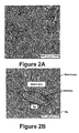
- FIGS. 2A and 2B are scanning electron micrographs (SEM) of an example energy harvesting element.
- FIG. 3 is a schematic of an example IPMC beam with electrodes.
- FIG. 4 is a schematic representation illustrating example molecular chains and electrostatic forces along two neighboring cross-sections of a portion of an IPMC membrane.
- FIG. 5 is an example plot that illustrates deformation of a beam element along a neutral axis.
- FIG. 6 illustrates an example configuration of an IPMC power cell.
- FIG. 7 shows an example plot of a voltage time history of the IPMC power cell of FIG. 6 .
- FIG. 8 is an example plot that illustrates a comparison of a maximum root mean square (RMS) power output measured across a load of the configuration in FIG. 6 .
- RMS root mean square
- FIG. 9 is an example plot that illustrates RMS power (P rms ) output measured across the resistor load of the configuration in FIG. 6 .
- FIG. 10 is an example plot of a comparison of normalized RMS power output measured across the resistor load of the configuration in FIG. 6 for varying salt electrolyte concentrations.
- FIG. 11 is an example plot that illustrates a comparison of maximum power density for varying concentrations measured across the resistor load of the configuration in FIG. 6 .
- FIG. 12 is an example plot illustrating a comparison of RMS power efficiency of the power cell of FIG. 6 in air and in deionized water.
- FIG. 13 is an example plot illustrating a comparison of RMS power efficiency of the power cell of FIG. 6 in varying concentrations.
- FIG. 14 illustrates an example energy harvesting system.
- FIG. 15 is a flowchart that depicts example steps of preparing an IPMC power cell.
- systems and methods of harvesting and converting naturally occurring energy include exposing an active material to an ambient activation condition and harvesting at least a portion of energy that is created.
- energy harvesting from fluidic and flow environments or vibration can be accomplished using types of energy harvesters, such as flexible polymers.
- Active materials or Electro-Active Polymer (EAP)-metal composite thin films like Ionic Polymers, Piezoceramic materials, and electromagnetic systems may be used as mechanical to electrical energy transducers.
- EAP films respond to electrical stimulation with a change in shape and size and are classified based on actuation mechanism as electronic or ionic EAP.
- IPMC ionic polymer-metal composite
- the base polymer may be perfluorinated alkenes with short side-chains of ionic groups or styrene/divinylbenzene based with substituted ionic groups.
- Perfluorinated alkenes have large polymer backbones and the side chains provide the ionic groups that interact with a solvent to produce active characteristics.
- Styrene polymers take ionic groups from the phenyl rings to produce active mechanism.
- a base for the IMPCs is Nafion R 117 (DuPont®), which is a perfluorosulfonic acid polymer.
- the base may be Flemion, or other polystyrene polymers.
- Nafion is slender, flexible, rugged and can sustain large strains making the material useful for high stress environments. The ability to endure large strains also allows Nafion to have a large stroke that may be useful since operating frequencies are estimated to be between about 0.2 and about 4.2 Hz, for example.
- Nafion IPMC may be used as a sustainable power generating source in different media such as air, deionized water, and ionic fluids, for example.
- Silver (Ag) nanoparticles sputtered on surfaces of the Nafion membrane may enhance power output in some examples.
- silver nanoparticle functionalized Ionic Polymer-Metal composite IPMC
- IPMC Ionic Polymer-Metal composite
- MEMS microelectronic and microelectromechanical systems
- Embodiments described herein may be used to power biological implants using electrical power harvested from blood flow, powering wireless sensors, and wearable devices, for example.
- an IPMC including a thin polyelectrolyte membrane of EAP can be plated on both faces by a noble metal, such as platinum (Pt) or silver (Ag), and may be neutralized with an amount of counter ions to balance a charge of anions covalently bonded to the EAP membrane.
- a noble metal such as platinum (Pt) or silver (Ag)
- electromechanical coupling is ionic diffusion, which includes motion of mobile cations.
- Ionic polymers have both fixed anions and mobile cations. When the material is hydrated, the cations diffuse toward an electrode on a surface of the material under an applied electric field. Inside the polymer structure, anions in interconnected clusters provide channels for the cations to flow toward the electrode.
- This motion of ions causes the polymer structure to bend toward the anode. Bending the ionic polymers will also force ion diffusion and produce voltage, which can be measured or collected through electrodes.
- an electric potential is developed. Energy may be harvested from these motions using capacitors and AC/DC converters to produce sustainable power, for example.
- FIG. 1A illustrates a side view of an energy harvesting element 100 including a polymer 102 coated with an electrode 104 and 106 on either side of the polymer 102 .
- the polymer 102 may be a rectangular shape and include the electrode 104 and 106 coating on opposing sides of a length of the polymer 102 .
- the polymer 102 may be a polystyrene backbone membrane, such as Nafion or Flemion, for example.
- the electrodes 104 and 106 may be noble metals, such as platinum, gold, or silver, for example.
- Using a dispersion technique to coat the polymer 102 also allows the electrodes 104 and 106 to cover a large surface area of the polymer 102 .
- using silver as the electrodes 104 and 106 may lead to better oxidation of counter-ions in an electrolyte.
- silver atoms have filled d-orbitals with energy below Fermi energy leading to good oxidation of counter-ions in the electrolyte.
- silver may provide enhanced hydration of the membrane due to the polystyrene backbone of Ag coating and random spaces. Other materials may be used to coat the membrane as well.
- platinum has incompletely filled d-orbital and an energy exceeding the Fermi energy level, which may lead to relatively less oxidation and hence less possible energy to harvest.
- a combination of platinum and silver may be used as the electrode coating.
- FIG. 1A two elongated surfaces of the polymer 102 are shown to be entirely coated with the electrode 104 and 106 . However, in other embodiments, only a portion of surfaces of the polymer 102 may be coated, or only one surface or a portion of one surface may be coated with an electrode coating. Placement of the coating and an amount of the coating may vary depending on an application of the energy harvesting element.
- the electrode coating 104 and 106 may be deposited in channels of the polymer 102 .
- channels less than about one centimeter wide may be present lengthwise along the polymer 102 from one end to the other end, and may be about 2-3 cm long.
- the silver electrodes 104 and 106 may be deposited in the channels to form a substantially uniform coating on a surface of the polymer 102 . Due to the individual channels, the coating of the electrode may include texture.
- the electrode coating 104 and 106 may be of a thickness of about 0.1 cm (or less than about 10 microns), for example.
- a flow of charge in the energy harvesting element 100 may be from the electrode 104 to the electrode 106 , or from the electrode 106 to the electrode 104 .
- a continuous flow of charge can be achieved with a substantially uniform silver electrode coating, for example, when the energy harvesting element 100 is subjected to an actuation environment, such as within a flow of sea water.
- the electrode coating 104 and 106 may be spaced away from edges of the polymer 102 edges by about 1-4 mm, for example.
- a mask may be placed on the polymer 102 over the edges, and the mask can be removed after application of the electrode. Sides of the polymer 102 may not include any electrode coating, for example.
- a connection to the electrodes 104 and 106 may be made at any location on the polymer to connect the energy harvesting element 100 to a circuit.
- a connection may be made from a top of the polymer 102 , and the connection may include a thin metal weld connection diffused to the polymer 102 , for example.
- FIG. 1B illustrates another embodiment of an energy harvesting element 108 including a polymer 110 in which only one side of the polymer 110 includes an electrode coating 112 .
- the other side of the polymer 110 includes a graphitic or carbon coating 114 , for example.
- the energy harvesting element 108 may be used as a fuel cell, for example.
- the energy harvesting element 108 may be a hybrid type device. In such a hybrid device, the polymer 110 can undergo bending.
- an anode or metal based electrode e.g., electrode coating 112
- porous channels will allow hydrogen to flow inside the perfluorinated membrane of the polymer 110 .
- a second electrode e.g., graphitic or carbon coating 114
- oxygenation will be required.
- a second electrode e.g., graphitic or carbon coating 114
- hydrogen ions coming through the perfluorinated backbone of the polymer 108 will react with oxygen.
- current will flow in an outer circuit between the cathode to anode and water will be produced due to the hydrolysis type reaction.
- Such a hybrid device with two outer electrodes 112 and 114 along with a deformable perfluorinated membrane 110 will produce a current that is a combination of hydrogen ion migration and resulting proton exchange via hydrolysis, in addition to the bending deformation induced charge previously explained.
- FIG. 1C is an example optical micrograph of a cross-section of the energy harvesting element 100 including an Ag-coated Nafion membrane.
- the polymer 102 is shown with a uniform coating of silver electrodes 104 and 106 on both sides of the polymer 102 .
- FIGS. 2A and 2B are example scanning electron micrographs (SEM) of the energy harvesting element 100 of FIG. 1A that illustrate surface morphology of the element at an interface of the Ag based electrode and the base polymer membrane of Nafion, for example.
- SEM scanning electron micrographs
- FIG. 2A illustrates islands of Ag deposition upon the polymer membrane 102
- FIG. 2B illustrates the interface between the Ag electrode region and the bare polymer membrane 102 .
- the Ag coating may act as an electrode on the IPMC.
- the Ag electrode coating appears homogeneous and may develop micro-cracks within a first few cycles of deformation and islands of metal nanoparticles via migration, which then become stabilized.
- the interconnected islands of metal nanoparticles facilitate charge transport followed by saturation of the transport current intensity through electrical networks.
- bending of an IPMC creates a potential difference between electrodes of the IPMC. Electrostatic interaction between two neighboring polymeric chains is considered and electrostatic repulsion between asymmetrically distributed (about the middle plane) charges along different cross sections may lead to bending.
- a constitutive model expressing electromechanical behavior of an IPMC can be expressed as:
- ⁇ xx c ⁇ ⁇ ⁇ xx + g ⁇ ( ⁇ xx , ⁇ ⁇ ⁇ x , ⁇ c ) Equation ⁇ ⁇ ( 1 )
- g ⁇ ( ⁇ xx , ⁇ ⁇ ⁇ x , ⁇ c ) is the eigenstress developed and an explicit form is derived by considering electrostatic interactions between polymer chains.
- a charge distribution along a cross-section of the IPMC is derived due to applied potential.
- a small boundary layer of accumulated positive ions may develop, which is a function of the applied voltage.
- Ionic flux due to motion of the charge across the cross-section is proportional to a charge density gradient, electric potential gradient, pressure gradient, and velocity of water molecules. The ionic flux is given by:
- J + - D + ⁇ ( ⁇ C + ⁇ z + C + ⁇ F RT ⁇ ⁇ ⁇ ⁇ z + C + ⁇ V + ⁇ RT ⁇ ⁇ p ⁇ z ) + C + ⁇ v Equation ⁇ ⁇ ( 2 )
- J + , D + , C + , ⁇ , T, R, v, p, V + ⁇ . . . and z are the ionic flux, ionic diffusivity coefficient, positive ion charge density, electric potential, temperature, gas constant, velocity of water molecules, pressure, molar volume, and thickness coordinate along the cross-section, respectively.
- the ionic flux due to pressure gradient and flow of water molecules is considered negligible. Hence, only the first two terms of Equation (2) are considered.
- FIG. 3 An example schematic of an IPMC beam 300 with electrodes 302 and 304 is shown in FIG. 3 .
- charges are shown to transfer between the electrodes 302 and 304 through the IPMC 300 .
- Variation in potential is determined by using electrostatic equations given as:
- Equation (4) Equation (4)
- Equation (5) provides for a natural length scale l and a time scale ⁇ which characterizes a length of boundary layers and a relative speed of cation redistribution. These two scales are given by:
- ⁇ an average electric permittivity of the of the IPMC beam.
- ⁇ an average electric permittivity of the of the IPMC beam.
- a time-independent equilibrium ion distribution is given by setting the ionic flux as zero.
- Upon application of a potential there is an asymmetric distribution of charge with respect to a middle plane of the beam. This results in development of a cation depleted boundary layer.
- Charge density in the cation depleted layer is constant and is given by ( ⁇ C ⁇ F), and in the remaining membrane, the charge density is (C+ ⁇ C ⁇ )F.
- a thickness of the boundary layer is taken to be l′.
- An electric field E(z) in a region ⁇ h ⁇ z ⁇ ( ⁇ h+l′) is obtained by solving:
- Equation (10) Solution of Equation (10) is of the form:
- the terms ⁇ 0 , A 0 , l′, B 0 , B 1 , B 2 are integration constants which are calculated from boundary conditions, continuity conditions, and overall charge balance conditions.
- FIG. 4 is an example schematic representation illustrating molecular chains and electrostatic forces along two neighboring cross-sections of a portion of an IPMC membrane. Using FIG. 4 , the force of repulsion due to a charge distribution on one cross-section on the charge distribution across another cross section can be obtained as:
- Equation 12 Equation 12
- Equation (18) Equation (17)
- FIG. 5 is an example plot that illustrates deformation of a beam element along a neutral axis.
- CD which is of length ds located at a distance s from the origin O of the (x, z) system as shown in FIG. 5 .
- CD moves to C*D*.
- the displacement components of C and D are denoted by (u,w) and (u+du, w+dw), respectively.
- the strain e at point C can be calculated as:
- FIG. 6 illustrates an example configuration of an IPMC power cell 600 .
- the IPMC power cell 600 may be a silver nanoparticle coated IPMC power cell.
- the silver nanoparticle based electrode layer on the IPMC film surfaces act as electrodes as well as efficient charge carriers.
- the IPMC power cell 600 may be prepared by preparing a surface of an IPMC strip using ultrasonication followed by electro-chemical etching under elevated temperature. Silver nanoparticle based binding layers are then made on surfaces of the IPMC strip using a sol-gel process.
- the IPMC power cell 600 includes two copper plates 602 and 604 as end clamps acting as leads on opposing sides of the IPMC power cell 600 at one end. Two electrically insulating poly-propylene strips (not shown) can be used to grip the copper plates 602 and 604 .
- the pair of copper plates 602 and 604 perform as the electrical interconnects.
- the IPMC power cell 600 may be a strip of IPMC (Nafion) membrane of dimensions of about 0.4 cm ⁇ about 0.2 cm ⁇ about 0.1 mm. As another example, the IPMC power cell 600 may include dimensions of about 5.2 cm ⁇ about 2 cm ⁇ about 0.1 cm. The IPMC power cell 600 may be of other lengths, widths, and heights, or be in ranges of between about 0.4 cm-5.2 cm ⁇ about 0.2 cm-2 cm ⁇ about 0.1 mm-0.1 cm, for example. The IPMC power cell 600 may weigh about 0.3 g. In example embodiments, the IPMC power cell 600 may be any electroactive polymer, ionic polymer, or piezoelectric polymer composites, and includes an electrode coating, such as a silver electrode coating.
- a load 606 such as a resistive load of 1 MOhms, can be connected in series with the IPMC power cell 600 to utilize energy generated by the IPMC power cell 600 .
- the example value of electrical resistance is chosen as this is comparable to internal impedance of the IPMC strip, for example.
- the IPMC power cell 600 is connected to a stepper motor 608 (e.g., via an aluminum extension not shown).
- the stepper motor 608 can be driven using a BJT current amplifier, for example.
- a control input to the stepper motor 600 can be triggered via a micro-controller that instructs the stepper motor 608 to rotate in a clockwise direction for a given time interval and to rotate in an anticlockwise direction for the same time interval.
- This movement establishes an oscillatory or flapping type motion of the IPMC power cell 600 .
- Variation in amplitude and frequency of oscillations is obtained by modifying movement of the stepper motor 608 .
- a frequency is changed by varying internal delay between each step of the stepper motor 608 .
- An oscillation amplitude is modified by varying a duty cycle of rotational motion in each direction.
- the oscillations of the stepper motor 608 are adjusted so that the motion is approximately centered to a vertical plane and so that there are equal deflections in both directions.
- the IPMC power cell 600 is placed within a solution (e.g., a salt electrolyte solution of various concentrations or de-ionized water) and the motion of the stepper motor 608 is applied. A maximum deflection of the stepper motor 306 maintains the IPMC power cell 600 immersed in the solution. After connecting leads to the resistive load, a voltage across the resistive load is measured. Electromagnetic shielding can be used to reduce or eliminate noise in the measured voltage. In FIG. 6 , ⁇ is a maximum angular displacement of the IPMC power cell 600 from a mean position.
- a solution e.g., a salt electrolyte solution of various concentrations or de-ionized water
- the Ag-coated IPMC power cell 600 in this example has a surface area of about 10.4 cm 2 (5.2 cm ⁇ 2 cm).
- Experiments were performed in air, deionized water, and sodium chloride (NaCl) electrolyte with NaCl concentrations of about 5 g/l, about 19 g/l, and about 35 g/l.
- NaCl sodium chloride
- the highest concentration of 35 g/l chosen substantially corresponds to salt concentration in sea water.
- the IPMC power cell 600 generates energy due to a motion of charges between the silver electrode coatings through the Nafion polymer, for example.
- the motion of charges can be increased by hydrating the IPMC power cell 600 .
- the motion of charges leads to a current and a potential difference between the two sides (e.g., electrodes) of the IPMC power cell 600 .
- any type of circuit may be connected to the IPMC power cell 600 to utilize the energy, such as the load 606 illustrated in FIG. 6 .
- capacitors may be connected to the IPMC power cell 600 to store the charge that is generated, for example.
- FIG. 7 shows an example plot of a voltage time history of the IPMC power cell 600 over a time interval of 1.5 seconds at a frequency of about 10.2375 Hz.
- the plot indicates the mechanical behavior of the IPMC power cell 600 and the fluid structure interaction at a particular frequency.
- an output wave has a double sinusoidal characteristic, which implies induced secondary harmonics in the IPMC power cell 600 possibly due to stepper motor loading and the fluid structure interaction, for example.
- voltage generated by the IPMC power cell 600 may be in a range of hundreds of mV for a 1 Mohm resistive load, which can be significant in context of powering wireless communication devices, for example.
- FIG. 8 is an example plot that illustrates a comparison of a maximum root mean square (RMS) power output measured across the 1 Mohm resistor in air and in deionized water.
- RMS root mean square
- FIG. 8 illustrates that the IPMC power cell 600 in a hydrated state generates higher power at low frequencies and a maximum power P max generated in deionized water is an order of magnitude higher than P max generated in air.
- FIG. 8 illustrates that in air P max remains constant at higher frequencies, for example.
- the IPMC power cell 600 may provide such output power levels due to increased concentration of water molecules in the diffused Ag-electrode-Nafion interface, for example, which contributes to an increase in charge carriers (e.g., protons).
- charge carriers e.g., protons
- the IPMC power cell 600 may be operated at frequencies of about 0.2 Hz to about 4.2 Hz to obtain a high power output.
- This frequency range may be optimum for the chosen size of the membrane in this experiment (e.g., about 0.4 cm ⁇ about 0.2 cm ⁇ about 0.1 mm).
- this frequency range can be scaled by scaling the geometry and size of the membrane.
- FIG. 9 is an example plot that illustrates RMS power (P rms ) output measured across the resistor load normalized with respect to an approximate measure of peak deflection bL sin ⁇ against frequency, where L is a length and b is a width of IPMC power cell 600 , and ⁇ denotes a maximum angular displacement of a root of the IPMC power cell 600 from a mean position.
- the normalized quantity gives an approximate estimate of power generated per unit deformation induced mechanically.
- a peak normalized P rms for the IPMC power cell 600 in air is about 0.1 nW/cm 2 , while in deionized water the peak normalized P rms reaches a value of about 9.125 nW/cm 2 .
- FIG. 10 is an example plot of a comparison of normalized RMS power output measured for varying salt electrolyte concentrations across the 1 Mohm load connected in series with the oscillating IPMC power cell 600 .
- the plot shows a trend of decreasing P rms with increasing frequency for each salt concentration.
- the plot also illustrates a degradation in performance with an increase in the salt concentration.
- the reduction in P rms may be due to increased localization of sodium (Na) ions around and within the IPMC power cell 600 leading to a mechanical damping and result in reduced bending load.
- FIG. 11 is an example plot that illustrates comparison of maximum power density for varying NaCl concentrations measured across the load of 1 M ⁇ connected in series with the oscillating IPMC power cell 600 .
- the plot shows frequency dependence of P max for various different concentrations of NaCl.
- An increase in P max indicates that power generation of the IPMC power cell 600 is higher in the presence of liquid electrolyte.
- a maximum power density of about 52.91 ⁇ W/kg is obtained for the 5 g/L NaCl electrolyte, and, for the 20 g/L and 35 g/L NaCl electrolytes, P max is found to be about 29.63 ⁇ W/kg and about 12.99 ⁇ W/kg, respectively.
- IPMC power cell 600 decreases with an increase in frequency and with an increase in concentration of the electrolyte.
- the plot illustrates that P max nearly halves for every 15 g/L increase in concentration of electrolyte. This behavior of a reduction of P max may be due to presence of large sized ions of the NaCl electrolyte. These ions agglomerate around the electrode islands on the Nafion membrane and mechanically dampen the vibrating IPMC power cell 300 resulting in a reduction of P max .
- the power density is better for low concentrations of NaCl and good enough to enhance cation transport.
- a more impermeable interface between the electrolyte and the Nafion polymer membrane forms, which further hinders transport. That is, with the presence of increasing Na ions, the Hydrogen ions in the sulphonic group of Nafion are replaced with Na ions to form cluster of dipoles. A cluster diameter of Na ions (4.21 nm) is less than Hydrogen ions (4.74 nm).
- a smaller cluster diameter results in a lower stiffness of the material, and leads to a lesser input energy and higher power efficiency.
- the cluster morphology has an effect on the macroscopic electro-mechanical properties, and also has an effect on ion transport properties of hydrated Nafion. This is evident from FIG. 11 where at an increased concentration of NaCl, the polymer electrolyte interface formed with Na further reduces ionic conductivity of the lamellar structure of Nafion.
- the energy harvesting IPMC power cell when the energy harvesting IPMC power cell is immersed in an electrolyte solution, power output increases as compared to power output in deionized water or air.
- the copper contacts 602 and 604 of the IPMC power cell 600 do not interact with the electrolytes in any substantial amount, and thus, do not contribute to the power output in any substantial amount.
- silver is a noble metal and does not react with the NaCl solution (in any substantial manner), and thus, no red-ox reactions between electrodes and electrolytes occur.
- the output power is due to the IPMC power cell 600 and motion of the IPMC power cell 600 .
- a model is described to determine an induced potential on a surface of an IPMC power cell due to a bending deformation. For example, power conversion efficiency of the IPMC immersed in a fluid can be computed. Linear forced vibration analysis may be performed using fluid loading induced nonlinearity in a forcing term.
- the power cell 600 is fixed at one end and immersed in a fluid.
- the power cell 600 is rotated at its root by an angle ⁇ (t) at a given time t due to which a certain volume of fluid becomes displaced.
- a total pressure is a summation of static and dynamic pressure, and is given by:
- EI ⁇ ⁇ 4 ⁇ w ⁇ ( x ′ , t ) ⁇ x ′ 4 ⁇ [ ⁇ max ⁇ b ⁇ ⁇ ⁇ ⁇ ⁇ g ⁇ ⁇ sin ⁇ ( ⁇ 0 ⁇ t ) ] ⁇ x ′ + ⁇ [ - 1 2 ⁇ C f ⁇ ⁇ max ⁇ ⁇ 0 2 ⁇ sin 2 ⁇ ( ⁇ 0 ⁇ t ) ] ⁇ x ′ 2 ⁇
- EI ⁇ ⁇ 4 ⁇ w ⁇ ( x ′ , t ) ⁇ x ′ 4 ⁇ f 1 ⁇ ( t ) ⁇ x ′ + f 2 ⁇ ( t ) ⁇ x ′ 2 ⁇ f 2 ⁇ ( t ) ⁇ x ′ 2 , Equation ⁇ ⁇ ( 27 )
- E is the Young's modulus
- I is a second area moment of the power
- the bending strain in the power cell 600 is given by:
- a total work density at any given point of time t is obtained by integrating over the volume as:
- Input RMS power can also be computed.
- a mechanical input RMS power leading to bending of the power cell 600 also includes power required to overcome skin friction.
- FIG. 12 is an example plot illustrating comparison of RMS power efficiency of an Ag-based IPMC power cell (such as the IPMC power cell 600 ) in air and in deionized water.
- the plot shows that an increase in density of the medium leads to higher deformation and hence higher input power, and output power also increases, leading to higher efficiency of power conversion in water as compared to air.
- the plot also illustrates that at lower frequencies, power efficiency is higher.
- the power cell may be used for tidal and other hydrodynamic energy harvesting applications.
- FIG. 13 is an example plot illustrating comparison of RMS power efficiency of an Ag-based IPMC power cell (such as the IPMC power cell 600 ) in varying NaCl concentrations.
- the plot illustrates that with increases in the NaCl concentration, efficiency reduces gradually. This may be due to an increase in a number of Na + ions that block transport channels leading to decreases in efficiency, although input RMS power is more in the case of higher density (higher concentration of NaCl).
- an increased presence of Na + ions can accelerate micro-cracking of metal electrodes and Nafion interfaces leading to further degradation in efficiency over a number of cycles, for example.
- an energy harvesting element is in a form of a flexible thin film, and an area and shape of the film can be designed according to deformation mechanisms and source power intensity.
- Equation (36) According to an RMS power input due to fluid induced mechanical deformation, from Equation (36) it can be seen that:
- a multilayer stack of thin films can be used to prevent high bending forces.
- a stack of thin films may act as a single homogenous device with outermost surface electrodes that can be actuated using a single source of energy.
- a stack of thin films will have layers of IPMCs with two separated electrodes such that a current will be added in parallel (with proper arrangement to avoid back-flow into neighboring IPMCs).
- multiple IPMC power cells may be combined and connected in series. When different devices are connected in series to amplify output voltage, the devices may require many/distributed sources of energy, for example. Use of multiple layers of thin films in an IPMC power cell, or use of multiple IPMC power cell will depend on the application.
- an IPMC coated with an Ag based electrode enhances charge transport under bending load.
- Results of RMS power efficiency calculations indicate that an efficient conversion of mechanical energy to electrical energy by the IPMCs under cyclic bending deformation depends on morphology of metal electrodes that facilitate charge transport and also on an amount of a competing cluster of ions in the electrolyte medium, for example.
- Nonconventional body placeable (bending-stretching of the embedded IPMC in open air and room temperature) or implantable sensors (IPMC in fluidic environment) may include small, flexible, long-lasting energy convertors.
- clusters of sensors may be interwoven into textiles for use in shirts, belts, shoes, headgear, and other apparel.
- Bio-medical implant devices and associated electronic control systems can also be powered using fluidic embedded IPMCs undergoing bending strain due to deformation of organs and limbs in the human body.
- IPMCs can be an integral part of a host structure such as implant, hemodynamic devices, blood flow in arteries, valve, clothing, energy harvesting from pipe flow in sewage environment, pipe flow in home appliances, and several other applications, for example.
- IPMC based energy harvesting systems may be used for applications including tidal wave energy harvesting, residual environmental energy harvesting to power MEMS and NEMS devices, and sensors and actuators for biomedical, aerospace and oceanic applications, for example.
- an energy harvesting system may be used to harvest energy from an IPMC.
- FIG. 14 illustrates an example energy harvesting system.
- the system may include a structure 1400 housing an energy harvesting element 1402 .
- the structure may be positioned to receive environmentally created vibrations, and may be designed according to a type of environmentally created vibration to be received.
- the system may further include a device 1404 in communication with the energy harvesting element 1402 to harvest energy.
- the device 1404 may be any type of device and varies depending on an application of the system.
- the device 1404 may be connected to the energy harvesting element 1402 through leads, for example.
- a power cell such an IPMC power cell
- FIG. 15 is a flowchart that depicts example steps of preparing an IPMC power cell.
- a base polymer membrane e.g., such as a Nafion membrane
- emery paper can be used to sand the membrane followed by ultrasonic washing of the membrane to remove any residue.
- the membrane may then be heat treated (e.g., boiled) in dilute hydrochloric acid (e.g., HCl 2N solution) for approximately 30 minutes, as shown at block 1504 , and then washed with deionized water, and shown at block 1506 .
- the membrane can again be boiled in deionized water to further remove any acidic content, as shown at block 1508 .
- a thin coating of metal electrodes are coated on either side of the membrane.
- the electrode coating may be spaced away from edges of the polymer edges by about 1 to about 4 mm, for example.
- a mask may be placed on the polymer over the edges, and the mask can be removed after application of the electrode, as shown at block 1510 . Sides of the polymer may not include any electrode coating.
- the electrode coating may be deposited, as shown at block 1512 .
- the electrodes may include homogenously dispersed silver nanoparticles (approximately 60% by weight) into polystyrene resin and a conductive hardener.
- the silver electrode may be dispersed on the polymer surface using a soft brush to ensure a uniform and consistent layer on the surface.
- Other methods of dispersion may include sol-gel methods, dip coating, sputtering, inkjet printing, or spin-coating, for example.
- Using a homogenously method of electrode deposition may result in better binding between the electrode and the base polymer as compared to what can be achieved using sputtering and electro-chemical deposition methods, for example.
- the binding between an electrode (e.g., the silver coating) and the polymer (e.g., the Nafion membrane) can be achieved using this dispersion process.
- a composition of the silver electrode may be in the range of about 40% to about 100% silver by weight, for example.
- Using pure silver e.g., about 100%
- using less than 100%, or about 40% or lower silver by weight may provide a predominantly polystyrene based mechanical backbone with good hydration and lesser charge collecting performance.
- An amount of silver by weight in the electrode may depend on an application and a desired power output.
- electrical leads or connection points may be included on the electrode coating, as shown at block 1514 , to enable attachment of devices to the IPMC power cell so as to harvest energy created by the IPMC power cell, for example.
- a range includes each individual member.
- a group having 1-3 cells refers to groups having 1, 2, or 3 cells.
- a group having 1-5 cells refers to groups having 1, 2, 3, 4, or 5 cells, and so forth.
Abstract
Description
where
is the eigenstress developed and an explicit form is derived by considering electrostatic interactions between polymer chains.
where J+, D+, C+, φ, T, R, v, p, V+ω. . . and z are the ionic flux, ionic diffusivity coefficient, positive ion charge density, electric potential, temperature, gas constant, velocity of water molecules, pressure, molar volume, and thickness coordinate along the cross-section, respectively. The ionic flux due to pressure gradient and flow of water molecules is considered negligible. Hence, only the first two terms of Equation (2) are considered.
where D, E, K are the electric displacement, electric field and electric permittivity, respectively. The continuity equation relating the ionic flux to charge density is given by:
Substituting of Equations (2) and (3) into Equation (4) provides:
Equation (5) provides for a natural length scale l and a time scale τ which characterizes a length of boundary layers and a relative speed of cation redistribution. These two scales are given by:
where
which gives:
where:
Solution of Equation (10) is of the form:
and solving for potential φ using Equation (3) gives:
and the charge density is given by:
The terms Ē0, A0, l′, B0, B1, B2 are integration constants which are calculated from boundary conditions, continuity conditions, and overall charge balance conditions. The continuity conditions at the boundary layer interface z=−h+l′ are as follows:
C +(−h′)=0 where h′=h−l′,
E (1)(−h′)=E (2)(−h′)
φ(1)(−h′)=φ(2)(−h′) Equation (13)
The end boundary conditions are:
φ(1)(−h′)=φ0/2
φ(2)(h′)=φ0/2
as shown in
Solving for the integration constants Ē0, A0, l′, B0, B1, B2 under the assumption that [a=h/l>>1] and [a′=h′/l′>>1] provides the constants as:
Since dq=ρcbdz, then the stress can be written as:
Substituting Equation (18) into Equation (17) provides:
Thus, the relationship between eigen stress and σxx e is:
where θ is the angle of rotation or euler angle of the beam.
With an assumption of inextensible neutral plane, e=0 thereby implying:
The Euler angle θ is related to u and w as:
The longitudinal strain is given by the relation:
The momentum conservation equation of the polymer beam is given by
Equation (25) can be solved with displacement and stress boundary conditions. Because of low stiffness and high power to weight ratios, IPMCs can be exploited to harness natural energy sources.
where θ(t)=θmax sin(ω0t), θmax is a maximum rotation applied at the root, (x′, z′) is the coordinate of a point along a rotated reference frame, b is a width of the power cell 600, ρ is a density of a surrounding medium, g is an acceleration due to gravity (relative acceleration is neglected), and Cf is a correction factor (a constant). Considering a time dependent effect in a calculation of dynamic power, and assuming that the effect of inertia is contributing to only kinetic energy and not any strain energy, an equation for elastic deformation of the power cell 600 is given by:
where E is the Young's modulus, I is a second area moment of the power cell 600 cross-section, and w is a transverse displacement of power cell 600. Since at any given point of time, input power depends mainly on a dynamic pressure and a differential static pressure cancels out under fully immersed conditions, the term f2(t)x′2 is the forcing term. Integrating Equation (27) with respect to x′ and by further simplification, the solution of the deflection of the power cell 600 is given by:
and bending stress in the power cell 600 can be approximated as:
σx′x′ =Eε x′x′ +μ{dot over (u)} Equation (30)
where μ is a dynamic viscosity with a corresponding velocity term contributing to skin friction, for example. Corresponding work density can be expressed as:
Upon simplification, Equation (32) becomes:
Using the above equations, input power required to deform the power cell 600 is given by:
where
While an input RMS power is approximately independent of viscosity (assuming Cf=1 for simplicity), the input RMS power is dependent on density of the medium.
where L is a length of the membrane, A is a surface area and h is a thickness. Power generated will be approximately directly proportional to the ninth power of length, directly proportional to surface area and inversely proportional to a cube of the thickness. This is a mechanical consideration assuming the membrane is oscillating as a cantilever structure immersed in fluid, for example. There may be other material considerations, such as that an actual charge transport mechanism may be slowed down due to a slow gradient when the thickness (e.g., distance between the surface electrodes) is larger, for example.
Claims (19)
Priority Applications (2)
| Application Number | Priority Date | Filing Date | Title |
|---|---|---|---|
| US12/718,159 US7982371B1 (en) | 2010-03-05 | 2010-03-05 | Polymer metal composite membranes |
| US13/161,218 US8508108B2 (en) | 2010-03-05 | 2011-06-15 | Polymer metal composite membranes |
Applications Claiming Priority (1)
| Application Number | Priority Date | Filing Date | Title |
|---|---|---|---|
| US12/718,159 US7982371B1 (en) | 2010-03-05 | 2010-03-05 | Polymer metal composite membranes |
Related Child Applications (1)
| Application Number | Title | Priority Date | Filing Date |
|---|---|---|---|
| US13/161,218 Continuation US8508108B2 (en) | 2010-03-05 | 2011-06-15 | Polymer metal composite membranes |
Publications (1)
| Publication Number | Publication Date |
|---|---|
| US7982371B1 true US7982371B1 (en) | 2011-07-19 |
Family
ID=44261916
Family Applications (2)
| Application Number | Title | Priority Date | Filing Date |
|---|---|---|---|
| US12/718,159 Expired - Fee Related US7982371B1 (en) | 2010-03-05 | 2010-03-05 | Polymer metal composite membranes |
| US13/161,218 Expired - Fee Related US8508108B2 (en) | 2010-03-05 | 2011-06-15 | Polymer metal composite membranes |
Family Applications After (1)
| Application Number | Title | Priority Date | Filing Date |
|---|---|---|---|
| US13/161,218 Expired - Fee Related US8508108B2 (en) | 2010-03-05 | 2011-06-15 | Polymer metal composite membranes |
Country Status (1)
| Country | Link |
|---|---|
| US (2) | US7982371B1 (en) |
Cited By (16)
| Publication number | Priority date | Publication date | Assignee | Title |
|---|---|---|---|---|
| US20110241490A1 (en) * | 2010-03-05 | 2011-10-06 | Indian Institute Of Science | Polymer Metal Composite Membranes |
| US20110270043A1 (en) * | 2010-04-30 | 2011-11-03 | Nellcor Puritan Bennett Llc | Air movement energy harvesting with wireless sensors |
| US20120004523A1 (en) * | 2010-06-30 | 2012-01-05 | R2Z Innovations, Inc. | System and methods for self-powered, contactless, self-communicating sensor devices |
| CN102931876A (en) * | 2012-09-12 | 2013-02-13 | 北京航空航天大学 | Intelligent material ion-exchange polymer metal composite (IPMC)-based miniature power generation device |
| US20150028725A1 (en) * | 2011-07-18 | 2015-01-29 | Renault S.A.S. | Method of assembling an ultrasonic transducer and the transducer obtained thereby |
| US9913321B2 (en) * | 2013-01-25 | 2018-03-06 | Energyield, Llc | Energy harvesting container |
| EP3232559A4 (en) * | 2015-01-16 | 2018-08-15 | The University of Tokyo | Vibration power generation element |
| US10079561B1 (en) * | 2016-04-09 | 2018-09-18 | Face International Corporation | Energy harvesting components and devices |
| US10249810B2 (en) | 2017-04-10 | 2019-04-02 | Face International Corporation | Structurally embedded and inhospitable environment systems and devices having autonomous electrical power sources |
| CN110061530A (en) * | 2019-04-22 | 2019-07-26 | 重庆邮电大学 | A kind of electric field energy acquisition power supply applied to 220V power line |
| US10553774B2 (en) | 2016-04-09 | 2020-02-04 | Face International Corporation | Methods for fabrication, manufacture and production of energy harvesting components and devices |
| US10896929B2 (en) | 2016-04-09 | 2021-01-19 | Face International Corporation | Integrated circuit components incorporating energy harvesting components/devices, and methods for fabrication, manufacture and production of integrated circuit components incorporating energy harvesting components/devices |
| US10985677B2 (en) | 2017-04-10 | 2021-04-20 | Face International Corporation | Systems and devices powered by autonomous electrical power sources |
| US11362138B2 (en) | 2016-04-09 | 2022-06-14 | Face International Corporation | Devices and systems incorporating energy harvesting components/devices as autonomous energy sources and as energy supplementation, and methods for producing devices and systems incorporating energy harvesting components/devices |
| US11375912B2 (en) * | 2018-09-18 | 2022-07-05 | Northwestern University | Liquid flow induced power generation using nanoscale metal layers |
| US11957053B2 (en) | 2021-07-19 | 2024-04-09 | Face International Corporation | Methods for fabrication, manufacture and production of an autonomous electrical power source |
Families Citing this family (13)
| Publication number | Priority date | Publication date | Assignee | Title |
|---|---|---|---|---|
| US9369105B1 (en) | 2007-08-31 | 2016-06-14 | Rf Micro Devices, Inc. | Method for manufacturing a vibrating MEMS circuit |
| US9385685B2 (en) * | 2007-08-31 | 2016-07-05 | Rf Micro Devices, Inc. | MEMS vibrating structure using an orientation dependent single-crystal piezoelectric thin film layer |
| US9391588B2 (en) * | 2007-08-31 | 2016-07-12 | Rf Micro Devices, Inc. | MEMS vibrating structure using an orientation dependent single-crystal piezoelectric thin film layer |
| US9466430B2 (en) | 2012-11-02 | 2016-10-11 | Qorvo Us, Inc. | Variable capacitor and switch structures in single crystal piezoelectric MEMS devices using bimorphs |
| CN103076364B (en) * | 2012-12-31 | 2015-12-23 | 上海师范大学 | A kind of IPMC diaphragm sensing characteristics measurement mechanism and method |
| CN103151453A (en) * | 2013-03-12 | 2013-06-12 | 南京航空航天大学 | Preparation method of IPMC (ion polymer metal composite) electric actuating material with micro nano surface texture |
| KR101433309B1 (en) | 2013-03-26 | 2014-08-22 | 인제대학교 산학협력단 | Power generation device of offshore floating type using ipmc |
| CN103618474B (en) * | 2013-11-15 | 2016-03-02 | 南京航空航天大学 | The straight line driving mechanism driven based on IPMC and linear actuator |
| US9991872B2 (en) | 2014-04-04 | 2018-06-05 | Qorvo Us, Inc. | MEMS resonator with functional layers |
| US9998088B2 (en) | 2014-05-02 | 2018-06-12 | Qorvo Us, Inc. | Enhanced MEMS vibrating device |
| CN105066863B (en) * | 2015-08-04 | 2019-01-25 | 上海交通大学 | Displacement sensor based on electroactive elastomer polymer |
| US11114955B2 (en) | 2017-11-17 | 2021-09-07 | Clemson University | Self powered wireless sensor |
| KR102443898B1 (en) * | 2018-11-12 | 2022-09-15 | 주식회사 엘지에너지솔루션 | A battery pack charge system configured to prevent overcharge and A vehicle comprising the same |
Citations (16)
| Publication number | Priority date | Publication date | Assignee | Title |
|---|---|---|---|---|
| US3282875A (en) | 1964-07-22 | 1966-11-01 | Du Pont | Fluorocarbon vinyl ether polymers |
| US6682500B2 (en) * | 1998-01-29 | 2004-01-27 | David Soltanpour | Synthetic muscle based diaphragm pump apparatuses |
| US6935263B1 (en) * | 2004-06-07 | 2005-08-30 | The United States Of America As Represented By The Secretary Of The Navy | Wake absorber |
| US7240655B2 (en) * | 2004-05-26 | 2007-07-10 | Sri International | Compliant walled combustion devices II |
| US20080093849A1 (en) * | 2004-05-26 | 2008-04-24 | Sri International | Compliant walled combustion devices for producing mechanical and electrical energy |
| WO2008064689A2 (en) * | 2006-11-28 | 2008-06-05 | University Of Tartu | A shape changing manipulator comprising self-sensing actuators made of an electroactive polymer material |
| US20090050487A1 (en) * | 2006-03-16 | 2009-02-26 | Fang Nicholas X | Direct Nanoscale Patterning of Metals Using Polymer Electrolytes |
| US20090105400A1 (en) * | 2006-02-07 | 2009-04-23 | Daikin Industries, Ltd. | Fluorine-containing polymer having heteroaromatic ring |
| WO2009063610A1 (en) * | 2007-11-13 | 2009-05-22 | Kohei Hayamizu | Power generation unit |
| US20090184923A1 (en) * | 2000-05-24 | 2009-07-23 | Immersion Corporation, A Delaware Corporation | Haptic Stylus Utilizing An Electroactive Polymer |
| US20090241537A1 (en) * | 2008-03-31 | 2009-10-01 | Gm Global Technology Operations, Inc. | Energy harvesting, storing, and conversion utilizing shape memory activation |
| US20100044212A1 (en) * | 2008-08-21 | 2010-02-25 | Snu R&Db Foundation | Vertically standing ionic polymer-metal composite |
| US20100055378A1 (en) * | 2008-08-26 | 2010-03-04 | Snu R&Db Foundation | Encapsulated ionic polymer-metal composite device |
| US20100148164A1 (en) * | 2008-12-15 | 2010-06-17 | Stmicroelectronics S.R.L. | All-organic sensor/actuator system |
| US20100164330A1 (en) * | 2006-02-03 | 2010-07-01 | Daikin Industries, Ltd | Actuator element |
| US20100271755A1 (en) * | 2009-04-22 | 2010-10-28 | Bozena Kaminska | Ionic polymer metal composite capacitor |
Family Cites Families (8)
| Publication number | Priority date | Publication date | Assignee | Title |
|---|---|---|---|---|
| JPS54112785A (en) * | 1978-02-24 | 1979-09-03 | Asahi Glass Co Ltd | Electrode and manufacture thereof |
| EP2037511A3 (en) * | 2003-09-24 | 2009-04-22 | Kyocera Corporation | Multilayer piezoelectric element |
| US7695647B2 (en) * | 2005-06-09 | 2010-04-13 | University Of Maryland | Electrically conductive metal impregnated elastomer materials and methods of forming electrically conductive metal impregnated elastomer materials |
| JP4732876B2 (en) * | 2005-11-30 | 2011-07-27 | 株式会社日立製作所 | Actuator, actuator module, and actuator module manufacturing method |
| FR2924359B1 (en) * | 2007-11-30 | 2010-02-12 | Commissariat Energie Atomique | PROCESS FOR PREPARING DEPOSITION OF METAL NANOPARTICLES BY PHYSICAL VAPOR DEPOSITION |
| JP5473483B2 (en) * | 2009-08-27 | 2014-04-16 | キヤノン株式会社 | Actuator |
| US7982371B1 (en) * | 2010-03-05 | 2011-07-19 | Indian Institute Of Science | Polymer metal composite membranes |
| EP2577759A4 (en) * | 2010-06-02 | 2015-04-29 | Indian Inst Scient | Energy harvesting devices using carbon nanotube (cnt)-based electrodes |
-
2010
- 2010-03-05 US US12/718,159 patent/US7982371B1/en not_active Expired - Fee Related
-
2011
- 2011-06-15 US US13/161,218 patent/US8508108B2/en not_active Expired - Fee Related
Patent Citations (16)
| Publication number | Priority date | Publication date | Assignee | Title |
|---|---|---|---|---|
| US3282875A (en) | 1964-07-22 | 1966-11-01 | Du Pont | Fluorocarbon vinyl ether polymers |
| US6682500B2 (en) * | 1998-01-29 | 2004-01-27 | David Soltanpour | Synthetic muscle based diaphragm pump apparatuses |
| US20090184923A1 (en) * | 2000-05-24 | 2009-07-23 | Immersion Corporation, A Delaware Corporation | Haptic Stylus Utilizing An Electroactive Polymer |
| US7240655B2 (en) * | 2004-05-26 | 2007-07-10 | Sri International | Compliant walled combustion devices II |
| US20080093849A1 (en) * | 2004-05-26 | 2008-04-24 | Sri International | Compliant walled combustion devices for producing mechanical and electrical energy |
| US6935263B1 (en) * | 2004-06-07 | 2005-08-30 | The United States Of America As Represented By The Secretary Of The Navy | Wake absorber |
| US20100164330A1 (en) * | 2006-02-03 | 2010-07-01 | Daikin Industries, Ltd | Actuator element |
| US20090105400A1 (en) * | 2006-02-07 | 2009-04-23 | Daikin Industries, Ltd. | Fluorine-containing polymer having heteroaromatic ring |
| US20090050487A1 (en) * | 2006-03-16 | 2009-02-26 | Fang Nicholas X | Direct Nanoscale Patterning of Metals Using Polymer Electrolytes |
| WO2008064689A2 (en) * | 2006-11-28 | 2008-06-05 | University Of Tartu | A shape changing manipulator comprising self-sensing actuators made of an electroactive polymer material |
| WO2009063610A1 (en) * | 2007-11-13 | 2009-05-22 | Kohei Hayamizu | Power generation unit |
| US20090241537A1 (en) * | 2008-03-31 | 2009-10-01 | Gm Global Technology Operations, Inc. | Energy harvesting, storing, and conversion utilizing shape memory activation |
| US20100044212A1 (en) * | 2008-08-21 | 2010-02-25 | Snu R&Db Foundation | Vertically standing ionic polymer-metal composite |
| US20100055378A1 (en) * | 2008-08-26 | 2010-03-04 | Snu R&Db Foundation | Encapsulated ionic polymer-metal composite device |
| US20100148164A1 (en) * | 2008-12-15 | 2010-06-17 | Stmicroelectronics S.R.L. | All-organic sensor/actuator system |
| US20100271755A1 (en) * | 2009-04-22 | 2010-10-28 | Bozena Kaminska | Ionic polymer metal composite capacitor |
Non-Patent Citations (23)
| Title |
|---|
| B. Ahish, et al., "Coupled electro-mechanical response of an electroactive polymer cantilever structure and its application in energy harvesting,", Proc. of SPIE Smart Structures/NDE Conference, Mar. 8-12, 2009, San Diego, California, USA, 7287, 2009. |
| Bar-Cohen Y, "Electroactive Polymer (EAP) Actuators as Artificial Muscles-Reality, Potential,and Challenges" SPIE Press, Bellingham, WA, 2001, chapter 1. |
| Brian Landi J, Ryne Raffaelle P, Michael Heben J, Jeffrey Alleman L, Vanderveer W, and Gennett T 2002 Single Wall Carbon Nanotube-Nafion Composite Actuators Nano Letters 211 1329-1332. |
| Brufau-Penella J, Puig-Vidal M, Giannone P, Graziani S and Strazzeri S 2008 Characterization of the harvesting capabilities of an ionic polymer metal composite device Smart Materials and Structures 17 015009. |
| Chandrakasan A, Amirtharajah R, Cho S H, Goodman J. Konduri G, Kulik J, Rabiner W, and Wang A 1999 Design Considerations for Distributed Microsensor Systems Proceedings of the 21st IEEE Annual Custom Integrated Circuits Conference 279-286. |
| Ericka M, Vasic D, Costa F and Poulain G 2006 Predictive energy harvesting from mechanical vibration using a circular piezoelectric membrane IEEE Ultrasonics Symposium 2005 2 946-949. |
| Farinholt K and Leo D J 2004 Modeling of Electromechanical charge sensing in Ionic polymer transducers Mechanics of Materials 36 421-433. |
| Johnson T J, et al., " Energy harvesting from mechanical vibrations using piezoelectric cantilever beams", Proceedings of SPIE, vol. 6169, (2004) pp. 61690D-1-61690D-12. |
| Kang I, Heung Y Y, Jay Kim H, Lee J W, Gollapudi R, Subramaniam S, Narasimhadevara S, Hurd D, Kirikera G R, Shanov V, Schulz M J, Shi D, Boerio J, Mall S and Ruggles-Wren M 2006 Introduction to carbon nanotube and nanofiber smart materials Composites : Part B 37 382-394. |
| Kim H W, et al., "Energy harvesting using a piezoelectric cymbal transducer in dynamic environment", Japanese Journal of Applied Physics, vol. 43, (2004) pp. 6178-6183. |
| Kundu S, Leonardo Simon C, Fowler M and Grot S 2005 Mechanical properties of Nafion electrolyte membranes under hydrated conditions Polymer 46 11707-11715. |
| Mallavarapu K and Leo D J 2001 Feedback control of the bending response of ionic polymer actuators Journal of Intelligent Material Systems and Structures 12 143-155. |
| Nemat-Nasser S 2000 Electromechanical response of ionic polymer-metal composites Journal of Applied Physics 87 3321-3331. |
| Nemat-Nasser S 2002 Micromechanics of actuation of Ionic polymer-metal composites Journal of Applied Physics 92 2899-2920. |
| Newbury K M, et al., "Electromechanical modeling and characterization of ionic polymer benders", Journal of Intelligent Material Systems and Structures, vol. 13, Jan. 2002, pp. 51-60. |
| Roundy S, Wight P K and Rabaey J 2003 a study of low level vibrations as a power source for wireless sensor nodes Computer Communications 26 1131-1144. |
| S. V. Anand, et al.,"Energy harvesting using Ag nanoparticle coated ionic polymer-metal composites," IISc Centenary International Conference and Exhibition on Aerospace Engineering ICEAE 2009, May 18-22, 2009, Bangalore, India. |
| S.V. Anand, et al., "Energy harvesting using ionic electro-active polymer thin film with Ag-based electrodes," IOP Publishing, Smart Materials and Structures, Jan. 18, 2010. |
| Shahinpoor M and Kim K J 2001 Ionic polymer-metal composites: I. Fundamentals Smart Materials and Structures 10 819-833. |
| Shahinpoor M and Kim K J 2003 Ionic polymer-metal composites: II. Manufacturing Techniques Smart Materials and Structures 12 65-79. |
| Shahinpoor M, Bar-Cohen Y, Simpson J, Smith J 1998 Ionic polymermetal composites as biomimetic sensors, actuators and artificial muscles-a review Smart Materials and Structures 7 15-30 [7]. |
| Sodano H A, Inman D J, and Park G 2004 a review of Power Harvesting from Vibration using Piezoelectric Materials Shock and Vibration Digest 36 197-205. |
| Tadokoro S, et al., "Modeling of Nafion-Pt composite actuators by ionic motion" Proceedings of SPIE, vol. 3987, (2000) , pp. 92-102. |
Cited By (28)
| Publication number | Priority date | Publication date | Assignee | Title |
|---|---|---|---|---|
| US20110241490A1 (en) * | 2010-03-05 | 2011-10-06 | Indian Institute Of Science | Polymer Metal Composite Membranes |
| US8508108B2 (en) * | 2010-03-05 | 2013-08-13 | Indian Institute Of Science | Polymer metal composite membranes |
| US20110270043A1 (en) * | 2010-04-30 | 2011-11-03 | Nellcor Puritan Bennett Llc | Air movement energy harvesting with wireless sensors |
| US8319401B2 (en) * | 2010-04-30 | 2012-11-27 | Nellcor Puritan Bennett Llc | Air movement energy harvesting with wireless sensors |
| US20120004523A1 (en) * | 2010-06-30 | 2012-01-05 | R2Z Innovations, Inc. | System and methods for self-powered, contactless, self-communicating sensor devices |
| US8611828B2 (en) * | 2010-06-30 | 2013-12-17 | Wolfgang Richter | System and methods for self-powered, contactless, self-communicating sensor devices |
| US20150028725A1 (en) * | 2011-07-18 | 2015-01-29 | Renault S.A.S. | Method of assembling an ultrasonic transducer and the transducer obtained thereby |
| US9780288B2 (en) * | 2011-07-18 | 2017-10-03 | Renault S.A.S. | Method of assembling an ultrasonic transducer and the transducer obtained thereby |
| CN102931876A (en) * | 2012-09-12 | 2013-02-13 | 北京航空航天大学 | Intelligent material ion-exchange polymer metal composite (IPMC)-based miniature power generation device |
| CN102931876B (en) * | 2012-09-12 | 2015-06-24 | 北京航空航天大学 | Intelligent material ion-exchange polymer metal composite (IPMC)-based miniature power generation device |
| US9913321B2 (en) * | 2013-01-25 | 2018-03-06 | Energyield, Llc | Energy harvesting container |
| US10309379B2 (en) | 2015-01-16 | 2019-06-04 | The University Of Tokyo | Vibration energy harvester |
| EP3232559A4 (en) * | 2015-01-16 | 2018-08-15 | The University of Tokyo | Vibration power generation element |
| US10896929B2 (en) | 2016-04-09 | 2021-01-19 | Face International Corporation | Integrated circuit components incorporating energy harvesting components/devices, and methods for fabrication, manufacture and production of integrated circuit components incorporating energy harvesting components/devices |
| US10079561B1 (en) * | 2016-04-09 | 2018-09-18 | Face International Corporation | Energy harvesting components and devices |
| US11600657B2 (en) | 2016-04-09 | 2023-03-07 | Face International Corporation | Integrated circuit components incorporating energy harvesting components/devices, and methods for fabrication, manufacture and production of integrated circuit components incorporating energy harvesting components/devices |
| US10553774B2 (en) | 2016-04-09 | 2020-02-04 | Face International Corporation | Methods for fabrication, manufacture and production of energy harvesting components and devices |
| US11571583B2 (en) | 2016-04-09 | 2023-02-07 | Face International Corporation | Structurally embedded and inhospitable environment systems having autonomous electrical power sources |
| US10707267B2 (en) | 2016-04-09 | 2020-07-07 | Face International Corporation | Energy harvesting components and devices |
| US11362138B2 (en) | 2016-04-09 | 2022-06-14 | Face International Corporation | Devices and systems incorporating energy harvesting components/devices as autonomous energy sources and as energy supplementation, and methods for producing devices and systems incorporating energy harvesting components/devices |
| US10985677B2 (en) | 2017-04-10 | 2021-04-20 | Face International Corporation | Systems and devices powered by autonomous electrical power sources |
| US10756249B2 (en) | 2017-04-10 | 2020-08-25 | Face International Corporation | Structurally embedded and inhospitable environment systems having autonomous electrical power sources |
| US10249810B2 (en) | 2017-04-10 | 2019-04-02 | Face International Corporation | Structurally embedded and inhospitable environment systems and devices having autonomous electrical power sources |
| US10600950B2 (en) | 2017-04-10 | 2020-03-24 | Face International Corporation | Structurally embedded and inhospitable environment systems having autonomous electrical power sources |
| US11375912B2 (en) * | 2018-09-18 | 2022-07-05 | Northwestern University | Liquid flow induced power generation using nanoscale metal layers |
| CN110061530A (en) * | 2019-04-22 | 2019-07-26 | 重庆邮电大学 | A kind of electric field energy acquisition power supply applied to 220V power line |
| CN110061530B (en) * | 2019-04-22 | 2023-03-31 | 重庆邮电大学 | Electric field energy acquisition power supply applied to 220V power line |
| US11957053B2 (en) | 2021-07-19 | 2024-04-09 | Face International Corporation | Methods for fabrication, manufacture and production of an autonomous electrical power source |
Also Published As
| Publication number | Publication date |
|---|---|
| US8508108B2 (en) | 2013-08-13 |
| US20110241490A1 (en) | 2011-10-06 |
Similar Documents
| Publication | Publication Date | Title |
|---|---|---|
| US7982371B1 (en) | Polymer metal composite membranes | |
| US9013092B2 (en) | Energy harvesting devices using carbon nanotube (CNT)-based electrodes | |
| Anand et al. | Energy harvesting using ionic electro-active polymer thin films with Ag-based electrodes | |
| Tiwari et al. | IPMC as a mechanoelectric energy harvester: tailored properties | |
| Mi et al. | Triboelectric nanogenerators made of porous polyamide nanofiber mats and polyimide aerogel film: output optimization and performance in circuits | |
| Chen et al. | Reviving vibration energy harvesting and self-powered sensing by a triboelectric nanogenerator | |
| Bahramzadeh et al. | A review of ionic polymeric soft actuators and sensors | |
| Chen et al. | Networks of triboelectric nanogenerators for harvesting water wave energy: a potential approach toward blue energy | |
| Guo et al. | PEDOT coating enhanced electromechanical performances and prolonged stable working time of IPMC actuator | |
| Bian et al. | Enhanced actuation response of Nafion-based ionic polymer metal composites by doping BaTiO3 nanoparticles | |
| Zhang et al. | Highly stable and eco-friendly marine self-charging power systems composed of conductive polymer supercapacitors with seawater as an electrolyte | |
| Chen et al. | Performance-enhanced flexible triboelectric nanogenerator based on gold chloride-doped graphene | |
| CN110387061A (en) | A kind of MXene-PDMS composite foam of hollow structure and its preparation method and application | |
| He et al. | An antifatigue liquid metal composite electrode ionic polymer-metal composite artificial muscle with excellent electromechanical properties | |
| Kwon et al. | Piezoelectric and electromagnetic hybrid energy harvester using two cantilevers for frequency up-conversion | |
| Li et al. | Gel-electrolyte-coated carbon nanotube yarns for self-powered and knittable piezoionic sensors | |
| Jeon et al. | Selective growth of platinum electrodes for MDOF IPMC actuators | |
| Kim | Electroactive polymers for ocean kinetic energy harvesting: Literature review and research needs | |
| Yu et al. | Manufacture and performance of ionic polymer-metal composites | |
| Akle | Characterization and modeling of the ionomer-conductor interface in ionic polymer transducers | |
| Patel et al. | Manufacturing, characterization and experimental investigation of the IPMC shoe energy harvester | |
| Mondal et al. | IPMC based flexible platform: a boon to the alternative energy solution | |
| Yin et al. | Fabrication and performance analysis of high-performance cylindrical ionic polymer-metal composite actuators with various diameters | |
| Xiahou et al. | Strategies for enhancing low-frequency performances of triboelectric, electrochemical, piezoelectric and dielectric elastomer energy harvesting: recent progress and challenges | |
| Kobayashi et al. | Deformation behaviors of ionic-polymer–metal composite actuator with palladium electrodes for various solvents, temperatures, and frequencies |
Legal Events
| Date | Code | Title | Description |
|---|---|---|---|
| AS | Assignment |
Owner name: INDIAN INSTITUTE OF SCIENCE, INDIA Free format text: ASSIGNMENT OF ASSIGNORS INTEREST;ASSIGNORS:ANAND, SANDEEP VENKIT;MAHAPATRA, DEBIPROSAD ROY;REEL/FRAME:024394/0815 Effective date: 20100304 |
|
| STCF | Information on status: patent grant |
Free format text: PATENTED CASE |
|
| CC | Certificate of correction | ||
| FPAY | Fee payment |
Year of fee payment: 4 |
|
| AS | Assignment |
Owner name: CRESTLINE DIRECT FINANCE, L.P., TEXAS Free format text: SECURITY INTEREST;ASSIGNOR:EMPIRE TECHNOLOGY DEVELOPMENT LLC;REEL/FRAME:048373/0217 Effective date: 20181228 |
|
| FEPP | Fee payment procedure |
Free format text: MAINTENANCE FEE REMINDER MAILED (ORIGINAL EVENT CODE: REM.); ENTITY STATUS OF PATENT OWNER: LARGE ENTITY |
|
| FEPP | Fee payment procedure |
Free format text: 7.5 YR SURCHARGE - LATE PMT W/IN 6 MO, LARGE ENTITY (ORIGINAL EVENT CODE: M1555); ENTITY STATUS OF PATENT OWNER: LARGE ENTITY |
|
| MAFP | Maintenance fee payment |
Free format text: PAYMENT OF MAINTENANCE FEE, 8TH YEAR, LARGE ENTITY (ORIGINAL EVENT CODE: M1552); ENTITY STATUS OF PATENT OWNER: LARGE ENTITY Year of fee payment: 8 |
|
| AS | Assignment |
Owner name: EMPIRE TECHNOLOGY DEVELOPMENT LLC, WASHINGTON Free format text: RELEASE BY SECURED PARTY;ASSIGNOR:CRESTLINE DIRECT FINANCE, L.P.;REEL/FRAME:049924/0794 Effective date: 20190501 |
|
| FEPP | Fee payment procedure |
Free format text: MAINTENANCE FEE REMINDER MAILED (ORIGINAL EVENT CODE: REM.); ENTITY STATUS OF PATENT OWNER: LARGE ENTITY |
|
| LAPS | Lapse for failure to pay maintenance fees |
Free format text: PATENT EXPIRED FOR FAILURE TO PAY MAINTENANCE FEES (ORIGINAL EVENT CODE: EXP.); ENTITY STATUS OF PATENT OWNER: LARGE ENTITY |
|
| STCH | Information on status: patent discontinuation |
Free format text: PATENT EXPIRED DUE TO NONPAYMENT OF MAINTENANCE FEES UNDER 37 CFR 1.362 |
|
| FP | Lapsed due to failure to pay maintenance fee |
Effective date: 20230719 |