US7994863B2 - Electronic system having common mode voltage range enhancement - Google Patents
Electronic system having common mode voltage range enhancement Download PDFInfo
- Publication number
- US7994863B2 US7994863B2 US12/347,155 US34715508A US7994863B2 US 7994863 B2 US7994863 B2 US 7994863B2 US 34715508 A US34715508 A US 34715508A US 7994863 B2 US7994863 B2 US 7994863B2
- Authority
- US
- United States
- Prior art keywords
- voltage
- common mode
- circuit
- supply voltage
- supply
- Prior art date
- Legal status (The legal status is an assumption and is not a legal conclusion. Google has not performed a legal analysis and makes no representation as to the accuracy of the status listed.)
- Active, expires
Links
Images


Classifications
-
- H—ELECTRICITY
- H03—ELECTRONIC CIRCUITRY
- H03F—AMPLIFIERS
- H03F3/00—Amplifiers with only discharge tubes or only semiconductor devices as amplifying elements
- H03F3/45—Differential amplifiers
- H03F3/45071—Differential amplifiers with semiconductor devices only
- H03F3/45479—Differential amplifiers with semiconductor devices only characterised by the way of common mode signal rejection
- H03F3/45928—Differential amplifiers with semiconductor devices only characterised by the way of common mode signal rejection using IC blocks as the active amplifying circuit
- H03F3/4595—Differential amplifiers with semiconductor devices only characterised by the way of common mode signal rejection using IC blocks as the active amplifying circuit by using feedforward means
- H03F3/45955—Measuring at the input circuit of the differential amplifier
-
- H—ELECTRICITY
- H03—ELECTRONIC CIRCUITRY
- H03F—AMPLIFIERS
- H03F3/00—Amplifiers with only discharge tubes or only semiconductor devices as amplifying elements
- H03F3/005—Amplifiers with only discharge tubes or only semiconductor devices as amplifying elements using switched capacitors, e.g. dynamic amplifiers; using switched capacitors as resistors in differential amplifiers
Definitions
- the present invention relates in general to the field of signal processing, and more specifically to an electronic system having common mode voltage range enhancement.
- FIG. 1 depicts an embodiment of an electronic data acquisition system 100 that includes an amplifier 102 .
- Signal source is, for example, a transducer that senses a physical event, such as a seismic event, and generates differential input signals V INS+ and V INS ⁇ that represent the physical event.
- Signal source 103 is connected to amplifier 102 via cables 108 and 109 .
- the physical events can be the detection of ground vibrations.
- cables 108 and 109 can be, for example, 40 ft-150 ft long.
- Electrostatic and/or electromagnetic sources in the vicinity of cables 108 and 109 can induce an undesirable common mode voltage V CM in the cables 108 and 109 .
- the differential input signals V INS+ and V INS ⁇ are then superimposed on the common mode voltage V CM to generate respective input signals V IN+ and V IN ⁇ .
- the input signal V IN+ includes two components, i.e. signal V INS+ and the common mode voltage V CM .
- input signal V IN ⁇ includes two components, i.e. signal V INS ⁇ and the common mode voltage V CM .
- Input signal V IN+ V CM +V INS+
- Amplifier 102 receives input signals V IN+ and V IN ⁇ .
- Amplifier 102 is generally designed to reject the common mode voltage V CM , amplify the differential input signals V INS+ and V INS ⁇ , and generate differential output signals V OUT+ and V OUT ⁇ .
- the output signals V OUT+ and V OUT ⁇ can be used in many applications, such as input signals to an analog-to-digital converter (ADC) 104 .
- the ADC 104 generates a digital output signal y(n) that represents the difference between input signals V IN+ and V IN ⁇ .
- Amplifier 102 operates from two, fixed supply voltage rails V H+ and V H ⁇ .
- a fixed voltage supply 106 generates the two fixed, supply voltage rails V H+ and V H ⁇ .
- the supply voltage rails V H+ and V H ⁇ are set to accommodate the maximum and minimum excursions of V IN+ and V IN ⁇ .
- FIG. 2A depicts an exemplary voltage plot 200 A associated with operation of amplifier 102 and common mode voltage V CM .
- exemplary input signals V IN+ and V IN ⁇ vary over time and have respective maximum and minimum voltages of maxV IN and minV IN .
- V IN represents V IN+ and V IN ⁇ unless otherwise indicated.
- the values of fixed supply voltages V H+ and V H ⁇ are set so that V H+ is at least equal to the greater of (maxV CM +V IN — PP /2), and V H ⁇ is less than or equal to (minV CM ⁇ V IN — PP /2).
- V IN — PP is the peak-to-peak voltage of input signals V IN+ and V IN ⁇ .
- “maxV CM ” is the maximum anticipated value of the common mode voltage V CM
- minV CM is the minimum anticipated value of the common mode voltage V CM .
- the supply voltages V H ⁇ and V H ⁇ are set to account for both the maximum and minimum excursions of input signal voltages V IN+ and V IN ⁇ .
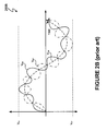
- FIG. 2B depicts a time varying voltage plot 200 B of input signals V IN+ and V IN ⁇ having common mode voltage V CM superimposed on respective differential signals V INS+ and V INS ⁇ .
- the maximum and minimum values of common mode voltage V CM is several times larger than the peak voltages of differential input V INS+ and V INS ⁇ .
- Power must be allocated to accommodate the common mode portion of the input signals to amplifier 102 .
- the common mode voltage can be relatively large, such as ⁇ 10V ⁇ V CM ⁇ +10V and the differential signals V INS+ and V INS ⁇ have voltages that can be relatively small, such as +/ ⁇ 100 millivolts to, for example, +/ ⁇ 2.5 V.
- an apparatus in one embodiment, includes a circuit to generate a floating first supply voltage, wherein during operation of the circuit the first supply voltage tracks a common mode voltage of first and second input signals.
- a method in another embodiment, includes generating a floating first supply voltage that tracks a common mode voltage of first and second input signals. The method further includes providing the first supply voltage to a first circuit.
- an apparatus in a further embodiment, includes a common mode voltage detector to detect a common mode voltage of first and second input signals.
- the apparatus further includes a floating supply voltage generator to generate a first floating supply voltage and a second floating supply voltage, wherein the first and second floating supply voltages track the common mode voltage and the first floating supply voltage and second floating supply voltage are equivalent polar opposites.
- the apparatus also includes a first amplifier configured to receive the first and second floating supply voltages and to amplify the first input signal to generate a first amplified input signal.
- the apparatus additionally includes a second amplifier configured to receive the first and second floating supply voltages and to amplify the second input signal to generate a second amplified input signal and an analog-to-digital converter to convert a difference between the first and second amplified input signals into a digital signal.
- a second amplifier configured to receive the first and second floating supply voltages and to amplify the second input signal to generate a second amplified input signal and an analog-to-digital converter to convert a difference between the first and second amplified input signals into a digital signal.
- FIG. 1 (labeled prior art) depicts an electronic system with an amplifier operating from fixed supply voltages.
- FIGS. 2A and 2B depict a relationship between the fixed supply voltages and the common mode voltage affected input signals to the electronic system of FIG. 1 .
- FIG. 3 depicts an electronic system having floating supply voltages.
- FIG. 4 depicts an embodiment of the electronic system of FIG. 3 .
- FIG. 5 depicts timing signals for a switched capacitor network of the electronic system of FIG. 4 .
- FIGS. 6 and 7 depict a tracking relationship between the floating supply voltages of the electronic system of FIG. 4 and different common mode voltages.
- FIG. 8 depicts a tracking relationship between the floating supply voltages of the electronic system of FIG. 4 and a time-varying common mode voltage.
- FIG. 9 depicts a floating power supply generator for the electronic system of FIG. 3 .
- an electronic system generates at least one floating supply voltage, wherein during operation of the circuit the floating supply voltage tracks a common mode voltage of first and second input signals.
- the floating supply voltage adjusts as the common mode voltage changes.
- the floating supply voltages can be based upon the peak-to-peak values of the first and second output signals without factoring in the common mode voltage.
- the common mode voltage can be rejected without allocating power to process the common mode voltage.
- power levels are established based on the signal portion of the input signals and not by the common mode voltage.
- the input signals are sampled differentially prior to subsequent processing by an analog-to-digital converter so that the common mode signal is not digitized.
- the voltage rails of the floating supply voltage are approximately equal to one-half of the maximum peak-to-peak value of the first and second output signals regardless of the value of the common mode voltage.
- the electronic system generates positive and negative floating supply voltages that track the common mode voltage of the first and second input signals and provides the floating supply voltages to at least one amplifier, such as a differential amplifier.
- the electronic system detects the common mode voltage of the first and second input signals and generates each floating supply voltage using a power transfer circuit referenced to the common mode voltage.
- One or more amplifiers operate from the floating supply voltages and receive the first and second input signals.
- the floating supply voltages track the common mode voltage.
- two amplifiers each generate a respective output signal that tracks the input signal to the respective amplifier.
- An analog-to-digital converter (ADC) converts a difference between the output signals into a digital signal.
- the ADC and the amplifiers can operate from lower supply voltages that are substantially independent from the common mode voltage of the input signals. By operating from lower supply voltages, such as +/ ⁇ 2.5 V (i.e.
- standard, high quality components can be used in place of higher voltage, lower quality components.
- the electronic system can efficiently provide common mode range enhancement by, for example, operating devices using supply voltages that are less than the largest common mode voltage plus maximum peak-to-peak signal voltage.
- the ADC includes a switched capacitor network to alternately couple the input signals to respective sampling capacitors and alternatively couple the sampling capacitors to a second circuit to, for example, complete the analog-to-digital conversion of the input signals.
- the switched capacitor network substantially translates the common mode voltage of the input signals to a lower common mode voltage of the ADC.
- FIG. 3 depicts an electronic system 300 that includes floating supply voltage generator 302 to generate floating supply voltages V FLOAT+ and V FLOAT ⁇ that track a common mode voltage V CM of input signals V IN+ and V IN ⁇ .
- the common mode voltage V CM can be generated in any number of ways, such as inducement by electrostatic and/or electromagnetic sources in the vicinity of conductors connected to input nodes 312 and 314 of respective amplifiers 304 and 306 .
- Exemplary conductors are cables 108 and 109 ( FIG. 1 ).
- Electronic system 300 receives input signals V IN+ and V IN ⁇ .
- the input signals V IN+ and V IN ⁇ can be generated by any source, such as signal source 103 ( FIG. 1 ).
- the input signals V IN+ and V IN ⁇ include respective differential signals V INS+ and V INS ⁇ that are generated by a sensor that senses seismic activity in, for example, oil and gas exploration operations.
- V INS+ and V INS ⁇ are not differential signals.
- the input signal V IN+ V CM +V INS+
- the input signal V IN ⁇ V CM +V INS ⁇ .
- Amplifiers 304 and 306 receive respective input signals V IN+ and V IN ⁇ .
- Amplifiers 304 and 306 each receive and operate from floating supply voltages V FLOAT+ and V FLOAT ⁇ .
- a common mode voltage detector 308 detects the common mode voltage V CM of input signals V IN+ and V IN ⁇ .
- the floating supply voltage generator 302 generates floating supply voltages V FLOAT ⁇ and V FLOAT ⁇ to track the common mode voltage V CM .
- the floating supply voltages V FLOAT ⁇ and V FLOAT ⁇ are generated relative to the common mode voltage V CM .
- the floating supply voltage generator 302 also generates a fixed voltage V DD .
- the fixed voltage V DD can be set so that voltage V DD is greater than or equal to (maxV OUT — PP )/2 but less than [(maxV OUT — PP )/2+maxV CM ].
- “maxV OUT — PP ” represents the maximum peak-to-peak voltage of output signals V OUT+ and V OUT ⁇ .
- V DD can be set so that voltage V DD is greater than or equal to (maxV IN — PP )/2.
- maximumV IN — PP represents the maximum peak-to-peak voltage of output signals V IN+ and V IN ⁇ .
- floating supply voltages V FLOAT+ and V FLOAT ⁇ are set to provide an operating margin to accommodate full-swing signal voltages plus operating voltages of components using floating supply voltages V FLOAT+ and V FLOAT ⁇ .
- V M represents the voltage margin that provides a sufficient margin to allow components, such as amplifiers 304 and 306 to operate.
- the voltage margin V M includes, for example, threshold voltages for field effect transistors of amplifiers 304 and 306 .
- floating supply voltage generator 302 The particular implementation of floating supply voltage generator 302 is a matter of design choice.
- a switched capacitor, power transfer circuit transfers power from one set of capacitors to another while using common mode voltage V CM as a reference to generate floating voltages V FLOAT+ and V FLOAT ⁇ .
- FIG. 4 depicts an exemplary power transfer circuit using a switched capacitor network.
- a power transfer circuit utilizes a transformer to transfer power and generate the floating voltages V FLOAT+ and V FLOAT ⁇ .
- FIG. 9 depicts an exemplary transformer-based power transfer circuit. Other circuits, such as a floating battery can also be used.
- Output signals V OUT+ and V OUT ⁇ respectively represent amplified input signals V IN+ and V IN ⁇ .
- “maxV CM ” represents the maximum anticipated value of the common mode voltage V CM .
- the fixed supply voltage V DD can be set so that the voltage value of fixed supply voltage V DD is greater than or equal to (maxV IN — PP )/2 but less than [(maxV IN — PP )/2+maxV CM ].
- “maxV IN — PP ” represents the maximum peak-to-peak voltage of input signals V IN+ and V IN ⁇ .
- fixed supply voltage V DD is equal to maxV OUT — PP /2.
- V FLOAT+ and V FLOAT ⁇ track the common mode voltage V CM .
- amplifiers 304 and 306 use 80% less power.
- V FLOAT+ ⁇ V FLOAT ⁇ (V H+ ⁇ V H ⁇ )
- V FLOAT+ , V FLOAT ⁇ , or both V FLOAT+ and V FLOAT ⁇ is a matter of design choice.
- the floating supply voltage is useful for virtually any circuit whose supply voltage is conventionally set to account for common mode voltage levels plus input signal voltage levels.
- Amplifiers 304 and 306 generate respective output signals V OUT+ and V OUT ⁇ .
- Signal processor 310 receives output signals V OUT+ and V OUT ⁇ and processes output signals V OUT+ and V OUT ⁇ to generate output signal y(n).
- signal processor 310 is an ADC.
- FIG. 4 depicts electronic system 400 , which represents one embodiment of electronic system 300 .
- Electronic system 400 includes a floating supply voltage generator 402 , which represents one embodiment of floating supply voltage generator 302 .
- the floating supply voltage generator 402 generates floating supply voltages V FLOAT+ and V FLOAT ⁇ to track the common mode voltage V CM of input signals V IN+ and V IN ⁇ .
- Common mode voltage detector 404 which represents one embodiment of common mode voltage detector 308 , includes resistors 406 and 408 .
- the voltage at the junction of resistors 406 and 408 represents the common mode voltage V CM .
- V CM (V IN+ +V IN ⁇ )/2.
- resistance R is a matter of design choice and is, for example, 1 Mohm.
- the non-inverting input terminal of operational amplifier 409 receives the common mode voltage V CM .
- Operational amplifier 409 is configured to provide unity gain so that the output of operational amplifier 409 is the common mode voltage V CM .
- Operational amplifier 409 operates from fixed supply voltages V H+ and V H ⁇ .
- supply voltages V H+ and V H ⁇ are respectively equal to [(V OUT — PP +/2)+maxV CM ] and ⁇ [(V OUT — PP +/2)+maxV CM ].
- maxV CM is 10V
- V OUT — PP is 5V
- V H+ 12.5V
- V H ⁇ ⁇ 12.5V.
- Operational amplifier 409 draws very little current.
- the supply voltages V H ⁇ and V H ⁇ are relatively large compared to the peak-to-peak voltage levels of input signals V IN+ and V IN ⁇ , operational amplifier 409 dissipates very little power.
- operational amplifier 409 can be a simple design.
- operational amplifiers 442 and 444 are internal components of a CS3301A or CS3302A programmable gain amplifier available from Cirrus Logic, Inc. of Austin, Tex.
- the floating supply voltage generator 402 is a power transfer circuit that transfers power from fixed voltage supply 411 to power storage circuits.
- the power storage circuits are capacitors 424 and 430 .
- the floating supply voltage generator 402 includes a V FLOAT controller 410 that operates switches 418 and 420 .
- V FLOAT controller 410 operates switches 418 and 420 so that capacitor 422 alternatively charges to voltage V DD —GND and transfers the charge to capacitor 424 .
- the floating supply voltage generator 402 receives the common mode voltage V CM as a reference voltage.
- Capacitor 424 is referenced on one node to the common mode voltage V CM and on the other node to node 426 .
- V FLOAT controller 410 operates switches 418 and 420 to transfer charge from capacitor 422 to capacitor 424 at a rate sufficient to maintain node 426 at floating supply voltage V FLOAT ⁇ .
- the switching frequency of switches 418 and 420 is a matter of design choice and depends upon, for example, the size of capacitors 422 and 424 , the current demand of devices supplied with power from floating supply voltage generator 402 , the value of floating supply voltage V FLOAT+ , and the amount of ripple voltage on floating supply voltage V FLOAT+ .
- the switching frequency of switches 418 and 420 can be fixed or variable. Exemplary values of capacitors 422 and 428 is 1 ⁇ F or smaller, and an exemplary value of capacitors 424 and 430 is 10 ⁇ F.
- floating supply voltage V FLOAT+ tracks the common mode voltage V CM .
- the floating supply voltage generator 402 also includes V FLOAT controller 412 .
- V FLOAT controller 412 operates in the same manner as V FLOAT controller 410 to transfer power from capacitor 428 to 430 .
- V FLOAT controller 412 operates switch 432 between node 436 at voltage V DD and node 438 at V CM and operates switch 434 between the GND node and node 440 at V FLOAT ⁇ .
- floating supply voltage V FLOAT ⁇ also tracks the common mode voltage V CM .
- Electronic system 400 also includes amplifiers 442 and 444 .
- amplifiers 442 and 444 are depicted individually, amplifiers 442 and 444 can be part of a dual input, dual output amplifier 445 .
- Amplifiers 442 and 444 operate from floating supply voltages V FLOAT ⁇ and V FLOAT ⁇ . Thus, regardless of the value of common mode voltage V CM , amplifiers 442 and 444 are able to process respective input signals V IN+ and V IN ⁇ without clipping the output signals V OUT+ and V OUT ⁇ .
- the gain of amplifiers 442 and 444 is a matter of design choice and is the overall gain of the amplifiers 442 and 444 established by the values of resistors 446 , 447 , and 450 .
- a switched capacitor network 449 of ADC 448 receives output signals V OUT+ and V OUT ⁇ .
- the switched capacitor network 449 transfers a charge proportion to the difference signal (V OUT+ ) ⁇ (V OUT ⁇ ) to node 451 of ADC signal processor 452 and transfers a charge proportional to the difference signal (V OUT ⁇ ) ⁇ (V OUT+ ) to node 454 of ADC in accordance with timing signals ⁇ 1 , ⁇ 1D , ⁇ 2 , and ⁇ 2D .
- Timing signals ⁇ 1 , ⁇ 1D , ⁇ 2 , and ⁇ 2D control the conductivity of switches 456 - 470 in accordance with Table 1:
- ADC 448 is, for example, a 24-bit geophysical, single/dual-channel delta-sigma modulators part number CS5371A or CS5372A available from Cirrus Logic, Inc. of Austin, Tex.
- the particular frequency of timing signals timing signals ⁇ 1 , ⁇ 1D , ⁇ 2 , and ⁇ 2D is a matter of design choice and depends upon, for example, a desired sample rate of output signals V OUT+ and V OUT ⁇ .
- FIG. 5 depicts an exemplary embodiment of timing signals ⁇ 1 , ⁇ 1D , ⁇ 2 , and 2D 500 .
- switches 456 - 470 conduct when the timing signal controlling the respective switch is ‘high’, and switches 456 - 470 are nonconductive when the timing signal controlling the respective switch is ‘low’.
- capacitors 472 and 474 when timing signals ⁇ 1 and ⁇ 1D are high, capacitors 472 and 474 respectively charge to (V CM (ADC) ⁇ V OUT+ ) and (V CM (ADC) ⁇ V OUT ⁇ ).
- the voltage at node 476 is set to the common mode voltage (“V CM (ADC)”) of the ADC 448 , which is often V DD /2.
- V CM (ADC) common mode voltage
- the bandgap reference 480 provides proper scaling of the digital output signal y(n) from ADC 448 .
- Digital Input/Output (I/O) 482 connects the digital output signal y(n) to downstream components (not shown).
- ADC signal processor 452 , bandgap reference 480 , and digital I/O 482 operate from supply voltage V DD and a ground reference GND.
- ADC signal processor 452 , bandgap reference 480 , and/or digital I/O 482 operate from supply voltages V DD+ and V DD ⁇ .
- FIGS. 6 and 7 depict two embodiments of input signals V IN+ and V IN ⁇ relative to common mode voltage V CM and floating supply voltages V FLOAT+ and V FLOAT ⁇ for unity gain amplifiers 442 and 444 .
- the common mode voltage V CM is positive for plot 600 and negative for plot 700 .
- a comparison of signal plot 600 to signal plot 700 of FIGS. 6 and 7 depicts a tracking relationship between the floating supply voltages V FLOAT+ and V FLOAT ⁇ of electronic system 400 and different common mode voltages V CM .
- FIG. 8 depicts a tracking relationship between the floating supply voltages V FLOAT+ and V FLOAT ⁇ of the electronic system 400 and a time-varying common mode voltage V CM .
- the differential signals V INS+ and V INS ⁇ are superimposed on the time-varying common mode voltage V CM , and the floating supply voltages V FLOAT+ and V FLOAT ⁇ track the common mode voltage V CM .
- FIG. 9 depicts a supply voltage generator 900 , which represents one embodiment of floating supply voltage generator 302 .
- Supply voltage generator 900 is a power transfer circuit that receives an alternating current (AC) voltage V AC on a primary coil 902 of 1:N transformer 904 .
- N represents the ratio of turns of primary coil 902 to turns of secondary coil 906 .
- the voltage V AC can be supplied from any source and, in at least one embodiment, is generated internally from supply voltages V DD+ and V DD ⁇ .
- Transformer 904 includes a center tap 908 at the common mode voltage V CM so that the floating supply voltages V FLOAT+ and V FLOAT ⁇ track the common voltage V CM .
- rectifier 910 The output of transformer 904 is rectified by rectifier 910 to generate floating supply voltages V FLOAT+ and V FLOAT ⁇ across filter capacitor 912 to form a floating supply voltage source.
- rectifier 910 is a full-bridge diode rectifier.
- the capacitance of filter capacitor 912 is a matter of design choice and is, for example, 10 ⁇ F.
- a large common mode voltage is superimposed on relatively small differential signals.
- the electronic system reduces power for an ADC system by generating floating supply voltages that track the common mode voltage and have values sufficient to process the differential signals and differential output signals.
Abstract
Description
| TABLE 1 | |||
| Timing Signal | Switches Controlled | ||
| | 464 and 466 | ||
| Φ1D | 456 and 462 | ||
| Φ2 | 468 and 470 | ||
| Φ2D | 458 and 460 | ||
Claims (27)
Priority Applications (2)
| Application Number | Priority Date | Filing Date | Title |
|---|---|---|---|
| US12/347,155 US7994863B2 (en) | 2008-12-31 | 2008-12-31 | Electronic system having common mode voltage range enhancement |
| EP09180901A EP2204905A1 (en) | 2008-12-31 | 2009-12-29 | Electronic system having common mode voltage range enhancement |
Applications Claiming Priority (1)
| Application Number | Priority Date | Filing Date | Title |
|---|---|---|---|
| US12/347,155 US7994863B2 (en) | 2008-12-31 | 2008-12-31 | Electronic system having common mode voltage range enhancement |
Publications (2)
| Publication Number | Publication Date |
|---|---|
| US20100164631A1 US20100164631A1 (en) | 2010-07-01 |
| US7994863B2 true US7994863B2 (en) | 2011-08-09 |
Family
ID=42061149
Family Applications (1)
| Application Number | Title | Priority Date | Filing Date |
|---|---|---|---|
| US12/347,155 Active 2029-04-08 US7994863B2 (en) | 2008-12-31 | 2008-12-31 | Electronic system having common mode voltage range enhancement |
Country Status (2)
| Country | Link |
|---|---|
| US (1) | US7994863B2 (en) |
| EP (1) | EP2204905A1 (en) |
Cited By (1)
| Publication number | Priority date | Publication date | Assignee | Title |
|---|---|---|---|---|
| US20140203873A1 (en) * | 2013-01-24 | 2014-07-24 | Samsung Electronics Co., Ltd | Signal processing apparatus and method |
Families Citing this family (31)
| Publication number | Priority date | Publication date | Assignee | Title |
|---|---|---|---|---|
| US8018171B1 (en) | 2007-03-12 | 2011-09-13 | Cirrus Logic, Inc. | Multi-function duty cycle modifier |
| US7852017B1 (en) | 2007-03-12 | 2010-12-14 | Cirrus Logic, Inc. | Ballast for light emitting diode light sources |
| US7667408B2 (en) | 2007-03-12 | 2010-02-23 | Cirrus Logic, Inc. | Lighting system with lighting dimmer output mapping |
| US8076920B1 (en) | 2007-03-12 | 2011-12-13 | Cirrus Logic, Inc. | Switching power converter and control system |
| US7554473B2 (en) | 2007-05-02 | 2009-06-30 | Cirrus Logic, Inc. | Control system using a nonlinear delta-sigma modulator with nonlinear process modeling |
| US8102127B2 (en) | 2007-06-24 | 2012-01-24 | Cirrus Logic, Inc. | Hybrid gas discharge lamp-LED lighting system |
| WO2009080027A1 (en) * | 2007-12-21 | 2009-07-02 | The Tc Group A/S | Two-channel amplifier with common signal |
| US8576589B2 (en) | 2008-01-30 | 2013-11-05 | Cirrus Logic, Inc. | Switch state controller with a sense current generated operating voltage |
| US8008898B2 (en) | 2008-01-30 | 2011-08-30 | Cirrus Logic, Inc. | Switching regulator with boosted auxiliary winding supply |
| US8022683B2 (en) | 2008-01-30 | 2011-09-20 | Cirrus Logic, Inc. | Powering a power supply integrated circuit with sense current |
| US8279628B2 (en) | 2008-07-25 | 2012-10-02 | Cirrus Logic, Inc. | Audible noise suppression in a resonant switching power converter |
| US8344707B2 (en) | 2008-07-25 | 2013-01-01 | Cirrus Logic, Inc. | Current sensing in a switching power converter |
| US8487546B2 (en) | 2008-08-29 | 2013-07-16 | Cirrus Logic, Inc. | LED lighting system with accurate current control |
| US8179110B2 (en) | 2008-09-30 | 2012-05-15 | Cirrus Logic Inc. | Adjustable constant current source with continuous conduction mode (“CCM”) and discontinuous conduction mode (“DCM”) operation |
| US8222872B1 (en) | 2008-09-30 | 2012-07-17 | Cirrus Logic, Inc. | Switching power converter with selectable mode auxiliary power supply |
| US8288954B2 (en) | 2008-12-07 | 2012-10-16 | Cirrus Logic, Inc. | Primary-side based control of secondary-side current for a transformer |
| US8362707B2 (en) | 2008-12-12 | 2013-01-29 | Cirrus Logic, Inc. | Light emitting diode based lighting system with time division ambient light feedback response |
| US8299722B2 (en) | 2008-12-12 | 2012-10-30 | Cirrus Logic, Inc. | Time division light output sensing and brightness adjustment for different spectra of light emitting diodes |
| US7994863B2 (en) | 2008-12-31 | 2011-08-09 | Cirrus Logic, Inc. | Electronic system having common mode voltage range enhancement |
| US8482223B2 (en) | 2009-04-30 | 2013-07-09 | Cirrus Logic, Inc. | Calibration of lamps |
| US8212493B2 (en) | 2009-06-30 | 2012-07-03 | Cirrus Logic, Inc. | Low energy transfer mode for auxiliary power supply operation in a cascaded switching power converter |
| US8198874B2 (en) | 2009-06-30 | 2012-06-12 | Cirrus Logic, Inc. | Switching power converter with current sensing transformer auxiliary power supply |
| US8643340B1 (en) | 2009-09-29 | 2014-02-04 | Cirrus Logic, Inc. | Powering a circuit by alternating power supply connections in series and parallel with a storage capacitor |
| US9178415B1 (en) | 2009-10-15 | 2015-11-03 | Cirrus Logic, Inc. | Inductor over-current protection using a volt-second value representing an input voltage to a switching power converter |
| US8536799B1 (en) | 2010-07-30 | 2013-09-17 | Cirrus Logic, Inc. | Dimmer detection |
| US8569972B2 (en) | 2010-08-17 | 2013-10-29 | Cirrus Logic, Inc. | Dimmer output emulation |
| JP6334561B2 (en) * | 2012-12-28 | 2018-05-30 | ボルケーノ コーポレイション | Intravascular ultrasound imaging device, interface architecture, and manufacturing method |
| US20140210482A1 (en) * | 2013-01-28 | 2014-07-31 | Qualcomm Incorporated | Method and apparatus for reducing common mode variations in a voltage sensing component |
| US10320346B2 (en) | 2017-08-23 | 2019-06-11 | Semiconductor Components Industries, Llc | Bidirectional current sense amplifier |
| US11108367B2 (en) * | 2019-02-04 | 2021-08-31 | Semiconductor Components Industries, Llc | Internal power supply for amplifiers |
| EP4278434A1 (en) * | 2021-03-15 | 2023-11-22 | Semiconductor Components Industries, LLC | Precision operational amplifier with a floating input stage |
Citations (210)
| Publication number | Priority date | Publication date | Assignee | Title |
|---|---|---|---|---|
| US3316495A (en) | 1964-07-06 | 1967-04-25 | Cons Systems Corp | Low-level commutator with means for providing common mode rejection |
| US3423689A (en) | 1965-08-19 | 1969-01-21 | Hewlett Packard Co | Direct current amplifier |
| US3586988A (en) | 1967-12-01 | 1971-06-22 | Newport Lab | Direct coupled differential amplifier |
| US3725804A (en) | 1971-11-26 | 1973-04-03 | Avco Corp | Capacitance compensation circuit for differential amplifier |
| US3790878A (en) | 1971-12-22 | 1974-02-05 | Keithley Instruments | Switching regulator having improved control circuiting |
| US3881167A (en) | 1973-07-05 | 1975-04-29 | Pelton Company Inc | Method and apparatus to maintain constant phase between reference and output signals |
| US4075701A (en) | 1975-02-12 | 1978-02-21 | Messerschmitt-Bolkow-Blohm Gesellschaft Mit Beschrankter Haftung | Method and circuit arrangement for adapting the measuring range of a measuring device operating with delta modulation in a navigation system |
| GB2069269A (en) | 1980-02-11 | 1981-08-19 | Tektronix Inc | Supply voltage driver |
| US4334250A (en) | 1978-03-16 | 1982-06-08 | Tektronix, Inc. | MFM data encoder with write precompensation |
| US4414493A (en) | 1981-10-06 | 1983-11-08 | Thomas Industries Inc. | Light dimmer for solid state ballast |
| US4476706A (en) | 1982-01-18 | 1984-10-16 | Delphian Partners | Remote calibration system |
| US4677366A (en) | 1986-05-12 | 1987-06-30 | Pioneer Research, Inc. | Unity power factor power supply |
| US4683529A (en) | 1986-11-12 | 1987-07-28 | Zytec Corporation | Switching power supply with automatic power factor correction |
| US4700188A (en) | 1985-01-29 | 1987-10-13 | Micronic Interface Technologies | Electric power measurement system and hall effect based electric power meter for use therein |
| US4737658A (en) | 1985-08-05 | 1988-04-12 | Brown, Boveri & Cie Ag | Centralized control receiver |
| US4797633A (en) | 1987-03-20 | 1989-01-10 | Video Sound, Inc. | Audio amplifier |
| US4937728A (en) | 1989-03-07 | 1990-06-26 | Rca Licensing Corporation | Switch-mode power supply with burst mode standby operation |
| US4940929A (en) | 1989-06-23 | 1990-07-10 | Apollo Computer, Inc. | AC to DC converter with unity power factor |
| US4973919A (en) | 1989-03-23 | 1990-11-27 | Doble Engineering Company | Amplifying with directly coupled, cascaded amplifiers |
| US4979087A (en) | 1988-09-09 | 1990-12-18 | Aviation Limited | Inductive coupler |
| US4980898A (en) | 1989-08-08 | 1990-12-25 | Siemens-Pacesetter, Inc. | Self-oscillating burst mode transmitter with integral number of periods |
| US4992919A (en) | 1989-12-29 | 1991-02-12 | Lee Chu Quon | Parallel resonant converter with zero voltage switching |
| US4994952A (en) | 1988-02-10 | 1991-02-19 | Electronics Research Group, Inc. | Low-noise switching power supply having variable reluctance transformer |
| US5001620A (en) | 1988-07-25 | 1991-03-19 | Astec International Limited | Power factor improvement |
| US5109185A (en) | 1989-09-29 | 1992-04-28 | Ball Newton E | Phase-controlled reversible power converter presenting a controllable counter emf to a source of an impressed voltage |
| US5121079A (en) * | 1991-02-12 | 1992-06-09 | Dargatz Marvin R | Driven-common electronic amplifier |
| US5206540A (en) | 1991-05-09 | 1993-04-27 | Unitrode Corporation | Transformer isolated drive circuit |
| US5264780A (en) | 1992-08-10 | 1993-11-23 | International Business Machines Corporation | On time control and gain circuit |
| US5278490A (en) | 1990-09-04 | 1994-01-11 | California Institute Of Technology | One-cycle controlled switching circuit |
| EP0585789A1 (en) | 1992-09-01 | 1994-03-09 | Power Integrations, Inc. | Three-terminal switched mode power supply integrated circuit |
| US5323157A (en) | 1993-01-15 | 1994-06-21 | Motorola, Inc. | Sigma-delta digital-to-analog converter with reduced noise |
| US5359180A (en) | 1992-10-02 | 1994-10-25 | General Electric Company | Power supply system for arcjet thrusters |
| US5383109A (en) | 1993-12-10 | 1995-01-17 | University Of Colorado | High power factor boost rectifier apparatus |
| US5424932A (en) | 1993-01-05 | 1995-06-13 | Yokogawa Electric Corporation | Multi-output switching power supply having an improved secondary output circuit |
| US5477481A (en) | 1991-02-15 | 1995-12-19 | Crystal Semiconductor Corporation | Switched-capacitor integrator with chopper stabilization performed at the sampling rate |
| US5479333A (en) | 1994-04-25 | 1995-12-26 | Chrysler Corporation | Power supply start up booster circuit |
| US5481178A (en) | 1993-03-23 | 1996-01-02 | Linear Technology Corporation | Control circuit and method for maintaining high efficiency over broad current ranges in a switching regulator circuit |
| US5565761A (en) | 1994-09-02 | 1996-10-15 | Micro Linear Corp | Synchronous switching cascade connected offline PFC-PWM combination power converter controller |
| US5589759A (en) | 1992-07-30 | 1996-12-31 | Sgs-Thomson Microelectronics S.R.L. | Circuit for detecting voltage variations in relation to a set value, for devices comprising error amplifiers |
| US5638265A (en) | 1993-08-24 | 1997-06-10 | Gabor; George | Low line harmonic AC to DC power supply |
| US5691890A (en) | 1995-12-01 | 1997-11-25 | International Business Machines Corporation | Power supply with power factor correction circuit |
| US5747977A (en) | 1995-03-30 | 1998-05-05 | Micro Linear Corporation | Switching regulator having low power mode responsive to load power consumption |
| US5757635A (en) | 1995-12-28 | 1998-05-26 | Samsung Electronics Co., Ltd. | Power factor correction circuit and circuit therefor having sense-FET and boost converter control circuit |
| US5764039A (en) | 1995-11-15 | 1998-06-09 | Samsung Electronics Co., Ltd. | Power factor correction circuit having indirect input voltage sensing |
| US5781040A (en) | 1996-10-31 | 1998-07-14 | Hewlett-Packard Company | Transformer isolated driver for power transistor using frequency switching as the control signal |
| US5783909A (en) | 1997-01-10 | 1998-07-21 | Relume Corporation | Maintaining LED luminous intensity |
| US5798635A (en) | 1996-06-20 | 1998-08-25 | Micro Linear Corporation | One pin error amplifier and switched soft-start for an eight pin PFC-PWM combination integrated circuit converter controller |
| EP0910168A1 (en) | 1997-10-16 | 1999-04-21 | Hewlett-Packard Company | Delta-sigma pulse width modulator |
| US5900683A (en) | 1997-12-23 | 1999-05-04 | Ford Global Technologies, Inc. | Isolated gate driver for power switching device and method for carrying out same |
| US5929400A (en) | 1997-12-22 | 1999-07-27 | Otis Elevator Company | Self commissioning controller for field-oriented elevator motor/drive system |
| US5946206A (en) | 1997-02-17 | 1999-08-31 | Tdk Corporation | Plural parallel resonant switching power supplies |
| US5946202A (en) | 1997-01-24 | 1999-08-31 | Baker Hughes Incorporated | Boost mode power conversion |
| US5952849A (en) | 1997-02-21 | 1999-09-14 | Analog Devices, Inc. | Logic isolator with high transient immunity |
| US5960207A (en) | 1997-01-21 | 1999-09-28 | Dell Usa, L.P. | System and method for reducing power losses by gating an active power factor conversion process |
| US5963086A (en) | 1997-08-08 | 1999-10-05 | Velodyne Acoustics, Inc. | Class D amplifier with switching control |
| US5966297A (en) | 1997-08-28 | 1999-10-12 | Iwatsu Electric Co., Ltd. | Large bandwidth analog isolation circuit |
| US6016038A (en) | 1997-08-26 | 2000-01-18 | Color Kinetics, Inc. | Multicolored LED lighting method and apparatus |
| US6043633A (en) | 1998-06-05 | 2000-03-28 | Systel Development & Industries | Power factor correction method and apparatus |
| US6072969A (en) | 1996-03-05 | 2000-06-06 | Canon Kabushiki Kaisha | Developing cartridge |
| US6084450A (en) | 1997-01-14 | 2000-07-04 | The Regents Of The University Of California | PWM controller with one cycle response |
| US6083276A (en) | 1998-06-11 | 2000-07-04 | Corel, Inc. | Creating and configuring component-based applications using a text-based descriptive attribute grammar |
| US6181114B1 (en) | 1999-10-26 | 2001-01-30 | International Business Machines Corporation | Boost circuit which includes an additional winding for providing an auxiliary output voltage |
| WO2001015316A1 (en) | 1999-08-23 | 2001-03-01 | Intel Corporation | Method and apparatus for matching common mode output voltage at a switched-capacitor to continuous-time interface |
| US6211627B1 (en) | 1997-07-29 | 2001-04-03 | Michael Callahan | Lighting systems |
| US6211626B1 (en) | 1997-08-26 | 2001-04-03 | Color Kinetics, Incorporated | Illumination components |
| US6229292B1 (en) | 1999-02-12 | 2001-05-08 | Analog Devices, Inc. | Voltage regulator compensation circuit and method |
| US6229271B1 (en) | 2000-02-24 | 2001-05-08 | Osram Sylvania Inc. | Low distortion line dimmer and dimming ballast |
| US6246183B1 (en) | 2000-02-28 | 2001-06-12 | Litton Systems, Inc. | Dimmable electrodeless light source |
| US6259614B1 (en) | 1999-07-12 | 2001-07-10 | International Rectifier Corporation | Power factor correction control circuit |
| US6300723B1 (en) | 1998-07-29 | 2001-10-09 | Philips Electronics North America Corporation | Apparatus for power factor control |
| US6304473B1 (en) | 2000-06-02 | 2001-10-16 | Iwatt | Operating a power converter at optimal efficiency |
| US6343026B1 (en) | 2000-11-09 | 2002-01-29 | Artesyn Technologies, Inc. | Current limit circuit for interleaved converters |
| US6344811B1 (en) | 1999-03-16 | 2002-02-05 | Audio Logic, Inc. | Power supply compensation for noise shaped, digital amplifiers |
| WO2002015386A2 (en) | 2000-08-14 | 2002-02-21 | K.S. Waves Ltd. | High-efficiency audio power amplifier |
| US6385063B1 (en) | 1998-06-23 | 2002-05-07 | Siemens Aktiengesellschaft | Hybrid filter for an alternating current network |
| EP1213823A2 (en) | 2000-12-04 | 2002-06-12 | Sanken Electric Co., Ltd. | DC-to-DC converter |
| US6407691B1 (en) | 2000-10-18 | 2002-06-18 | Cirrus Logic, Inc. | Providing power, clock, and control signals as a single combined signal across an isolation barrier in an ADC |
| US6441558B1 (en) | 2000-12-07 | 2002-08-27 | Koninklijke Philips Electronics N.V. | White LED luminary light control system |
| US6445600B2 (en) | 1998-07-13 | 2002-09-03 | Ben-Gurion University Of The Negev Research & Development Authority | Modular structure of an apparatus for regulating the harmonics of current drawn from power lines by an electronic load |
| US6452521B1 (en) | 2001-03-14 | 2002-09-17 | Rosemount Inc. | Mapping a delta-sigma converter range to a sensor range |
| US20020145041A1 (en) | 2001-03-16 | 2002-10-10 | Koninklijke Philips Electronics N.V. | RGB LED based light driver using microprocessor controlled AC distributed power system |
| US20020150151A1 (en) | 1997-04-22 | 2002-10-17 | Silicon Laboratories Inc. | Digital isolation system with hybrid circuit in ADC calibration loop |
| US6469484B2 (en) | 2000-12-13 | 2002-10-22 | Semiconductor Components Industries Llc | Power supply circuit and method thereof to detect demagnitization of the power supply |
| US20020166073A1 (en) | 2001-05-02 | 2002-11-07 | Nguyen James Hung | Apparatus and method for adaptively controlling power supplied to a hot-pluggable subsystem |
| WO2002091805A2 (en) | 2001-05-10 | 2002-11-14 | Color Kinetics Incorporated | Systems and methods for synchronizing lighting effects |
| US6495964B1 (en) | 1998-12-18 | 2002-12-17 | Koninklijke Philips Electronics N.V. | LED luminaire with electrically adjusted color balance using photodetector |
| US6509913B2 (en) | 1998-04-30 | 2003-01-21 | Openwave Systems Inc. | Configurable man-machine interface |
| US20030095013A1 (en) | 2000-05-10 | 2003-05-22 | Melanson John L. | Modulation of a digital input signal using a digital signal modulator and signal splitting |
| US6583550B2 (en) | 2000-10-24 | 2003-06-24 | Toyoda Gosei Co., Ltd. | Fluorescent tube with light emitting diodes |
| US20030174520A1 (en) | 2000-10-24 | 2003-09-18 | Igor Bimbaud | Self-oscillating control circuit voltage converter |
| US6628106B1 (en) | 2001-07-30 | 2003-09-30 | University Of Central Florida | Control method and circuit to provide voltage and current regulation for multiphase DC/DC converters |
| US6636003B2 (en) | 2000-09-06 | 2003-10-21 | Spectrum Kinetics | Apparatus and method for adjusting the color temperature of white semiconduct or light emitters |
| US6646848B2 (en) | 2001-01-31 | 2003-11-11 | Matsushita Electric Industrial Co., Ltd. | Switching power supply apparatus |
| US20030223255A1 (en) | 2002-05-31 | 2003-12-04 | Green Power Technologies Ltd. | Method and apparatus for active power factor correction with minimum input current distortion |
| US20040004465A1 (en) | 2002-07-08 | 2004-01-08 | Cogency Semiconductor Inc. | Dual-output direct current voltage converter |
| US6688753B2 (en) | 2001-02-02 | 2004-02-10 | Koninklijke Philips Electronics N.V. | Integrated light source |
| EP1164819B1 (en) | 2000-06-15 | 2004-02-11 | City University of Hong Kong | Dimmable electronic ballast |
| US20040046683A1 (en) | 2001-03-08 | 2004-03-11 | Shindengen Electric Manufacturing Co., Ltd. | DC stabilized power supply |
| US6713974B2 (en) | 2002-01-10 | 2004-03-30 | Lightech Electronic Industries Ltd. | Lamp transformer for use with an electronic dimmer and method for use thereof for reducing acoustic noise |
| US6724174B1 (en) | 2002-09-12 | 2004-04-20 | Linear Technology Corp. | Adjustable minimum peak inductor current level for burst mode in current-mode DC-DC regulators |
| US6727832B1 (en) | 2002-11-27 | 2004-04-27 | Cirrus Logic, Inc. | Data converters with digitally filtered pulse width modulation output stages and methods and systems using the same |
| US20040085030A1 (en) | 2002-10-30 | 2004-05-06 | Benoit Laflamme | Multicolor lamp system |
| US20040085117A1 (en) | 2000-12-06 | 2004-05-06 | Joachim Melbert | Method and device for switching on and off power semiconductors, especially for the torque-variable operation of an asynchronous machine, for operating an ignition system for spark ignition engines, and switched-mode power supply |
| US6737845B2 (en) | 2001-06-21 | 2004-05-18 | Champion Microelectronic Corp. | Current inrush limiting and bleed resistor current inhibiting in a switching power converter |
| US6741123B1 (en) | 2002-12-26 | 2004-05-25 | Cirrus Logic, Inc. | Delta-sigma amplifiers with output stage supply voltage variation compensation and methods and digital amplifier systems using the same |
| US6753661B2 (en) | 2002-06-17 | 2004-06-22 | Koninklijke Philips Electronics N.V. | LED-based white-light backlighting for electronic displays |
| US6768655B1 (en) | 2003-02-03 | 2004-07-27 | System General Corp. | Discontinuous mode PFC controller having a power saving modulator and operation method thereof |
| US6781351B2 (en) | 2002-08-17 | 2004-08-24 | Supertex Inc. | AC/DC cascaded power converters having high DC conversion ratio and improved AC line harmonics |
| US20040169477A1 (en) | 2003-02-28 | 2004-09-02 | Naoki Yanai | Dimming-control lighting apparatus for incandescent electric lamp |
| US6788011B2 (en) | 1997-08-26 | 2004-09-07 | Color Kinetics, Incorporated | Multicolored LED lighting method and apparatus |
| US20040228116A1 (en) | 2003-05-13 | 2004-11-18 | Carroll Miller | Electroluminescent illumination for a magnetic compass |
| US20040227571A1 (en) | 2003-05-12 | 2004-11-18 | Yasuji Kuribayashi | Power amplifier circuit |
| US20040232971A1 (en) | 2003-03-06 | 2004-11-25 | Denso Corporation | Electrically insulated switching element drive circuit |
| US20040239262A1 (en) | 2002-05-28 | 2004-12-02 | Shigeru Ido | Electronic ballast for a discharge lamp |
| US6839247B1 (en) | 2003-07-10 | 2005-01-04 | System General Corp. | PFC-PWM controller having a power saving means |
| US6860628B2 (en) | 2002-07-17 | 2005-03-01 | Jonas J. Robertson | LED replacement for fluorescent lighting |
| US20050057237A1 (en) | 2002-01-11 | 2005-03-17 | Robert Clavel | Power factor controller |
| US6870325B2 (en) | 2002-02-22 | 2005-03-22 | Oxley Developments Company Limited | Led drive circuit and method |
| US6873065B2 (en) | 1997-10-23 | 2005-03-29 | Analog Devices, Inc. | Non-optical signal isolator |
| US6882552B2 (en) | 2000-06-02 | 2005-04-19 | Iwatt, Inc. | Power converter driven by power pulse and sense pulse |
| US6888322B2 (en) | 1997-08-26 | 2005-05-03 | Color Kinetics Incorporated | Systems and methods for color changing device and enclosure |
| EP1528785A1 (en) | 2003-10-14 | 2005-05-04 | Archimede Elettronica S.r.l. | Device and method for controlling the color of a light source |
| US6894471B2 (en) | 2002-05-31 | 2005-05-17 | St Microelectronics S.R.L. | Method of regulating the supply voltage of a load and related voltage regulator |
| US20050156770A1 (en) | 2004-01-16 | 2005-07-21 | Melanson John L. | Jointly nonlinear delta sigma modulators |
| US20050168492A1 (en) | 2002-05-28 | 2005-08-04 | Koninklijke Philips Electronics N.V. | Motion blur decrease in varying duty cycle |
| US6933706B2 (en) | 2003-09-15 | 2005-08-23 | Semiconductor Components Industries, Llc | Method and circuit for optimizing power efficiency in a DC-DC converter |
| US20050184895A1 (en) | 2004-02-25 | 2005-08-25 | Nellcor Puritan Bennett Inc. | Multi-bit ADC with sigma-delta modulation |
| US6940733B2 (en) | 2002-08-22 | 2005-09-06 | Supertex, Inc. | Optimal control of wide conversion ratio switching converters |
| US6944034B1 (en) | 2003-06-30 | 2005-09-13 | Iwatt Inc. | System and method for input current shaping in a power converter |
| US20050207190A1 (en) | 2004-03-22 | 2005-09-22 | Gritter David J | Power system having a phase locked loop with a notch filter |
| US20050218838A1 (en) | 2004-03-15 | 2005-10-06 | Color Kinetics Incorporated | LED-based lighting network power control methods and apparatus |
| US6956750B1 (en) | 2003-05-16 | 2005-10-18 | Iwatt Inc. | Power converter controller having event generator for detection of events and generation of digital error |
| US6958920B2 (en) | 2003-10-02 | 2005-10-25 | Supertex, Inc. | Switching power converter and method of controlling output voltage thereof using predictive sensing of magnetic flux |
| US20050253533A1 (en) | 2002-05-09 | 2005-11-17 | Color Kinetics Incorporated | Dimmable LED-based MR16 lighting apparatus methods |
| US6967448B2 (en) | 1997-08-26 | 2005-11-22 | Color Kinetics, Incorporated | Methods and apparatus for controlling illumination |
| US6970503B1 (en) | 2000-04-21 | 2005-11-29 | National Semiconductor Corporation | Apparatus and method for converting analog signal to pulse-width-modulated signal |
| US20050270813A1 (en) | 2004-06-04 | 2005-12-08 | Wanfeng Zhang | Parallel current mode control |
| US6975079B2 (en) | 1997-08-26 | 2005-12-13 | Color Kinetics Incorporated | Systems and methods for controlling illumination sources |
| US6975523B2 (en) | 2002-10-16 | 2005-12-13 | Samsung Electronics Co., Ltd. | Power supply capable of protecting electric device circuit |
| US20050275354A1 (en) | 2004-06-10 | 2005-12-15 | Hausman Donald F Jr | Apparatus and methods for regulating delivery of electrical energy |
| US20050275386A1 (en) | 2002-06-23 | 2005-12-15 | Powerlynx A/S | Power converter |
| US6980446B2 (en) | 2002-02-08 | 2005-12-27 | Sanken Electric Co., Ltd. | Circuit for starting power source apparatus |
| US20060023002A1 (en) | 2004-08-02 | 2006-02-02 | Oki Electric Industry Co., Ltd. | Color balancing circuit for a display panel |
| US20060022916A1 (en) | 2004-06-14 | 2006-02-02 | Natale Aiello | LED driving device with variable light intensity |
| EP1014563B1 (en) | 1998-12-14 | 2006-03-01 | Alcatel | Amplifier arrangement with voltage gain and reduced power consumption |
| US7034611B2 (en) * | 2004-02-09 | 2006-04-25 | Texas Instruments Inc. | Multistage common mode feedback for improved linearity line drivers |
| US20060125420A1 (en) | 2004-12-06 | 2006-06-15 | Michael Boone | Candle emulation device |
| US7064498B2 (en) | 1997-08-26 | 2006-06-20 | Color Kinetics Incorporated | Light-emitting diode based products |
| US7064531B1 (en) | 2005-03-31 | 2006-06-20 | Micrel, Inc. | PWM buck regulator with LDO standby mode |
| WO2006067521A1 (en) | 2004-12-20 | 2006-06-29 | Outside In (Cambridge) Limited | Lightning apparatus and method |
| US7075329B2 (en) | 2003-04-30 | 2006-07-11 | Analog Devices, Inc. | Signal isolators using micro-transformers |
| US7078963B1 (en) | 2003-03-21 | 2006-07-18 | D2Audio Corporation | Integrated PULSHI mode with shutdown |
| US7088059B2 (en) | 2004-07-21 | 2006-08-08 | Boca Flasher | Modulated control circuit and method for current-limited dimming and color mixing of display and illumination systems |
| US7102902B1 (en) | 2005-02-17 | 2006-09-05 | Ledtronics, Inc. | Dimmer circuit for LED |
| US7106603B1 (en) | 2005-05-23 | 2006-09-12 | Li Shin International Enterprise Corporation | Switch-mode self-coupling auxiliary power device |
| US7109791B1 (en) | 2004-07-09 | 2006-09-19 | Rf Micro Devices, Inc. | Tailored collector voltage to minimize variation in AM to PM distortion in a power amplifier |
| US20060214603A1 (en) | 2005-03-22 | 2006-09-28 | In-Hwan Oh | Single-stage digital power converter for driving LEDs |
| US20060226795A1 (en) | 2005-04-08 | 2006-10-12 | S.C. Johnson & Son, Inc. | Lighting device having a circuit including a plurality of light emitting diodes, and methods of controlling and calibrating lighting devices |
| US7126288B2 (en) | 2003-05-05 | 2006-10-24 | International Rectifier Corporation | Digital electronic ballast control apparatus and method |
| US20060238136A1 (en) | 2003-07-02 | 2006-10-26 | Johnson Iii H F | Lamp and bulb for illumination and ambiance lighting |
| US20060261754A1 (en) | 2005-05-18 | 2006-11-23 | Samsung Electro-Mechanics Co., Ltd. | LED driving circuit having dimming circuit |
| US7145295B1 (en) | 2005-07-24 | 2006-12-05 | Aimtron Technology Corp. | Dimming control circuit for light-emitting diodes |
| US20060285365A1 (en) | 2005-06-16 | 2006-12-21 | Active Semiconductors International Inc. | Primary side constant output current controller |
| WO2006135584A1 (en) | 2005-06-10 | 2006-12-21 | Rf Micro Devices, Inc. | Doherty amplifier configuration for a collector controlled power amplifier |
| US7158633B1 (en) | 1999-11-16 | 2007-01-02 | Silicon Laboratories, Inc. | Method and apparatus for monitoring subscriber loop interface circuitry power dissipation |
| US20070024213A1 (en) | 2005-07-28 | 2007-02-01 | Synditec, Inc. | Pulsed current averaging controller with amplitude modulation and time division multiplexing for arrays of independent pluralities of light emitting diodes |
| US20070029946A1 (en) | 2005-08-03 | 2007-02-08 | Yu Chung-Che | APPARATUS OF LIGHT SOURCE AND ADJUSTABLE CONTROL CIRCUIT FOR LEDs |
| US20070040512A1 (en) | 2005-08-17 | 2007-02-22 | Tir Systems Ltd. | Digitally controlled luminaire system |
| US7183957B1 (en) | 2005-12-30 | 2007-02-27 | Cirrus Logic, Inc. | Signal processing system with analog-to-digital converter using delta-sigma modulation having an internal stabilizer loop |
| US20070053182A1 (en) | 2005-09-07 | 2007-03-08 | Jonas Robertson | Combination fluorescent and LED lighting system |
| US20070103949A1 (en) | 2004-08-27 | 2007-05-10 | Sanken Electric Co., Ltd. | Power factor improving circuit |
| US7221130B2 (en) | 2005-01-05 | 2007-05-22 | Fyrestorm, Inc. | Switching power converter employing pulse frequency modulation control |
| US20070124615A1 (en) | 2005-11-29 | 2007-05-31 | Potentia Semiconductor Corporation | Standby arrangement for power supplies |
| WO2007026170A3 (en) | 2005-09-03 | 2007-06-14 | Light Ltd E | Improvements to lighting systems |
| US7233135B2 (en) | 2003-09-29 | 2007-06-19 | Murata Manufacturing Co., Ltd. | Ripple converter |
| US7246919B2 (en) | 2004-03-03 | 2007-07-24 | S.C. Johnson & Son, Inc. | LED light bulb with active ingredient emission |
| US20070182699A1 (en) | 2006-02-09 | 2007-08-09 | Samsung Electro-Mechanics Co., Ltd. | Field sequential color mode liquid crystal display |
| US7255457B2 (en) | 1999-11-18 | 2007-08-14 | Color Kinetics Incorporated | Methods and apparatus for generating and modulating illumination conditions |
| US7266001B1 (en) | 2004-03-19 | 2007-09-04 | Marvell International Ltd. | Method and apparatus for controlling power factor correction |
| US7288902B1 (en) | 2007-03-12 | 2007-10-30 | Cirrus Logic, Inc. | Color variations in a dimmable lighting device with stable color temperature light sources |
| US7292013B1 (en) | 2004-09-24 | 2007-11-06 | Marvell International Ltd. | Circuits, systems, methods, and software for power factor correction and/or control |
| US7310244B2 (en) | 2006-01-25 | 2007-12-18 | System General Corp. | Primary side controlled switching regulator |
| US20080043504A1 (en) | 2006-08-16 | 2008-02-21 | On-Bright Electronics (Shanghai) Co., Ltd. | System and method for providing control for switch-mode power supply |
| US20080054815A1 (en) | 2006-09-01 | 2008-03-06 | Broadcom Corporation | Single inductor serial-parallel LED driver |
| US7345458B2 (en) | 2003-07-07 | 2008-03-18 | Nippon Telegraph And Telephone Corporation | Booster that utilizes energy output from a power supply unit |
| US20080130322A1 (en) | 2006-12-01 | 2008-06-05 | Artusi Daniel A | Power system with power converters having an adaptive controller |
| US7394210B2 (en) | 2004-09-29 | 2008-07-01 | Tir Technology Lp | System and method for controlling luminaires |
| US20080174291A1 (en) | 2002-04-29 | 2008-07-24 | Emerson Energy Systems Ab | Power Supply System and Apparatus |
| US20080174372A1 (en) | 2007-01-19 | 2008-07-24 | Tucker John C | Multi-stage amplifier with multiple sets of fixed and variable voltage rails |
| US20080175029A1 (en) | 2007-01-18 | 2008-07-24 | Sang-Hwa Jung | Burst mode operation in a DC-DC converter |
| US20080192509A1 (en) | 2007-02-13 | 2008-08-14 | Dhuyvetter Timothy A | Dc-dc converter with isolation |
| US20080232141A1 (en) | 2006-12-01 | 2008-09-25 | Artusi Daniel A | Power System with Power Converters Having an Adaptive Controller |
| US20080239764A1 (en) | 2007-03-30 | 2008-10-02 | Cambridge Semiconductor Limited | Forward power converter controllers |
| US20080259655A1 (en) | 2007-04-19 | 2008-10-23 | Da-Chun Wei | Switching-mode power converter and pulse-width-modulation control circuit with primary-side feedback control |
| US20080278132A1 (en) | 2007-05-07 | 2008-11-13 | Kesterson John W | Digital Compensation For Cable Drop In A Primary Side Control Power Supply Controller |
| US7511437B2 (en) | 2006-02-10 | 2009-03-31 | Philips Solid-State Lighting Solutions, Inc. | Methods and apparatus for high power factor controlled power delivery using a single switching stage per load |
| US7538499B2 (en) | 2005-03-03 | 2009-05-26 | Tir Technology Lp | Method and apparatus for controlling thermal stress in lighting devices |
| US7545130B2 (en) | 2005-11-11 | 2009-06-09 | L&L Engineering, Llc | Non-linear controller for switching power supply |
| US20090147544A1 (en) | 2007-12-11 | 2009-06-11 | Melanson John L | Modulated transformer-coupled gate control signaling method and apparatus |
| US7554473B2 (en) | 2007-05-02 | 2009-06-30 | Cirrus Logic, Inc. | Control system using a nonlinear delta-sigma modulator with nonlinear process modeling |
| US20090174479A1 (en) * | 2008-01-04 | 2009-07-09 | Texas Instruments Incorporated | High-voltage differential amplifier and method using low voltage amplifier and dynamic voltage selection |
| US7569996B2 (en) | 2004-03-19 | 2009-08-04 | Fred H Holmes | Omni voltage direct current power supply |
| US7583136B2 (en) * | 2000-03-28 | 2009-09-01 | International Rectifier Corporation | Active filter for reduction of common mode current |
| US20090218960A1 (en) | 2007-03-13 | 2009-09-03 | Renaissance Lighting, Inc. | Step-wise intensity control of a solid state lighting system |
| US7656103B2 (en) | 2006-01-20 | 2010-02-02 | Exclara, Inc. | Impedance matching circuit for current regulation of solid state lighting |
| US7710047B2 (en) | 2004-09-21 | 2010-05-04 | Exclara, Inc. | System and method for driving LED |
| US7746671B2 (en) | 2005-05-23 | 2010-06-29 | Infineon Technologies Ag | Control circuit for a switch unit of a clocked power supply circuit, and resonance converter |
| US7750738B2 (en) * | 2008-11-20 | 2010-07-06 | Infineon Technologies Ag | Process, voltage and temperature control for high-speed, low-power fixed and variable gain amplifiers based on MOSFET resistors |
| EP2204905A1 (en) | 2008-12-31 | 2010-07-07 | Cirrus Logic, Inc. | Electronic system having common mode voltage range enhancement |
| US7804256B2 (en) | 2007-03-12 | 2010-09-28 | Cirrus Logic, Inc. | Power control system for current regulated light sources |
Family Cites Families (2)
| Publication number | Priority date | Publication date | Assignee | Title |
|---|---|---|---|---|
| US4781040A (en) * | 1986-07-04 | 1988-11-01 | Loyal Kogyo Kabushiki Kaisha | Latch needle for knitting machine |
| JP2555231B2 (en) * | 1991-05-21 | 1996-11-20 | 富士通株式会社 | Method for manufacturing aluminum nitride multilayer circuit board |
-
2008
- 2008-12-31 US US12/347,155 patent/US7994863B2/en active Active
-
2009
- 2009-12-29 EP EP09180901A patent/EP2204905A1/en not_active Withdrawn
Patent Citations (229)
| Publication number | Priority date | Publication date | Assignee | Title |
|---|---|---|---|---|
| US3316495A (en) | 1964-07-06 | 1967-04-25 | Cons Systems Corp | Low-level commutator with means for providing common mode rejection |
| US3423689A (en) | 1965-08-19 | 1969-01-21 | Hewlett Packard Co | Direct current amplifier |
| US3586988A (en) | 1967-12-01 | 1971-06-22 | Newport Lab | Direct coupled differential amplifier |
| US3725804A (en) | 1971-11-26 | 1973-04-03 | Avco Corp | Capacitance compensation circuit for differential amplifier |
| US3790878A (en) | 1971-12-22 | 1974-02-05 | Keithley Instruments | Switching regulator having improved control circuiting |
| US3881167A (en) | 1973-07-05 | 1975-04-29 | Pelton Company Inc | Method and apparatus to maintain constant phase between reference and output signals |
| US4075701A (en) | 1975-02-12 | 1978-02-21 | Messerschmitt-Bolkow-Blohm Gesellschaft Mit Beschrankter Haftung | Method and circuit arrangement for adapting the measuring range of a measuring device operating with delta modulation in a navigation system |
| US4334250A (en) | 1978-03-16 | 1982-06-08 | Tektronix, Inc. | MFM data encoder with write precompensation |
| GB2069269A (en) | 1980-02-11 | 1981-08-19 | Tektronix Inc | Supply voltage driver |
| US4414493A (en) | 1981-10-06 | 1983-11-08 | Thomas Industries Inc. | Light dimmer for solid state ballast |
| US4476706A (en) | 1982-01-18 | 1984-10-16 | Delphian Partners | Remote calibration system |
| US4700188A (en) | 1985-01-29 | 1987-10-13 | Micronic Interface Technologies | Electric power measurement system and hall effect based electric power meter for use therein |
| US4737658A (en) | 1985-08-05 | 1988-04-12 | Brown, Boveri & Cie Ag | Centralized control receiver |
| US4677366A (en) | 1986-05-12 | 1987-06-30 | Pioneer Research, Inc. | Unity power factor power supply |
| US4683529A (en) | 1986-11-12 | 1987-07-28 | Zytec Corporation | Switching power supply with automatic power factor correction |
| US4797633A (en) | 1987-03-20 | 1989-01-10 | Video Sound, Inc. | Audio amplifier |
| US4994952A (en) | 1988-02-10 | 1991-02-19 | Electronics Research Group, Inc. | Low-noise switching power supply having variable reluctance transformer |
| US5001620A (en) | 1988-07-25 | 1991-03-19 | Astec International Limited | Power factor improvement |
| US4979087A (en) | 1988-09-09 | 1990-12-18 | Aviation Limited | Inductive coupler |
| US4937728A (en) | 1989-03-07 | 1990-06-26 | Rca Licensing Corporation | Switch-mode power supply with burst mode standby operation |
| US4973919A (en) | 1989-03-23 | 1990-11-27 | Doble Engineering Company | Amplifying with directly coupled, cascaded amplifiers |
| US4940929A (en) | 1989-06-23 | 1990-07-10 | Apollo Computer, Inc. | AC to DC converter with unity power factor |
| US4980898A (en) | 1989-08-08 | 1990-12-25 | Siemens-Pacesetter, Inc. | Self-oscillating burst mode transmitter with integral number of periods |
| US5109185A (en) | 1989-09-29 | 1992-04-28 | Ball Newton E | Phase-controlled reversible power converter presenting a controllable counter emf to a source of an impressed voltage |
| US4992919A (en) | 1989-12-29 | 1991-02-12 | Lee Chu Quon | Parallel resonant converter with zero voltage switching |
| US5278490A (en) | 1990-09-04 | 1994-01-11 | California Institute Of Technology | One-cycle controlled switching circuit |
| US5121079A (en) * | 1991-02-12 | 1992-06-09 | Dargatz Marvin R | Driven-common electronic amplifier |
| US5477481A (en) | 1991-02-15 | 1995-12-19 | Crystal Semiconductor Corporation | Switched-capacitor integrator with chopper stabilization performed at the sampling rate |
| US5206540A (en) | 1991-05-09 | 1993-04-27 | Unitrode Corporation | Transformer isolated drive circuit |
| US5589759A (en) | 1992-07-30 | 1996-12-31 | Sgs-Thomson Microelectronics S.R.L. | Circuit for detecting voltage variations in relation to a set value, for devices comprising error amplifiers |
| US5264780A (en) | 1992-08-10 | 1993-11-23 | International Business Machines Corporation | On time control and gain circuit |
| EP0585789A1 (en) | 1992-09-01 | 1994-03-09 | Power Integrations, Inc. | Three-terminal switched mode power supply integrated circuit |
| US5359180A (en) | 1992-10-02 | 1994-10-25 | General Electric Company | Power supply system for arcjet thrusters |
| US5424932A (en) | 1993-01-05 | 1995-06-13 | Yokogawa Electric Corporation | Multi-output switching power supply having an improved secondary output circuit |
| US5323157A (en) | 1993-01-15 | 1994-06-21 | Motorola, Inc. | Sigma-delta digital-to-analog converter with reduced noise |
| US5994885A (en) | 1993-03-23 | 1999-11-30 | Linear Technology Corporation | Control circuit and method for maintaining high efficiency over broad current ranges in a switching regulator circuit |
| US5481178A (en) | 1993-03-23 | 1996-01-02 | Linear Technology Corporation | Control circuit and method for maintaining high efficiency over broad current ranges in a switching regulator circuit |
| US6304066B1 (en) | 1993-03-23 | 2001-10-16 | Linear Technology Corporation | Control circuit and method for maintaining high efficiency over broad current ranges in a switching regular circuit |
| US6580258B2 (en) | 1993-03-23 | 2003-06-17 | Linear Technology Corporation | Control circuit and method for maintaining high efficiency over broad current ranges in a switching regulator circuit |
| US5638265A (en) | 1993-08-24 | 1997-06-10 | Gabor; George | Low line harmonic AC to DC power supply |
| US5383109A (en) | 1993-12-10 | 1995-01-17 | University Of Colorado | High power factor boost rectifier apparatus |
| US5479333A (en) | 1994-04-25 | 1995-12-26 | Chrysler Corporation | Power supply start up booster circuit |
| US5565761A (en) | 1994-09-02 | 1996-10-15 | Micro Linear Corp | Synchronous switching cascade connected offline PFC-PWM combination power converter controller |
| US5747977A (en) | 1995-03-30 | 1998-05-05 | Micro Linear Corporation | Switching regulator having low power mode responsive to load power consumption |
| US5764039A (en) | 1995-11-15 | 1998-06-09 | Samsung Electronics Co., Ltd. | Power factor correction circuit having indirect input voltage sensing |
| US5691890A (en) | 1995-12-01 | 1997-11-25 | International Business Machines Corporation | Power supply with power factor correction circuit |
| US5757635A (en) | 1995-12-28 | 1998-05-26 | Samsung Electronics Co., Ltd. | Power factor correction circuit and circuit therefor having sense-FET and boost converter control circuit |
| US6072969A (en) | 1996-03-05 | 2000-06-06 | Canon Kabushiki Kaisha | Developing cartridge |
| US5798635A (en) | 1996-06-20 | 1998-08-25 | Micro Linear Corporation | One pin error amplifier and switched soft-start for an eight pin PFC-PWM combination integrated circuit converter controller |
| US5781040A (en) | 1996-10-31 | 1998-07-14 | Hewlett-Packard Company | Transformer isolated driver for power transistor using frequency switching as the control signal |
| US5783909A (en) | 1997-01-10 | 1998-07-21 | Relume Corporation | Maintaining LED luminous intensity |
| US6084450A (en) | 1997-01-14 | 2000-07-04 | The Regents Of The University Of California | PWM controller with one cycle response |
| US5960207A (en) | 1997-01-21 | 1999-09-28 | Dell Usa, L.P. | System and method for reducing power losses by gating an active power factor conversion process |
| US5946202A (en) | 1997-01-24 | 1999-08-31 | Baker Hughes Incorporated | Boost mode power conversion |
| US5946206A (en) | 1997-02-17 | 1999-08-31 | Tdk Corporation | Plural parallel resonant switching power supplies |
| US5952849A (en) | 1997-02-21 | 1999-09-14 | Analog Devices, Inc. | Logic isolator with high transient immunity |
| US7050509B2 (en) | 1997-04-22 | 2006-05-23 | Silicon Laboratories Inc. | Digital isolation system with hybrid circuit in ADC calibration loop |
| US20020150151A1 (en) | 1997-04-22 | 2002-10-17 | Silicon Laboratories Inc. | Digital isolation system with hybrid circuit in ADC calibration loop |
| US7003023B2 (en) | 1997-04-22 | 2006-02-21 | Silicon Laboratories Inc. | Digital isolation system with ADC offset calibration |
| US6211627B1 (en) | 1997-07-29 | 2001-04-03 | Michael Callahan | Lighting systems |
| US5963086A (en) | 1997-08-08 | 1999-10-05 | Velodyne Acoustics, Inc. | Class D amplifier with switching control |
| US6806659B1 (en) | 1997-08-26 | 2004-10-19 | Color Kinetics, Incorporated | Multicolored LED lighting method and apparatus |
| US6888322B2 (en) | 1997-08-26 | 2005-05-03 | Color Kinetics Incorporated | Systems and methods for color changing device and enclosure |
| US7135824B2 (en) | 1997-08-26 | 2006-11-14 | Color Kinetics Incorporated | Systems and methods for controlling illumination sources |
| US6788011B2 (en) | 1997-08-26 | 2004-09-07 | Color Kinetics, Incorporated | Multicolored LED lighting method and apparatus |
| US6150774A (en) | 1997-08-26 | 2000-11-21 | Color Kinetics, Incorporated | Multicolored LED lighting method and apparatus |
| US6211626B1 (en) | 1997-08-26 | 2001-04-03 | Color Kinetics, Incorporated | Illumination components |
| US7064498B2 (en) | 1997-08-26 | 2006-06-20 | Color Kinetics Incorporated | Light-emitting diode based products |
| US6967448B2 (en) | 1997-08-26 | 2005-11-22 | Color Kinetics, Incorporated | Methods and apparatus for controlling illumination |
| US6975079B2 (en) | 1997-08-26 | 2005-12-13 | Color Kinetics Incorporated | Systems and methods for controlling illumination sources |
| US6016038A (en) | 1997-08-26 | 2000-01-18 | Color Kinetics, Inc. | Multicolored LED lighting method and apparatus |
| US5966297A (en) | 1997-08-28 | 1999-10-12 | Iwatsu Electric Co., Ltd. | Large bandwidth analog isolation circuit |
| EP0910168A1 (en) | 1997-10-16 | 1999-04-21 | Hewlett-Packard Company | Delta-sigma pulse width modulator |
| US6873065B2 (en) | 1997-10-23 | 2005-03-29 | Analog Devices, Inc. | Non-optical signal isolator |
| US5929400A (en) | 1997-12-22 | 1999-07-27 | Otis Elevator Company | Self commissioning controller for field-oriented elevator motor/drive system |
| US5900683A (en) | 1997-12-23 | 1999-05-04 | Ford Global Technologies, Inc. | Isolated gate driver for power switching device and method for carrying out same |
| US6509913B2 (en) | 1998-04-30 | 2003-01-21 | Openwave Systems Inc. | Configurable man-machine interface |
| US6043633A (en) | 1998-06-05 | 2000-03-28 | Systel Development & Industries | Power factor correction method and apparatus |
| US6083276A (en) | 1998-06-11 | 2000-07-04 | Corel, Inc. | Creating and configuring component-based applications using a text-based descriptive attribute grammar |
| US6385063B1 (en) | 1998-06-23 | 2002-05-07 | Siemens Aktiengesellschaft | Hybrid filter for an alternating current network |
| US6445600B2 (en) | 1998-07-13 | 2002-09-03 | Ben-Gurion University Of The Negev Research & Development Authority | Modular structure of an apparatus for regulating the harmonics of current drawn from power lines by an electronic load |
| US6300723B1 (en) | 1998-07-29 | 2001-10-09 | Philips Electronics North America Corporation | Apparatus for power factor control |
| EP1014563B1 (en) | 1998-12-14 | 2006-03-01 | Alcatel | Amplifier arrangement with voltage gain and reduced power consumption |
| US6495964B1 (en) | 1998-12-18 | 2002-12-17 | Koninklijke Philips Electronics N.V. | LED luminaire with electrically adjusted color balance using photodetector |
| US6229292B1 (en) | 1999-02-12 | 2001-05-08 | Analog Devices, Inc. | Voltage regulator compensation circuit and method |
| US6344811B1 (en) | 1999-03-16 | 2002-02-05 | Audio Logic, Inc. | Power supply compensation for noise shaped, digital amplifiers |
| US6259614B1 (en) | 1999-07-12 | 2001-07-10 | International Rectifier Corporation | Power factor correction control circuit |
| WO2001015316A1 (en) | 1999-08-23 | 2001-03-01 | Intel Corporation | Method and apparatus for matching common mode output voltage at a switched-capacitor to continuous-time interface |
| US6181114B1 (en) | 1999-10-26 | 2001-01-30 | International Business Machines Corporation | Boost circuit which includes an additional winding for providing an auxiliary output voltage |
| US7158633B1 (en) | 1999-11-16 | 2007-01-02 | Silicon Laboratories, Inc. | Method and apparatus for monitoring subscriber loop interface circuitry power dissipation |
| US7255457B2 (en) | 1999-11-18 | 2007-08-14 | Color Kinetics Incorporated | Methods and apparatus for generating and modulating illumination conditions |
| US6229271B1 (en) | 2000-02-24 | 2001-05-08 | Osram Sylvania Inc. | Low distortion line dimmer and dimming ballast |
| US6246183B1 (en) | 2000-02-28 | 2001-06-12 | Litton Systems, Inc. | Dimmable electrodeless light source |
| US7583136B2 (en) * | 2000-03-28 | 2009-09-01 | International Rectifier Corporation | Active filter for reduction of common mode current |
| US6970503B1 (en) | 2000-04-21 | 2005-11-29 | National Semiconductor Corporation | Apparatus and method for converting analog signal to pulse-width-modulated signal |
| US20030095013A1 (en) | 2000-05-10 | 2003-05-22 | Melanson John L. | Modulation of a digital input signal using a digital signal modulator and signal splitting |
| US6882552B2 (en) | 2000-06-02 | 2005-04-19 | Iwatt, Inc. | Power converter driven by power pulse and sense pulse |
| US6304473B1 (en) | 2000-06-02 | 2001-10-16 | Iwatt | Operating a power converter at optimal efficiency |
| EP1164819B1 (en) | 2000-06-15 | 2004-02-11 | City University of Hong Kong | Dimmable electronic ballast |
| WO2002015386A2 (en) | 2000-08-14 | 2002-02-21 | K.S. Waves Ltd. | High-efficiency audio power amplifier |
| US6636003B2 (en) | 2000-09-06 | 2003-10-21 | Spectrum Kinetics | Apparatus and method for adjusting the color temperature of white semiconduct or light emitters |
| US6407691B1 (en) | 2000-10-18 | 2002-06-18 | Cirrus Logic, Inc. | Providing power, clock, and control signals as a single combined signal across an isolation barrier in an ADC |
| US6583550B2 (en) | 2000-10-24 | 2003-06-24 | Toyoda Gosei Co., Ltd. | Fluorescent tube with light emitting diodes |
| US6963496B2 (en) | 2000-10-24 | 2005-11-08 | Stmicroelectronics S.A. | Voltage converter with a self-oscillating control circuit |
| US20030174520A1 (en) | 2000-10-24 | 2003-09-18 | Igor Bimbaud | Self-oscillating control circuit voltage converter |
| US6343026B1 (en) | 2000-11-09 | 2002-01-29 | Artesyn Technologies, Inc. | Current limit circuit for interleaved converters |
| EP1213823A2 (en) | 2000-12-04 | 2002-06-12 | Sanken Electric Co., Ltd. | DC-to-DC converter |
| US20040085117A1 (en) | 2000-12-06 | 2004-05-06 | Joachim Melbert | Method and device for switching on and off power semiconductors, especially for the torque-variable operation of an asynchronous machine, for operating an ignition system for spark ignition engines, and switched-mode power supply |
| US6441558B1 (en) | 2000-12-07 | 2002-08-27 | Koninklijke Philips Electronics N.V. | White LED luminary light control system |
| US6469484B2 (en) | 2000-12-13 | 2002-10-22 | Semiconductor Components Industries Llc | Power supply circuit and method thereof to detect demagnitization of the power supply |
| US6646848B2 (en) | 2001-01-31 | 2003-11-11 | Matsushita Electric Industrial Co., Ltd. | Switching power supply apparatus |
| US6688753B2 (en) | 2001-02-02 | 2004-02-10 | Koninklijke Philips Electronics N.V. | Integrated light source |
| US20040046683A1 (en) | 2001-03-08 | 2004-03-11 | Shindengen Electric Manufacturing Co., Ltd. | DC stabilized power supply |
| US6452521B1 (en) | 2001-03-14 | 2002-09-17 | Rosemount Inc. | Mapping a delta-sigma converter range to a sensor range |
| US20020145041A1 (en) | 2001-03-16 | 2002-10-10 | Koninklijke Philips Electronics N.V. | RGB LED based light driver using microprocessor controlled AC distributed power system |
| US20020166073A1 (en) | 2001-05-02 | 2002-11-07 | Nguyen James Hung | Apparatus and method for adaptively controlling power supplied to a hot-pluggable subsystem |
| WO2002091805A2 (en) | 2001-05-10 | 2002-11-14 | Color Kinetics Incorporated | Systems and methods for synchronizing lighting effects |
| US6737845B2 (en) | 2001-06-21 | 2004-05-18 | Champion Microelectronic Corp. | Current inrush limiting and bleed resistor current inhibiting in a switching power converter |
| US6628106B1 (en) | 2001-07-30 | 2003-09-30 | University Of Central Florida | Control method and circuit to provide voltage and current regulation for multiphase DC/DC converters |
| US6713974B2 (en) | 2002-01-10 | 2004-03-30 | Lightech Electronic Industries Ltd. | Lamp transformer for use with an electronic dimmer and method for use thereof for reducing acoustic noise |
| US20050057237A1 (en) | 2002-01-11 | 2005-03-17 | Robert Clavel | Power factor controller |
| US6980446B2 (en) | 2002-02-08 | 2005-12-27 | Sanken Electric Co., Ltd. | Circuit for starting power source apparatus |
| US6870325B2 (en) | 2002-02-22 | 2005-03-22 | Oxley Developments Company Limited | Led drive circuit and method |
| US20080174291A1 (en) | 2002-04-29 | 2008-07-24 | Emerson Energy Systems Ab | Power Supply System and Apparatus |
| US20050253533A1 (en) | 2002-05-09 | 2005-11-17 | Color Kinetics Incorporated | Dimmable LED-based MR16 lighting apparatus methods |
| US20040239262A1 (en) | 2002-05-28 | 2004-12-02 | Shigeru Ido | Electronic ballast for a discharge lamp |
| US20050168492A1 (en) | 2002-05-28 | 2005-08-04 | Koninklijke Philips Electronics N.V. | Motion blur decrease in varying duty cycle |
| US20030223255A1 (en) | 2002-05-31 | 2003-12-04 | Green Power Technologies Ltd. | Method and apparatus for active power factor correction with minimum input current distortion |
| US6894471B2 (en) | 2002-05-31 | 2005-05-17 | St Microelectronics S.R.L. | Method of regulating the supply voltage of a load and related voltage regulator |
| US6753661B2 (en) | 2002-06-17 | 2004-06-22 | Koninklijke Philips Electronics N.V. | LED-based white-light backlighting for electronic displays |
| US20050275386A1 (en) | 2002-06-23 | 2005-12-15 | Powerlynx A/S | Power converter |
| US20040004465A1 (en) | 2002-07-08 | 2004-01-08 | Cogency Semiconductor Inc. | Dual-output direct current voltage converter |
| US6756772B2 (en) | 2002-07-08 | 2004-06-29 | Cogency Semiconductor Inc. | Dual-output direct current voltage converter |
| US6860628B2 (en) | 2002-07-17 | 2005-03-01 | Jonas J. Robertson | LED replacement for fluorescent lighting |
| US6781351B2 (en) | 2002-08-17 | 2004-08-24 | Supertex Inc. | AC/DC cascaded power converters having high DC conversion ratio and improved AC line harmonics |
| US6940733B2 (en) | 2002-08-22 | 2005-09-06 | Supertex, Inc. | Optimal control of wide conversion ratio switching converters |
| US6724174B1 (en) | 2002-09-12 | 2004-04-20 | Linear Technology Corp. | Adjustable minimum peak inductor current level for burst mode in current-mode DC-DC regulators |
| US6975523B2 (en) | 2002-10-16 | 2005-12-13 | Samsung Electronics Co., Ltd. | Power supply capable of protecting electric device circuit |
| US20040085030A1 (en) | 2002-10-30 | 2004-05-06 | Benoit Laflamme | Multicolor lamp system |
| US6727832B1 (en) | 2002-11-27 | 2004-04-27 | Cirrus Logic, Inc. | Data converters with digitally filtered pulse width modulation output stages and methods and systems using the same |
| US6741123B1 (en) | 2002-12-26 | 2004-05-25 | Cirrus Logic, Inc. | Delta-sigma amplifiers with output stage supply voltage variation compensation and methods and digital amplifier systems using the same |
| US6768655B1 (en) | 2003-02-03 | 2004-07-27 | System General Corp. | Discontinuous mode PFC controller having a power saving modulator and operation method thereof |
| US20040169477A1 (en) | 2003-02-28 | 2004-09-02 | Naoki Yanai | Dimming-control lighting apparatus for incandescent electric lamp |
| US20040232971A1 (en) | 2003-03-06 | 2004-11-25 | Denso Corporation | Electrically insulated switching element drive circuit |
| US7078963B1 (en) | 2003-03-21 | 2006-07-18 | D2Audio Corporation | Integrated PULSHI mode with shutdown |
| US7075329B2 (en) | 2003-04-30 | 2006-07-11 | Analog Devices, Inc. | Signal isolators using micro-transformers |
| US7126288B2 (en) | 2003-05-05 | 2006-10-24 | International Rectifier Corporation | Digital electronic ballast control apparatus and method |
| US20040227571A1 (en) | 2003-05-12 | 2004-11-18 | Yasuji Kuribayashi | Power amplifier circuit |
| US20040228116A1 (en) | 2003-05-13 | 2004-11-18 | Carroll Miller | Electroluminescent illumination for a magnetic compass |
| US6956750B1 (en) | 2003-05-16 | 2005-10-18 | Iwatt Inc. | Power converter controller having event generator for detection of events and generation of digital error |
| US7161816B2 (en) | 2003-06-30 | 2007-01-09 | Iwatt Inc. | System and method for input current shaping in a power converter |
| US6944034B1 (en) | 2003-06-30 | 2005-09-13 | Iwatt Inc. | System and method for input current shaping in a power converter |
| US20060238136A1 (en) | 2003-07-02 | 2006-10-26 | Johnson Iii H F | Lamp and bulb for illumination and ambiance lighting |
| US7345458B2 (en) | 2003-07-07 | 2008-03-18 | Nippon Telegraph And Telephone Corporation | Booster that utilizes energy output from a power supply unit |
| US6839247B1 (en) | 2003-07-10 | 2005-01-04 | System General Corp. | PFC-PWM controller having a power saving means |
| US6933706B2 (en) | 2003-09-15 | 2005-08-23 | Semiconductor Components Industries, Llc | Method and circuit for optimizing power efficiency in a DC-DC converter |
| US7233135B2 (en) | 2003-09-29 | 2007-06-19 | Murata Manufacturing Co., Ltd. | Ripple converter |
| US6958920B2 (en) | 2003-10-02 | 2005-10-25 | Supertex, Inc. | Switching power converter and method of controlling output voltage thereof using predictive sensing of magnetic flux |
| EP1528785A1 (en) | 2003-10-14 | 2005-05-04 | Archimede Elettronica S.r.l. | Device and method for controlling the color of a light source |
| US20050156770A1 (en) | 2004-01-16 | 2005-07-21 | Melanson John L. | Jointly nonlinear delta sigma modulators |
| US7034611B2 (en) * | 2004-02-09 | 2006-04-25 | Texas Instruments Inc. | Multistage common mode feedback for improved linearity line drivers |
| US20050184895A1 (en) | 2004-02-25 | 2005-08-25 | Nellcor Puritan Bennett Inc. | Multi-bit ADC with sigma-delta modulation |
| US7246919B2 (en) | 2004-03-03 | 2007-07-24 | S.C. Johnson & Son, Inc. | LED light bulb with active ingredient emission |
| US20050218838A1 (en) | 2004-03-15 | 2005-10-06 | Color Kinetics Incorporated | LED-based lighting network power control methods and apparatus |
| US20080012502A1 (en) | 2004-03-15 | 2008-01-17 | Color Kinetics Incorporated | Led power control methods and apparatus |
| US7569996B2 (en) | 2004-03-19 | 2009-08-04 | Fred H Holmes | Omni voltage direct current power supply |
| US7266001B1 (en) | 2004-03-19 | 2007-09-04 | Marvell International Ltd. | Method and apparatus for controlling power factor correction |
| US20050207190A1 (en) | 2004-03-22 | 2005-09-22 | Gritter David J | Power system having a phase locked loop with a notch filter |
| US20050270813A1 (en) | 2004-06-04 | 2005-12-08 | Wanfeng Zhang | Parallel current mode control |
| US20050275354A1 (en) | 2004-06-10 | 2005-12-15 | Hausman Donald F Jr | Apparatus and methods for regulating delivery of electrical energy |
| US20060022916A1 (en) | 2004-06-14 | 2006-02-02 | Natale Aiello | LED driving device with variable light intensity |
| US7109791B1 (en) | 2004-07-09 | 2006-09-19 | Rf Micro Devices, Inc. | Tailored collector voltage to minimize variation in AM to PM distortion in a power amplifier |
| US7088059B2 (en) | 2004-07-21 | 2006-08-08 | Boca Flasher | Modulated control circuit and method for current-limited dimming and color mixing of display and illumination systems |
| US20060023002A1 (en) | 2004-08-02 | 2006-02-02 | Oki Electric Industry Co., Ltd. | Color balancing circuit for a display panel |
| US20070103949A1 (en) | 2004-08-27 | 2007-05-10 | Sanken Electric Co., Ltd. | Power factor improving circuit |
| US7710047B2 (en) | 2004-09-21 | 2010-05-04 | Exclara, Inc. | System and method for driving LED |
| US7292013B1 (en) | 2004-09-24 | 2007-11-06 | Marvell International Ltd. | Circuits, systems, methods, and software for power factor correction and/or control |
| US7394210B2 (en) | 2004-09-29 | 2008-07-01 | Tir Technology Lp | System and method for controlling luminaires |
| US20060125420A1 (en) | 2004-12-06 | 2006-06-15 | Michael Boone | Candle emulation device |
| US20080224635A1 (en) | 2004-12-20 | 2008-09-18 | Outside In (Cambridge) Limited | Lighting Apparatus and Method |
| WO2006067521A1 (en) | 2004-12-20 | 2006-06-29 | Outside In (Cambridge) Limited | Lightning apparatus and method |
| US7221130B2 (en) | 2005-01-05 | 2007-05-22 | Fyrestorm, Inc. | Switching power converter employing pulse frequency modulation control |
| US7102902B1 (en) | 2005-02-17 | 2006-09-05 | Ledtronics, Inc. | Dimmer circuit for LED |
| US7538499B2 (en) | 2005-03-03 | 2009-05-26 | Tir Technology Lp | Method and apparatus for controlling thermal stress in lighting devices |
| US20060214603A1 (en) | 2005-03-22 | 2006-09-28 | In-Hwan Oh | Single-stage digital power converter for driving LEDs |
| US7064531B1 (en) | 2005-03-31 | 2006-06-20 | Micrel, Inc. | PWM buck regulator with LDO standby mode |
| US7375476B2 (en) | 2005-04-08 | 2008-05-20 | S.C. Johnson & Son, Inc. | Lighting device having a circuit including a plurality of light emitting diodes, and methods of controlling and calibrating lighting devices |
| US20060226795A1 (en) | 2005-04-08 | 2006-10-12 | S.C. Johnson & Son, Inc. | Lighting device having a circuit including a plurality of light emitting diodes, and methods of controlling and calibrating lighting devices |
| US20060261754A1 (en) | 2005-05-18 | 2006-11-23 | Samsung Electro-Mechanics Co., Ltd. | LED driving circuit having dimming circuit |
| US7746671B2 (en) | 2005-05-23 | 2010-06-29 | Infineon Technologies Ag | Control circuit for a switch unit of a clocked power supply circuit, and resonance converter |
| US7106603B1 (en) | 2005-05-23 | 2006-09-12 | Li Shin International Enterprise Corporation | Switch-mode self-coupling auxiliary power device |
| WO2006135584A1 (en) | 2005-06-10 | 2006-12-21 | Rf Micro Devices, Inc. | Doherty amplifier configuration for a collector controlled power amplifier |
| US7388764B2 (en) | 2005-06-16 | 2008-06-17 | Active-Semi International, Inc. | Primary side constant output current controller |
| US20060285365A1 (en) | 2005-06-16 | 2006-12-21 | Active Semiconductors International Inc. | Primary side constant output current controller |
| US7145295B1 (en) | 2005-07-24 | 2006-12-05 | Aimtron Technology Corp. | Dimming control circuit for light-emitting diodes |
| US20070024213A1 (en) | 2005-07-28 | 2007-02-01 | Synditec, Inc. | Pulsed current averaging controller with amplitude modulation and time division multiplexing for arrays of independent pluralities of light emitting diodes |
| US20070029946A1 (en) | 2005-08-03 | 2007-02-08 | Yu Chung-Che | APPARATUS OF LIGHT SOURCE AND ADJUSTABLE CONTROL CIRCUIT FOR LEDs |
| US20070040512A1 (en) | 2005-08-17 | 2007-02-22 | Tir Systems Ltd. | Digitally controlled luminaire system |
| WO2007026170A3 (en) | 2005-09-03 | 2007-06-14 | Light Ltd E | Improvements to lighting systems |
| US20070053182A1 (en) | 2005-09-07 | 2007-03-08 | Jonas Robertson | Combination fluorescent and LED lighting system |
| US7545130B2 (en) | 2005-11-11 | 2009-06-09 | L&L Engineering, Llc | Non-linear controller for switching power supply |
| US20070124615A1 (en) | 2005-11-29 | 2007-05-31 | Potentia Semiconductor Corporation | Standby arrangement for power supplies |
| US7183957B1 (en) | 2005-12-30 | 2007-02-27 | Cirrus Logic, Inc. | Signal processing system with analog-to-digital converter using delta-sigma modulation having an internal stabilizer loop |
| WO2007079362A1 (en) | 2005-12-30 | 2007-07-12 | Cirrus Logic, Inc. | Signal processing system with analog-to-digital converter using delta-sigma modulation having an internal stabilizer loop |
| US7656103B2 (en) | 2006-01-20 | 2010-02-02 | Exclara, Inc. | Impedance matching circuit for current regulation of solid state lighting |
| US7310244B2 (en) | 2006-01-25 | 2007-12-18 | System General Corp. | Primary side controlled switching regulator |
| US20070182699A1 (en) | 2006-02-09 | 2007-08-09 | Samsung Electro-Mechanics Co., Ltd. | Field sequential color mode liquid crystal display |
| US7511437B2 (en) | 2006-02-10 | 2009-03-31 | Philips Solid-State Lighting Solutions, Inc. | Methods and apparatus for high power factor controlled power delivery using a single switching stage per load |
| US20080043504A1 (en) | 2006-08-16 | 2008-02-21 | On-Bright Electronics (Shanghai) Co., Ltd. | System and method for providing control for switch-mode power supply |
| US20090067204A1 (en) | 2006-08-16 | 2009-03-12 | On-Bright Electronics (Shanghai ) Co., Ltd. | System and method for providing control for switch-mode power supply |
| US20080054815A1 (en) | 2006-09-01 | 2008-03-06 | Broadcom Corporation | Single inductor serial-parallel LED driver |
| US20080232141A1 (en) | 2006-12-01 | 2008-09-25 | Artusi Daniel A | Power System with Power Converters Having an Adaptive Controller |
| US20080130322A1 (en) | 2006-12-01 | 2008-06-05 | Artusi Daniel A | Power system with power converters having an adaptive controller |
| US20080175029A1 (en) | 2007-01-18 | 2008-07-24 | Sang-Hwa Jung | Burst mode operation in a DC-DC converter |
| US20080174372A1 (en) | 2007-01-19 | 2008-07-24 | Tucker John C | Multi-stage amplifier with multiple sets of fixed and variable voltage rails |
| US20080192509A1 (en) | 2007-02-13 | 2008-08-14 | Dhuyvetter Timothy A | Dc-dc converter with isolation |
| US7804256B2 (en) | 2007-03-12 | 2010-09-28 | Cirrus Logic, Inc. | Power control system for current regulated light sources |
| US7288902B1 (en) | 2007-03-12 | 2007-10-30 | Cirrus Logic, Inc. | Color variations in a dimmable lighting device with stable color temperature light sources |
| US20090218960A1 (en) | 2007-03-13 | 2009-09-03 | Renaissance Lighting, Inc. | Step-wise intensity control of a solid state lighting system |
| US20080239764A1 (en) | 2007-03-30 | 2008-10-02 | Cambridge Semiconductor Limited | Forward power converter controllers |
| US20080259655A1 (en) | 2007-04-19 | 2008-10-23 | Da-Chun Wei | Switching-mode power converter and pulse-width-modulation control circuit with primary-side feedback control |
| US7719248B1 (en) | 2007-05-02 | 2010-05-18 | Cirrus Logic, Inc. | Discontinuous conduction mode (DCM) using sensed current for a switch-mode converter |
| US7746043B2 (en) | 2007-05-02 | 2010-06-29 | Cirrus Logic, Inc. | Inductor flyback detection using switch gate change characteristic detection |
| US7554473B2 (en) | 2007-05-02 | 2009-06-30 | Cirrus Logic, Inc. | Control system using a nonlinear delta-sigma modulator with nonlinear process modeling |
| US20080278132A1 (en) | 2007-05-07 | 2008-11-13 | Kesterson John W | Digital Compensation For Cable Drop In A Primary Side Control Power Supply Controller |
| US20090147544A1 (en) | 2007-12-11 | 2009-06-11 | Melanson John L | Modulated transformer-coupled gate control signaling method and apparatus |
| US20090174479A1 (en) * | 2008-01-04 | 2009-07-09 | Texas Instruments Incorporated | High-voltage differential amplifier and method using low voltage amplifier and dynamic voltage selection |
| US7750738B2 (en) * | 2008-11-20 | 2010-07-06 | Infineon Technologies Ag | Process, voltage and temperature control for high-speed, low-power fixed and variable gain amplifiers based on MOSFET resistors |
| EP2204905A1 (en) | 2008-12-31 | 2010-07-07 | Cirrus Logic, Inc. | Electronic system having common mode voltage range enhancement |
Non-Patent Citations (171)
| Title |
|---|
| "HV9931 Unity Power Factor LED Lamp Driver, Initial Release" 2005, SUPERTEX Inc., Sunnyvale, CA USA. |
| A. Prodic, Compensator Design and Stability Assessment for Fast Voltage Loops of Power Factor Correction Rectifiers, IEEE Transactions on Power Electronics, vol. 22, No. 5, Sep. 2007. |
| A. R. Seidel et al., A Practical Comparison Among High-Power-Factor Electronic Ballasts with Similar Ideas, IEEE Transactions on Industry Applications, vol. 41, No. 6, Nov.-Dec. 2005. |
| A. Silva De Morais et al., A High Power Factor Ballast Using a Single Switch with Both Power Stages Integrated, IEEE Transactions on Power Electronics, vol. 21, No. 2, Mar. 2006. |
| Allegro Microsystems, A1442, "Low Voltage Full Bridge Brushless DC Motor Driver with Hall Commutation and Soft-Switching, and Reverse Battery, Short Circuit, and Thermal Shutdown Protection," Worcester MA, 2009. |
| Analog Devices, "120 kHz Bandwidth, Low Distortion, Isolation Amplifier", AD215, Norwood, MA, 1996. |
| Analog Devices, 120 kHz Bandwidth, Low Distortion, Isolation Amplifier, AD215, Rev. 0, 1996. |
| AN-H52 Application Note: "HV9931 Unity Power Factor LED Lamp Driver" Mar. 7, 2007, SUPERTEX Inc., Sunnyvale, CA, USA. |
| Azoteq, IQS17 Family, IQ Switch®—ProxSense™ Series, Touch Sensor, Load Control and User Interface, IQS17 Datasheet V2.00.doc, Jan. 2007. |
| B.A. Miwa et al., High Efficiency Power Factor Correction Using Interleaved Techniques, Applied Power Electronics Conference and Exposition, Seventh Annual Conference Proceedings, Feb. 23-27, 1992. |
| Balogh, Laszlo, "Design and Application Guide for High Speed MOSFET Gate Drive Circuits" [Online] 2001, Texas Instruments, Inc., SEM-1400, Unitrode Power Supply Design Seminar, Topic II, TI literature No. SLUP133, XP002552367, Retrieved from the Internet: URL:htt/://focus.ti.com/lit/ml/slup169/slup169.pdf the whole document. |
| Ben-Yaakov et al, "The Dynamics of a PWM Boost Converter with Resistive Input" IEEE Transactions on Industrial Electronics, IEEE Service Center, Piscataway, NJ, USA, vol. 46, No. 3, Jun. 1, 1999. |
| Burr-Brown From Texas Instruments, High IMR, Low Cost Isolation Amplifier, ISO130, SBOS220, Oct. 2001. |
| Burr-Brown Products From Texas Instruments, Precision Low Cost Isolation Amplifier, ISO120/121, 1988. |
| Burr-Brown, ISO120 and ISO121, "Precision Los Cost Isolation Amplifier," Tucson AZ, Mar. 1992. |
| Burr-Brown, ISO130, "High IMR, Low Cost Isolation Amplifier," SBOS220, US, Oct. 2001. |
| C. Dilouie, Introducing the LED Driver, EC&M, Sep. 2004. |
| C. M. De Oliviera Stein et al., A ZCT Auxiliary Communication Circuit for Interleaved Boost Converters Operating in Critical Conduction Mode, IEEE Transactions on Power Electronics, vol. 17, No. 6, Nov. 2002. |
| Chromacity Shifts in High-Power White LED Systems due to Different Dimming Methods, Solid-State Lighting, http://www.Irc.rpi.edu/programs/solidstate/completedProjects.asp?ID=76, printed May 3, 2007. |
| Color Temperature, www.sizes.com/units/color—temperature.htm, printed Mar. 27, 2007. |
| D. Hausman, Lutron, RTISS-TE Operation, Real-Time Illumination Stability Systems for Trailing-Edge (Reverse Phase Control) Dimmers, v. 1.0 Dec. 2004. |
| D. Hausman, Real-Time Illumination Stability Systems for Trailing-Edge (Reverse Phase Control) Dimmers, Technical White Paper, Lutron, version 1.0, Dec. 2004, http://www.lutron.com/technical—info/pdf/RTISS-TE.pdf. |
| D. Maksimovic et al., "Switching Converters with Wide DC Conversion Range," Institute of Electrical and Electronic Engineer's (IEEE) Transactions on Power Electronics, Jan. 1991. |
| D. Rand et al., Issues, Models and Solutions for Triac Modulated Phase Dimming of LED Lamps, Power Electronics Specialists Conference, 2007. |
| D.K.W. Cheng et al., A New Improved Boost Converter with Ripple Free Input Current Using Coupled Inductors, Power Electronics and Variable Speed Drives, Sep. 21-23, 1998. |
| Dallas Semiconductor, Maxim, "Charge-Pump and Step-Up DC-DC Converter Solutions for Powering White LEDs in Series or Parallel Connections," Apr. 23, 2002. |
| Data Sheet LT3496 Triple Output LED Driver, 2007, Linear Technology Corporation, Milpitas, CA. |
| Dustin Rand et al: "Issues, Models and Solutions for Triac Modulated Phase Dimming of LED Lamps" Power Electronics Specialists Conferrence, 2007. PESC 2007. IEEE, IEEE, p. 1, Jun. 1, 2007, pp. 1398-1404. |
| Erickson, Robert W. et al, "Fundamentals of Power Electronics," Second Edition, Chapter 6, Boulder, CO, 2001. |
| Extended European Search Report and Search Opinion for EP Application No. 09180901.2, dated Apr. 19, 2010. |
| F. T. Wakabayashi et al., An Improved Design Procedure for LCC Resonant Filter of Dimmable Electronic Ballasts for Fluorescent Lamps, Based on Lamp Model, IEEE Transactions on Power Electronics, vol. 20, No. 2, Sep. 2005. |
| F. Tao et al., "Single-Stage Power-Factor-Correction Electronic Ballast with a Wide Continuous Dimming Control for Fluorescent Lamps," IEEE Power Electronics Specialists Conference, vol. 2, 2001. |
| Fairchild Semiconductor, Application Note 42030, Theory and Application of the ML4821 Average Current Mode PFC Controller, Oct. 25, 2000. |
| Fairchild Semiconductor, Application Note 42030, Theory and Application of the ML4821 Average Currrent Mode PFC Controller, Aug. 1997. |
| Fairchild Semiconductor, Application Note 42047 Power Factor Correction (PFC) Basics, Rev. 0.9.0 Aug. 19, 2004. |
| Fairchild Semiconductor, Application Note 6004, 500W Power-Factor-Corrected (PFC) Converter Design with FAN4810, Rev. 1.0.1, Oct. 31, 2003. |
| Fairchild Semiconductor, Application Note AN4121, Design of Power Factor Correction Circuit Using FAN7527B, Rev.1.0.1, May 30, 2002. |
| Fairchild Semiconductor, FAN4800, Low Start-up Current PFC/PWM Controller Combos, Nov. 2006. |
| Fairchild Semiconductor, FAN4810, Power Factor Correction Controller, Sep. 24, 2003. |
| Fairchild Semiconductor, FAN4822, ZVA Average Current PFC Controller, Rev. 1.0.1 Aug. 10, 2001. |
| Fairchild Semiconductor, FAN4822, ZVS Average Current PFC Controller, Aug. 10, 2001. |
| Fairchild Semiconductor, FAN7527B, Power Factor Correction Controller, 2003. |
| Fairchild Semiconductor, FAN7532, Ballast Controller, Rev. 1.0.2, Jun. 2006. |
| Fairchild Semiconductor, FAN7544, Simple Ballast Controller, Rev. 1.0.0, 2004. |
| Fairchild Semiconductor, FAN7711, Ballast Control IC, Rev. 1.0.2, Mar. 2007. |
| Fairchild Semiconductor, KA7541, Simple Ballast Controller, Rev. 1.0.3, 2001. |
| Fairchild Semiconductor, ML4812, Power Factor Controller, Rev. 1.0.4, May 31, 2001. |
| Fairchild Semiconductor, ML4821, Power Factor Controller, Jun. 19, 2001. |
| Fairchild Semiconductor, ML4821, Power Factor Controller, Rev. 1.0.2, Jun. 19, 2001. |
| Freescale Semiconductor, AN1965, Design of Indirect Power Factor Correction Using 56F800/E, Jul. 2005. |
| Freescale Semiconductor, AN3052, Implementing PFC Average Current Mode Control Using the MC9S12E128, Nov. 2005. |
| Freescale Semiconductor, Inc., Dimmable Light Ballast with Power Factor Correction, Design Reference Manual, DRM067, Rev. 1, Dec. 2005. |
| G. Yao et al., Soft Switching Circuit for Interleaved Boost Converters, IEEE Transactions on Power Electronics, vol. 22, No. 1, Jan. 2007. |
| H. L. Cheng et al., A Novel Single-Stage High-Power-Factor Electronic Ballast with Symmetrical Topology, IEEE Transactions on Power Electronics, vol. 50, No. 4, Aug. 2003. |
| H. Peng et al., Modeling of Quantization Effects in Digitally Controlled DC-DC Converters, IEEE Transactions on Power Electronics, vol. 22, No. 1, Jan. 2007. |
| H. Wu et al., Single Phase Three-Level Power Factor Correction Circuit with Passive Lossless Snubber, IEEE Transactions on Power Electronics, vol. 17, No. 2, Mar. 2006. |
| Hirota, Atsushi et al, "Analysis of Single Switch Delta-Sigma Modulated Pulse Space Modulation PFC Converter Effectively Using Switching Power Device," IEEE, US, 2002. |
| http://toolbarpdf.com/docs/functions-and-features-of-inverters.html printed on Jan. 20, 2011. |
| Infineon, CCM-PFC Standalone Power Factor Correction (PFC) Controller in Continuous Conduction Mode (CCM), Version 2.1, Feb. 6, 2007. |
| International Rectifier, Application Note AN-1077,PFC Converter Design with IR1150 One Cycle Control IC, rev. 2.3, Jun. 2005. |
| International Rectifier, Data Sheet No. PD60143-O, Current Sensing Single Channel Driver, El Segundo, CA, dated Sep. 8, 2004. |
| International Rectifier, Data Sheet No. PD60230 revC, IR1150(S)(PbF), uPFC One Cycle Control PFC IC Feb. 5, 2007. |
| International Rectifier, Data Sheet PD60230 revC, Feb. 5, 2007. |
| International Rectifier, IRAC1150-300W Demo Board, User's Guide, Rev 3.0, Aug. 2, 2005. |
| International Search PCT/US2008/062387 dated Jan. 10, 2008. |
| International Search Report and Written Opinion for PCT/US2008/062384 dated Jan. 14, 2008. |
| International Search Report and Written Opinion, PCT US20080062378, dated Feb. 5, 2008. |
| International Search Report and Written Opinion, PCT US20080062387, dated Feb. 5, 2008. |
| International Search Report and Written Opinion, PCT US200900032358, dated Jan. 29, 2009. |
| International Search Report and Written Opinion, PCT US20090032351, dated Jan. 29, 2009. |
| International Search Report and Written Report PCT US20080062428 dated Feb. 5, 2008. |
| International Search Report for PCT/US2008/051072, mailed Jun. 4, 2008. |
| International Search Report PCT/GB2005/050228 dated Mar. 14, 2006. |
| International Search Report PCT/GB2006/003259 dated Jan. 12, 2007. |
| International Search Report PCT/US2008/056606 dated Dec. 3, 2008. |
| International Search Report PCT/US2008/056608 dated Dec. 3, 2008. |
| International Search Report PCT/US2008/056739 dated Dec. 3, 2008. |
| International Search Report PCT/US2008/062381 dated Feb. 5, 2008. |
| International Search Report PCT/US2008/062398 dated Feb. 5, 2008. |
| J. A. Vilela Jr. et al., An Electronic Ballast with High Power Factor and Low Voltage Stress, IEEE Transactions on Industry Applications, vol. 41, No. 4, Jul./Aug. 2005. |
| J. Qian et al., Charge Pump Power-Factor-Correction Technologies Part II: Ballast Applications, IEEE Transactions on Power Electronics, vol. 15, No. 1, Jan. 2000. |
| J. Qian et al., New Charge Pump Power-Factor-Correction Electronic Ballast with a Wide Range of Line Input Voltage, IEEE Transactions on Power Electronics, vol. 14, No. 1, Jan. 1999. |
| J. Turchi, Four Key Steps to Design a Continuous Conduction Mode PFC Stage Using the NCP1653, ON Semiconductor, Publication Order No. AND184/D, Nov. 2004. |
| J. Zhou et al., Novel Sampling Algorithm for DSP Controlled 2 kW PFC Converter, IEEE Transactions on Power Electronics, vol. 16, No. 2, Mar. 2001. |
| J.W.F. Dorleijn et al., Standardisation of the Static Resistances of Fluorescent Lamp Cathodes and New Data for Preheating, Industry Applications Conference, vol. 1, Oct. 13, 2002-Oct. 18, 2002. |
| K. Leung et al., "Dynamic Hysteresis Band Control of the Buck Converter with Fast Transient Response," IEEE Transactions on Circuits and Systems—II: Express Briefs, vol. 52, No. 7, Jul. 2005. |
| K. Leung et al., "Use of State Trajectory Prediction in Hysteresis Control for Achieving Fast Transient Response of the Buck Converter," Circuits and Systems, 2003. ISCAS apos;03. Proceedings of the 2003 International Symposium, vol. 3, Issue , May 25-28, 2003 pp. III-439-III-442 vol. 3. |
| L. Balogh et al., Power-Factor Correction with Interleaved Boost Converters in Continuous-Inductor-Current Mode, Eighth Annual Applied Power Electronics Conference and Exposition, 1993. APEC '93. Conference Proceedings, Mar. 7, 1993-Mar. 11, 1993. |
| L. Gonthier et al., EN55015 Compliant 500W Dimmer with Low-Losses Symmetrical Switches, 2005 European Conference on Power Electronics and Applications, Sep. 2005. |
| Light Dimmer Circuits, www.epanorama.net/documents/lights/lightdimmer.html, printed Mar. 26, 2007. |
| Light Emitting Diode, http://en.wikipedia.org/wiki/Light-emitting—diode, printed Mar. 27, 2007. |
| Linear Technology, "Single Switch PWM Controller with Auxiliary Boost Converter," LT1950 Datasheet, Linear Technology, Inc. Milpitas, CA, 2003. |
| Linear Technology, 100 Watt LED Driver, Linear Technology, 2006. |
| Linear Technology, LT1248, Power Factor Controller, Apr. 20, 2007. |
| Lu et al., International Rectifier, Bridgeless PFC Implementation Using One Cycle Control Technique, 2005. |
| M. Brkovic et al., "Automatic Current Shaper with Fast Output Regulation and Soft-Switching," S.15.C Power Converters, Telecommunications Energy Conference, 1993. |
| M. K. Kazimierczuk et al., Electronic Ballast for Fluorescent Lamps, IEEETransactions on Power Electronics, vol. 8, No. 4, Oct. 1993. |
| M. Madigan et al., Integrated High-Quality Rectifier-Regulators, IEEE Transactions on Industrial Electronics, vol. 46, No. 4, Aug. 1999. |
| M. Ponce et al., High-Efficient Integrated Electronic Ballast for Compact Fluorescent Lamps, IEEE Transactions on Power Electronics, vol. 21, No. 2, Mar. 2006. |
| M. Radecker et al., Application of Single-Transistor Smart-Power IC for Fluorescent Lamp Ballast, Thirty-Fourth Annual Industry Applications Conference IEEE, vol. 1, Oct. 3, 1999-Oct. 7, 1999. |
| M. Rico-Secades et al., Low Cost Electronic Ballast for a 36-W Fluorescent Lamp Based on a Current-Mode-Controlled Boost Inverter for a 120-V DC Bus Power Distribution, IEEE Transactions on Power Electronics, vol. 21, No. 4, Jul. 2006. |
| Maksimovic, Regan Zane and Robert Erickson, Impact of Digital Control in Power Electronics, Proceedings of 2004 International Symposium on Power Semiconductor Devices & Ics, Kitakyushu, , Apr. 5, 2010, Colorado Power Electronics Center, ECE Department, University of Colorado, Boulder, CO. |
| Mamano, Bob, "Current Sensing Solutions for Power Supply Designers", Unitrode Seminar Notes SEM1200, 1999. |
| Megaman, D or S Dimming ESL, Product News, Mar. 15, 2007. |
| National Lighting Product Information Program, Specifier Reports, "Dimming Electronic Ballasts," vol. 7, No. 3, Oct. 1999. |
| News Release, Triple Output LED, LT3496. |
| Noon, Jim "UC3855A/B High Performance Power Factor Preregulator", Texas Instruments, SLUA146A, May 1996, Revised Apr. 2004. |
| NXP, TEA1750, GreenChip III SMPS control IC Product Data Sheet, Apr. 6, 2007. |
| O. Garcia et al., High Efficiency PFC Converter to Meet EN61000-3-2 and A14, Proceedings of the 2002 IEEE International Symposium on Industrial Electronics, vol. 3, 2002. |
| On Semconductor, NCP1606, Cost Effective Power Factor Controller, Mar. 2007. |
| On Semiconductor, AND8123/D, Power Factor Correction Stages Operating in Critical Conduction Mode, Sep. 2003. |
| On Semiconductor, MC33260, GreenLine Compact Power Factor Controller: Innovative Circuit for Cost Effective Solutions, Sep. 2005. |
| On Semiconductor, NCP1605, Enhanced, High Voltage and Efficient Standby Mode, Power Factor Controller, Feb. 2007. |
| On Semiconductor, NCP1654, Product Review, Power Factor Controller for Compact and Robust, Continuous Conduction Mode Pre-Converters, Mar. 2007. |
| P. Green, A Ballast that can be Dimmed from a Domestic (Phase-Cut) Dimmer, IRPLCFL3 rev. b, International Rectifier, http://www.irf.com/technical-info/refdesigns/cfl-3.pdf, printed Mar. 24, 2007. |
| P. Lee et al., Steady-State Analysis of an Interleaved Boost Converter with Coupled Inductors, IEEE Transactions on Industrial Electronics, vol. 47, No. 4, Aug. 2000. |
| Partial International Search Report PCT/US2008/062387 dated Feb. 5, 2008. |
| Philips, Application Note, 90W Resonant SMPS with TEA1610 SwingChip, AN99011, 1999. |
| Power Integrations, Inc., "TOP200-4/14 TOPSwitch Family Three-terminal Off-line PWM Switch", XP-002524650, Jul. 1996, Sunnyvale, California. |
| Prodic, A. et al, "Dead Zone Digital Controller for Improved Dynamic Response of Power Factor Preregulators," IEEE, 2003. |
| Prodic, Aleksandar, "Digital Controller for High-Frequency Rectifiers with Power Factor Correction Suitable for On-Chip Implementation," IEEE, US, 2007. |
| Q. Li et al., An Analysis of the ZVS Two-Inductor Boost Converter under Variable Frequency Operation, IEEE Transactions on Power Electronics, vol. 22, No. 1, Jan. 2007. |
| Renesas Technology Releases Industry's First Critical-Conduction-Mode Power Factor Correction Control IC Implementing Interleaved Operation, Dec. 18, 2006. |
| Renesas, Application Note R2A20111 EVB, PFC Control IC R2A20111 Evaluation Board, Feb. 2007. |
| Renesas, HA16174P/FP, Power Factor Correction Controller IC, Jan. 6, 2006. |
| S. Ben-Yaakov et al., Statics and Dynamics of Fluorescent Lamps Operating at High Frequency: Modeling and Simulation, IEEE Transactions on Industry Applications, vol. 38, No. 6, Nov.-Dec. 2002. |
| S. Chan et al., Design and Implementation of Dimmable Electronic Ballast Based on Integrated Inductor, IEEE Transactions on Power Electronics, vol. 22, No. 1, Jan. 2007. |
| S. Dunlap et al., Design of Delta-Sigma Modulated Switching Power Supply, Circuits & Systems, Proceedings of the 1998 IEEE International Symposium, 1998. |
| S. Lee et al., A Novel Electrode Power Profiler for Dimmable Ballasts Using DC Link Voltage and Switching Frequency Controls, IEEE Transactions on Power Electronics, vol. 19, No. 3, May 2004. |
| S. Lee et al., TRIAC Dimmable Ballast with Power Equalization, IEEE Transactions on Power Electronics, vol. 20, No. 6, Nov. 2005. |
| S. Skogstad et al., A Proposed Stability Characterization and Verification Method for High-Order Single-Bit Delta-Sigma Modulators, Norchip Conference, Nov. 2006 http://folk.uio.no/sayskogs/pub/A—Proposed—Stability—Characterization.pdf. |
| S. T.S. Lee et al., Use of Saturable Inductor to Improve the Dimming Characteristics of Frequency-Controlled Dimmable Electronic Ballasts, IEEE Transactions on Power Electronics, vol. 19, No. 6, Nov. 2004. |
| S. Zhou et al., "A High Efficiency, Soft Switching DC-DC Converter with Adaptive Current-Ripple Control for Portable Applications," IEEE Transactions on Circuits and Systems—II: Express Briefs, vol. 53, No. 4, Apr. 2006. |
| Spiazzi G et al: "Analysis of a High-Power Factor Electronic Ballast for High Brightness Light Emitting Diodes" Power Electronics Specialists, 2005 IEEE 36th Conference on Jun. 12, 2005, Piscatawa, NJ, USA, IEEE, Jun. 12, 2005, pp. 1494-1499. |
| ST Datasheet L6562, Transition-Mode PFC Controller, 2005, STMicroelectronics, Geneva, Switzerland. |
| ST Microelectronics, AN993, Application Note, Electronic Ballast with PFC Using L6574 and L6561, May 2004. |
| ST Microelectronics, L6574, CFL/TL Ballast Driver Preheat and Dimming, Sep. 2003. |
| St Microelectronics, Power Factor Corrector L6561, Jun. 2004. |
| Stmicroelectronics, L6563, Advanced Transition-Mode PFC Controller, Mar. 2007. |
| Supertex Inc., 56W Off-line LED Driver, 120VAC with PFC, 160V, 350mA Load, Dimmer Switch Compatible, DN-H05, Feb. 2007. |
| Supertex Inc., Buck-based LED Drivers Using the HV9910B, Application Note AN-H48, Dec. 28, 2007. |
| Supertex Inc., HV9931 Unity Power Factor LED Lamp Driver, Application Note AN-H52, Mar. 7, 2007. |
| T. Wu et al., Single-Stage Electronic Ballast with Dimming Feature and Unity Power Factor, IEEE Transactions on Power Electronics, vol. 13, No. 3, May 1998. |
| Texas Instruments, Application Note SLUA321, Startup Current Transient of the Leading Edge Triggered PFC Controllers, Jul. 2004. |
| Texas Instruments, Application Report SLUA308, UCC3817 Current Sense Transformer Evaluation, Feb. 2004. |
| Texas Instruments, Application Report SLUA369B, 350-W, Two-Phase Interleaved PFC Pre-Regulator Design Review, Mar. 2007. |
| Texas Instruments, Application Report SPRA902A, Average Current Mode Controlled Power Factor Correctiom Converter using TMS320LF2407A, Jul. 2005. |
| Texas Instruments, Application Report, SLUA309A, Avoiding Audible Noise at Light Loads when using Leading Edge Triggered PFC Converters, Sep. 2004. |
| Texas Instruments, Data Sheet entitled High-Speed, Low Noise, Fully-Differential I/O Amplifiers, THS4130, THS4131, SLOS318F, May 2000, Revised Jan. 2006. |
| Texas Instruments, Interleaving Continuous Conduction Mode PFC Controller, UCC28070, SLUS794C, Nov. 2007, revised Jun. 2009, Texas Instruments, Dallas TX. |
| Texas Instruments, SLOS318F, "High-Speed, Low Noise, Fully-Differential I/O Amplifiers," THS4130 and THS4131, US, Jan. 2006. |
| Texas Instruments, SLUS828B, "8-Pin Continuous Conduction Mode (CCM) PFC Controller", UCC28019A, US, revised Apr. 2009. |
| Texas Instruments, Transition Mode PFC Controller, SLUS515D, Jul. 2005. |
| Texas Instruments, UCC3817 BiCMOS Power Factor Preregulator Evaluation Board User's Guide, Nov. 2002. |
| Unitrode Products From Texas Instruments, BiCMOS Power Factor Preregulator, Feb. 2006. |
| Unitrode Products From Texas Instruments, High Performance Power Factor Preregulator, Oct. 2005. |
| Unitrode Products From Texas Instruments, Programmable Output Power Factor Preregulator, Dec. 2004. |
| Unitrode, Design Note DN-39E, Optimizing Performance in UC3854 Power Factor Correction Applications, Nov. 1994. |
| Unitrode, High Power-Factor Preregulator, Oct. 1994. |
| Unitrode, L. Balogh, Design Note UC3854A/B and UC3855A/B Provide Power Limiting with Sinusoidal Input Current for PFC Front Ends, SLUA196A, Nov. 2001. |
| V. Nguyen et al., "Tracking Control of Buck Converter Using Sliding-Mode with Adaptive Hysteresis," Power Electronics Specialists Conference, 1995. PESC apos; 95 Record., 26th Annual IEEE vol. 2, Issue , Jun. 18-22, 1995 pp. 1086-1093. |
| W. Zhang et al., A New Duty Cycle Control Strategy for Power Factor Correction and FPGA Implementation, IEEE Transactions on Power Electronics, vol. 21, No. 6, Nov. 2006. |
| Why Different Dimming Ranges? The Difference Between Measured and Perceived Light, 2000 http://www.lutron.com/ballast/pdf/LutronBallastpg3.pdf. |
| Written Opinion of the International Searching Authority PCT/US2008/056606 dated Dec. 3, 2008. |
| Written Opinion of the International Searching Authority PCT/US2008/056608 dated Dec. 3, 2008. |
| Written Opinion of the International Searching Authority PCT/US2008/056739. |
| Written Opinion of the International Searching Authority PCT/US2008/062381 dated Feb. 5, 2008. |
| Y. Ji et al., Compatibility Testing of Fluorescent Lamp and Ballast Systems, IEEE Transactions on Industry Applications, vol. 35, No. 6, Nov./Dec. 1999. |
| Y. Ohno, Spectral Design Considerations for White LED Color Rendering, Final Manuscript, Optical Engineering, vol. 44, 111302 (2005). |
| Yu, Zhenyu, 3.3V DSP for Digital Motor Control, Texas Instruments, Application Report SPRA550 dated Jun. 1999. |
| Z. Lai et al., A Family of Power-Factor-Correction Controllers, Twelfth Annual Applied Power Electronics Conference and Exposition, vol. 1, Feb. 23, 1997-Feb. 27, 1997. |
Cited By (2)
| Publication number | Priority date | Publication date | Assignee | Title |
|---|---|---|---|---|
| US20140203873A1 (en) * | 2013-01-24 | 2014-07-24 | Samsung Electronics Co., Ltd | Signal processing apparatus and method |
| US9136808B2 (en) * | 2013-01-24 | 2015-09-15 | Samsung Electronics Co., Ltd. | Signal processing apparatus and method |
Also Published As
| Publication number | Publication date |
|---|---|
| US20100164631A1 (en) | 2010-07-01 |
| EP2204905A1 (en) | 2010-07-07 |
Similar Documents
| Publication | Publication Date | Title |
|---|---|---|
| US7994863B2 (en) | Electronic system having common mode voltage range enhancement | |
| US5491434A (en) | Circuit and method of differential amplitude detection | |
| CN106908844B (en) | Metal detection device | |
| US5323115A (en) | Electrostatic voltmeter producing a low voltage output | |
| US6833756B2 (en) | Input buffer amplifier with centroidal layout | |
| WO2012157180A1 (en) | Reception circuit and signal reception method | |
| US8299837B1 (en) | Integrator-based common mode stabilization method applied to pseudo-differential switched-capacitor circuit | |
| EP2328056A1 (en) | Low-dropout linear regulator (LDO), method for providing an LDO and method for operating an LDO | |
| US10483802B2 (en) | Peak voltage detection in a differentially driven wireless resonant transmitter | |
| US6469561B2 (en) | Rail to rail rectifying integrator | |
| EP0127743A2 (en) | Light detecting circuit | |
| US9531341B2 (en) | Method and apparatus for converting single-ended signals into differential signals | |
| US7969244B2 (en) | System and method for reducing flicker noise from CMOS amplifiers | |
| US6603293B2 (en) | Power supply rejection ratio optimization during test | |
| EP3661054B1 (en) | Preamplifier circuit with floating transconductor | |
| US20070258172A1 (en) | Analog ground-interference canceling device | |
| US7592845B2 (en) | Input signal level detection apparatus and method | |
| CN111937309A (en) | Detector circuit and system for transmitting digital signals in electrically isolated manner | |
| CN114665826B (en) | Non-fully differential circuit system for improving power supply voltage rejection ratio | |
| JP6711279B2 (en) | Signal detector, electronic device, and method of controlling signal detector | |
| US10311962B2 (en) | Differential sampling circuit | |
| CA2948671C (en) | Metal detection apparatus | |
| US20130038388A1 (en) | Auto-zero amplifier and sensor module using same | |
| JP2020089070A (en) | Power reception device and method of controlling the same | |
| JPH0628513B2 (en) | AC voltage distortion elimination circuit |
Legal Events
| Date | Code | Title | Description |
|---|---|---|---|
| AS | Assignment |
Owner name: CIRRUS LOGIC, INC.,TEXAS Free format text: ASSIGNMENT OF ASSIGNORS INTEREST;ASSIGNORS:SCHNEIDER, EDMUND M.;KEJARIWAL, MURARI L.;HODAPP, STEPHEN T.;AND OTHERS;SIGNING DATES FROM 20090107 TO 20090112;REEL/FRAME:022139/0469 Owner name: CIRRUS LOGIC, INC., TEXAS Free format text: ASSIGNMENT OF ASSIGNORS INTEREST;ASSIGNORS:SCHNEIDER, EDMUND M.;KEJARIWAL, MURARI L.;HODAPP, STEPHEN T.;AND OTHERS;SIGNING DATES FROM 20090107 TO 20090112;REEL/FRAME:022139/0469 |
|
| STCF | Information on status: patent grant |
Free format text: PATENTED CASE |
|
| FPAY | Fee payment |
Year of fee payment: 4 |
|
| MAFP | Maintenance fee payment |
Free format text: PAYMENT OF MAINTENANCE FEE, 8TH YEAR, LARGE ENTITY (ORIGINAL EVENT CODE: M1552); ENTITY STATUS OF PATENT OWNER: LARGE ENTITY Year of fee payment: 8 |
|
| MAFP | Maintenance fee payment |
Free format text: PAYMENT OF MAINTENANCE FEE, 12TH YEAR, LARGE ENTITY (ORIGINAL EVENT CODE: M1553); ENTITY STATUS OF PATENT OWNER: LARGE ENTITY Year of fee payment: 12 |